

Harbor Freight Tools 61382 Product manual
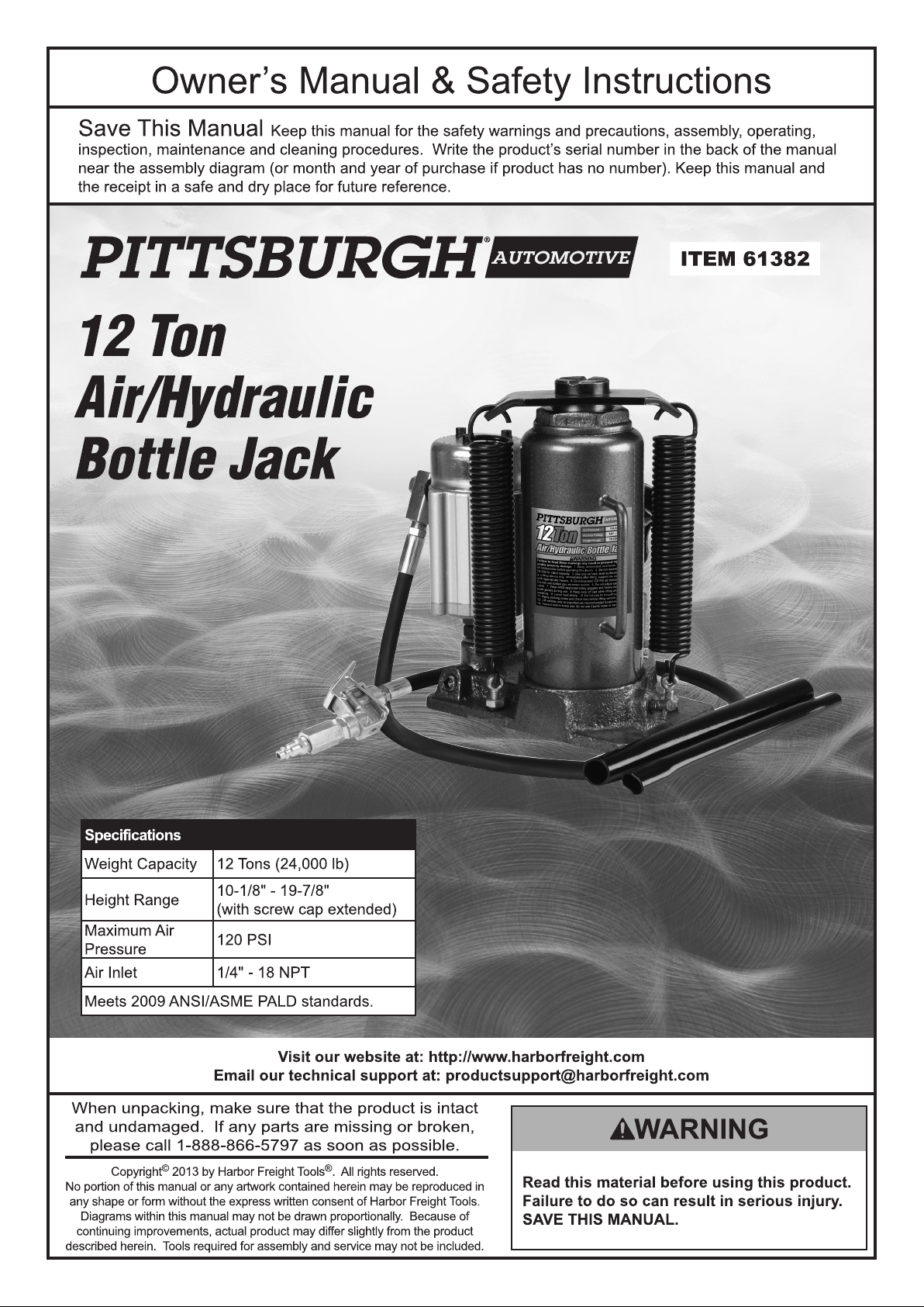
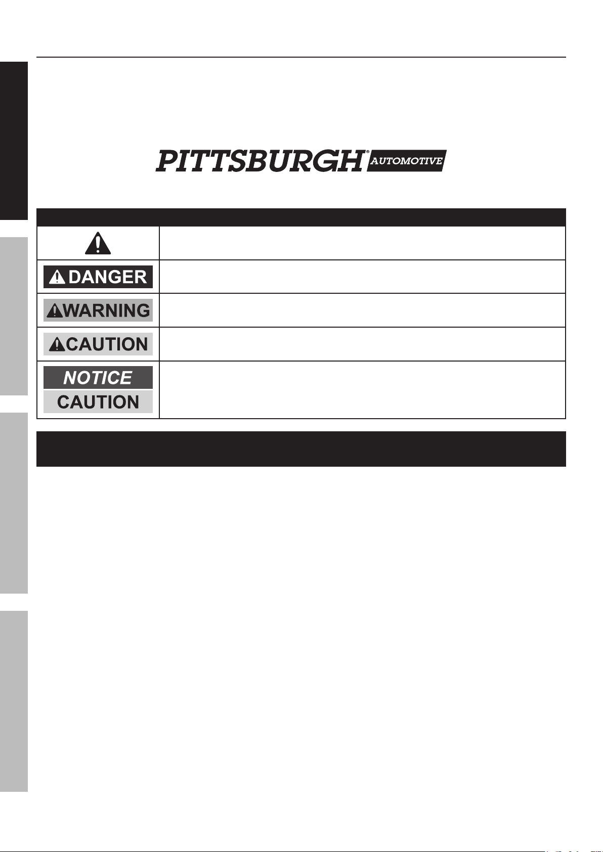
Table of Contents
Safety ......................................................... 2
Setup .......................................................... 4
Operation .................................................... 8
SAFETY OPERATION MAINTENANCESETUP
This is the safety alert symbol. It is used to alert you to potential personal injury hazards.
Maintenance .............................................. 10
Parts List and Diagram .............................. 14
Warranty .................................................... 16
WARNING SYMBOLS AND DEFINITIONS
Obey all safety messages that follow this symbol to avoid possible injury or death.
Indicates a hazardous situation which, if not avoided,
will result in death or serious injury.
Indicates a hazardous situation which, if not avoided,
could result in death or serious injury.
Indicates a hazardous situation which, if not avoided,
could result in minor or moderate injury.
Addresses practices not related to personal injury.
IMPORTANT SAFETY INSTRUCTIONS
1. Study, understand, and follow all instructions
before operating this device.
2. Do not exceed rated capacity.
3. Use only on hard, level surfaces.
4. Lifting device only. Immediately after lifting,
support the vehicle with appropriate means.
5. Do not move or dolly the vehicle while on the jack.
6. Failure to heed these markings may result in
personal injury and/or property damage.
7. Lift only areas of the vehicle as specified
by the vehicle manufacturer.
8. No alterations shall be made to this product.
9. Never work on, under or around a load
supported only by this device.
10. Do not adjust safety valve.
11. Wear ANSI-approved safety goggles and
heavy-duty work gloves during use.
12. Keep clear of load while lifting and lowering.
13. Lower load slowly.
14. Apply parking brake and chock
tires before lifting vehicle.
15. Lift vehicle only at manufacturer
recommended locations.
16. Inspect before every use; do not use
if parts are loose or damaged.
17. Do not use for aircraft purposes.
18. The warnings, precautions, and instructions
discussed in this manual cannot cover all
possible conditions and situations that may occur.
The operator must understand that common sense
and caution are factors, which cannot be built into
this product, but must be supplied by the operator.
19. The brass components of this product contain lead,
a chemical known to the State of California to cause
cancer, birth defects (or other reproductive harm).
(California Health & Safety Code § 25249.5, et seq.)
IMPORTANT! Before first use:
Check hydraulic fluid level and fill to 1/4″ below
the fill port as needed. Thoroughly test the
Jack for proper operation. If it does not work
properly, bleed air from its hydraulic system as
stated in Bleeding Instructions on page 5.
Page 2 For technical questions, please call 1-888-866-5797. Item 61382
Air Source
1. Never connect to an air source that is
capable of exceeding 200 psi.
Over pressurizing the tool may cause
bursting, abnormal operation, breakage
of the tool or serious injury to persons.
Use only clean, dry, regulated compressed air at the
rated pressure or within the rated pressure range as
marked on the tool. Always verify prior to using the
tool that the air source has been adjusted to the rated
air pressure or within the rated air-pressure range.
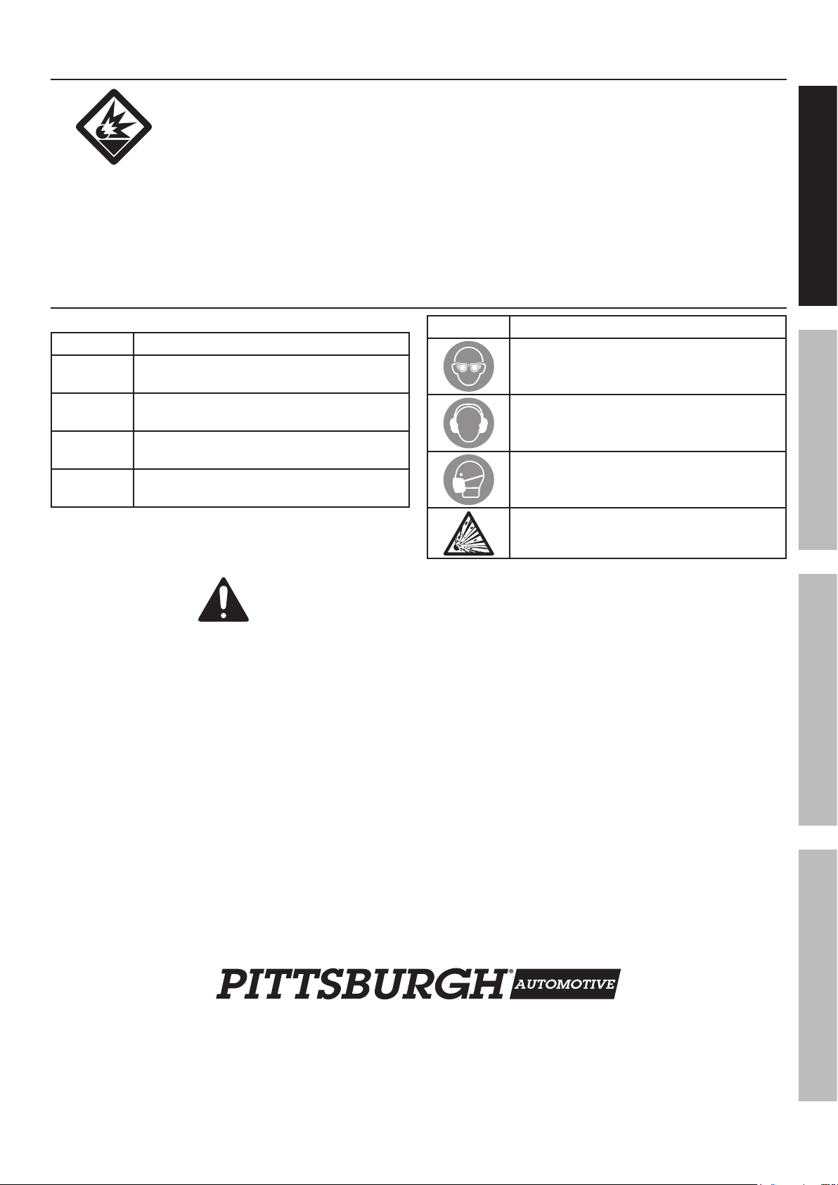
Symbol Definitions
Symbol Property or statement
PSI
CFM
SCFM
NPT
Pounds per square inch of pressure
Cubic Feet per Minute flow
Cubic Feet per Minute flow
at standard conditions
National pipe thread, tapered
2. Never use oxygen, carbon dioxide, combustible
gases or any bottled gas as an air source
for the tool. Such gases are capable of
explosion and serious injury to persons.
SAFETYOPERATIONMAINTENANCE SETUP
Symbol Property or statement
WARNING marking
concerning Risk of Eye Injury.
Wear ANSI-approved eye protection.
WARNING marking concerning Risk of
Hearing Loss. Wear hearing protection.
WARNING marking concerning
Risk of Respiratory Injury. Wear
NIOSH-approved dust mask/respirator.
WARNING marking concerning
Risk of Explosion.
SAVE THESE INSTRUCTIONS.
Page 3For technical questions, please call 1-888-866-5797.Item 61382
Initial Tool Set Up
Read the ENTIRE IMPORTANT SAFETY INSTRUCTIONS section at the beginning of this
manual including all text under subheadings therein before set up or use of this product.
SAFETY OPERATION MAINTENANCESETUP
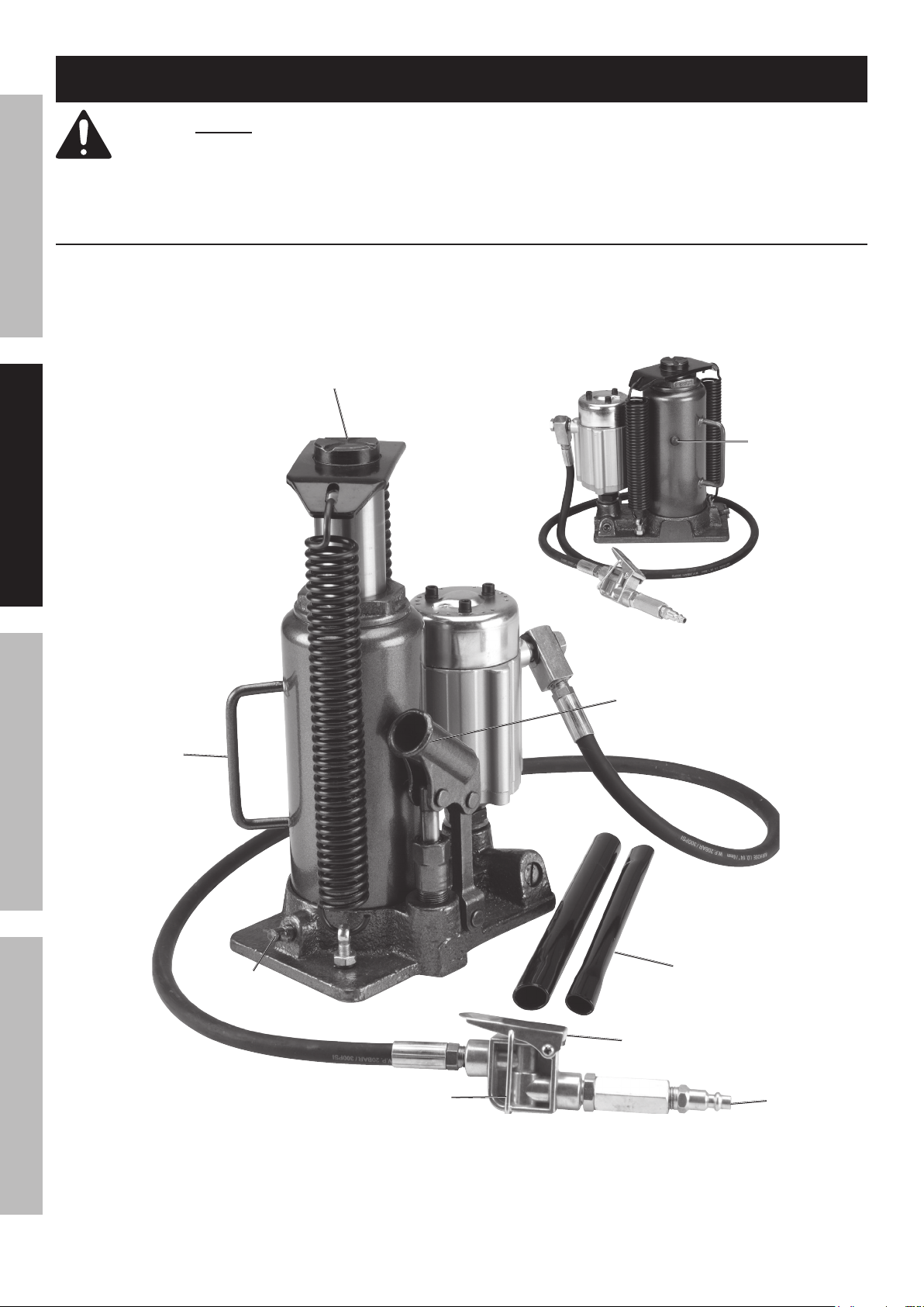
Components and Controls
Saddle
Fill
Plug
Carrying
Handle
Release
Valve
Air Lever
Lock
Figure A
Fulcrum
Handle
Air
Lever
Jack
Air
Inlet
Page 4 For technical questions, please call 1-888-866-5797. Item 61382

Bleeding Instructions
Before each use or if Jack performance decreases,
check for excessive air and proper hydraulic fluid level in Jack. If Jack appears not to be working
properly, it may be necessary to purge its hydraulic system of excessive air as follows:
1. Assemble the Jack Handle by pushing
the two sections together.
2. Remove Fill Plug. Fill with hydraulic fluid
(sold separately) to full level, if necessary.
3. Place the slotted end of the Jack Handle over
the Release Valve, then turn counterclockwise
to open the Release Valve.
4. Insert the Jack Handle into the Fulcrum, apply
downward pressure to the Saddle, then pump
the Jack Handle quickly several times.
Air Supply
TO PREVENT SERIOUS INJURY FROM EXPLOSION:
Use only clean, dry, regulated, compressed air to power this tool. Do not use oxygen,
carbon dioxide, combustible gases, or any other bottled gas as a power source for this tool.
1. Incorporate a filter, regulator with pressure gauge,
oiler, in-line shutoff valve, and quick coupler for best
service, as shown on Figure B: Portable Air Supply
Setup on page 6 and Figure C: Stationary Air
Supply Setup on page 7. An in-line shutoff
ball valve is an important safety device because
it controls the air supply even if the air hose
is ruptured. The shutoff valve should be a
ball valve because it can be closed quickly.
Note: If an automatic oiler system is not used,
add a few drops of Pneumatic Tool Oil to
the airline connection before operation.
Add a few more drops after each hour of continual use.
2. Attach an air hose (not included) to the compressor’s
air outlet.
Connect the air hose to the Jack’s Air Inlet.
Other components, such as a connector
and quick coupler, will make operation
more efficient, but are not mandatory.
WARNING! TO PREVENT SERIOUS INJURY
FROM ACCIDENTAL OPERATION:
Do not install a female quick coupler on the tool.
Such a coupler contains an air valve that will
allow the air tool to retain pressure and operate
accidentally after the air supply is disconnected.
Note: Air flow, and therefore tool performance, can
be hindered by undersized air supply components.
The air hose must be long enough to reach
the work area with enough extra length to
allow free movement while working.
5. Check fluid level and, if necessary,
top off with hydraulic fluid.
6. Close the Release Valve by turning it
clockwise, then replace Fill Plug.
SAFETYOPERATIONMAINTENANCE SETUP
IMPORTANT: After bleeding the Jack, test the
Jack for proper operation prior to its actual use.
7. If, after bleeding, the Jack does not appear
to be working properly, do not use it until
repaired by a qualified service technician.
3. Turn the tool’s throttle or switch to the off position;
refer to Operation section for description of controls.
4. Close the in-line shutoff valve between
the compressor and the tool.
5. Turn on the air compressor according to
the manufacturer’s directions and allow it
to build up pressure until it cycles off.
6. Adjust the air compressor’s output regulator
so that the air output is enough to properly
power the tool, but the output will not exceed
the tool’s maximum air pressure at any time.
Adjust the pressure gradually, while checking the
air output gauge to set the right pressure range.
7. Inspect the air connections for leaks.
Repair any leaks found.
8. If the tool will not be used at this time, turn off
and detach the air supply, safely discharge any
residual air pressure, and release the throttle
and/or turn the switch to its off position
to prevent accidental operation.
Note: Residual air pressure should not be present
after the tool is disconnected from the air supply.
However, it is a good safety measure to attempt to
discharge the tool in a safe fashion after disconnecting
to ensure that the tool is disconnected and unpowered.
Page 5For technical questions, please call 1-888-866-5797.Item 61382
 Loading...