


Table of Contents
Specifications ............................................. 2
Safety ......................................................... 2
Setup .......................................................... 6
SAFETY OPERATION MAINTENANCESETUP
Operation .................................................... 8
Specifications
Maintenance .............................................. 10
Parts List and Diagram .............................. 14
Warranty .................................................... 16
Electrical Rating 120V~ / 60Hz / 12A
Motor No Load Speed 3400 RPM
Log Capacity 20.5" L x 10" Diameter
Hydraulic Fluid Capacity 3.4 Quarts (3.2 Liters)
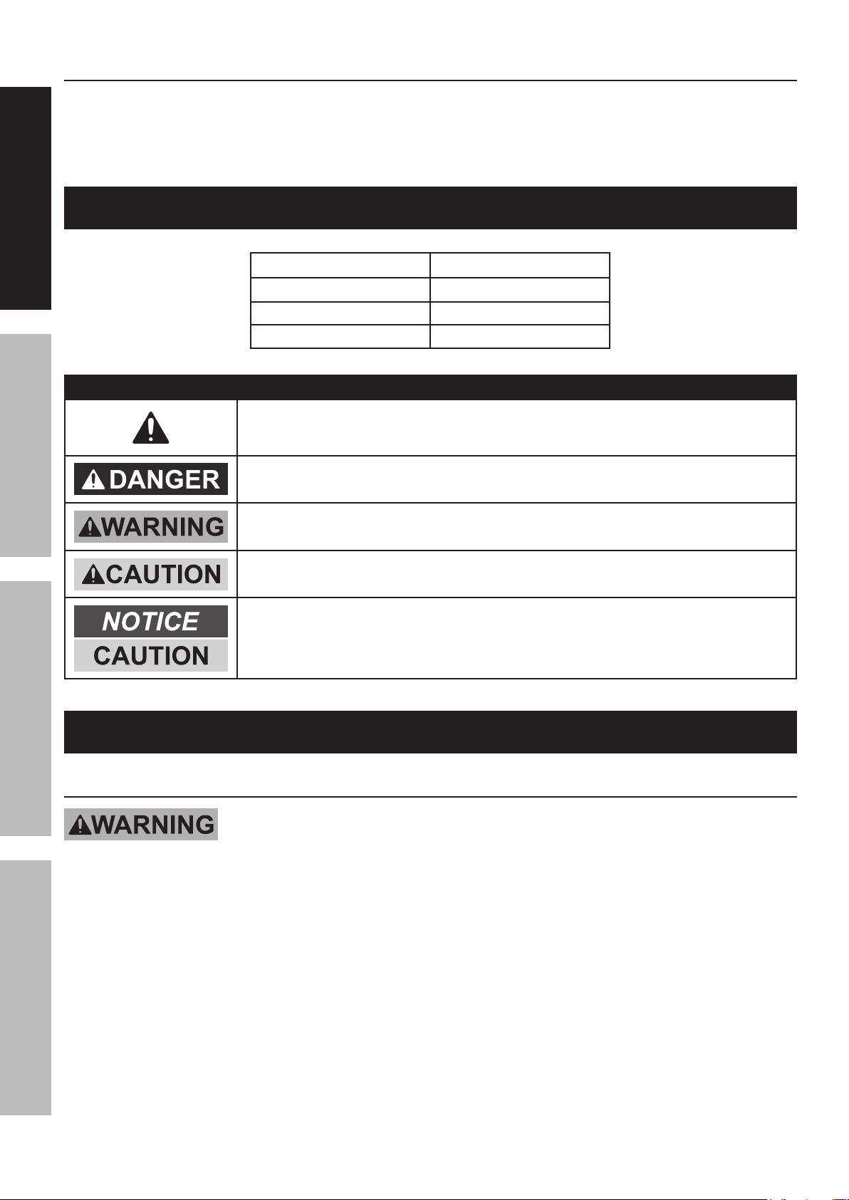
WARNING SYMBOLS AND DEFINITIONS
This is the safety alert symbol. It is used to alert you to potential
personal injury hazards. Obey all safety messages that
follow this symbol to avoid possible injury or death.
Indicates a hazardous situation which, if not avoided,
will result in death or serious injury.
Indicates a hazardous situation which, if not avoided,
could result in death or serious injury.
Indicates a hazardous situation which, if not avoided,
could result in minor or moderate injury.
Addresses practices not related to personal injury.
IMPORTANT SAFETY INFORMATION
General Tool Safety Warnings
Read all safety warnings and instructions.
Failure to follow the warnings and instructions may result in electric shock, fire and/or serious injury.
Save all warnings and instructions for future reference.
1. KEEP GUARDS IN PLACE and in working order.
2. KEEP WORK AREA CLEAN.
Cluttered areas and benches invite accidents.
3. DON’T USE IN DANGEROUS ENVIRONMENT.
Don’t use power tools in damp or wet locations,
or expose them to rain. Keep work area well lighted.
5. MAKE WORKSHOP KID PROOF with padlocks,
master switches, or by removing starter keys.
6. DON’T FORCE TOOL. It will do the job better
and safer at the rate for which it was designed.
7. USE RIGHT TOOL. Don’t force tool or attachment
to do a job for which it was not designed.
4. KEEP CHILDREN AWAY. All visitors should
be kept safe distance from work area.
Page 2 For technical questions, please call 1-800-444-3353. Item 61373

8. WEAR PROPER APPAREL. Do not wear
loose clothing, neckties, rings, bracelets, or
other jewelry which may get caught in moving
parts. Nonslip footwear is recommended.
Wear protective hair covering to contain long hair.
9. ALWAYS USE SAFETY GLASSES. Also use face
or dust mask if cutting operation is dusty. Everyday
eyeglasses only have impact resistant lenses, they
are NOT safety glasses.DON’T OVERREACH.
Keep proper footing and balance at all times.
10. MAINTAIN TOOLS WITH CARE. Keep
tools sharp and clean for best and safest
performance. Follow instructions for
lubricating and changing accessories.
11. DISCONNECT TOOLS before servicing;
when changing accessories, such as
blades, bits, cutters, and the like.
12. REDUCE THE RISK OF UNINTENTIONAL
STARTING. Make sure switch is in
off position before plugging in.
13. USE RECOMMENDED ACCESSORIES.
Consult the owner’s manual for recommended
accessories. The use of improper accessories
may cause risk of injury to persons.
14. NEVER STAND ON TOOL.
Serious injury could occur if the tool is tipped or
if the cutting tool is unintentionally contacted.
15. CHECK DAMAGED PARTS. Before further use
of the tool, a guard or other part that is damaged
should be carefully checked to determine that
it will operate properly and perform its intended
function – check for alignment of moving parts,
binding of moving parts, breakage of parts,
mounting, and any other conditions that may
affect its operation. A guard or other part that is
damaged should be properly repaired or replaced.
16. NEVER LEAVE TOOL RUNNING
UNATTENDED. TURN POWER OFF.
SAFETYOPERATIONMAINTENANCE SETUP
Log Splitter Safety Warnings
For Your Own Safety Read Instruction
Manual Before Operating Log Splitter.
1. DO NOT OPERATE WITH ANY GUARD
DISABLED, DAMAGED, OR REMOVED. Keep
guards in place and in good working order.
2. Wear ANSI-approved safety goggles under
full face shield, heavy-duty work gloves
and steel-toe work boots during use.
3. Crushing hazard. Never place hands or feet
between the log and splitter wedge, or between the
log and the ram during the forward or reverse stroke.
4. Never place hands or body near a hydraulic
fluid leak or check for a leak with hands or other
body parts. High-pressure fluid can be forced
under the skin resulting in serious injury.
5. Never split a log that contains any foreign
materials (nails, for example).
6. Do not use Splitter on logs longer than 20.5"
or with a diameter greater than 10".
7. Hold the rounded, bark side of logs when
loading or positioning, never the ends. Never
place hands or any body parts between a
log and any part of the Log Splitter.
8. Never load or unload logs while
the Ram is moving.
9. Do not attempt to split logs across the
grain. Doing so will damage the Log Splitter
and could cause pieces of log to be thrown,
injuring the operator or bystanders.
10. Never attempt to split more than one log at a time.
A piece of log can unexpectedly be thrown from
the machine, causing severe personal injury.
11. Remove split logs away from the Log
Splitter immediately. Split logs left near
the Log Splitter are a tripping hazard.
12. The use of accessories or attachments not
recommended by the manufacturer may
result in a risk of injury to persons.
13. Set up and operate only on a flat, level,
dry and solid surface with wheels chocked.
14. When servicing use only identical replacement parts.
15. Only use safety equipment that has been approved
by an appropriate standards agency. Unapproved
safety equipment may not provide adequate
protection. Eye protection must be ANSI-approved
and breathing protection must be NIOSH-approved
for the specific hazards in the work area.
16. Stay alert, watch what you are doing and use
common sense when operating a power tool.
Do not use a power tool while you are tired or
under the influence of drugs, alcohol or medication.
A moment of inattention while operating power tools
may result in serious personal injury. Industrial
applications must follow OSHA guidelines.
Page 3For technical questions, please call 1-800-444-3353.Item 61373

Log Splitter Safety Warnings (continued)
17. Maintain labels and nameplates on the tool.
These carry important safety information.
If unreadable or missing, contact
SAFETY OPERATION MAINTENANCESETUP
Harbor Freight Tools for a replacement.
18. Avoid unintentional starting.
Prepare to begin work before turning on the tool.
19. This product is not a toy. Keep it
out of reach of children.
20. People with pacemakers should consult their
physician(s) before use. Electromagnetic fields in
close proximity to heart pacemaker could cause
pacemaker interference or pacemaker failure.
21. WARNING: Some dust created by power
sanding, sawing, grinding, drilling, and other
construction activities, contains chemicals
known [to the State of California] to cause
cancer, birth defects or other reproductive harm.
Some examples of these chemicals are:
• Lead from lead-based paints
• Crystalline silica from bricks and cement or other
masonry products
• Arsenic and chromium from
chemically treated lumber
Your risk from these exposures varies,
depending on how often you do this type of work.
To reduce your exposure to these chemicals:
work in a well ventilated area, and
work with approved safety equipment, such
as those dust masks that are specially
designed to filter out microscopic particles.
(California Health & Safety Code § 25249.5, et seq.)
22. WARNING: Handling the cord on this product will
expose you to lead, a chemical known to the State of
California to cause cancer, and birth defects or other
reproductive harm. Wash hands after handling.
(California Health & Safety Code § 25249.5, et seq.)
23. The warnings, precautions, and instructions
discussed in this instruction manual cannot cover all
possible conditions and situations that may occur.
It must be understood by the operator that
common sense and caution are factors
which cannot be built into this product,
but must be supplied by the operator.
SAVE THESE INSTRUCTIONS.
Grounding Instructions
TO PREVENT ELECTRIC SHOCK AND DEATH FROM INCORRECT
GROUNDING WIRE CONNECTION READ AND FOLLOW THESE INSTRUCTIONS:
110-120 V~ Grounded Tools: Tools with Three Prong Plugs
1. In the event of a malfunction or breakdown,
grounding provides a path of least resistance for
electric current to reduce the risk of electric shock.
This tool is equipped with an electric cord having an
equipment-grounding conductor and a grounding
plug. The plug must be plugged into a matching
outlet that is properly installed and grounded in
accordance with all local codes and ordinances.
3. Improper connection of the equipment-grounding
conductor can result in a risk of electric shock.
The conductor with insulation having an outer
surface that is green with or without yellow
stripes is the equipment-grounding conductor.
If repair or replacement of the electric cord or
plug is necessary, do not connect the equipmentgrounding conductor to a live terminal.
2. Do not modify the plug provided – if it will
not fit the outlet, have the proper outlet
installed by a qualified electrician.
Page 4 For technical questions, please call 1-800-444-3353. Item 61373
4. Check with a qualified electrician or service
personnel if the grounding instructions are not
completely understood, or if in doubt as to whether
the tool is properly grounded.Use only 3-wire
extension cords that have 3-prong grounding plugs
and 3-pole receptacles that accept the tool’s plug.
5. Repair or replace damaged or
worn cord immediately.
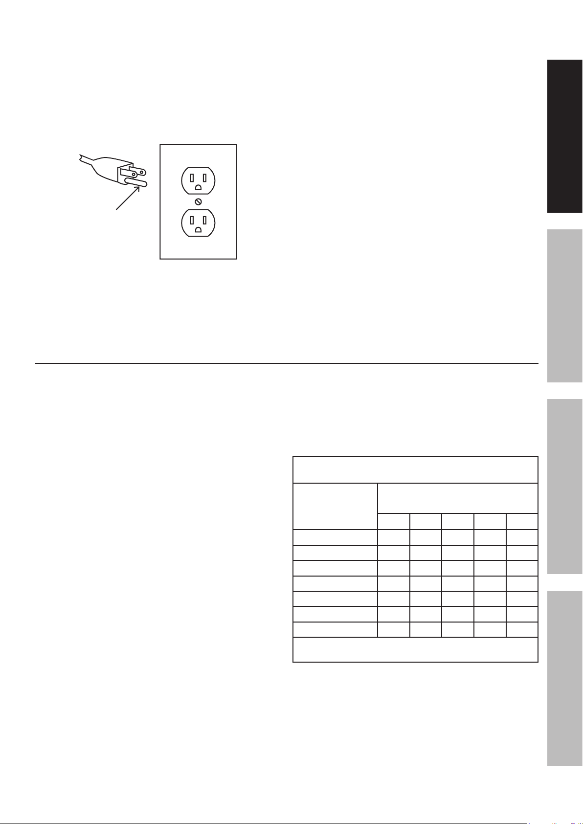
Grounding
Pin
125 V~ 3-Prong Plug and Outlet
(for up to 125 V~ and up to 15 A)
6. This tool is intended for use on a circuit that has
an outlet that looks like the one illustrated above
in 125 V~ 3-Prong Plug and Outlet. The tool has
a grounding plug that looks like the plug illustrated
above in 125 V~ 3-Prong Plug and Outlet.
7. The outlet must be properly installed and grounded
in accordance with all codes and ordinances.
8. Do not use an adapter to connect
this tool to a different outlet.
SAFETYOPERATIONMAINTENANCE SETUP
Extension Cords
1. Grounded tools require a three wire extension cord.
Double Insulated tools can use either
a two or three wire extension cord.
2. As the distance from the supply outlet increases,
you must use a heavier gauge extension cord.
Using extension cords with inadequately sized wire
causes a serious drop in voltage, resulting in loss of
power and possible tool damage. (See Table A.)
3. The smaller the gauge number of the wire, the
greater the capacity of the cord. For example,
a 14 gauge cord can carry a higher current
than a 16 gauge cord. (See Table A.)
4. When using more than one extension cord
to make up the total length, make sure
each cord contains at least the minimum
wire size required. (See Table A.)
5. If you are using one extension cord for more
than one tool, add the nameplate amperes
and use the sum to determine the required
minimum cord size. (See Table A.)
6. If you are using an extension cord outdoors, make
sure it is marked with the suffix “W-A” (“W” in
Canada) to indicate it is acceptable for outdoor use.
7. Make sure the extension cord is properly wired
and in good electrical condition. Always replace
a damaged extension cord or have it repaired
by a qualified electrician before using it.
8. Protect the extension cords from sharp objects,
excessive heat, and damp or wet areas.
TABLE A: RECOMMENDED MINIMUM WIRE
GAUGE FOR EXTENSION CORDS* (120/240 VOLT)
NAMEPLATE
AMPERES
(at full load)
0 – 2.0 18 18 18 18 16
2.1 – 3.4 18 18 18 16 14
3.5 – 5.0 18 18 16 14 12
5.1 – 7.0 18 16 14 12 12
7.1 – 12.0 18 14 12 10 -
12.1 – 16.0 14 12 10 - -
16.1 – 20.0 12 10 - - -
* Based on limiting the line voltage drop to five volts at
150% of the rated amperes.
EXTENSION CORD
LENGTH
25´ 50´ 75´ 100´ 150´
Page 5For technical questions, please call 1-800-444-3353.Item 61373

Symbology
SAFETY OPERATION MAINTENANCESETUP
V
~
A
n0 xxxx/min.
Double Insulated
Canadian Standards Association
Underwriters Laboratories, Inc.
Volts
Alternating Current
Amperes
No Load Revolutions per Minute (RPM)
Read the manual before
set-up and/or use.
WARNING marking concerning Risk
of Eye Injury. Wear ANSI-approved
safety goggles with side shields.
WARNING marking concerning Risk
of Facial Injury from flying debris.
Wear ANSI-approved full face shield.
WARNING marking concerning
Risk of Foot Injury. Wear
steel-toe work boots.
WARNING marking concerning
Risk of Hand Injury. Wear
heavy-duty work gloves.
WARNING marking concerning
Risk of Electric Shock.
Properly connect power cord
to appropriate outlet.
WARNING marking concerning
Crushing Hazard. Keep hands and
feet away from moving parts.
SAVE THESE INSTRUCTIONS.
Setup - Before Use:
Read the ENTIRE IMPORTANT SAFETY INFORMATION section at the beginning of this
manual including all text under subheadings therein before set up or use of this product.
TO PREVENT SERIOUS INJURY FROM ACCIDENTAL OPERATION:
Turn the Power Switch of the tool off and unplug the tool from its electrical outlet
before performing any procedure in this section.
Note: For additional information regarding the parts listed in the following pages,
refer to the Assembly Diagram near the end of this manual.
Assembly
Control Handle (37)
1. Insert the Control Handle (37) through the
slot in the Shield (32) and into the shaft
on the Control Handle Bracket (36).
Shield (32)
2. Turn the Control Handle to tighten in place.
Page 6 For technical questions, please call 1-800-444-3353. Item 61373
Control Handle
Bracket (36)
Figure A: Control Handle Assembly

Functions
Control
Handle
Ram Cutting Wedge
SAFETYOPERATIONMAINTENANCE SETUP
Lift
Handle
Power
Switch
Power
Cable
Rubber
Feet
Guide Plate
Vent Plug
Drain Bolt /
Dipstick
Front Leg
Page 7For technical questions, please call 1-800-444-3353.Item 61373

Operating Instructions
Read the ENTIRE IMPORTANT SAFETY INFORMATION section at the beginning of this
manual including all text under subheadings therein before set up or use of this product.
SAFETY OPERATION MAINTENANCESETUP
Tool Set Up
TO PREVENT SERIOUS INJURY FROM ACCIDENTAL OPERATION:
Turn the Power Switch of the tool off and unplug the tool from its electrical outlet
before performing any procedure in this section.
TO PREVENT SERIOUS INJURY:
DO NOT OPERATE WITH ANY GUARD DISABLED, DAMAGED,
OR REMOVED. Keep guards in place and in good working order.
Checking Hydraulic Fluid Level
IMPORTANT! Before first use and before each use
thereafter, check the hydraulic fluid level of the Log
Splitter when fluid is cold. Operating without sufficient
fluid in the reservoir can badly damage the pump.
1. Unplug the Power Cable.
2. Use the Lift Handle located on the Front Leg to
raise the Log Splitter to a standing position on the
wheel end of the unit. Be careful not to damage
the Control Handle when standing the tool upright.
3. Remove the Drain Bolt / Dipstick from the fluid
reservoir with a hex key.
4. Wipe off the Drain Bolt / Dipstick and thread
it back into the fluid reservoir. Remove and
check to make sure the fluid level is within
the acceptable range between the two marks
on the Dipstick. Refer to Figure B.
Fluid Level Range
Drain
Bolt /
Dipstick
Lift Handle
Vent
Plug
Control Handle
Fluid
Figure B: Dipstick
5. If the fluid level is low, add sufficient AW32
hydraulic fluid (not included) to bring the
level up to the acceptable range.
6. If the fluid level is within the acceptable range,
wipe the Drain Bolt / Dipstick clean and replace
it in the fluid reservoir and tighten securely.
Page 8 For technical questions, please call 1-800-444-3353. Item 61373
7. Use the Lift Handle to return the unit to its
8. Open the Vent Plug by turning it
9. Start the motor and use the Control Handle to
Figure C: Checking / Adding Fluid
normal, horizontal operating position.
counterclockwise 4 – 5 turns.
cycle the Ram forward and back several times
to remove excess air from the fluid reservoir.

Workpiece and Work Area Set Up
1. Designate a work area that is clean and well-lit.
The work area must not allow access by children
or pets to prevent distraction and injury.
2. Route the power cord along a safe route to reach
the work area without creating a tripping hazard or
exposing the power cord to possible damage. The
power cord must reach the work area with enough
extra length to allow free movement while working.
3. There must not be objects, such as utility lines,
nearby that will present a hazard while working.
General Operating Instructions
1. Check the hydraulic fluid level; fill as necessary.
2. Place wheel chocks (not included) on each side of
the wheels to keep the Log Splitter from moving.
3. Make sure that the Power Switch is in the
off-position, then plug in the Log Splitter.
4. Maximum log size for this Log Splitter is
20.5" long and 10" in diameter. Attempting to
cut logs that exceed those measurements is
dangerous and may damage the Log Splitter.
5. Use a chainsaw (not included) to cut logs
square on each end before splitting. Log ends
that are not cut square can slide out while
splitting and cause a safety hazard or cause
excessive force to Log Splitter components.
6. Never split a log that contains any foreign materials
(nails, for example). Do not use odd-shaped,
uneven logs or logs that are knotted or curved.
7. Push the Control Handle down to move
the Ram forward into the log, driving it onto
the Cutting Wedge, splitting the log.
8. Release the Control Handle to retract
the Ram automatically, remove split log
pieces, and begin loading the next log.
SAFETYOPERATIONMAINTENANCE SETUP
4. Press the Power Switch to turn on the tool.
5. Open the Vent Plug by turning it
counterclockwise 4 – 5 turns.
Note: Operating the Log Splitter without the
Vent Plug open will cause pressure to build
up in the hydraulic reservoir which could
damage seals and affect normal operation.
6. Position log lengthwise in the direction of the
grain on the Machine Body of the Splitter
between the Guide Plates. Place one end
of log against the Cutting Wedge. The log
must be stable so that it will split properly.
Removing a Stuck Log
A log that is too stringy or tough to split completely
can become stuck on the Cutting Wedge if the
Wedge becomes embedded in the log and the
log doesn’t completely split and separate. If
this happens, follow the directions below.
1. Fully retract the Ram.
2. Turn off the Power Switch and
unplug the Power Cable.
3. Remove the stuck log from the Cutting
Wedge manually with a pry bar.
Note: If difficulty is experienced splitting harder wood,
do not keep pressure on the log by trying to force
the Log Splitter. Release the Control Handle after
five seconds to retract the ram and avoid damage
to the tool. If the motor stops, turn off the motor and
then turn it back on again to continue operation.
9. To retract the Ram at any time,
release the Control Handle.
10. Close the Vent Plug whenever
moving the Log Splitter.
11. To prevent accidents, turn off the Log Splitter,
unplug from its electrical outlet, and close
the Vent Plug after use. Clean, then store
the tool indoors out of children’s reach.
WARNING! Be extremely careful when removing
the log as pieces may fly off as they separate from
the Wedge. Never attempt to remove a stuck log
by using the hydraulic force of the Log Splitter,
modifying the Log Splitter, or adding attachments
to the Log Splitter. Personal injury could result
from log or metal pieces flying out at high speed,
or the Log Splitter could become damaged.
4. Do not attempt to re-split a stuck log once it
has been removed from the Wedge. Manually
split with a maul, or cut with a chainsaw.
Page 9For technical questions, please call 1-800-444-3353.Item 61373

Maintenance and Servicing
Procedures not specifically explained in this manual must
be performed only by a qualified technician.
SAFETY OPERATION MAINTENANCESETUP
TO PREVENT SERIOUS INJURY FROM ACCIDENTAL OPERATION:
Turn the Power Switch of the tool off and unplug the tool from its electrical outlet
before performing any procedure in this section.
TO PREVENT SERIOUS INJURY FROM TOOL FAILURE:
Do not use damaged equipment. If abnormal noise or vibration
occurs, have the problem corrected before further use.
Cleaning, Maintenance, and Lubrication
1. BEFORE EACH USE, inspect the general
condition of the Log Splitter. Check for:
• loose hardware
• misalignment or binding of moving parts
• cracked or broken parts
• damaged electrical wiring
• leaking hydraulic fluid
(Do not check for leaks during operation.)
• any other condition that may
affect its safe operation.
2. AFTER USE, wipe external surfaces of
the tool with clean cloth to remove any
tree sap, dirt or hydraulic fluid.
3. Periodically as needed, use a fine-toothed file
to smooth out any burrs, nicks or crushed areas
and sharpen the cutting edge of the Wedge.
4. WARNING! If the supply cord of this
power tool is damaged, it must be replaced
only by a qualified service technician.
Page 10 For technical questions, please call 1-800-444-3353. Item 61373

Hydraulic Fluid Maintenance / Bleeding
Change the hydraulic fluid in the Log
Splitter after every 100 hours of use.
Replacing Hydraulic Fluid
1. Remove the Rubber Feet from
the ends of the Front Leg.
2. Place the Front Leg of the tool in a five quart
or greater capacity container. Raise the
wheeled end of the Log Splitter using blocks
and wheel chocks (not included), tilting the unit
to an angle of approximately 30 degrees.
Vent Plug
Drain Bolt /
Dipstick
Front Leg
Figure D: Draining the Fluid Reservoir
3. Remove the Drain Bolt / Dipstick with a hex
key, disconnect the Vent Plug and drain the
fluid reservoir. Dispose of the old hydraulic
fluid in accordance with local regulations.
4. After the fluid has drained from the fluid
reservoir, use the Lift Handle located on the
Front Leg to raise the Log Splitter to a standing
position on the wheel end of the unit. Be
careful not to damage the Control Handle when
standing the tool upright. Refer to Figure C:
Checking / Adding Fluid on page 8.
5. Refill the fluid reservoir with 3.4 quarts (3.2 liters)
of fresh AW32 hydraulic fluid (not included).
Note: If AW32 hydraulic fluid is not available,
Dextron II automatic transmission fluid may be
used as a substitute. DO NOT mix Dextron II
with AW32 hydraulic fluid—drain reservoir
completely if substituting Dextron II.
6. Wipe off the Drain Bolt / Dipstick and thread it
into the fluid reservoir. Remove and check to
make sure the fluid level is within the acceptable
range between the two marks on the Dipstick.
Refer to Figure B: Dipstick on page 8.
7. Replace the Vent Plug and Drain
Bolt / Dipstick. Tighten securely.
8. Replace the Rubber Feet on the
ends of the Front Leg.
9. Use the Lift Handle to return the unit to its
normal, horizontal operating position.
SAFETYOPERATIONMAINTENANCE SETUP
Bleeding the Hydraulic System
Trapped air may accumulate in the fluid reservoir
causing the Ram to move erratically or not at all,
making it necessary to bleed the hydraulic system
of excess air. To bleed the hydraulic system:
1. Unplug the Power Cable.
2. Use the Lift Handle located on the Front Leg
to raise the Log Splitter to a standing position
on the wheel end of the unit. Be careful
not to damage the Control Handle when
standing the tool upright. Refer to Figure C:
Checking / Adding Fluid on page 8.
3. Remove the Drain Bolt / Dipstick
with a hex key.
10. Open the Vent Plug by turning it
counterclockwise 4 – 5 turns.
11. Plug in the tool, start the motor and use the Control
Handle to cycle the Ram forward and back several
times to remove excess air from the fluid reservoir.
4. Wipe off the Drain Bolt / Dipstick and thread
it back into the fluid reservoir. Remove and
check the fluid level; add fluid as needed
to bring within the acceptable range. Refer
to Figure B: Dipstick on page 8.
5. Replace the Drain Bolt / Dipstick and
tighten securely.
6. Use the Lift Handle to return the unit to its
normal, horizontal operating position.
7. Open the Vent Plug by turning it
counterclockwise 4 – 5 turns.
8. Plug in the tool, start the motor and use the Control
Handle to cycle the Ram forward and back several
times to remove excess air from the fluid reservoir.
Page 11For technical questions, please call 1-800-444-3353.Item 61373

Troubleshooting
Problem Possible Causes Likely Solutions
Tool will not start. 1. Power Cable not connected.
SAFETY OPERATION MAINTENANCESETUP
Wood will not
split, or splits
extremely slowly.
Ram vibrates,
moves erratically,
or does not
move.
Fluid leaking
from hydraulic
system.
2. No power at outlet.
3. Tool’s overload protection device has
tripped to protect tool from damage.
4. Internal damage or wear. (Carbon
brushes or switch, for example.)
1. Log not positioned properly.
2. The size or hardness of the log
exceeds the machine’s capacity.
3. Cutting Wedge is dull.
4. Hydraulic fluid level is low.
5. Low maximum pressure rating
adjustment was made on the
Maximum Pressure Limiting Screw.
1. Log Splitter not on level ground.
2. Hydraulic fluid level is low.
3. Excessive air trapped in
the hydraulic system.
1. Accumulated air is trapped in
hydraulic system while operating.
2. Tool moved with Vent Plug loosened.
3. Drain Bolt not tightened securely.
4. Hydraulic fittings and/or
seals are worn.
1. Check that Power Cable is plugged in.
2. Check power at outlet. If outlet is unpowered,
turn off tool and check circuit breaker.
If breaker is tripped, make sure circuit is right
capacity for tool and circuit has no other loads.
3. Turn off and unplug tool and allow to cool for
1/2 hour, then restart. If problem is not solved,
have qualified technician service tool.
4. Have qualified technician service tool.
1. Reposition log. Refer to General
Operating Instructions on page 9.
2. Only split logs within the Log Capacity range shown
in Specifications on page 2. Capacity will be
limited on hardwood logs and green lumber.
3. Sharpen the Cutting Wedge. Refer to
Maintenance and Servicing on page 10.
4. Check fluid level and add fluid as needed.
5. Have qualified technician adjust
maximum pressure rating.
1. Reposition tool so it is level with
both ends at same height.
2. Check fluid level and add fluid as needed.
3. Bleed hydraulic system. Refer to Bleeding
the Hydraulic System on page 11. Be sure
Vent Plug is loose when operating tool.
1. Loosen Vent Plug before operating tool.
2. Tighten Vent Plug before moving tool.
3. Tighten the Drain Bolt.
4. Have qualified technician service tool.
Follow all safety precautions whenever diagnosing or servicing the tool.
Disconnect power supply before service.
Page 12 For technical questions, please call 1-800-444-3353. Item 61373

PLEASE READ THE FOLLOWING CAREFULLY
THE MANUFACTURER AND/OR DISTRIBUTOR HAS PROVIDED THE PARTS LIST AND ASSEMBLY DIAGRAM
IN THIS MANUAL AS A REFERENCE TOOL ONLY. NEITHER THE MANUFACTURER OR DISTRIBUTOR
MAKES ANY REPRESENTATION OR WARRANTY OF ANY KIND TO THE BUYER THAT HE OR SHE IS
QUALIFIED TO MAKE ANY REPAIRS TO THE PRODUCT, OR THAT HE OR SHE IS QUALIFIED TO REPLACE
ANY PARTS OF THE PRODUCT. IN FACT, THE MANUFACTURER AND/OR DISTRIBUTOR EXPRESSLY
STATES THAT ALL REPAIRS AND PARTS REPLACEMENTS SHOULD BE UNDERTAKEN BY CERTIFIED AND
LICENSED TECHNICIANS, AND NOT BY THE BUYER. THE BUYER ASSUMES ALL RISK AND LIABILITY
ARISING OUT OF HIS OR HER REPAIRS TO THE ORIGINAL PRODUCT OR REPLACEMENT PARTS
THERETO, OR ARISING OUT OF HIS OR HER INSTALLATION OF REPLACEMENT PARTS THERETO.
SAFETYOPERATIONMAINTENANCE SETUP
Record Product’s Serial Number Here:
Note: If product has no serial number, record month and year of purchase instead.
Note: Some parts are listed and shown for illustration purposes only,
and are not available individually as replacement parts.
Page 13For technical questions, please call 1-800-444-3353.Item 61373

Parts List and Diagram
Parts List
SAFETY OPERATION MAINTENANCESETUP
Part Description Qty
1 Machine Body / Cutting Wedge 1
2 Ram Cap and Shaft 1
3 Upper Nylon Cushion 1
4 Lower Nylon Cushion 1
5 Ram Base Plate 1
6 Flat Washer M8 X 1 6
7 Spring Washer M8 X 2.3 6
8 Inner Hex Bolt M8 X 15 6
9 Double-Screw Bolt M10 X 813 4
10 Cylinder Tube Ø55 X 743 1
11 Seal Ø55 x 3.1 1
12 Seal Cover 1
13 Piston Head 1
14 O-Ring Ø50 x 3.5 1
15 Piston Shaft 1
16 Retracting Spring 1
17 Nut M14 4
18 Lock Nut M14 2
19 Paper Seal Ring 2
20 O-Ring Ø30 x 2.65 1
21 Dust Seal 1
22 Reservoir Cover 1
23 O-Ring Ø6 x 1 1
24 Vent Plug M4 x 10 1
25 Copper Seal Washer M14 x 1 1
26 Drain Bolt / Dipstick 1
27 Hydraulic Valve 1
28 O-Ring Ø14 x 2.4 4
29 Flat Washer M10 x 1 4
30 Spring Washer M10 x 2 4
31 Nut M10 4
32 Shield 1
33 Flat Washer M10 x 2 4
34 Snap Head Nut M10 4
35 Torsion Spring 1
36 Control Handle Bracket 1
37 Control Handle Lever Ø12.5 X 134 1
38 Fluid Tube Ø14 / Ø10 x 100 x 1 1
39 O-Ring Ø18 x 1.9 2
40 Copper Seal Washer M14 x 1 2
41 Fluid Tube Screw M14 x 30 2
42 Inner Hex Bolt M8 x 20 4
43 Spring Washer M8 x 2.3 4
Part Description Qty
44 Hydraulic Pump 1
45 O-Ring Ø18 x 1.9 1
46 Fluid Suction Tube Ø14 / Ø10 x 100 x 1 1
47 Copper Seal Washer M14 X 1 3
48 Fluid Tube Screw M14 X 30 2
49 Fluid Filter 1
50 Inner Hex Bolt M8 x 35 4
51 Spring Washer M8 x 2.3 4
52 Flat Washer M8 x 1 4
53 Electric Motor 1
54 Fan 1
55 Shaft Circlip Ø16 1
56 Fan Cover Ø162 1
57 Flat Washer M4 x 1 3
58 Phillips Head Screw M4 x 10 3
59 Outlet Box 1
60 Rubber Gasket 1
61 Outlet Box Cover 1
62 Phillips Head Screw M4 x 10 6
63 Power Switch 1
64 Capacitor 60uf 1
65 Cable Fastener Nut 1
66 Cable Fastener 1
67 Cable Fastener Bolt 1
68 Power Cable Sleeve 1
69 Power Cable 1
70 Front Leg 1
71 Phillips Head Screw M6 x 15 4
72 Flat Washer M6 x 1 8
73 Spring Washer M6 x 2 4
74 Nut M6 4
75 Rubber Foot 2
76 Lift Handle 1
77 Phillips Head Screw M6 x 15 2
78 Guide Plate 2
79 Flat Washer M8 X 1 4
80 Spring Washer M8 X 2 4
81 Inner Hex Bolt M8 X 12 4
82 Wheel Frame 1
83 Flat Washer M17 x 2 2
84 Rubber Wheel 2
85 Flat Washer M10 x 1 2
86 Lock Nut M10 2
Page 14 For technical questions, please call 1-800-444-3353. Item 61373

Assembly Diagram
2423
25 26
19
20 21 22
9
15
78
81
80
79
28
10
13
14
12
11
18
17
SAFETYOPERATIONMAINTENANCE SETUP
77
76
70
16
72
73
74
57
58
55
75
71
56
54
1
2
48
45
30
31
32
37
33
3
46
47
29
49
27
35
36
39
40
41
4
5
82
83
38
6
7
53
8
59
50
51
52
44
6364
42 43
6061
62
84
85
86
6968
67
66
65
34
Page 15For technical questions, please call 1-800-444-3353.Item 61373

Limited 90 Day Warranty
Harbor Freight Tools Co. makes every effort to assure that its products meet high quality and durability standards,
and warrants to the original purchaser that this product is free from defects in materials and workmanship for the
period of 90 days from the date of purchase. This warranty does not apply to damage due directly or indirectly,
to misuse, abuse, negligence or accidents, repairs or alterations outside our facilities, criminal activity, improper
installation, normal wear and tear, or to lack of maintenance. We shall in no event be liable for death, injuries
to persons or property, or for incidental, contingent, special or consequential damages arising from the use of
our product. Some states do not allow the exclusion or limitation of incidental or consequential damages, so the
above limitation of exclusion may not apply to you. THIS WARRANTY IS EXPRESSLY IN LIEU OF ALL OTHER
WARRANTIES, EXPRESS OR IMPLIED, INCLUDING THE WARRANTIES OF MERCHANTABILITY AND FITNESS.
To take advantage of this warranty, the product or part must be returned to us with transportation charges
prepaid. Proof of purchase date and an explanation of the complaint must accompany the merchandise.
If our inspection verifies the defect, we will either repair or replace the product at our election or we may
elect to refund the purchase price if we cannot readily and quickly provide you with a replacement. We will
return repaired products at our expense, but if we determine there is no defect, or that the defect resulted
from causes not within the scope of our warranty, then you must bear the cost of returning the product.
This warranty gives you specific legal rights and you may also have other rights which vary from state to state.
3491 Mission Oaks Blvd. • PO Box 6009 • Camarillo, CA 93011 • (800) 444-3353
 Loading...