

Harbor Freight Tools 61369 Product manual
Specifications
Table Top Dimensions 30" x 19-7/8"
Table Height 32-7/8"
Maximum Weight Capacity 350 lb
IMPORTANT SAFETY INFORMATION
Assembly Precautions
1. Assemble only according to these instructions.
Improper assembly can create hazards.
2. Wear ANSI-approved safety goggles and
heavy-duty work gloves during assembly.
3. Keep assembly area clean and well lit.
Use Precautions
1. This product is not a toy. Do not allow
children to play with or near this item.
2. Use as intended only. Do not sit or stand on Table.
3. Inspect before every use; do not use
if parts are loose or damaged.
4. Use only on flat, level, hard surface.
Assembly Instructions
Read the ENTIRE IMPORTANT SAFETY INFORMATION section at the beginning of this document
including all text under subheadings therein before set up or use of this product.
4. Keep bystanders out of the area during assembly.
5. Do not assemble when tired or when under the
influence of alcohol, drugs or medication.
6. Weight capacity and other product capabilities apply
to properly and completely assembled product only.
5. Do not exceed listed weight capacity. Tighten
all knobs securely before applying load.
Be aware of dynamic loading!
Sudden load movement may briefly create
excess load causing product failure.
6. Maintain product labels and nameplates.
These carry important safety information.
If unreadable or missing, contact
Harbor Freight Tools for a replacement.
Note: For additional information regarding the parts listed in the following pages,
refer to the Assembly Diagram near the end of this manual.
Unwrap and separate all parts on a clear work area.
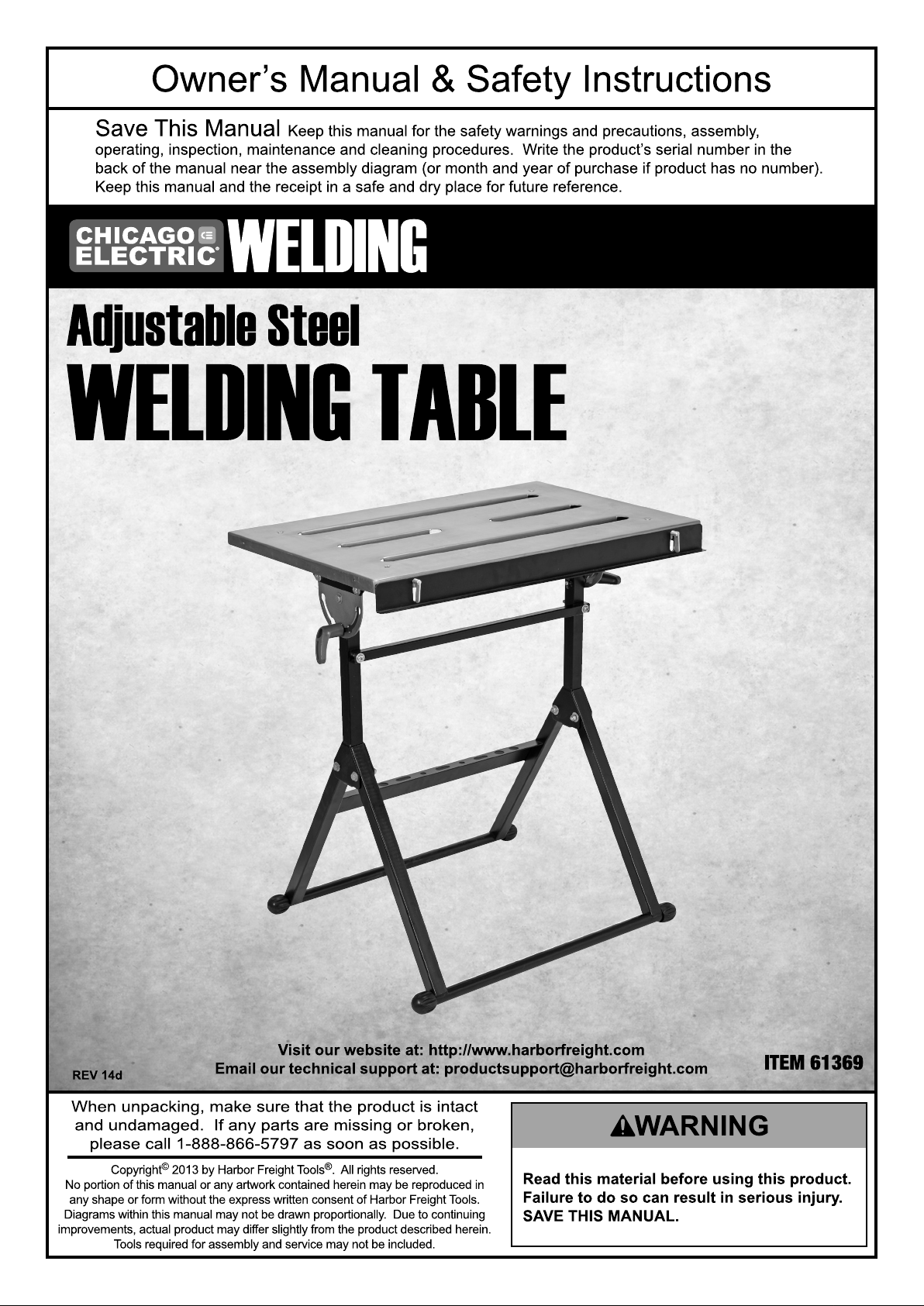
Vertical Post – Angle Bracket Assembly
Attach the two Angle Brackets (6) to the Vertical
Posts (20) using one Washer (7), Nut (8) and
Bolt (9) per Post-Bracket assembly.
See Figure A.
Angle Bracket (6)
Vertical Post (20)
Nut (8)
Washer (7)
Bolt (9)
Figure A
Page 2 For technical questions, please call 1-888-866-5797. Item 61369
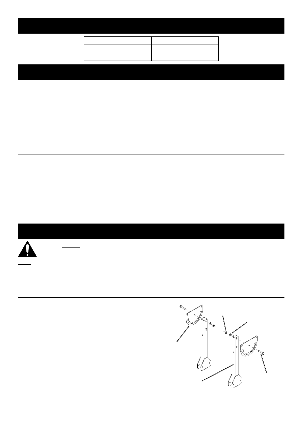
Support Leg Assembly
Attach the two Vertical Post-Angle Bracket
assemblies from the previous step to the two
Support Legs (13) using four Washers (7),
Nuts (8) and Bolts (12). See Figure B.
Vertical Post – Angle Bracket
Assemblies
Nut (8)
Bolt (12)
Washer (7)
Figure B
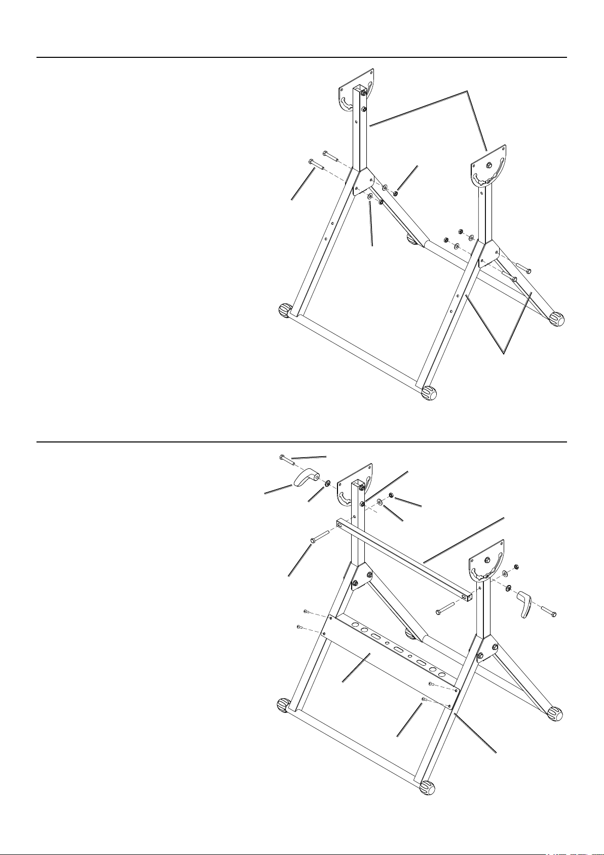
Tool Hanger – Support Brace – Angle Handle Assembly
1. Attach the Tool Hanger (16)
to the Support Leg which has
four threaded holes using four
Bolts (15). See Figure C.
2. Attach the Support Brace (21) to the
Vertical Posts using two Washers (7),
Nuts (8) and Bolts (22). See Figure C.
3. Insert a Bolt (12) through the back of
each of the two Angle Adjustment
Handles (10). Slide a Washer (11) over
each Bolt with the cupped side of the
Washer against the Handle. Insert the
Bolts through the Angle Brackets and
thread into the nut welded to the Vertical
Post. See Figure C.
Angle
Adjustment
Handle (10)
Bolt (22)
Bolt (12)
Washer
(11)
Tool
Hanger
(16)
Welded nut for
Handle Bolt
Nut (8)
Washer (7)
Support Legs (13)
Support
Brace (21)
Figure C
Bolt (15)
Support Leg (13)
Page 3For technical questions, please call 1-888-866-5797.Item 61369
 Loading...