

Harbor Freight Tools 61229 Owner's Manual
Owner’s Manual & Safety Instructions
Save This Manual Keep this manual for the safety warnings and precautions, assembly,
operating, inspection, maintenance and cleaning procedures. Write the product’s serial number in the
back of the manual near the assembly diagram (or month and year of purchase if product has no number).
Keep this manual and the receipt in a safe and dry place for future reference.
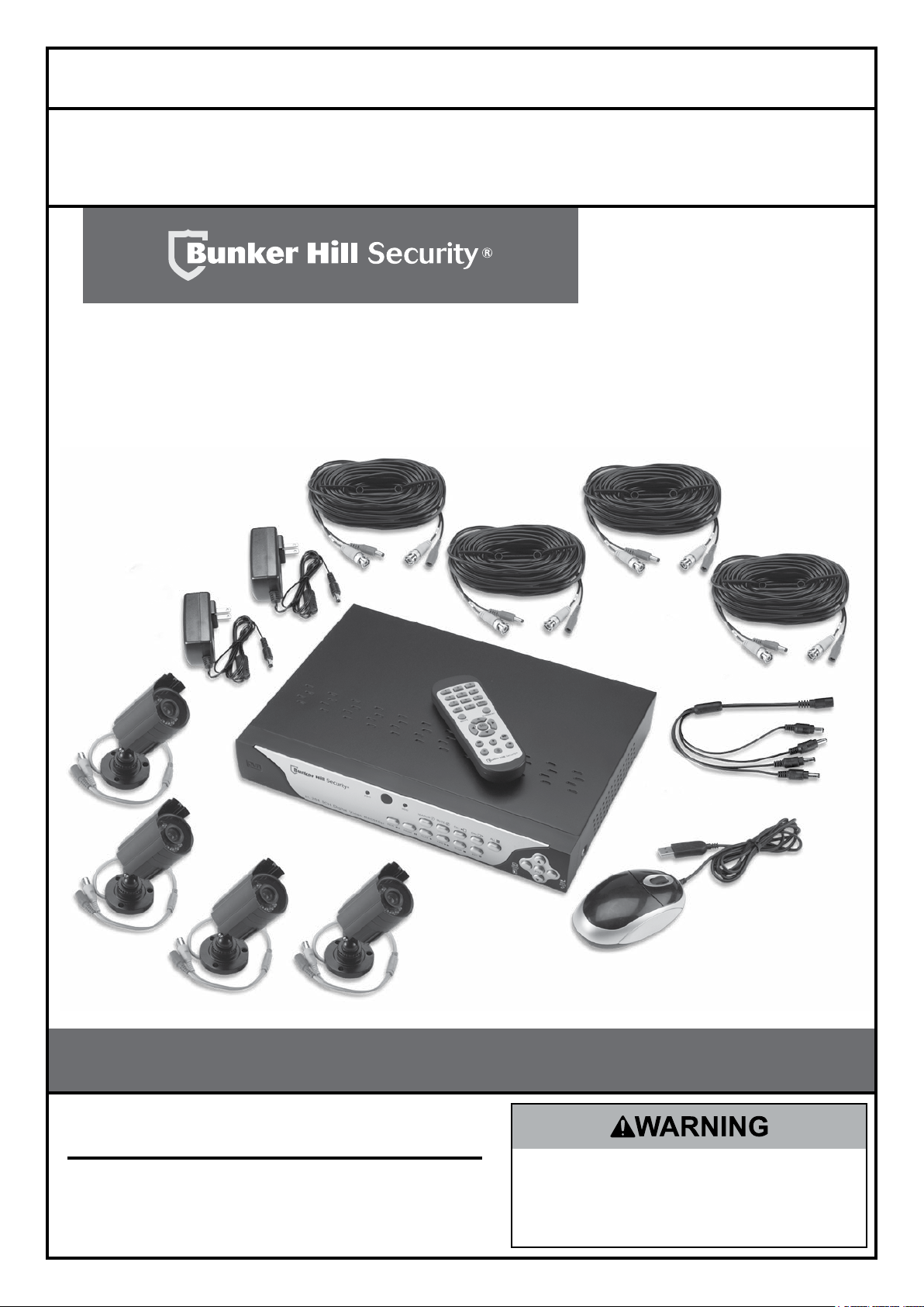
8-Channel
Surveillance DVR
Visit our website at: http://www.harborfreight.com
Email our technical support at: tech@harborfreight.com
When unpacking, make sure that the product is intact
and undamaged. If any parts are missing or broken,
please call 1-800-444-3353 as soon as possible.
Copyright© 2013 by Harbor Freight Tools®. All rights reserved.
No portion of this manual or any artwork contained herein may be reproduced in
any shape or form without the express written consent of Harbor Freight Tools.
Diagrams within this manual may not be drawn proportionally. Due to continuing
improvements, actual product may differ slightly from the product described herein.
Tools required for assembly and service may not be included.
ITEM 61229
Read this material before using this product.
Failure to do so can result in serious injury.
SAVE THIS MANUAL.
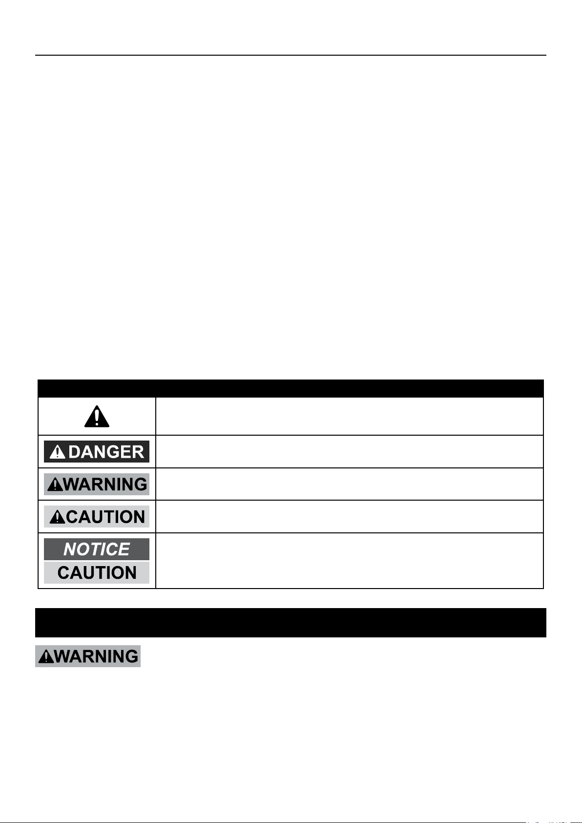
Table of Contents
Safety ......................................................... 3
Specifications ........................................... 5
Set up - Before Use .................................. 6
Quick Start Guide Flow Charts ................ 8
DVR Equipment Connections ................. 12
DVR Settings ............................................ 15
Pop-Up Menu .......................................... 15
Main Menu ............................................... 15
Main Menu Map ....................................... 16
Main Settings ........................................... 17
Recording Schedule ................................ 18
Motion Detection...................................... 19
Users ....................................................... 20
System Information.................................. 21
Display Settings ....................................... 21
Display Output ......................................... 22
Privacy Zones .......................................... 22
Recording Parameters............................. 23
Video Stream ........................................... 23
Maintain Hard Drive ................................. 24
Alerts........................................................ 24
DVR Operating Instructions .................... 2
Search Recordings .................................. 25
Backup Recordings ................................. 26
Format Drives .......................................... 27
PTZ Camera ............................................ 27
Local Area Network Setup ...................... 28
Set up Remote Video Stream .................. 29
Set up Email Capability ........................... 29
Set up Smartphone Capability ................. 29
Wide Area Network Setup ....................... 30
Software ................................................... 31
DVR Client ............................................... 31
Video Player ............................................ 32
MAC Record Player ................................. 32
AVI Generator .......................................... 32
Smartphone ............................................. 32
Maintenance Instructions ....................... 33
Troubleshooting ...................................... 34
Parts List .................................................. 35
Warranty ................................................... 36
WARNING SYMBOLS AND DEFINITIONS
This is the safety alert symbol. It is used to alert you to potential
personal injury hazards. Obey all safety messages that follow
this symbol to avoid possible injury or death.
Indicates a hazardous situation which, if not avoided,
will result in death or serious injury.
Indicates a hazardous situation which, if not avoided,
could result in death or serious injury.
Indicates a hazardous situation which, if not avoided,
could result in minor or moderate injury.
Addresses practices not related to personal injury.
IMPORTANT SAFETY INFORMATION
Read all safety warnings and instructions.
Failure to follow the warnings and instructions may result in electric shock, fire and/or serious injury.
Save all warnings and instructions for future reference.
Page 2 For technical questions, please call 1-800-444-3353. Item 61229

Installation Precautions
1. Check federal, state and local surveillance laws
before installing video
and/or audio surveillance equipment.
2. Install only according to these instructions.
Improper installation can create hazards.
3. Do not overreach when installing this product.
Keep proper footing and balance at all times.
This enables better control in unexpected situations.
Use Precautions
1. This product is not a toy. Do not allow
children to play with or near this item.
2. Use as intended only.
3. Do not modify.
Electrical Safety
1. Power Adapter plugs must match
the outlet. Never modify the plug in
any way. Unmodified plugs and matching
outlets will reduce risk of electric shock.
2. Do not expose DVR unit to rain or wet
conditions. Water entering the DVR will
increase the risk of electric shock.
4. Wear ANSI-approved safety goggles
during installation.
5. Keep installation area clean and well lit.
6. Keep children and bystanders out of
the area during installation.
7. Do not install when tired or when under the
influence of alcohol, drugs or medication.
4. Maintain product labels and nameplates.
These carry important safety information.
If unreadable or missing, contact
Harbor Freight Tools for a replacement.
3. Do not abuse the cord. Never use the cord
for carrying, pulling or unplugging the
power tool. Keep cord away from heat, oil,
sharp edges or moving parts. Damaged or
entangled cords increase the risk of electric shock.
SAFETYOPERATIONNETWORK SETTINGS
Service
Have your DVR equipment serviced by a qualified repair person using only identical replacement parts.
This will ensure that the safety of the equipment is maintained.
Camera Safety Warnings
1. To prevent electric shock, do not attempt
to disassemble Camera. There are
no serviceable parts inside.
2. Use supplied Power Adapter only.
3. Do not expose the Power Adapter to rain
or wet conditions. Water entering the Power
Adapter will increase the risk of electric shock.
4. Do not abuse the Power Adapter cord. Never
use the cord for unplugging the plug from the
outlet. Keep cord away from heat, oil, sharp
edges or moving parts. Damaged or entangled
cords increase the risk of electric shock.
5. Handle Camera with care. Camera could be
damaged by improper handling or storage.
Page 3For technical questions, please call 1-800-444-3353.Item 61229
DVR Safety Warnings
1. Maintain adequate airflow around DVR.
2. Use supplied Power Adapter only.
SAFETY OPERATION NETWORKSETTINGS
3. Do not expose the Power Adapter or DVR
console to rain or wet conditions. Water
entering the Power Adapter or DVR console
will increase the risk of electric shock.
4. Do not abuse the Power Adapter cord. Never
use the cord for unplugging the plug from the
outlet. Keep cord away from heat, oil, sharp
edges or moving parts. Damaged or entangled
cords increase the risk of electric shock.
SAVE THESE INSTRUCTIONS.
Grounding
5. Maintain labels and nameplates on the unit.
These carry important safety information. If
unreadable or missing, contact Harbor
Freight Tools for a replacement.
6. WARNING: Handling the cord on this product will
expose you to lead, a chemical known to the State
of California to cause cancer, and birth defects or
other reproductive harm. Wash hands after handling.
(California Health & Safety Code § 25249.5, et seq.)
7. The warnings, precautions, and instructions
discussed in this instruction manual cannot
cover all possible conditions and situations
that may occur. It must be understood by the
operator that common sense and caution are
factors which cannot be built into this product,
but must be supplied by the operator.
TO PREVENT ELECTRIC SHOCK AND DEATH FROM
INCORRECT GROUNDING WIRE CONNECTION:
Check with a qualified electrician if you are in doubt as to whether the outlet is properly
grounded. Do not modify the power cord plug provided with the tool. Never remove the
grounding prong from the plug. Do not use the tool if the power cord or plug is damaged. If damaged, have
it repaired by a service facility before use. If the plug will not fit the outlet, have a proper outlet installed by
a qualified electrician.
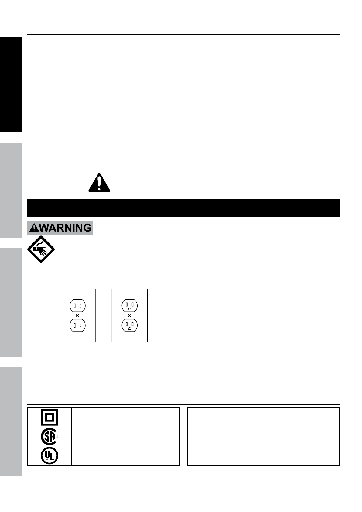
1. The included Power Adapters do
not require grounding.
2. The Power Adapters may be used in
either of the 120 volt outlets shown in the
preceding illustration. (See Figure A.)
Figure A: Outlets for 2-Prong Plug
Extension Cords
Note: Do not use an extension cord with the Power Adapters.
Symbology
Double Insulated
Canadian Standards Association
Underwriters Laboratories, Inc.
Page 4 For technical questions, please call 1-800-444-3353. Item 61229
V
~
A
Volts
Alternating Current
Amperes
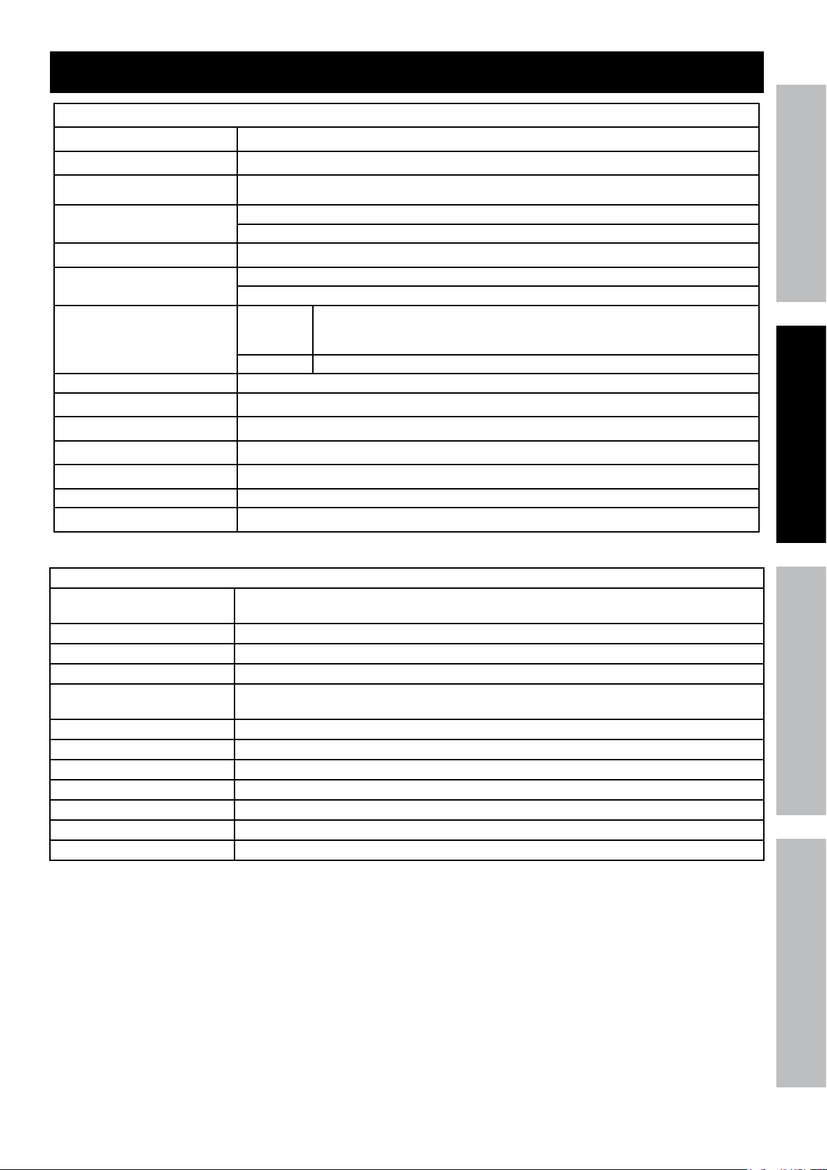
Specifications
DVR
Hard Drive 500 GB
Video Standard NTSC / PAL
Video Codec H.264
Video I/O
Audio Codec G.711
Audio I/O
Recording
Recording Mode Manual / Schedule / Motion Detection / Remote
Motion Detection Selectable Area and Sensitivity Detection
PTZ Interface RS485 - Supports Pelco-D/P camera (sold separately)
Network Interface RJ-45 10m/100m Ethernet Interface
USB Interface USB 2.0
DVR Input Rating 12VDC / 2A
Operating Temperature 32º - 131ºF
Input: 8 BNC
Output: 2 BNC / 1 VGA
Input: 1 RCA
Output: 1 RCA
CIF: 352 x 240;
Resolution
Frame Rate Up to 30 fps each channel
HD1: 704 x 240;
D1: 704 x 480
Cameras
Lens Types 2 Cameras with fixed 6 mm lenses
2 Cameras with fixed 3.6 mm lenses
Horizontal Resolution 400 TVL
Effective Pixels 648H x 488V
Night Vision Type Infrared LEDs with Low Light Sensor
Image Type Daylight: Color
Infrared: Black & White
Infrared Wavelength 850nm
Infrared Distance 30 ft. (indoors)
Ingress Protection Rating IP65 - Protected from low pressure water jets
Video Connector BNC
Camera Input Rating 12VDC / 500 mA
Cable Length 60 ft.
Operating Temperature 14° - 122°F
SAFETYOPERATIONNETWORK SETTINGS
Page 5For technical questions, please call 1-800-444-3353.Item 61229
Set up - Before Use:
Read the ENTIRE IMPORTANT SAFETY INFORMATION section at the beginning of this
manual including all text under subheadings therein before set up or use of this product.
SAFETY OPERATION NETWORKSETTINGS
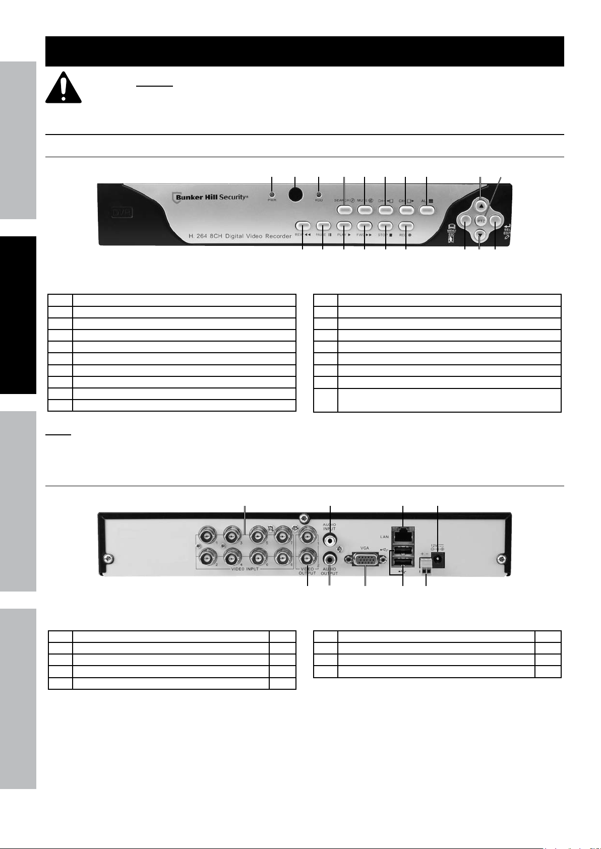
Components and Controls
DVR Front Panel
1 Green Power Indicator
2 Remote Control IR Receiver
3 Red Hard Disk Drive Activity Indicator
4 Search Recordings
5 Mute
6 Previous Channel
7 Next Channel
8 Toggle 4 and 9 Screen Displays
9 Menu Up / PTZ Up
10 PTZ Control Mode
Note: Controls for PTZ mode are italicized.
1
Figure B
4 5
3
2
12 13 14
11 Rewind / Activate Controls
12 Pause
13 Play
14 Fast Forward
15 Stop
16 Start Manual Recording
17 Open Menu / Escape / PTZ Left
18 Menu Down / PTZ Down
19 Conrm Selection / Edit Selected Setting / PTZ
Right
6 7
15
8
16 19
1711
9 10
18
DVR Back Panel
1
1 BNC Video Input 8
2 RCA Audio Input 1
3 RJ45 LAN Ethernet Port 1
4 12VDC Power Input 1
5 BNC Video Output 2
5
Figure C
2
6
6 RCA Audio Output 1
7 VGA Port 1
8 USB 2.0 Port 2
9 RS485 PTZ Connector 1
7 8 9
3 4
Page 6 For technical questions, please call 1-800-444-3353. Item 61229
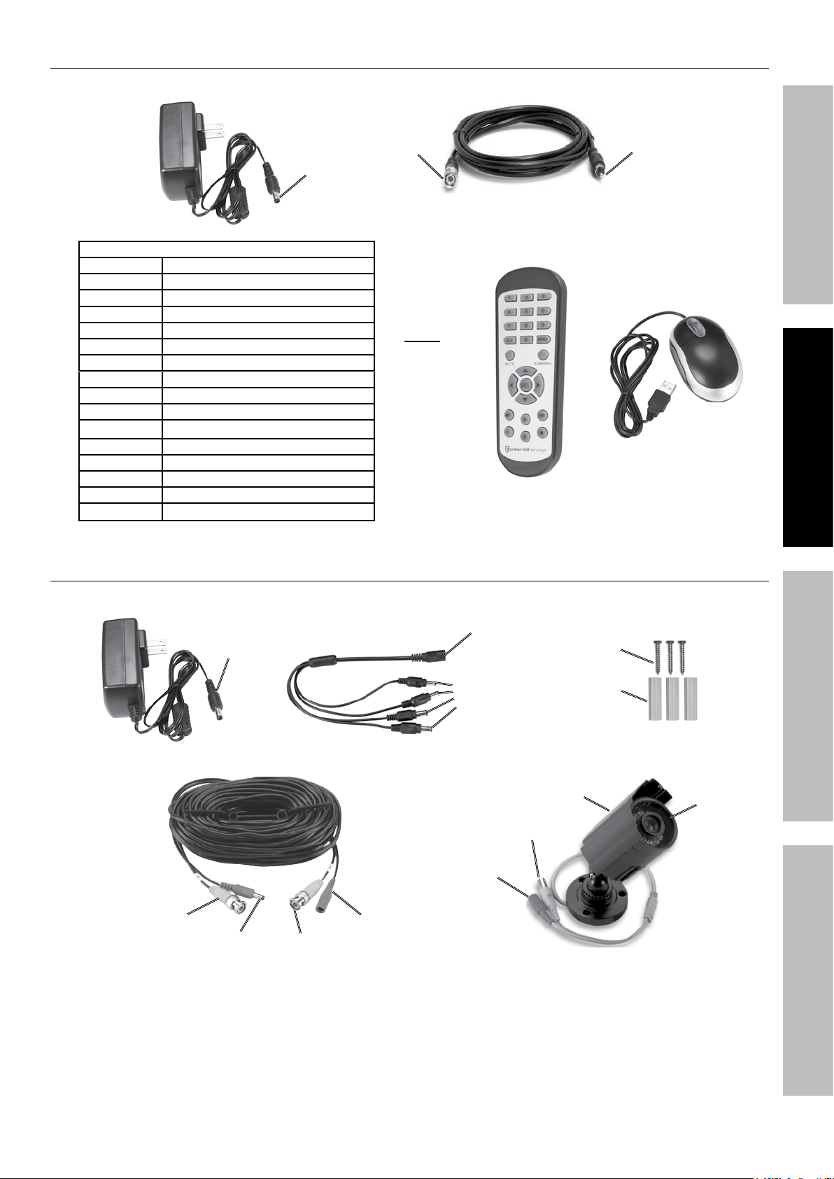
DVR Accessories
Power Adapter
(to DVR)
Remote Control Functions
1 - 8 Select Channel
ALL Toggle 4 and 9 Screen Displays
MENU Open Menu
MUTE Mute
SUBMENU Open Pop-Up Menu
▲ Menu Up
▼ Menu Down
◄ Menu Left
► Menu Right
SEL Confirm Selected Operation
◄◄ Rewind
► Play / Search Records
►► Fast Forward
● Record
ll Pause
■
Stop
Power
BNC
(to DVR)
Note:
2 AAA
batteries
included.
Figure D
BNC to RCA Cable
RCA (to
Monitor)
SAFETYOPERATIONNETWORK SETTINGS
Remote
Mouse
Camera and Accessories
Power Adapter
Power
(to Splitter)
Cable - 60 ft.
Video
(from Camera)
Power
(to Camera)
Video
(to DVR)
Power Splitter
Power
(from Splitter)
Figure E
Power
(from Adapter)
Power
(to Cables)
Video
(to Cable)
Power
(from Cable)
Mounting Hardware
Screws
Anchors
Camera
Hood
Lens
Page 7For technical questions, please call 1-800-444-3353.Item 61229
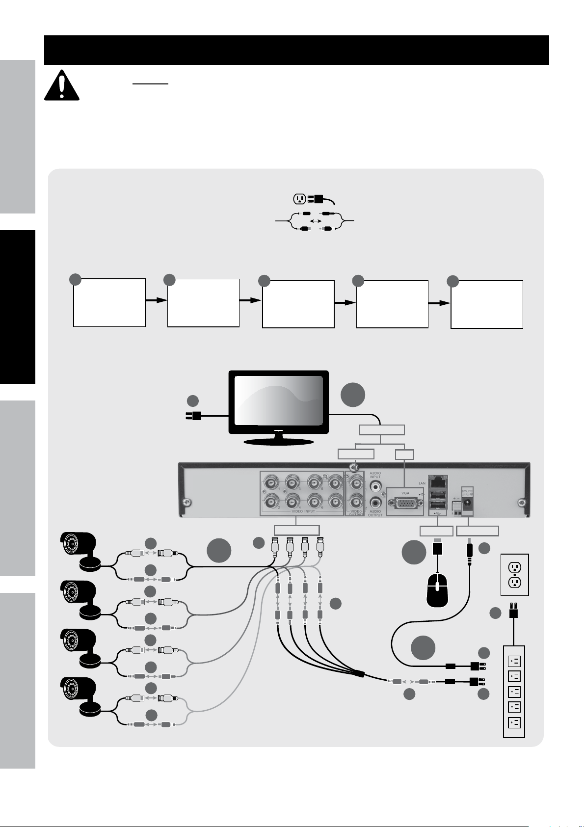
Quick Start Guide Flow Charts
Read the ENTIRE IMPORTANT SAFETY INFORMATION section at the beginning of this manual
including all text under subheadings therein before set up or use of this product.
SAFETY OPERATION NETWORKSETTINGS
Use the following flow charts to help make the cable connections, navigate the system and set up or change the unit
settings. Refer to the individual setup sections in this manual for detailed instructions on specific tasks.
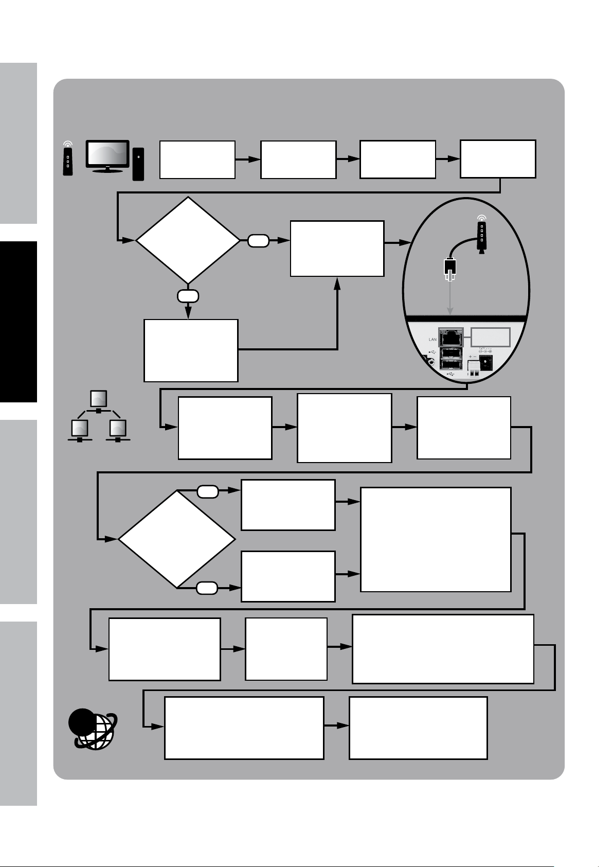
INITIAL SETUP
Physical Connections
A
Connect
Monitor
B
Connect
Cameras
D1
C
Connect
Mouse
D
A
Video Output
BNC/RCA
See Page 12
Connect
Power
VGA
1
E
Mount
Cameras
Video Input
B1
B3
B
B2
B1
B2
B1
B2
B1
B2
Page 8 For technical questions, please call 1-800-444-3353. Item 61229
Note: Monitor and
Surge Protector
sold separately.
B4
C
B5
USB Port
D
Power Input
D2
D5
D3
D4
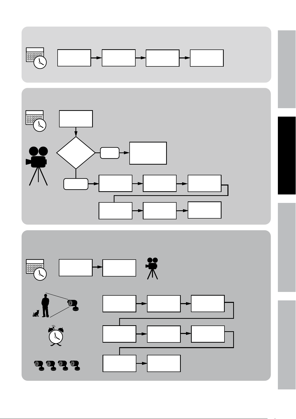
2
Set Date and Time
In DVR
Main Menu
Select System
Set Recording Mode
Set Date and
Time above
Which
Recording
mode?
Scheduled
Manual
In DVR
Main Menu
select Record
Select
General
See Main Settings on Page 17
Set Date and
Time
See Recording Schedule on Page 18
Press REC on
front of DVR -
red light will
flash
Select
Schedule
Click Apply
then OK
SAFETYOPERATIONNETWORK SETTINGS
3
Select Channel
and Day of
Week
Select boxes
for Normal and
Motion
Motion Detection Settings
Set Date and
Time above
Set Recording
Mode above
In DVR
Main Menu
Select Alarm
Select Area
Repeat for all
Days and all
Channels
See Motion Detection on Page 19
Select
Motion
Set Sensitivity
Level
Click Apply
then OK
Select
Channel
Select which
Channels
will record
4
Set Buzzer for
audible alarm
Click Apply
then OK
Page 9For technical questions, please call 1-800-444-3353.Item 61229
SAFETY OPERATION NETWORKSETTINGS
Local Area Network (LAN) Setup
In DVR
Main Menu
Select System
Do you have a
Windows® PC with
Internet Explorer®
and a Router?
NO
STOP
Ensure you have a
Windows® PC with
Internet Explorer®
and a Router before
proceeding.
From DVR Main Menu
select
Network > Network
Type = Static
YES
Select
Users
Connect DVR to
Router via
Ethernet Cable
(Sold Separately)
On PC, go to Start
Menu, click Run.
In DOS window
type “cmd”, click OK.
type “ipconfig”
press ENTER
Set User Name
and Password
See Page 28
Find the Router’s LAN
Write down:
1. Subnet Mask
2. Default Gateway
(Router’s IP Address)
Click Apply
then OK
Ethernet
Connection
@
NO
Create New IP
Address:
Are last 3 digits of
Default Gateway
between 0-99?
YES
Click Apply then OK
to save changes.
Click Exit, DVR will prompt
restart. Click OK.
Allow ActiveX Control to install.
You may need to adjust the settings in
Internet Explorer® by adding the http
address to Trusted Sites and modifying
ActiveX controls to allow installation.
Change last 3 digits
to a number between
200 and 255
Change last 3 digits
to a number between
100 and 255
After restart,
on DVR go to
Network > Network
to view settings.
In DVR Network > Network
change settings:
1. Client Port: 3000
2. HTTP Port: 3001
3. New IP Address
4. Subnet Mask you wrote down
5. Default Gateway you wrote down
6. DNS1 same as Gateway
Open Internet Explorer®.
In address bar, type in
DVR’s IP Address and HTTP Port:
http://xxx.xxx.xxx.xxx:3001
(where x = IP Address and 3001 = HTTP Port)
Press Enter.
After ActiveX Control installs,
Log in to DVR
with User Name and Password.
Page 10 For technical questions, please call 1-800-444-3353. Item 61229
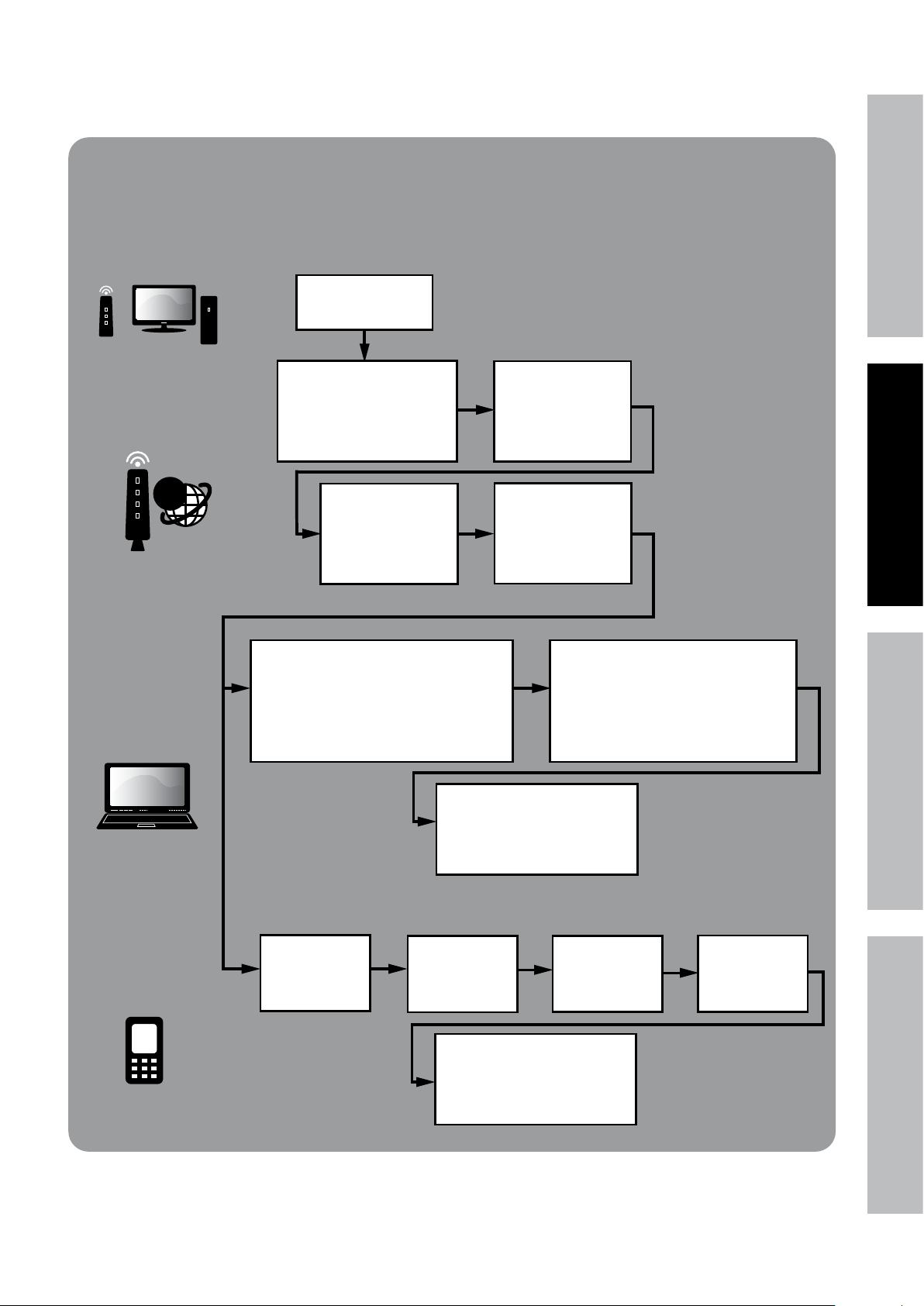
Wide Area Network (WAN) Setup
FOR ADVANCED USERS
Internet Setup for Remote Use
Set up LAN
according to
instructions above.
PORT FORWARDING
@
Open Internet Explorer®.
In address bar, type in
Default Gateway
(from LAN Setup above).
Example: xxx.xxx.xxx.xxx
Press Enter.
Set start port to 3000
and end port to 3002.
Set up both UDP and
TCP protocols if the
option is given.
Log in to the Router
and go to
Port Forwarding or
Applications and
Gaming.
Find the Router’s IP
Address by going to
whatsmyip.com.
Write it down.
See Page 30
SAFETYOPERATIONNETWORK SETTINGS
REMOTE
COMPUTER
ACCESS
SMARTPHONE
ACCESS
Open Internet Explorer®. In address bar,
and HTTP Port (from LAN Setup above):
(where x = IP Address and 3001 = HTTP Port)
Select Network
On remote computer,
type in Router’s IP Address
http://xx.xxx.xxx.xxx:3001
Press Enter.
In DVR
Main Menu
then Mobile
After ActiveX Control installs,
with User Name and Password
(from LAN Setup above).
Set User Name
and Password
Insert supplied CD
into computer and look in
Mobile Software
folder for instructions.
Log in to DVR
Set Mobile Port
Allow ActiveX Control to install.
You may need to adjust the settings
in Internet Explorer® by adding the
http address to Trusted Sites and
modifying ActiveX controls to allow
to 3002
installation.
Click Apply
then OK
Page 11For technical questions, please call 1-800-444-3353.Item 61229
 Loading...