

Page 1
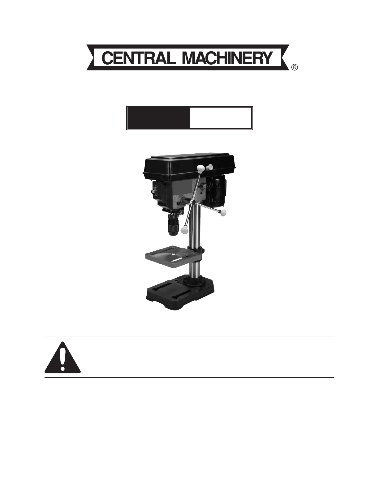
8” Drill Press
Model
44505
set uP anD OPerating instructiOns
Visit our website at: http://www.harborfreight.com
read this material before using this product.
Failure to do so can result in serious injury.
saVe this Manual.
Copyright© 2010 by Harbor Freight Tools®. All rights reserved. No portion of this manual or any artwork
contained herein may be reproduced in any shape or form without the express written consent of
Harbor Freight Tools. Diagrams within this manual may not be drawn proportionally. Due to continuing
improvements, actual product may differ slightly from the product described herein. Tools required for
assembly and service may not be included.
For technical questions or replacement parts, please call 1-800-444-3353.
Manual revised 10f
Page 2

cOntents
iMPOrtant saFetY
inFOrMatiOn .................................3
general tOOl saFetY Warnings . 3
grOunDing instructiOns ..........5
110-120 V~ grOunDeD tOOls:
tOOls With three PrOng Plugs 5
Drill Press saFetY Warnings ..... 5
Maintenance anD serVicing ...12
cleaning, Maintenance, anD
lubricatiOn ....................................12
trOubleshOOting ........................... 14
Parts lists anD DiagraMs ......15
heaD asseMblY Parts list ........... 15
heaD asseMblY DiagraM .............. 16
Parts list anD DiagraM a -
PulleY anD sPinDle ..................... 17
sPeciFicatiOns ...............................8
unPacking .......................................8
instructiOns FOr Putting
intO use .........................................8
asseMblY/MOunting ......................... 8
OPerating instructiOns .........10
tOOl set uP ....................................... 10
WOrk Piece anD WOrk area
set uP ...............................................10
general OPerating
instructiOns ..................................11
Parts list anD DiagraM b -
chuck anD sPinDle shaFt ......... 18
Parts list anD DiagraM c -
base anD table ............................. 19
liMiteD 90 DaY WarrantY .........20
Page 2 For technical questions, please call 1-800-444-3353. SKU 44505
Page 3

saVe this Manual
Keep this manual for the safety warnings
and precautions, assembly, operating,
inspection, maintenance and cleaning
procedures. Write the product’s serial number
in the back of the manual near the assembly
diagram (or month and year of purchase if
product has no number). Keep this manual
and the receipt in a safe and dry place for
future reference.
iMPOrtant saFetY
inFOrMatiOn
in this manual, on the labeling, and
all other information provided with
this product:
this is the safety alert
symbol. it is used to alert
you to potential personal
injury hazards. Obey all
safety messages that follow
this symbol to avoid possible
injury or death.
Danger indicates a
hazardous situation
which, if not avoided, will result
in death or serious injury.
Warning indicates a
hazardous situation
which, if not avoided, could
result in death or serious injury.
nOtice is used to
address practices not
related to personal injury.
cautiOn, without the
safety alert symbol, is
used to address practices not
related to personal injury.
general tool safety Warnings
Warning read all safety warnings
and instructions. Failure to follow the
warnings and instructions may result
in electric shock, re and/or serious
injury.
save all warnings and instructions
for future reference.
KEEP GUARDS IN PLACE and in 1.
working order.
REMOVE ADJUSTING KEYS AND 2.
WRENCHES. Form habit of checking to
see that keys and adjusting wrenches
are removed from tool before turning it
on.
KEEP WORK AREA CLEAN. Cluttered 3.
areas and benches invite accidents.
DON’T USE IN DANGEROUS 4.
ENVIRONMENT. Don’t use power tools
in damp or wet locations, or expose them
to rain. Keep work area well lighted.
KEEP CHILDREN AWAY. All visitors 5.
should be kept safe distance from work
area.
cautiOn, used with
the safety alert
symbol, indicates a hazardous
situation which, if not avoided,
could result in minor or moderate
injury.
MAKE WORKSHOP KID PROOF 6.
with padlocks, master switches, or by
removing starter keys.
DON’T FORCE TOOL. It will do the job 7.
better and safer at the rate for which it
was designed.
Page 3For technical questions, please call 1-800-444-3353.SKU 44505
Page 4

USE RIGHT TOOL. Don’t force tool or 8.
attachment to do a job for which it was
not designed.
recOMMenDeD MiniMuM Wire
gauge FOr eXtensiOn cOrDs
(120 VOlt)
naMePlate
aMPeres
(at full load)
0 – 6 18 16 16 14
6.1 – 10 18 16 14 12
10.1 – 12 16 16 14 12
12.1 – 16 14 12 Do not use.
eXtensiOn cOrD
length
25’ 50’ 100’ 150’
table a
13.
DON’T OVERREACH. Keep proper
footing and balance at all times.
14.
MAINTAIN TOOLS WITH CARE. Keep
tools sharp and clean for best and safest
performance. Follow instructions for
lubricating and changing accessories.
DISCONNECT TOOLS before servicing;
15.
when changing accessories, such as
blades, bits, cutters, and the like.
REDUCE THE RISK OF 16.
UNINTENTIONAL STARTING. Make
sure switch is in off position before
plugging in.
USE PROPER EXTENSION CORD. 9.
Make sure your extension cord is in good
condition. When using an extension
cord, be sure to use one heavy enough
to carry the current your product will
draw. An undersized cord will cause a
drop in line voltage resulting in loss of
power and overheating. Table A shows
the correct size to use depending on
cord length and nameplate ampere
rating. If in doubt, use the next heavier
gauge. The smaller the gauge number,
the heavier the cord.
WEAR PROPER APPAREL. Do not wear 10.
loose clothing, gloves, neckties, rings,
bracelets, or other jewelry which may get
caught in moving parts. Nonslip footwear
is recommended. Wear protective hair
covering to contain long hair.
ALWAYS USE SAFETY GLASSES. Also 11.
use face or dust mask if cutting operation
is dusty. Everyday eyeglasses only have
impact resistant lenses, they are NOT
safety glasses.
SECURE WORK. Use clamps or a vise 12.
to hold work when practical. It’s safer
than using your hand and it frees both
hands to operate tool.
USE RECOMMENDED ACCESSORIES. 17.
Consult the owner’s manual for
recommended accessories. The use of
improper accessories may cause risk of
injury to persons.
NEVER STAND ON TOOL. Serious 18.
injury could occur if the tool is tipped
or if the cutting tool is unintentionally
contacted.
CHECK DAMAGED PARTS. Before 19.
further use of the tool, a guard or other
part that is damaged should be carefully
checked to determine that it will operate
properly and perform its intended
function – check for alignment of moving
parts, binding of moving parts, breakage
of parts, mounting, and any other
conditions that may affect its operation.
A guard or other part that is damaged
should be properly repaired or replaced.
DIRECTION OF FEED. Feed work into 20.
a blade or cutter against the direction of
rotation of the blade or cutter only.
NEVER LEAVE TOOL RUNNING
21.
UNATTENDED. TURN POWER OFF.
Don’t leave tool until it comes to a
complete stop.
Page 4 For technical questions, please call 1-800-444-3353. SKU 44505
Page 5

grOunDing instructiOns
tO PreVent
electric shOck
anD Death FrOM incOrrect
grOunDing Wire
cOnnectiOn
reaD anD FOllOW these
instructiOns:
3-pole receptacles that accept the tool’s
plug.
6.
Repair or replace damaged or worn cord
immediately.
110-120 V~ grounded tools: tools
with three Prong Plugs
In the event of a malfunction or 1.
breakdown, grounding provides a path
of least resistance for electric current
to reduce the risk of electric shock.
This tool is equipped with an electric
cord having an equipment-grounding
conductor and a grounding plug. The
plug must be plugged into a matching
outlet that is properly installed and
grounded in accordance with all local
codes and ordinances.
Do not modify the plug provided – if it will 2.
not t the outlet, have the proper outlet
installed by a qualied electrician.
Improper connection of the equipment-3.
grounding conductor can result in a risk
of electric shock. The conductor with
insulation having an outer surface that
is green with or without yellow stripes is
the equipment-grounding conductor. If
repair or replacement of the electric cord
or plug is necessary, do not connect the
equipment-grounding conductor to a live
terminal.
grounding
Pin
125 V~ 3-Prong Plug and Outlet
(for up to 125 V~ and up to 15 a)
This tool is intended for use on a circuit 7.
that has an outlet that looks like the one
illustrated above in 125 V~ 3-Prong
Plug and Outlet. The tool has a
grounding plug that looks like the plug
illustrated above in 125 V~ 3-Prong
Plug and Outlet.
The outlet must be properly installed and 8.
grounded in accordance with all codes
and ordinances.
Do not use an adapter to connect this 9.
tool to a different outlet.
Drill Press safety Warnings
For Your Own safety read instruction
Manual before Operating Drill Press
Wear eye protection.1.
Do not wear gloves, necktie, or loose 2.
clothing.
Check with a qualied electrician or 4.
service personnel if the grounding
instructions are not completely
understood, or if in doubt as to whether
the tool is properly grounded.
Use only 3-wire extension cords that 5.
have 3-prong grounding plugs and
Clamp workpiece or brace against 3.
column to prevent rotation.
Use recommended speed for drill
4.
accessory and workpiece material.
Page 5For technical questions, please call 1-800-444-3353.SKU 44505
Page 6

DO nOt OPerate With anY 5.
guarD DisableD, DaMageD, Or
reMOVeD.
The use of accessories or attachments 6.
not recommended by the manufacturer
may result in a risk of injury to persons.
When servicing use only identical
7.
replacement parts.
Only use safety equipment that has been 8.
approved by an appropriate standards
agency. Unapproved safety equipment
may not provide adequate protection.
Eye protection must be ANSI-approved
and breathing protection must be
NIOSH-approved for the specic hazards
in the work area.
Industrial applications must follow OSHA 9.
guidelines.
Maintain labels and nameplates on 10.
the tool. These carry important safety
information. If unreadable or missing,
contact Harbor Freight Tools for a
replacement.
Avoid unintentional starting. Prepare to 11.
begin work before turning on the tool.
• Arsenic and chromium from chemically
treated lumber
Your risk from these exposures varies,
depending on how often you do this type
of work. To reduce your exposure to
these chemicals: work in a well ventilated
area, and work with approved safety
equipment, such as those dust masks
that are specially designed to lter out
microscopic particles. (California Health
& Safety Code § 25249.5, et seq.)
WARNING: Handling the cord on this 14.
product will expose you to lead, a
chemical known to the State of California
to cause cancer, and birth defects or
other reproductive harm. Wash hands
after handling. (California Health &
Safety Code § 25249.5, et seq.)
The warnings, precautions, and 15.
instructions discussed in this instruction
manual cannot cover all possible
conditions and situations that may occur.
It must be understood by the operator
that common sense and caution are
factors which cannot be built into this
product, but must be supplied by the
operator.
People with pacemakers should 12.
consult their physician(s) before use.
Electromagnetic elds in close proximity
to heart pacemaker could cause
pacemaker interference or pacemaker
failure.
WARNING: Some dust created by power
13.
sanding, sawing, grinding, drilling, and
other construction activities, contains
chemicals known [to the State of
California] to cause cancer, birth defects
or other reproductive harm. Some
examples of these chemicals are:
• Lead from lead-based paints
• Crystalline silica from bricks and
cement or other masonry products
Page 6 For technical questions, please call 1-800-444-3353. SKU 44505
Vibration safety
This tool vibrates during use. Repeated
or long-term exposure to vibration may
cause temporary or permanent physical
injury, particularly to the hands, arms
and shoulders. To reduce the risk of
vibration-related injury:
Anyone using vibrating tools regularly 1.
or for an extended period should rst
be examined by a doctor and then have
regular medical check-ups to ensure
medical problems are not being caused
or worsened from use. Pregnant
women or people who have impaired
blood circulation to the hand, past hand
injuries, nervous system disorders,
Page 7

diabetes, or Raynaud’s Disease should
not use this tool. If you feel any medical
or physical symptoms related to vibration
(such as tingling, numbness, and white
or blue ngers), seek medical advice as
soon as possible.
Do not smoke during use. Nicotine
2.
reduces the blood supply to the hands
and ngers, increasing the risk of
vibration-related injury.
Wear suitable gloves to reduce the 3.
vibration effects on the user.
4.
Use tools with the lowest vibration when
there is a choice between different
processes.
Include vibration-free periods each day 5.
of work.
Grip tool as lightly as possible (while still 6.
keeping safe control of it). Let the tool
do the work.
To reduce vibration, maintain the tool 7.
as explained in this manual. If any
abnormal vibration occurs, stop use
immediately.
saVe these
instructiOns.
Page 7For technical questions, please call 1-800-444-3353.SKU 44505
Page 8

sPeciFicatiOns
Electrical Input 120 V~, 60 Hz, 1/3 HP (3.6 A)
Motor Speed 1750 RPM (No Load)
Spindle Speeds 620, 1100, 1720, 2340, and 3100 RPM
Spindle Stroke 2”
Base 11-1/8” x 6-3/8”; Slot: 9/16”
Throat Depth 4” (of 8” swing)
Chuck 1/2”, keyless
Table Rotation 360°; Tilt: 45° (left and right)
Table Size 6-5/8” x 6-3/8”
Table Slot 5/8”
e105017
unPacking
When unpacking, make sure that the
item is intact and undamaged. If any parts
are missing or broken, please call Harbor
Freight Tools at 1-800-444-3353 as soon as
possible.
Assembly hardware is located in
separate bags/boxes. Each contains the
necessary parts for each assembly step.
Remove all packing and protective material
from the Drill Press components.
instructiOns FOr Putting
intO use
read the entire iMPOrtant
saFetY inFOrMatiOn
section at the beginning of this
manual including all text under
subheadings therein before set up
or use of this product.
tO PreVent
seriOus injurY
FrOM acciDental
OPeratiOn:
turn the Power switch of the tool
to its “OFF” position and unplug
the tool from its electrical outlet
before assembling or making any
adjustments to the tool.
note: For additional information regarding the
parts listed in the following pages, refer
to the Assembly Diagram near the end of
this manual.
assembly/Mounting
note: Assembly hardware is located in
separate bags/boxes.
Position the 1. base (C4) on a level and
sturdy table for mounting.
It is recommended to bolt the Base to the
table using appropriate hardware (not
supplied).
Place the
2. support tube (C3) on the
Base, aligning the mounting holes.
Insert three large Hex Screws (C5) into
3.
the mounting holes and tighten.
Install the 4. table support (C1), with
attached Table (C7), over the Support
Tube (C3) and slide it down. Hand
tighten the Lock Handle Support (C2).
cautiOn! avoid injuries. the next step
involves lifting the head assembly
onto the support tube. the head
assembly is heavy. have someone
help you lift this assembly into place.
guard (a5)
Motor
adjusting
knob (10)
Feed
knob (12)
5. Using two people, lift the head (1)
assembly up and onto the Support Tube
(C3).
Slide it down on the Column Tube as
far as it will go. Align it so that it faces
straight forward, inline with the Base.
knob
(a2)
set
screws
(11)
Page 8 For technical questions, please call 1-800-444-3353. SKU 44505
Page 9

Thread in two Set Screws (11), into the 6.
side of the Head (1) and tighten.
7.
Attach Knob (A2) to the (top) pulley
Guard (A5) using Pan Head Screw (A3).
Adjust 8. belt (a4) tension:
Open the pulley Guard (A5) to expose a.
the Belt.
b.
Turn the Motor Adjusting Knob (10)
counterclockwise to loosen Belt
Tension.
Push the Motor backward, tightening the c.
Belt on the pulleys, and hold in place.
d.
Turn the Motor Adjusting Knob
clockwise to tighten the Belt in place.
Refer to the chart inside the Guard lid to e.
select speed and belt locations.
Deection
Distance
Tap the nose of the Chuck lightly with d.
a piece of wood to securely set the
Chuck.
Screw (C6)
11. Verify that the Table (C7) is square (90
degrees) to the Head Assembly and drill
bit.
Secure a three inch drill bit in the Chuck a.
(hand tighten, no chuck key is required).
Raise the Table to within four inches of b.
the Chuck.
Place the long side of a combination c.
square on the Table.
note:
To test the proper belt tension, push in
on the center of each belt at its center. It
should move only 1/2 inch (in or out).
cautiOn! Overtightening the belts can
cause the motor to bind, and not start.
it can also damage Motor bearings.
Thread the 9. Feed knobs (12) and rods
(13) onto the Pinion Shaft (14) and
tighten them.
Install the 10. chuck (b8):
Thoroughly clean the tapered hole in the a.
Chuck and the Spindle Shaft (B7) of all
dirt, grease, oil, and protective coatings
(paint thinner may be necessary).
Slide the Chuck onto the Spindle Shaft.b.
Turn the Chuck sleeve clockwise and c.
open the jaws completely.
Align the short side of the square to the d.
drill bit.
If the Table is not square to the bit, e.
loosen Screw (C6) with a wrench.
Rotate the Table until it is square to the f.
bit.
Retighten the Screw (C6).g.
Install Light Bulb: 12.
Install light bulb (not more than 5W)
into socket, then install and tighten the
socket cover clockwise.
OPerating instructiOns
read the entire iMPOrtant
saFetY inFOrMatiOn
section at the beginning of this
manual including all text under
subheadings therein before set up
or use of this product.
Page 9For technical questions, please call 1-800-444-3353.SKU 44505
Page 10

tool set up
tO PreVent
seriOus injurY
FrOM acciDental
OPeratiOn:
turn the Power switch of the tool
to its “OFF” position and unplug
the tool from its electrical outlet
before performing any
inspection, maintenance, or
cleaning procedures.
Turn the Hex Nuts (31) down until they 5.
touch the Feed Wheel stop.
tilting the table
Loosen Screw (C6) under the Table 1.
assembly with a wrench.
Rotate the Table to the desired angle. 2.
The scale can be used to approximate
the angle.
3.
Retighten the Screw.
tO PreVent seriOus injurY:
DO nOt OPerate With anY
guarD DisableD, DaMageD,
Or reMOVeD.
setting the Depth scale to Drill to a
Specied Depth
Make sure the Drill Press is OFF and 1.
Power Cord (33) is unplugged. Secure
the workpiece to the Table.
Spring
Cap
(29)
Hex
Nuts
(30)
Pointer
(32)
Hex
Nuts
(31)
Work Piece and Work area set up
Designate a work area that is clean and 1.
well-lit. The work area must not allow
access by children or pets to prevent
distraction and injury.
Route the power cord along a safe 2.
route to reach the work area without
creating a tripping hazard or exposing
the power cord to possible damage. The
power cord must reach the work area
with enough extra length to allow free
movement while working.
Clamp workpiece or brace against 3.
column to prevent rotation.
There must not be objects, such as utility 4.
lines, nearby that will present a hazard
while working.
Notch
2. Mark the desired hole depth on the side
of the workpiece. Also view the depth
indicator Pointer (32).
Loosen the Hex Nuts (31) and screw 3.
both toward the top of Stop Rod (B12).
Turn the Feed Wheel counterclockwise 4.
to bring the tip of the drill bit down, next
general Operating instructions
Secure the tool to a supporting structure 1.
before use.
Make sure the Drill Press is OFF and the
2.
Power Cord (33) is unplugged. Loosen
the Lock Handle Support (C2) and adjust
the Table height to accommodate the
workpiece being drilled. Retighten Lock
Support Handle.
to the hole depth mark.
Page 10 For technical questions, please call 1-800-444-3353. SKU 44505
Page 11

Open the Chuck (B8) and insert the drill 3.
bit in the center.
Hand tighten the Chuck securely.
Secure the workpiece (and backup 4.
material) to the Table using a vise and/or
clamp.
The workpiece sits on the backup
material which in typically a scrap piece
of wood used to stabilize the workpiece.
It also helps the drill make a cleaner
hole. To keep it from spinning, have it
touching the left side of the Column.
Bring the drill bit down with the Feed 5.
Knob (12) to where the hole is to be
drilled.
Make minor workpiece alignment
adjustments.
Plug the Power Cord (33) into an 6.
electrical outlet.
Insert the Switch Key (24) into the 7.
Locking Switch (21).
Warning: Wear an ANSI-approved full face
shield while drilling.
Push the Switch up to turn the Motor ON.8.
Pull down on the Feed Knob and slowly 9.
drill the hole into the workpiece.
Warning: If the drill bit grabs and spins the
workpiece, do not attempt to stop the
spinning with your hands. Step back,
and push the Switch down to the OFF
position. Wait for the spindle to stop
turning before dislodging the workpiece.
When the drilling is complete, press the 10.
Switch to the OFF position and remove
the Switch Key (Keep the Switch Key in
a safe place).
To prevent accidents, turn off the tool 11.
and disconnect its power supply after
use.
Page 11For technical questions, please call 1-800-444-3353.SKU 44505
Page 12

Maintenance anD
removing the chuck and spindle shaft
serVicing
Procedures not specically
explained in this manual must
be performed only by a qualied
technician.
tO PreVent
seriOus injurY
FrOM acciDental
OPeratiOn:
turn the Power switch of the tool
to its “OFF” position and unplug
the tool from its electrical outlet
before performing any
inspection, maintenance, or
cleaning procedures.
tO PreVent seriOus injurY
FrOM tOOl Failure:
Do not use damaged equipment.
if abnormal noise or vibration
occurs, have the problem
corrected before further use.
cleaning, Maintenance, and
lubrication
beFOre each use,1. inspect the
general condition of the tool. Check for
loose hardware, misalignment or binding
of moving parts, cracked or broken parts,
damaged electrical wiring, and any
other condition that may affect its safe
operation.
aFter use,2. wipe external surfaces of
the tool with clean cloth.
3. Warning! if the supply cord of
this power tool is damaged, it must be
replaced only by a qualied service
technician.
During this procedure, refer to the Chuck
and Spindle Assembly Drawing.
1.
Pull the Feed Wheel counterclockwise
and hold the Chuck at a depth of three
inches.
Align the key holes in the Spindle Shaft
2.
(B7) and the Quill Tube (B3) by turning
the Chuck by hand.
Insert a Wedge Drift Key (not supplied) 3.
into the key holes.
Place a bundled cloth or basket below
4.
the Chuck to catch it when it falls.
Lightly tap the Wedge Drift Key with a
rubber mallet until the Spindle Shaft falls
out of the Quill Tube.
installing the chuck and spindle shaft
Using a clean cloth, wipe the tapered 1.
surfaces on the Spindle Shaft (B7).
Slide the Spindle Shaft and Chuck 2.
assembly up and into the Quill Tube
(B3).
At the same time, turn the assembly until
the rectangular end of the Spindle Shaft
slips into the notch on the Quill Tube.
Warning! in the previous step, if the
spindle shaft is not properly set in
the Quill Tube notch, it may y out
during operation.
Loosen the Lock Handle Support (C2) 3.
and raise the Table (C7) about three
inches below the Chuck.
Turn the Chuck sleeve clockwise to open 4.
the jaws completely.
Pull the Feed Knob counterclockwise 5.
and force the Chuck against the Table
until the Spindle Shaft is secure.
Page 12 For technical questions, please call 1-800-444-3353. SKU 44505
Page 13

adjusting the Feed Wheel return tension
spring
cautiOn! Wear an ansi-approved full
face shield during this procedure.
Move the Chuck to its uppermost 1.
position.
Loosen Hex Nuts (31) and move both to
2.
the lowermost position.
This will keep the Chuck from falling
during this adjustment.
Insert a screwdriver in the lower-front 3.
notch of the Spring Cap (29).
Hold it in place and, using a wrench,
remove the (outer) Hex Nut (30) only.
4.
With the screwdriver still in place, loosen
the (inner) Hex Nut (30) until the Spring
Cap notch disengages from the Spring
Retainer (27) -- about 1/8 inch.
8.
Pull the Feed Knob and check the spring
tension, making sure the up movement is
smooth and complete.
From one inch down, the Chuck should
return to its uppermost position. If more
tension is required, repeat steps.
Replace the (outer) Hex Nut and tighten 9.
on top of the (inner) Hex Nut.
Do not overtighten.
If the (up/down) movement is restricted, 10.
slightly loosen the (inner) Hex Nut, and
retighten the (outer) Hex Nut.
Spring
Cap
(29)
Hex
Nuts
(30)
Notch
Pointer
(32)
Hex
Nuts
(31)
5. Turn the screwdriver counterclockwise
and engage the next Spring Cap notch.
Leave the screwdriver in place.
Tighten the (inner) Hex Nut just enough 6.
to engage the notch.
If this Hex Nut is too tight, it will
restrict (up and down) Chuck-Spindle
movement.
Loosen and screw the Hex Nuts (31) to 7.
the top of the Stop Rod (B12).
Page 13For technical questions, please call 1-800-444-3353.SKU 44505
Page 14

troubleshooting
Problem Possible causes likely solutions
Tool will not start. Cord not connected.1.
No power at outlet. 2.
Internal damage or wear.3.
Tool operates slowly. Extension cord too long or wire size
too small.
Performance
decreases over time.
Excessive noise or
rattling.
Overheating. Forcing machine to work too fast.1.
Drill bit burns or
smokes
Drill bit wobbles Bent bit1.
Feed Wheel returns
slowly, or too fast
Drill bit binds Workpiece pinching drill bit
Accessory dull or damaged.
1.
Carbon brushes worn or 2.
damaged.
Belt too loose (slipping) or too 1.
tight (bearing damage).
Spindle dry2.
Loose spindle pulley3.
Loose motor pulley4.
Internal damage or wear.5.
Accessory misaligned.2.
Accessory dull or damaged. 3.
Blocked motor housing vents. 4.
Motor being strained by long or 5.
small diameter extension cord.
Incorrect spindle speed
1.
Dull drill bit2.
Drilling too slowly3.
Lacking lubrication4.
Worn Spindle Bearings2.
Drill bit not in Chuck correctly3.
Chuck not properly installed4.
Tension Spring not in adjustment Adjust Tension Spring.
1.
Dull drill bit2.
Feed pressure too hard3.
Belts loose4.
Check that cord is plugged in.1.
Check power at outlet. If outlet is unpowered, 2.
turn off tool and check circuit breaker. If breaker
is tripped, make sure circuit is right capacity for
tool and circuit has no other loads.
Have technician service tool.3.
Eliminate use of extension cord. If an extension
cord is needed, use shorter/heavier gauge cord.
See Extension Cords in GROUNDING section.
Keep cutting accessories sharp. Replace as 1.
needed.
Have qualied technician replace brushes.2.
Properly tension belt. 1.
Lubricate spindle2.
Check pulley nut3.
Tighten Set screws4.
Have technician service tool.5.
Allow machine to work at its own rate.1.
Check and correct accessory to table alignment.2.
Keep cutting accessories sharp. Replace as 3.
needed.
Wear ANSI-approved safety goggles and NIOSH-4.
approved dust mask/respirator while blowing dust
out of motor using compressed air.
Eliminate use of extension cord. If an extension 5.
cord is needed, use one with the proper diameter
for its length and load. See Extension Cords in
GROUNDING section.
Change spindle speed1.
Replace with new bit2.
Drill faster3.
Lubricate cutting area4.
Replace drill bit1.
Replace spindle bearings2.
Reinstall drill bit3.
Reinstall Chuck and Arbor assembly4.
Reposition workpiece, lubricate drill1.
Replace drill bit2.
Pull Feed Handle slowly.3.
Adjust motor and spindle belt tension4.
Follow all safety precautions whenever diagnosing or servicing the tool.
Disconnect power supply before service.
Page 14 For technical questions, please call 1-800-444-3353. SKU 44505
Page 15

Please reaD the FOllOWing careFullY
THE MANUFACTURER AND/OR DISTRIBUTOR HAS PROVIDED THE PARTS LIST AND ASSEMBLY
DIAGRAM IN THIS MANUAL AS A REFERENCE TOOL ONLY. NEITHER THE MANUFACTURER OR
DISTRIBUTOR MAKES ANY REPRESENTATION OR WARRANTY OF ANY KIND TO THE BUYER THAT HE
OR SHE IS QUALIFIED TO MAKE ANY REPAIRS TO THE PRODUCT, OR THAT HE OR SHE IS QUALIFIED
TO REPLACE ANY PARTS OF THE PRODUCT. IN FACT, THE MANUFACTURER AND/OR DISTRIBUTOR
EXPRESSLY STATES THAT ALL REPAIRS AND PARTS REPLACEMENTS SHOULD BE UNDERTAKEN BY
CERTIFIED AND LICENSED TECHNICIANS, AND NOT BY THE BUYER. THE BUYER ASSUMES ALL RISK
AND LIABILITY ARISING OUT OF HIS OR HER REPAIRS TO THE ORIGINAL PRODUCT OR REPLACEMENT
PARTS THERETO, OR ARISING OUT OF HIS OR HER INSTALLATION OF REPLACEMENT PARTS THERETO.
Parts lists anD DiagraMs
head assembly Parts list
Part Description
1 Head w/ Roll Pin and Trim
2 Nut, Lock, M8x1.25-8
3 Washer, 5/16 x 11/16 x 1/16
4 Screw, Hex, M8x1.25-25
5 Pulley, Motor
6 Screw, Hex Soc. Set, M6x1.0-10
7 Motor
8 Stop, Motor
9 Spring, Motor Stop
10 Knob, Motor Adjusting
11 Screw, Hex Soc. Set, M8x1.25-8
12 Knob
13 Rod
14 Shaft, Pinion
15 Nut, Hex, M8x1.25
16 Screw, Flt. Sit. Set, M8x1.25
17 Lockwasher, Ext. 5mm
18 Screw, Pan Hd. M5x0.8-8
19 Box, Switch w/ Depth Scale
20 Screw, Pan Cr., M5x0.8-12
Part Description
21 Switch, Locking
22 Screw, Self Tap. Pan Hd. M4x16-8
23 Cover, Switch Plate
24 Key, Switch
25 Connector, Wire
26 Seat, Spring
27 Retainer, Spring
28 Spring, Tension
29 Cap, Spring
30 Nut, Hex, 3/8-24
31 Nut, Hex, M10x1.5
32 Pointer
33 Cord, Power
34 Wrench, Hex 4 mm
35 Switch, Light
36 Screw, Pan Hd.
37 Box, Light
38 Nut, Hex, M12 x 1.25
39 Washer, Rubber
40 Light with Cover
record Product’s serial number here:
note: If product has no serial number, record month and year of purchase instead.
note: Some parts are listed and shown for illustration purposes only, and are not available
individually as replacement parts.
Page 15For technical questions, please call 1-800-444-3353.SKU 44505
Page 16

37
head assembly Diagram
38
40
39
36
35
Page 16 For technical questions, please call 1-800-444-3353. SKU 44505
Page 17

Parts list and Diagram a - Pulley and spindle
Part Description
A1 Bushing, Rubber
A2 Knob
A3 Screw, Pan Hd., M5x0.8-12
A4 Belt, V5, 5/16x26
A5 Guard with Labels
A6 Screw-washer Hd., M6x10-16
A7 Ring, Retaining
A8 Bearing, Ball, 17 mm
A9 Spacer
A10 Insert, Pulley
A11 Pulley, Spindle
A12 Nut, Pulley
A13 Clamp, Cord
A14 Screw, Pan Hd., M5x0.8-16
A15 Washer, Foam
When ordering a part from this drawing,
add an “A” prex to the part number.
Page 17For technical questions, please call 1-800-444-3353.SKU 44505
Page 18

Parts list and Diagram b - chuck and spindle shaft
Part Description
B1 Gasket, Quill
B2 Bearing, Ball, 12 mm
B3 Tube, Quill
B4 Screw, Pan, M5x0.8-20
B5 Collar, Stop
B6 Ring, Retaining
B7 Shaft, Spindle
B8 Chuck
B10 Nut, Hex, M6x1.0
B11 Nut, Hex, M5x0.8
B12 Stop, Rod
When ordering a part from this drawing,
add a “B” prex to the part number.
Page 18 For technical questions, please call 1-800-444-3353. SKU 44505
Page 19

Parts list and Diagram c - base and table
Part Description
C1 Support, Table with Scale
C2 Support, Lock Handle
C3 Tube, Support
C4 Base
C5 Screw, Hex Hd., M8x1.25-20
C6 Screw, Hex Hd., 1/2-12x7/8
C7 Table
When ordering a part from this drawing,
add a “C” prex to the part number.
Page 19For technical questions, please call 1-800-444-3353.SKU 44505
Page 20

liMiteD 90 DaY WarrantY
Harbor Freight Tools Co. makes every
effort to assure that its products meet
high quality and durability standards, and
warrants to the original purchaser that this
product is free from defects in materials and
workmanship for the period of 90 days from
the date of purchase. This warranty does not
apply to damage due directly or indirectly,
to misuse, abuse, negligence or accidents,
repairs or alterations outside our facilities,
criminal activity, improper installation, normal
wear and tear, or to lack of maintenance. We
shall in no event be liable for death, injuries
to persons or property, or for incidental,
contingent, special or consequential damages
arising from the use of our product. Some
states do not allow the exclusion or limitation
of incidental or consequential damages,
so the above limitation of exclusion may
not apply to you. THIS WARRANTY IS
EXPRESSLY IN LIEU OF ALL OTHER
WARRANTIES, EXPRESS OR IMPLIED,
INCLUDING THE WARRANTIES OF
MERCHANTABILITY AND FITNESS.
To take advantage of this warranty,
the product or part must be returned to us
with transportation charges prepaid. Proof
of purchase date and an explanation of the
complaint must accompany the merchandise.
If our inspection veries the defect, we
will either repair or replace the product at
our election or we may elect to refund the
purchase price if we cannot readily and
quickly provide you with a replacement. We
will return repaired products at our expense,
but if we determine there is no defect, or that
the defect resulted from causes not within the
scope of our warranty, then you must bear the
cost of returning the product.
This warranty gives you specic legal
rights and you may also have other rights
which vary from state to state.
3491 Mission Oaks Blvd. • PO Box 6009
Camarillo, CA 93011 • (800) 444-3353
Page 20 For technical questions, please call 1-800-444-3353. SKU 44505
 Loading...