

Page 1

Model 43242
MINI AIR FILTER
With Pressure Gauge and Pressure Regulator
3491 Mission Oaks Blvd., Camarillo, CA 93011
Visit our Web site at http://www.harborfreight.com
Copyright © 2000 by Harbor Freight Tools. All rights reserved. No portion of this manual or any artwork
contained herein may be reproduced in any shape or form without the express
written consent of Harbor Freight Tools.
For technical questions please call 1-800-444-3353
UNPACKING
When unpacking, check to make sure all parts shown on the back of this instruction
sheet are included. If any parts are missing or broken, please call Harbor Freight Tools
at the number shown on the front of this instruction sheet as soon as possible.
OPERATING INSTRUCTIONS
NOTE:All parts mentioned below refer to parts shown on the reverse side of this
instruction sheet.
1. For ease of use, and to avoid damage to the Mini Air Filter, it is recommended that the unit be
mounted in a convenient location on the workbench or in the work area. This can be done by
attaching the Mounting Bracket (part #22) to the side of the workbench or wall, using two
wood or metal screws (not provided). (Figure A)
2. Once the Mounting Bracket has been attached to a desired location, unscrew and remove the
Retaining Ring (part #23) from the top of the Mini Air Filter.
3. Insert the top of the Mini Air Filter through the Mounting Bracket and secure by replacing the
Retaining Ring.
4. Attach a 1/4” NPT Female hose connector to the air compressor supply hose. Then, wrap the
threads of the 1/4” NPT Female hose connector with approximately 3” of Teflon tape. Next,
connect the 1/4” NPT Female hose connector to the inlet side of the Mini Air Filter.
5. Attach a 1/4” NPT Male hose connector to one end of the outlet extension hose (to which you
will connect a tool). Check to make sure the other end of the outlet extension hose is fitted
with a quick coupler. Then, wrap the threads of the 1/4” NPT Male hose connector with
approximately 3” of Teflon tape. Next, connect the 1/4” NPT Male hose connector to the outlet
side of the Mini Air Filter.
6. Connect the quick coupler of the air outlet extension hose to the tool you are using. Turn on
the air compressor and regulate the desired PSI to the tool by pulling up and turning the
Pressure Adjustment Knob (part #1) on the Mini Air Filter clockwise for reduced air pressure,
or counterclockwise for increased air pressure. Press down on the knob to lock.
7. The Mini Air Filter is now ready for use. NOTE: Depending on usage, periodically examine
the Drain Cup (part #11) for accumulated water that is being separated from the compressed
air system. See Step one for instructions on draining the excess fluid from the Drain Cup.
SEE REVERSE SIDE OF THIS INSTRUCTION FLYER FOR PRODUCT
WARNINGS, PRECAUTIONS, PARTS LIST, AND ASSEMBLY DIAGRAM.
FIGURE A
1
23
9
14
CLEANING AND MAINTENANCE
1. When the water level rises to the bottom edge of the
Filter Mesh Mounting (part #9) within the Drain Cup (part
#11) it is necessary to remove the excess fluid. To drain
the fluid slowly turn the Water Valve Drain (part #14)
counterclockwise until the fluid begins to flow from the
Drain Cup. When all of the fluid has been drained turn
the Water Valve Drain clockwise to tighten.
2. To clean, wipe with a clean, damp cloth, using a mild
soap with water if necessary. Then, dry.
22
AIR OUTLET
11
REV 01d; 07g
Page 2
SAFETY WARNINGS AND PRECAUTIONS
1. KEEP PRODUCT USAGE AREA CLEAN. Cluttered
areas invite injuries.
2. KEEP CHILDREN AWAY FROM PRODUCT USAGE
AREA. Do not allow children to handle this product.
22
1
3. DO NOT USE THIS PRODUCT IF UNDER THE
INFLUENCE OF ALCOHOL OR DRUGS. Read
warning labels on prescriptions to determine if your
judgement or reflexes are impaired while taking
drugs. If there is any doubt, do not attempt to use
this product.
4. USE EYE PROTECTION. Wear ANSI-approved
safety impact eye goggles. The ANSI-approved
safety impact goggles are available from Harbor
Freight Tools.
5. CHECK FOR DAMAGED PARTS. Before us ing
this product, carefully check that it will operate
properly and perform its intended function. Check
for damaged parts and any other conditions that may
affect its operation. Replace or repair damaged or
worn parts immediately.
6. REPLACEMENT PARTS AND ACCESSORIES.
When servicing, use only identical replacement
parts. Only use accessories intended for use with
this product. Approved accessories are available
from Harbor Freight Tools.
7. MAINTENANCE: Service and maintenance should
be performed regularly by a qualified technician.
10
11
12
13
2
3
15
16
17
4
23
5
6
18
19
20
7
8
9
21
14
NOTE: Some parts are listed and shown for
illustration purposes only, and are not available
individually as replacement parts.
8. USE THE RIGHT PRODUCT FOR THE RIGHT
JOB. There are certain applications for which this
product was designed. Do not use a smaller tool to
do the work required by a larger industrial size tool.
Do not use this product for a purpose for which it was
not intended.
9. THE BRASS COMPONENTS OF THIS PRODUCT
CONTAIN LEAD, A CHEMICAL KNOWN TO THE
STATE OF CALIFORNIA TO CAUSE BIRTH
DEFECTS (OR OTHER REPRODUCTIVE HARM).
(California Health & Safety code § 25249.5, et seq.)
SAVE THIS INSTRUCTION SHEET
You will need this instruction sheet for the
Operating, Maintenance Procedures, and
Safety Warnings and Precautions. Keep
your invoice with this instruction sheet. Write
the invoice number on the the front of this
instruction sheet. Keep this instruction sheet
and invoice in a safe and dry place for future
reference.
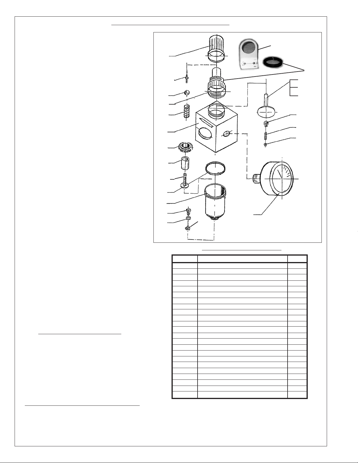
PARTS LIST / ASSEMBLY DIAGRAM
PART # DESCRIPTION QTY
1
2
3
4
5
6
7
8
9
10
11
12
13
14
15
16
17
18
19
20
21
22
23
Pressure Adjustment Knob
Sinistral Screw
Sinistral Nut
Pressure Adjustment Mounting
Spring
Body
Air Distributor
Filter Mesh
Filter Mesh Mounting
“O” Ring
Drain Cup
Adjustment Screw
Gasket
Water Valve Drain
Filter Valve Screw
Brass Gasket
Rubber Cover
Rubber Screw
Spring
Rubber Gasket
Pressure Gauge
Mounting Bracket
Retainer Ring
PLEASE READ THE FOLLOWING CAREFULLY
THE MANUFACTURER AND/OR DISTRIBUTOR HAS PROVIDED THE PARTS DIAGRAM IN THIS MANUAL AS A REFERENCE
THER THE MANUFACTURER NOR DISTRIBUTOR MAKES ANY REPRESENTATION OR WARRANTY OF ANY KIND TO THE BUYER THAT HE
OR SHE IS QUALIFIED TO MAKE ANY REPAIRS TO THE PRODUCT OR THAT HE OR
PRODUCT. IN FACT, THE MANUFACTURER AND/OR DISTRIBUTOR
SHOULD BE UNDERTAKEN BY CERTIFIED AND LICENSED TECHNICIANS AND NOT BY THE BUYER. THE BUYER ASSUMES ALL RISK AND
LIABILITY ARISING OUT OF HIS OR HER REPAIRS TO THE ORIGINAL PRODUCT OR REPLACEMENT PARTS THERETO, OR ARISING OUT
OF HIS OR HER INSTALLATION OF REPLACEMENT PARTS THERETO.
EXPRESSLY STATES THAT ALL REPAIRS AND PARTS REPLACEMENTS
SHE IS QUALIFIED TO REPLACE ANY PARTS OF THE
TOOL ONLY. NEI-
1
1
1
1
1
1
1
1
1
1
1
1
1
1
1
1
1
1
1
1
1
1
1
 Loading...