

Page 1
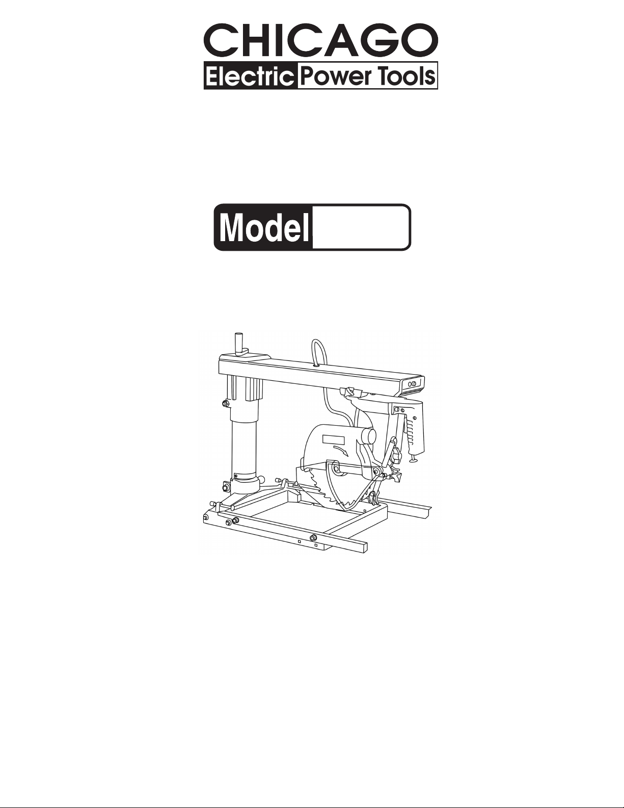
RADIAL ARM SAW
1
8-
/4 INCH
42933
ASSEMBLY AND OPERATING
INSTRUCTIONS
3491 Mission Oaks Blvd., Camarillo, CA 93011
Visit our Web site at http://www.harborfreight.com
Copyright© 2000 by Harbor Freight Tools®. All rights reserved. No portion of this
manual or any artwork contained herein may be reproduced in any shape or
form without the express written consent of Harbor Freight Tools.
For technical questions and replacement parts, please call 1-800-444-3353.
REV 11/04; 12/06
Page 2

Specifications
METINOITPIRCSED
stnemeriuqeRrewoP
rotoMekarbc
edalBwaS).aid(4/1-8
robrAhcni8/5
ecnatsiDtucssorC)mumixam(sehcni11
CpiR)mumixam(sehcni02
eziSelbaTsehcni4/3x8/5-72x61/1-51
ecnatsiDtu
stuCfohtpeDsehcni8/1-2:seerged09;sehcni2:seerged54
spotSxednIleveBseerged09,54,0
SxednIertiMseerged06dna,54,03,51,0:thgirdnatfeL
spot
seirosseccA40234#metI:tn
emecalpeRedalBwaS
esahpelgnis,zH06,CAV021
Save This Manual
sttaw0331;spmadaol9.6;spmaputrats9.02
irtcele,MPReldnips0024,PH4/3-1
You will need the manual for the safety warnings and precautions, assembly instructions,
operating and maintenance procedures, parts list and diagram. Keep your invoice with this
manual. Write the invoice number on the inside of the front cover. Keep the manual and
invoice in a safe and dry place for future reference.
Safety Warnings and Precautions
WARNING: When using tool, basic safety precautions should always be followed to
reduce the risk of personal injury and damage to equipment.
Read all instructions before using this tool!
1. Keep work area clean. Cluttered areas invite injuries.
2. Observe work area conditions. Do not use machines or power tools in damp or wet
locations. Don’t expose to rain. Keep work area well lighted. Do not use electrically
powered tools in the presence of flammable gases or liquids.
3. Keep children away. Children must never be allowed in the work area. Do not let
them handle machines, tools, or extension cords.
4. Store idle equipment. When not in use, tools must be stored in a dry location to
inhibit rust. Always lock up tools and keep out of reach of children.
5. Do not force tool. It will do the job better and more safely at the rate for which it was
intended. Do not use inappropriate attachments in an attempt to exceed the tool
capacity.
SKU 42933 For replacement parts, please call 1-800-444-3353. Page 2
Page 3

6. Use the right tool for the job. Do not attempt to force a small tool or attachment to
do the work of a larger industrial tool. There are certain applications for which this tool
was designed. Do not modify this tool and do not use this tool for a purpose for which
it was not intended.
7. Dress properly. Do not wear loose clothing or jewelry as they can be caught in
moving parts. Protective, electrically nonconductive clothes and nonskid footwear are
recommended when working. Wear restrictive hair covering to contain long hair.
8. Use eye and ear protection. Always wear ANSI approved impact safety goggles.
Wear a full face shield if you are producing metal filings or wood chips. Wear an ANSI
approved dust mask or respirator when working around metal, wood, and chemical
dusts and mists.
9. Do not overreach. Keep proper footing and balance at all times. Do not reach over or
across running machines.
10. Maintain tools with care. Keep tools sharp and clean for better and safer
performance. Follow instructions for lubricating and changing accessories. Inspect tool
cords periodically and, if damaged, have them repaired by an authorized technician.
The handles must be kept clean, dry, and free from oil and grease at all times.
11. Disconnect power. Unplug when not in use.
12. Remove adjusting keys and wrenches. Check that keys and adjusting wrenches
are removed from the tool or machine work surface before plugging it in.
13. Avoid unintentional starting. Be sure the switch is in the Off position and locked
when not in use, and before plugging in. Do not carry any tool with your finger on the
trigger, whether it is plugged in or not.
14. Stay alert. Watch what you are doing, use common sense. Do not operate any tool
when you are tired.
15. Take caution as some woods contain preservatives such as copper chromium
arsenate (CCA) which can be toxic. When cutting these materials extra care should
be taken to avoid inhalation and minimize skin contact.
16. Check for damaged parts. Before using any tool, any part that appears damaged
should be carefully checked to determine that it will operate properly and perform its
intended function. Check for alignment and binding of moving parts; any broken parts
or mounting fixtures; and any other condition that may affect proper operation. Any
part that is damaged should be properly repaired or replaced by a qualified technician.
Do not use the tool if any switch does not turn On and Off properly.
17. Guard against electric shock. Prevent body contact with grounded surfaces such as
pipes, radiators, ranges, and refrigerator enclosures.
18. Replacement parts and accessories. When servicing, use only identical
replacement parts. Use of any other parts will void the warranty. Only use accessories
intended for use with this tool. Approved accessories are available from Harbor Freight
Tools.
SKU 42933 For replacement parts, please call 1-800-444-3353. Page 3
Page 4

19. Do not operate tool if under the influence of alcohol or drugs. Read warning
labels on prescriptions to determine if your judgment or reflexes are impaired while
taking drugs. If there is any doubt, do not operate the tool.
20. Use proper size and type extension cord. If an extension cord is required, it must
be of the proper size and type to supply the correct current to the tool without heating
up. Otherwise, the extension cord could melt and catch fire, or cause electrical
damage to the tool. This tool requires use of an extension cord of 0 to 10 amps
capability (up to 50 feet), with wire size rated at 18 AWG. Longer extension cords
require larger size wire. If you are using the tool outdoors, use an extension cord rated
for outdoor use (signified by “WA” on the jacket).
21. Maintenance. For your safety, service and maintenance should be performed
regularly by a qualified technician.
Safety Precautions When Using Radial Saws
1. Disconnect the line cord from the electrical outlet before servicing the Radial Arm Saw.
2. After cutting, wait until the saw blade comes to a complete stop before removing stock
from the table, reaching around the saw blade, or leaving the area.
3. Never walk away and leave the saw running.
4. When making rip cuts, feed the stock into the blade against the direction of the blade
rotation.
5. Always use a push stick when ripping small or thin stock.
6. Keep saw blade sharp and free of all rust and pitch.
7. Always use the anti-kickback finger attachment when making rip cuts. Feed stock from
the opposite end from the anti-kickback finger attachment.
8. Always use the saw blade guides and fence, and never push stock being cut by hand.
9. Tighten and lock all adjusting (saw blade positioning) screws before operating.
10. Keeps hands out of the path of the saw blade during operation.
11. Only use 8-inch saw blades with 5/8 inch arbor on this machine.
12. Always secure the stock being cut with clamps whenever possible.
13. Make sure that the Switch is in the OFF position before plugging the line cord into the
electrical outlet.
14. Many saw accidents are caused by dull, badly set, and improperly filed cutting blades;
gum or resin adhering to the cutting blade; and by saw blade misalignment with the
fence. Such conditions can cause the stock to stick, jam, stall the saw blade, or kick
back at the operator. Never use carbide blades to cut anything other than wood;
cutting hard materials can cause the carbide blade to shatter and break apart.
SKU 42933 For replacement parts, please call 1-800-444-3353. Page 4
Page 5

WARNING: Never attempt to free a stalled saw blade without first turning OFF the
saw motor.
15. Provide proper support for the stock based on its size and the type of operation to be
performed.
16. Avoid awkward hand positions (i.e., crossing arms during operation) in which a
sudden slip could cause your hand to move into the moving saw blade.
17. Before making any adjustments to the Radial Arm Saw, the Switch should be in the
OFF position and the Switch locked OFF.
18. Never turn the Radial Arm Saw ON before clearing the table and work surface of all
objects (tools, scraps of wood, etc.), except the stock to be cut.
19. Always lock the carriage arm in place before lowering the saw blade. Otherwise, when
the saw blade touches the stock, it may draw itself backward (with you) into the cutting
area.
20. Never cut more than one piece of stock at a time, for any type of cut.
21. When cross cutting, always return the carriage arm to the rear position before letting
go of the Handle.
22. Avoid Kickback of stock:
- For rip cuts, the saw blade must be exactly parallel to the fence to prevent pinching or
heeling. Use a stock separator on the output side of the stock cut.
- Only feed the stock against the rotation of the saw blade.
- Keep the stock firmly on the table while cutting.
23. When making rip cuts:
- Push only on the main section of stock, between the saw blade and the fence.
- Always use a push stick, never your hands.
- Do not release the stock before the cut is complete, and push beyond the saw blade.
- Always push the stock through the saw blade, never pull it through from the opposite
direction.
- Always use the anti-kickback claws.
- Do not rip stock that is bowed, warped, or has nonparallel edges.
24. The use of abrasive, cut off, or wire wheels can be dangerous and is not
recommended.
Note: Performance of this tool may vary depending on variations in local line voltage. Extension cord usage may also affect tool performance.
Warning: The warnings, cautions, and instructions discussed in this instruction manual
cannot cover all possible conditions and situations that may occur. It must be understood by the operator that common sense and caution are factors which cannot be
built into this product, but must be supplied by the operator.
SKU 42933 For replacement parts, please call 1-800-444-3353. Page 5
Page 6
Unpacking
When unpacking, check to make sure that all the parts are included. Refer to the Parts List
and Assembly Drawing at the end of this manual. If any parts are missing or broken, please
call Harbor Freight Tools at the number on the cover of this manual as soon as possible.
Installation
During the assembly and installation procedure, you may have to refer to the Parts List and
Assembly Drawings located at the end of this manual.
1. Secure the Radial Arm Saw to a solid bench top (or table) by bolting (or clamping) the
saw frame down to the bench top.
- The workbench must not be able to slide or tip over. Affix to floor if necessary.
- Position the Radial Arm Saw (or saw and bench) to slope slightly to the rear so the
radial arm carriage will not roll forward due to gravity.
- The workbench should be of the appropriate length and width to allow the operator
to stand aside of the saw blade, whatever position the saw blade is in.
- The work area should have adequate, overhead, non-glare lighting.
- Always lock the radial arm carriage before moving the unit.
2. Turn the Base (152) assembly upside down. Attach Table
A (127) squarely to the Base assembly using the four
cross-head Tapping Screws (165).
3. Attach the table stabilizer Stands to both sides of the
Base using four Hex Nuts (82), Washers (149), and
Round Head Bolts (148).
4. Place the Table and Base assembly on the workbench,
right side up. Secure to the workbench with nuts, bolts,
and washers (not supplied).
5. Position Table B (126) and Table C (125), and the rip
fence (guide) and secure them by partially tightening the
two screw clamps built into the Base assembly.
6. Set the Arm (118) assembly column into the Column
Base. Move the Arm slightly to the left or right until the
column index knob locks into the arm support column.
The arm support column has nine positive stops: 0, 15,
30, 45, and 60 degrees (left and right).
7. Attach the Elevating Handle assembly to the Arm using
the Allen wrench (provided).
8. Attach the Saw Blade (17) to the Gear Shaft (19) and
secure with the Outside Flange (16) and Bolt (15).
REV 03/01
SKU 42933 For replacement parts, please call 1-800-444-3353. Page 6
Page 7

Lock the Gear Shaft with the Stopper Pin (22) located at
the front part of the Gear Case Cover (26).
Using a wrench, tighten the Bolt (15) over the Outside
Flange (16), counterclockwise.
9. Place the Safety Guard (10) over the Saw Blade and tighten
in place.
10. Install the anti-kickback pawl on the Safety Guard (10) with the
pawls facing the rear of the machine.
11. Set the height by loosening its lock knob and moving it up or
down. Retighten again when set to the proper height.
12. Verify that no play exists in the carriage, and that the arm, yoke,
and bevel locks and clamps are tight.
13. Slip the Dust Guide (4) over the exhaust stem located on the
Safety Guard.
Operating Controls
Elevating Handle (88)
Yoke Pivot Clamp Handle (88)
Safety Guard (10)
Arm Index Knob (115)
Screw Clamp (137)
ON / OFF Switch – The Switch has a built-in locking feature which
requires a key to be inserted before the saw can be turned ON.
Removing the Key and pushing the OFF button locks the saw
against unintended use. For crosscutting, press the green Switch
in, then squeeze and hold the Trigger. For rip cutting, press the
Switch (122) with Key (98)
Trigger
Bevel Index Knob (74)
Bevel Lock Knob (71)
Lock On Button
Safety Guard Lock Knob (5)
Anti-kickback Arm (13)
SKU 42933 For replacement parts, please call 1-800-444-3353. Page 7
Page 8

green Switch in, squeeze the Trigger (motor starts), then push up on the Lock On Button (
cutting only
again will release the Lock On Button, turning the motor off.
Carriage Lock – The Carriage Lock Knob located on the left side
of the Radial Arm, permits the saw assembly to be moved in or
out, and locked at the desired position on the arm. It must be fully
released for any crosscutting, and tightly locked for all operations
in which the saw assembly is stationary. To lock turn clockwise.
To unlock turn counterclockwise.
Arm Angle – The Arm Index Knob (142) and Washer (140) are
located at the Column Base (132). They can index, release, and
secure the arm angle for various miter positions. Positive index
stops are 0, 15, 30, 45, and 60 degrees (left and right). Non-index
stops can also be set within the range of the arm assembly.
Yoke Pivot- The Yoke Index Knob, located at the top of the Yoke
(under the Carriage Arm) indexes the Yoke horizontally to 0 degree
(crosscuts) or 90 degree (for rip cuts). Loosen the Yoke Pivot Clamp
Handle and pull out the Yoke Index Knob. Turn the motor assembly
until it locks at the index position. Lock the Yoke Pivot Clamp Handle.
) to keep the motor running without holding the Trigger in. Depressing the Trigger
for rip
Blade Angle – The Bevel Index Knob (74) and the Bevel Lock Knob
(71) are used to set the Blade angle (variable or indexed). Loosen the
Bevel Index Knob (71). Turn the motor assembly clockwise or counterclockwise to the index notch of 0, 45, or 90 degrees, or to a variable
position without using the index notch. Tighten the Bevel Lock Knob
by turning clockwise.
Depth of Cut – The Elevating Handle (100) at the rear of the arm
is used to raise and lower the height of the Saw Blade. Turn the
Elevating Handle clockwise to raise the Saw Blade or counterclockwise to lower it.
Adjustments
The following checks, and possible adjustments, should be done in the order listed before
beginning operation.
WARNING: For safety, unplug the line cord to the Radial Arm Saw.
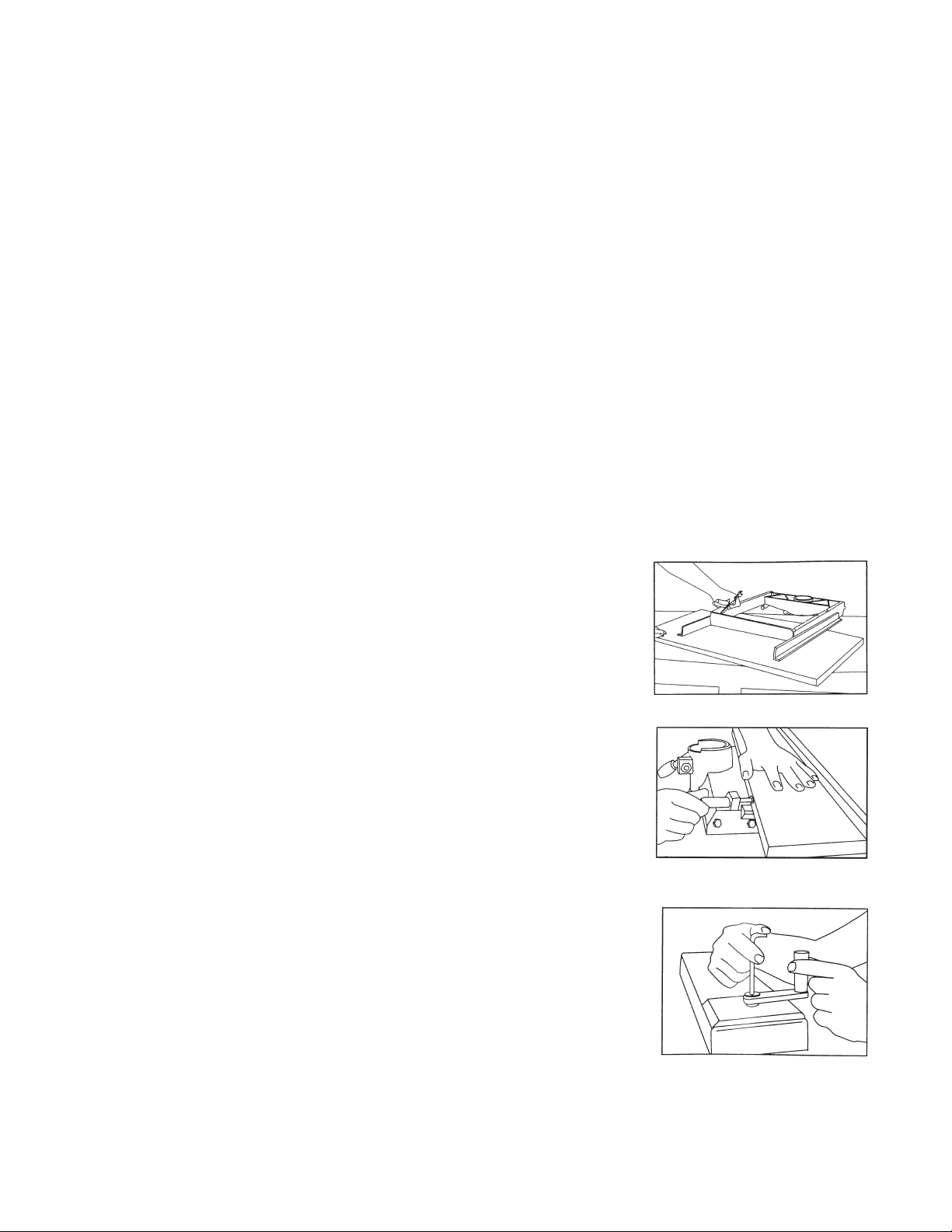
1. Tables A (127), B (126), and C (125) are checked for straightness at the factory.
SKU 42933 For replacement parts, please call 1-800-444-3353. Page 8
Page 9

However, changes in humidity can slightly alter the condition of the wood. With the
Screw Clamps (131) tightened, use a straight edge or framing square to check for
flatness and squareness. Sand down any high spots using fine sandpaper.
2. Check for Arm tightness on the Column (132). If loose, tighten Bolt (115).
3. Check the crosscut travel of the Saw Blade for squareness.
- Lock or tighten all adjustment levers and knobs.
- Lower the Arm until it just clears the Table A front.
- Place a framing square so it just touches a tooth of the Saw
Blade.
- Mark this location with a pencil on the table and draw a straight
line using the square.
- Check that the Saw blade follows this line from front to back.
If the Saw Blade moves to the right or left side of the line as it travels the entire length
of the Arm, loosen the Screw Clamps (137) and lightly tap on the Table left or right side
until there is full travel alignment. Tighten the Screw Clamps again.
4. Check that the Saw Blade is square to Table A.
- Place a framing square on Table A so that the square is flat
on the Saw Blade (not touching teeth).
- If there is no gap between the square and the Saw Blade, no
adjustment is necessary.
- If the square does not touch the Saw Blade evenly (with the
square flat on the Table A), loosen the Bevel Lock Knob (71) and
adjust the motor until the gap between Saw Blade and the square
is eliminated.
5. Check that the Saw Blade is square to the rip fence.
- Firmly place a framing square against the rip fence and the blade
as shown to the right. The square should not touch any teeth.
- If the square is not flush with the entire blade, loosen the yoke
pivot Clamp Handle (66) and move the motor assembly until any
gaps have been eliminated. Tighten the Yoke Pivot Clamp and
recheck alignment. (This will simultaneously set both yoke indexing
positions for in and out ripping.)
Preparing the Work Table A
In order to move the Saw Blade into different cutting positions, kerf marks (or grooves) must
be cut into the worktable. It is recommended to cut grooves into a piece of 1/4 inch plywood
mounted to the surface of Table A.
1. Cut a piece of 1/4 inch plywood the same size as Table A.
2. Mount the plywood to Table A using self-tapping, countersinking screws at the four
corners of Table A.
3. Set the Carriage Arm at 0 degrees and lock in place.
SKU 42933 For replacement parts, please call 1-800-444-3353. Page 9
Page 10

4. Set the Saw Blade angle to 0 degrees index position (perpendicular to the worktable).
5. Draw out the Saw Blade to mid-range on the Carriage Arm and lock in that position.
6. Turn the Elevating Handle to lower the Saw Blade so it just touches the plywood top.
7. Place your hand on the Handle Assembly (87) and press the green ON button with the
other hand. Squeeze the Trigger (86) to start the motor.
8. With the same hand that you turned ON the machine, loosen the Carriage Lock Knob
and slowly move the Saw Blade back, cutting the rip fence; and then move it all the
way forward, cutting a groove into the entire depth of the plywood.
9. With the machine still running, turn the Elevating Handle 1/4 turn, lowering the Saw
Blade a little more. Pull the Handle back and forth again to cut the plywood groove a
little deeper. Tighten the Carriage Lock Knob again.
10. With the machine still running, loosen the yoke Clamp Handle (66) and pull out the
Yoke Index Knob and turn the yoke clockwise until it locks into the 90 degree.
This cuts a swing line into the worktable for in-ripping.
11. Once the quarter turn (swing line cut) is complete, lock the yoke Clamp Handle. With
the Saw Blade still turning, push on the Handle until the Saw Blade reaches the rip
fence, cutting the rip trough in the center of the worktable.
12. Turn the machine OFF and return the Saw Blade to the crosscut position. Lock the
Carriage Lock Knob.
13. Turn the machine ON and rotate the Yoke counterclockwise to the out-rip position. This
cuts the swing line for out-ripping. Loosen the Carriage Lock Knob.
14. Lock the yoke Clamp Handle (66) and, with the Saw Blade revolving, push the Handle
back until the new groove matches the groove cut in step 11. Turn the machine OFF.
15. Return the Saw Blade to the crosscut position. Unlock the Carriage Lock Knob (74b)
and move the motor assembly to the rear position, behind the fence. Pull out the Bevel
Index Knob (74) and lock the Saw Blade at index position 60 degrees. Turn on
machine and pull the Handle forward. This will cut a kerf mark for bevel crosscuts. Turn
the machine OFF.
16. Lock the Carriage Lock Knob and start the motor. Pull the Carriage Arm Index Lock
Knob and move the Arm to the 45 degree right-hand miter position. This will cut a
groove for miter cuts. Turn the machine OFF.
SKU 42933 For replacement parts, please call 1-800-444-3353. Page 10
Page 11

Operation
WARNING: The Radial Arm Saw can be very dangerous and cause serious injuries if not
operated properly. Review all safety precautions before operating. Always keep hands
out of the path of the moving Saw Blade.
Cross Cutting
1. Secure the stock to be cut against the table and fence.
If the stock length is short, do not hold with your hand. Use
a clamp to hold in place.
2. Adjust the Anti-kickback Arm (13) so it just clears the stock.
3. Check that the Pivot Yoke Clamp Lock and Bevel Index
Knob are set to 0 degrees and are secure in place.
4. Adjust the Elevating Handle (100) so the Saw Blade (17)
height is only 1/8 inch into the worktable.
5. Push the Handle backward so that the Saw Blade is in behind the stock to be cut.
6. Press the green Switch (122). Squeeze the Handle Trigger and slowly pull the Handle
toward you, causing the Saw Blade to cut the stock.
7. When the cut is complete, release the Trigger and push the Handle all the way back.
8. Wait for the Saw Blade to stop turning before removing the stock.
Mitre Cross Cutting
1. Loosen the yoke Clamp Handle (66) and pull out the Yoke
Index Knob.
2. Turn the motor assembly to the left or right and lock the
Yoke Index Knob at 45 degrees.
3. Tighten the yoke Clamp Handle (66).
4. Push the Handle backward so that the Saw Blade is in
behind the stock to be cut.
5. Secure the stock to be cut against the table and fence.
If the stock length is short, do not hold with your hand. Use a clamp to hold in place.
6. Adjust the Anti-kickback Arm (13) so it just clears the stock.
7. Press the green Switch (122). Depress and hold the Trigger in. Slowly pull the Handle
toward you, causing the Saw Blade to cut the stock.
8. When the cut is complete, release the Trigger and push the Handle all the way back.
9. Wait for the Saw Blade to stop turning before removing the stock.
SKU 42933 For replacement parts, please call 1-800-444-3353. Page 11
Page 12

Bevel Cross Cutting
1. Loosen the Bevel Lock Knob (71) and pull out the Bevel Index
Knob (74).
2. Turn the motor assembly clockwise or counterclockwise,
selecting the desired angle (variable or indexed, i.e., 45
degrees).
3. Tighten the Bevel Lock Knob (71) and push in the Bevel Index Knob (74).
4. Push the Handle backward so that the Saw Blade is in behind the stock to be cut.
5. Secure the stock to be cut against the table and fence. If the stock length is short, do
not hold with your hand. Use a clamp to hold in place.
6. Adjust the Anti-kickback Arm (15) so it just clears the stock.
7. Press the green Switch (122). Squeeze the Trigger and push the Handle all the way
back.
8. When the cut is complete, release the Trigger and push the Handle all the way back.
Compound Cross Cutting
Compound crosscutting combines the mitre and bevel functions. Set the Saw Blade angles
as previously described. Continue to follow steps 4 through 9, above.
In-Rip Cutting
Ripping is the process of cutting stock along the grain (or lengthwise). The stock if fed into
the Saw Blade against the blade rotation (similar to a table saw). The fence is used as a
guide to help maintain cutting width.
1. Loosen the yoke Clamp Handle (66) and pull out the
Yoke Index Knob.
2. Turn the motor assembly to the left and lock the Yoke
Index Knob at 90 degrees.
3. Tighten the yoke Clamp Handle (66).
4. Adjust the Saw Blade Safety Guard (7) so it is just above
the surface of the stock to be ripped.
5. Adjust the Anti-kickback Arm (13) so it is just above the
stock surface.
6. Adjust the Carriage Arm so that the Saw Blade is at the desired depth for the rip cut,
and securely lock the Carriage Lock Knob in place.
Note that the larger portion of the stock being ripped should be between the Fence
and the Saw Blade.
7. Adjust the Elevating Handle (100) so that the Saw Blade is 1/16 inch into the worktable.
8. Verify that the Bevel Index Knob is locked into 0 degrees.
SKU 42933 For replacement parts, please call 1-800-444-3353. Page 12
Page 13

9. Slide the stock to be ripped into the cutting area and verify that it slides easily beneath
the Safety Guard, Anti-kickback Arm, and (optional) Spreader Plate, and there is no
wobble space. Remove stock from cutting area.
10. Press the green Switch (122), squeeze the handle Trigger (93) (motor starts), and push
up on the Lock On Button.
11. From the side of the machine, feed the stock into the Saw Blade (against its rotation)
using a (long) push stick.
WARNING: Never use your hand to push the stock through the Saw Blade. Never reach
around the Saw Blade while it is running. Serious injury can occur to hands and arms.
12. When the cut is complete, and before removing the stock, squeeze the Trigger or pull
down on the Lock On Button, and press the red Switch.
Out-Rip Cutting
Out-ripping is done when the in-rip position will not permit a wide enough cut. This function
moves the Saw Blade to the front of the machine. This operation is the same as in-rip cutting (previously described), with the exception that the Pivot Yoke is turned so that the
Handle is on the right side of the machine (opposite of the in-rip position).
1. Adjust the Saw Blade for In-rip cutting as described on page 12.
2. Loosen the Bevel Lock Knob (71) and pull out the Bevel Index Knob (74).
3. Turn the motor assembly clockwise or counterclockwise, selecting the desired angle
(variable or indexed, i.e., 45 degrees).
4. Tighten the Bevel Lock Knob (71) and push in the Bevel Index Knob (74).
5. Press the green Switch (122), squeeze the handle Trigger (motor starts), and push up
on the Lock On Button.
6. From the side of the machine, feed the stock into the Saw Blade (against its rotation)
using a (long) push stick.
WARNING: Never use your hand to push the stock through the Saw Blade. Never reach
around the Saw Blade while it is running. Serious injury can occur to hands and arms.
7. When the cut is complete, and before removing the stock, squeeze the Trigger or pull
down on the Lock On Button, and press the red Switch.
SKU 42933 For replacement parts, please call 1-800-444-3353. Page 13
Page 14

Maintenance
CAUTION: Before performing any maintenance, remove the Line Cord from the electrical outlet.
1. Yoke Tightness – Periodically check and tighten the yoke Clamp Handle (66).
Over time this handle may become loose and not tighten entirely. To correct this condition,
tighten the large Nut (64) at the base of the Handle using the 5/8 inch arbor wrench.
2. Cleaning – After each use, apply compressed air to blow clean all the parts of the Radial
Arm Saw.
3. Saw Blades – Never use a replacement blade rated lower than 5,000 RPM, and larger
than 8 inches diameter.
4. Motor Brushes – Inspect the two motor Brushes (55) after the first 50 hours of saw use.
After that, check every 10 hours. Replace if necessary by a qualified technician.
Improper Brush maintenance can cause motor failure. The Brush Caps (56) are located
on each side of the motor housing.
5. Lubrication – The Radial Arm Saw does not require initial lubrication. Periodically,
however, check all moving parts (i.e., knobs, levers, column shaft, Elevating Handle,
shafts) to make sure that they move smoothly. If lubrication is required, use a small amount
of light oil. Do not oil the Carriage Arm bearings because they are sealed and do not
require lubrication.
6. Motor Preventative Maintenance – In addition to worn motor Brushes, the following are
major causes of motor failure:
- Using a dull or sticking Saw Blade
- Feeding the stock through the Saw Blade too fast
- Starting the cut before the Saw Blade has reached full speed
- Abnormal friction caused by improper alignment of the motor assembly, especially when
ripping
- Low current or voltage supplied to the machine
- Buildup of dust in the motor housing, which prevents proper cooling.
SKU 42933 For replacement parts, please call 1-800-444-3353. Page 14
Page 15

Troubleshooting
MELBORPESUACNOITULOS
imrA
erauqsaekamtonlliwwaS
ertimeerged06doogarotucssorc
.tuc
etaruccatontuceerged06
klawotycnednetasaheceipkroW
rnehwecnefehtmorfyawa
gnippi
revoecnavdaotsdnetedalBwaS
tsafootkcotseht
tpedtuC
rehtoeht
tmra
skcar
edalB
gnittuc-ssorc
dalBwaS
rewop
otdneenomorfseiravh
niylhtoomslevarttonseodwaS
nehwspilseldnaHgnitavelE
waSehtgnirewolrognitavele
rotomdlohtonodsbonkgnipmalC
)s(noitisoptesehtotylbmessa
ton,eceipkrowserocsedalBwaS
tucdehsinifdoogagnivig
otd
netsedalbodadroedalBwaS
nehwedisenootkcotshsup
gnippirnehwsllatSe
rodeepsllufhcaertonlliwrotoM
edalBwaSlluD
waSehtgnilluptoN
stcartytriD
sgniraeBdaB
alBwaS
deeftoN
derised
edalBwaSlluD
esooltuNrobrA
edalBwaSlluD
noitacilppa
rotomdedaolrevO
mrah
tiwlellaraptonsielbaT
.thgiartstonsiecneFpiR
esoolsibonKkcoLleveB
mrahtiwlellaraptonsielbaT
onknodeppirtssdaerT)s(bonkecalpeR
)s(b
lludrotnebedalBwaS
ylreporpwasgni
gnileehsiedalBwaS
thgiartstonecnefpiR
ecnefotlellaraptonedalBwaS
hctiwSFFO/NOytluaF
tuo
denrubsgnidniwrotoM
ecnefpirehtotralucidnepreptons
nmulocdnamraehtneewtebyalphcumooT
egairracotdepmalcnehwesoolootekoY
ecnefpirdnakcotsneewtebtsuD
thgiartstonAelbatfoegderaeR
elbatkrowotralucidnepreptonedalBwaS
nmulocdnamraneewtebyalphcumooT
egairracotdepmalcnehwesoolootsiekoY
.ecnefehthtiwlellaraptonsiedalBwaS
.ecnefpirehtotralucidnepreptonsimrA
ylreporpedalB
nmulocdnamraehtneewtebyalphcumooTtlobeveelsnmulocnethgiT
eldnaHgnitavelEnoesoolwercSwercSnethgiT
edisenootgninaelsied
nmulocdnamraneewtebyalphcumooT
egairracotdepmalcnehwesoolootekoY
tuchsinifrofedalBwaSreporpmignisU
nmulocdnamraneewtebyalphcumooT
egairracotdepmalcnehwesoolootekoY
secnailpparehtohtiwdedaolrevotiucriC
sihtrofdetarrednusidesutiucriC
ttsujdA
tlobeveelsnmulocehtnethgiT
eldnahpmalcekoYtsujdA
elbatkrownaelC
AelbaTtsujdA
.ecnefpirecalpeR
Aelba
TecalperrodnaS
edalBwaStsujdA
elsnmulocnethgiT
AelbaTtsujdA
jdA
nethgiT
daesU
edalBwaStsu
llupydaetsdna
stcartnaelC
sgniraeBecalpeR
ecnefpirecalpeR
lBwaStsujdA
naicinhcet
rotomecalpeR
enihcamsihtrof
tlobeve
eldnaHpmalCekoYtsujdA
bonKkcoLleveBtsujdA
edalbneprahsroecalpeR
tlobeveelsnmulocnethgiT
ldnaHpmalCekoYtsujdA
e
edalBwaSecalpeR
llupydaetsdnawols
edalBwaSecalpeR
tlobeveelsnmulocnethgiT
eldnaHpmalCekoYtsujdA
edalBwaSneprahsroecalpeR
neprahsroecalpeR
de
kcehctinuhctiwSehtevaH
ecnefpirehthtiwlevarttucssorceh
ecnefpirhtiwlevarttucssorctsujdA
wolsahtiwkcotsssorcaedalBwaSwarD
ecnefpiroterauqsedalBwaStsujdA
ahtiwkcotsssorcaedalBwaSehtwarD
ecnefpirehtoterauqsedalBwaStsujdA
lellarapotecnefroeda
deifilauqayb
enihcamehtroftlucrictnereffidaesU
rewoptneiciffushtiwtlucrictnereffi
ylwolseromedalBwaSotnikcotsdeeF
ehtspirt,sllats,staehrevorotoM
sesufrosrekaerbtiucric
acgniloocreporpmI
ecruosrewoP
yticapacrewoptneiciffus
evissecxeybdesu
rotomehtdnuoranoitalumuccatsudwas
neporotuodenrubgnidniwrotoM
evahtonodsrekaerbtiucric
ahc
riadesserpmochtiwgnisuohrotomnaelC
icinhcetdeifilauqagnisurotomecalpeR
na
rosrekaerbtiucricezisreporpllatsnI
yticapaceromhtiwenootstiucricegn
SKU 42933 For replacement parts, please call 1-800-444-3353. Page 15
Page 16

Parts List
traPnoitpircseDyt'QtraPnoitpircseDyt'QtraPnoitpircseDyt'Q
1etalpemaN175tloBpotStliT1011wercSdeeF1
28×5MwercS285)2(gnirpSeru
35rehsaW195revoCeldnaH1211esaBmrA1
4ediuGtsuD10621×9.3tSwercSgnippaT231121rehsaW1
5bonKxednIekoY3165.6×9.2tSwerc
66MtuN9626revoCeldnaH151106×21MtloB1
7wercSgnipmalCdrauG13602×4niPgnirpS1611eceiPreffuB2
8drau
9lebaL1568×5MwercS1811revoCelbaC1
01drauGytefaS166eldnaHpmalC1911)5(gnirpSerusserP1
11etalPdrau
215rehsaWgnirpS186draoBlebaLelacS1121redniBelbaC1
31y'ssAmrAkcabkcik-itnA196csiDlaiD1221hcti
41tloBdutS10761×8.4tSwercSgnippaT6321esaChctiwS1
51)tfel(41×8MtloB117bonKkcoLleveB1421yeK1
61egnalFedistuO127)1(gnirpSeru
71edalBwaS137pilc-C1621BelbaT1
81egnalFedisnI1a47bonKkcoLleveB1721CelbaT1
91tfahSraeG1b47bonKkcoLegairraC1821tuNts
02)1(gnirpSerusserP157niPbonK1921pilc-C1
126gniRgniniateR167tfahSgniraeB403121×6niPgnirpS2
22niPreppotS17792006gnira
3222×4ByeK187tfahSreppotS1231liaRediuG1
4283×8.4tSwercSgnippaT29761rehsaWnihT233101×5MwercS1
5202×5MwercS108egairr
62revoCesaCraeG1188rehsaWgnirpS85314rehsaW2
728×4MwercS2288MtuN8631eguaG1
8240108gniraeB1386rehsaW5731pmalCwercS2
92rehs
03raeGtuptuO158tloBdaeH.xeH193121×5MwercS1
1302gniRgniniateR168elffaB
23014101KgniraeBeldeeN178AeldnaH114156×21MtloBkcoLmrA1
3307×5wercSdooW288)4(gnirpSerusserP1241bonKxedn
4321rehsaWnihT298elffaBssorC1341)3(gnirpSerusserP1
53tfahSelddiM109recapS1441pilc-C1
63316121KgniraeBeldeeN119)4(gnirpS
73raeGelddiM129nottuBnOkcoL1641pmalCelbaT2
8323×8.4tSwercSgnippaT439reggirT174141×8MtloB4
93revoCesaC
0420108gniraeB2596rehsaW29418MrehsaW4
14ediuGnaF1696rehsaWgnirpS2051dnatS2
24naF179BeldnaH11
34rotoR18921×6MwercS5251esaB1
44rotatS1996rehsaWgnirpS5351)tfeL(esaBdexiF1
54lioCelbaC5001eldnaHgnitavelE145
64pilCelbaC1101paCmrA156161x6MwercS4
745.9×5.3tSwercSgnippaT120121×4MwercS2661gnisuoH1
84revoCelbaC130141
9461×9.3tSwercSgnippaT240141rehsaW1
0501×4MwercS2501pmalCdroC1
15paCdnE1601eriWdaeL1
25tuNpirG1701)tfeL(l
35kcuhCtelloClacinoC1801mrA1
45redloHhsurB21-801wercSdaeHtalFknusretnuoC8
55hsurBnobraC22-801liaR2
65paChsurB2901)
GelbixelF146tuNtelloC171121MtuN2
G176draoBgnirpS2021retsloBdexiF1
aWreppotS148faeLgnirpSdexiF1831rehsaWgnipmalCnmuloC1
raeG14961×6MwercS284161×8MtloBdaeHdnuoR4
sserP1111elbaC1
SgnippaT2411)5(gnirpSerusserP2
wS1
sserP1521AelbaT1
oPediuG1
eB4131nmuloC1
aC1431recapS1
hctiwS104121rehsaW1
ImrA1
erusserP1541esaBnmuloC1
51)thgiR(esaBdexiF1
161×6MtloBdaeHdnuoR4
MtuNtelloC1761gnihsuB1
ebaLelacS1
thgiR(lebaLelacS1
SKU 42933 For replacement parts, please call 1-800-444-3353. Page 16
Page 17

Assembly Diagram (1-97)
NOTE: Some parts are listed and shown for illustration purposes only and are not available
individually as replacement parts.
SKU 42933 For replacement parts, please call 1-800-444-3353. Page 17
Page 18

Assembly Diagram
SKU 42933 For replacement parts, please call 1-800-444-3353. Page 18
Page 19

PLEASE READ THE FOLLOWING CAREFULLY
THE MANUFACTURER AND/OR DISTRIBUTOR HAS PROVIDED THE PARTS DIAGRAM IN THIS MANUAL
AS A REFERENCE TOOL ONLY. NEITHER THE MANUFACTURER NOR DISTRIBUTOR MAKES ANY
REPRESENTATION OR WARRANTY OF ANY KIND TO THE BUYER THAT HE OR SHE IS QUALIFIED TO
MAKE ANY REPAIRS TO THE PRODUCT OR THAT HE OR SHE IS QUALIFIED TO REPLACE ANY PARTS
OF THE PRODUCT. IN FACT, THE MANUFACTURER AND/OR DISTRIBUTOR EXPRESSLY STATES THAT
ALL REPAIRS AND PARTS REPLACEMENTS SHOULD BE UNDERTAKEN BY CERTIFIED AND LICENSED
TECHNICIANS AND NOT BY THE BUYER. THE BUYER ASSUMES ALL RISK AND LIABILITY ARISING
OUT OF HIS OR HER REPAIRS TO THE ORIGINAL PRODUCT OR REPLACEMENT PARTS THERETO,
OR ARISING OUT OF HIS OR HER INSTALLATION OF REPLACEMENT PARTS THERETO.
SKU 42933 For replacement parts, please call 1-800-444-3353. Page 19
 Loading...