

Page 1
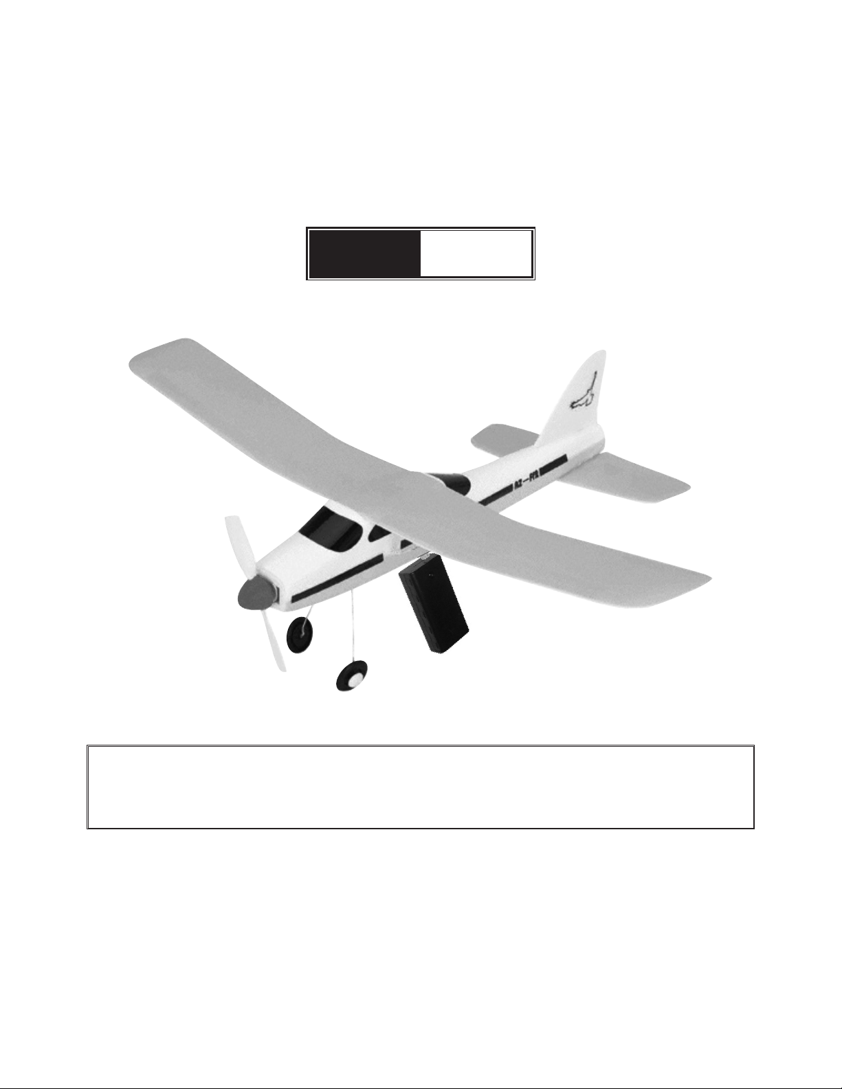
Lightning Airplane
with Charger
Model
42619
SET UP AND OPERATING INSTRUCTIONS
Visit our website at: http://www.harborfreight.com
IMPORTANT:
If damage is caused due to a crash, your warranty is void.
Copyright© 2000 by Harbor Freight Tools®. All rights reserved. No portion of this manual or any artwork
contained herein may be reproduced in any shape or form without the express written consent of
Harbor Freight Tools. Diagrams within this manual may not be drawn proportionally. Due to continuing
improvements, actual product may differ slightly from the product described herein. Tools required for
assembly and service may not be included.
For technical questions or replacement parts, please call 1-800-444-3353.
Manual Revised 10a
Page 2

SAVE THIS MANUAL
Use Precautions
Keep this manual for the safety warnings
and precautions, assembly, operating,
inspection, maintenance and cleaning
procedures. Write the product’s serial number
in the back of the manual near the assembly
diagram (or month and year of purchase if
product has no number). Keep this manual
and the receipt in a safe and dry place for
future reference.
SPECIFICATIONS
Main Body 10-5/8” L X 1” W
Main Wing 14-1/8” L X 2-3/8” W X 1/8” Thick
Small Wing 5-3/4” L X 1-3/4” W X 1/8” Thick
Flap 1-1/4” L X 1-3/4” W
Weight 1.2 lb.
Charge Time 30 seconds ONLY. Do not charge
more than 30 seconds
Charger Uses 2 AA size batteries
(not included)
Includes Propellers Spinner Set (2)
Portable Charger
Landing Gear
FOR AGES 9 AND OLDER
Do not operate the product if under the 1.
inuence of alcohol or drugs. Read
warning labels on prescriptions to
determine if your judgment/reexes
might be impaired.
Use as intended only.2.
Wear ANSI-approved impact safety 3.
goggles.
Inspect before every use; do not use if 4.
parts are loose or damaged.
Do not catch the Airplane while it is in 5.
motion.
Only use the Airplane in a large area free 6.
of trees, power lines and other obstacles.
Children using the Airplane or 7.
Charger should always be under adult
supervision.
Do not y near buildings, cars or busy 8.
streets.
Do not y near electrical wires.9.
IMPORTANT SAFETY
INFORMATION
Do not y the Airplane at or near other 10.
people or animals.
To not attempt to y the Airplane if wind 11.
Assembly Precautions
Assemble only according to these 1.
instructions. Improper assembly can
create hazards.
Wear ANSI-approved safety goggles 2.
during assembly.
Keep assembly area clean and well lit.3.
Keep bystanders out of the area during 4.
assembly.
conditions are above 10 MPH.
Battery Precautions
Position batteries in proper polarity and 1.
do not install batteries of different
types, charge levels, or capacities
together.
Do not install used and new batteries 2.
together.
Use only ‘AA’ batteries in the charger.3.
Do not assemble when tired or when 5.
under the inuence of drugs or
medication.
REV 09k, 09l
Page 2 For technical questions, please call 1-800-444-3353. SKU 42619
Page 3

ASSEMBLY
Read the ENTIRE IMPORTANT
SAFETY INFORMATION
section at the beginning of this
document including all text under
subheadings therein before set up
or use of this product.
Figure 3 - Landing Gear
Locate the Main Wing and Fuselage. 1.
Remove the tape covering on the center
of the Fuselage. Adhere the Wing to the
Fuselage making sure that the center of
the Wing lines up with the center of the
Fuselage. Use a small pin or apply slight
pressure to hold the wing in place until
the adhesive is tightly in place.
Wing
Support
Figure 1-Wing to Fuselage
2. Peel off the cover from the two small
pieces of adhesive tape on the underside
of both wings. Adhere the two Wing
Supports to the Wing-see Figure 1.
4. While squeezing the legs of the Landing
Gear together, insert legs into the slot
on the bottom of the Fuselage. After
the Landing Gear is inserted, release
pressure on the Landing Gear Legs so
that they snap into place and are held in
their slot on the Fuselage-see Figure 3.
Figure 4 - Propeller to Motor
5. Plug the Propeller Spinner set on the
Motor. Make certain that the Propeller
ts tightly on the Motor Shaft-see Figure
4.
Figure 2 -Stabilizer to Fuselage
3. Peel off the covering from the adhesive
tape located on the bottom side of the
Fuselage Tail. Making certain that the
mid point of the Stabilizer is lined up with
the midpoint of the Fuselage, attach the
Horizontal Stabilizer to the Fuselage-see
Figure 2.
REV 09k
CHARGING
If the temperature is lower than 55° F, 1.
warm the battery by holding it or bringing
it indoors to a warmer temperature
before charging. Do not heat the battery
with a ame.
If the battery is hot or warm from 2.
previous use, allow it to cool to room
temperature before charging.
Insert two ‘AA‘ batteries into the charger. 3.
CAUTION! Position batteries in proper
polarity and do not install batteries
of different types, charge levels, or
capacities together.
Page 3For technical questions, please call 1-800-444-3353.SKU 42619
Page 4

Turn the plane’s switch off. The 4.
OFF position is the position closer
to the Battery. Plug the Charger into
the Charging hole on the Fuselage.
Charging takes about 30 seconds. The
NiMH battery in the plane is fully charged
when it becomes warm to the touch.
Test the charge by touching the battery
with your nger.
To adjust the pattern, bend the rudder 5.
slightly left or right. If the head of the
plane appears too heavy, you can correct
this by slightly bending the Horizontal
Stabilizer upward or downward.
Turn the airplane’s switch off after use.6.
MAINTENANCE
WARNING! DO NOT CHARGE THE
BATTERY LONGER THAN 30
SECONDS. Allow the battery to
cool down after each charging.
Overcharging can cause overheating,
resulting in PERSONAL INJURY or
property damage.
OPERATION
Choose a day when the wind is light. 1.
Find a wide-open eld.
NOTE: Keep an eye on your Airplane to
avoid losing it. For this reason, a large
area free of obstructions and debris is
ideal for ying your Airplane.
Turn the Switch ON. Gently toss the 2.
Airplane into the wind with the Nose
pointing slightly upward. Keep the
Wings level. The Airplane will slowly
begin climbing.
The airplane will y in a circle, in a radius 3.
of about 24 to 30 Feet. If the ying
radius is too big or if the Airplane is ying
straight, you can adjust its pattern for the
next ight.
After being fully charged, the airplane will 4.
y for a period greater than one minute,
and will climb to about 50 feet altitude.
Let the battery cool down between ights 1.
to maximize performance.
Do not use polystyrene cement for 2.
repairs, as it may melt parts of the plane.
If the Propeller Shaft has been pushed 3.
into the Body after a collision, you can
simply pull the Shaft out. Make certain
that the power is OFF before you do so.
Let the battery run out before each 4.
charge to prolong battery life.
Remove batteries if the Airplane is not 5.
used for a long period of time.
PARTS LIST
Part Description
RZ - FF2 - 1 Wing & Stabilizer
RZ - FF2 - 2 Battery
RZ - FF2 - 3 Portable Charger
RZ - FF2 - 5 Propeller / Spinner
RZ - FF2 - 6 Landing Gear
RZ - FF2 - 7 Battery Base
RZ - FF2 - 8 Motor
RZ - FF2 - 9 Fuselage / Plane Body
Note: Some parts are listed and shown for
illustration purposes only, and are not
available individually as replacement
parts.
IMPORTANT:
If damage is caused due to a crash, your warranty is void.
REV 01c, 02a; 05c; 05j; 06e; 09a
Page 4 For technical questions, please call 1-800-444-3353. SKU 42619
 Loading...