

Page 1

Oscillating spindle sander
Model
38160
asseMbly and Operating instructiOns
Visit our website at: http://www.harborfreight.com
read this material before using this product.
Failure to do so can result in serious injury.
saVe this Manual.
Copyright© 1998 by Harbor Freight Tools®. All rights reserved. No portion of this manual or any artwork contained
herein may be reproduced in any shape or form without the express written consent of Harbor Freight Tools.
Diagrams within this manual may not be drawn proportionally. Due to continuing improvements, actual product may
differ slightly from the product described herein. Tools required for assembly and service may not be included.
For technical questions or replacement parts, please call 1-800-444-3353.
revised Manual 10c
Page 2

saVe this Manual
Keep this manual for the safety warnings
and precautions, assembly, operating,
inspection, maintenance and cleaning
procedures. Write the product’s serial number
in the back of the manual near the assembly
diagram (or month and year of purchase if
product has no number). Keep this manual
and the receipt in a safe and dry place for
future reference.
iMpOrtant saFety
inFOrMatiOn
in this manual, on the labeling, and
all other information provided with
this product:
this is the safety alert
symbol. it is used to alert
you to potential personal
injury hazards. Obey all
safety messages that follow
this symbol to avoid possible
injury or death.
danger indicates a
hazardous situation
which, if not avoided, will result
in death or serious injury.
Warning indicates a
hazardous situation
which, if not avoided, could
result in death or serious injury.
nOtice is used to
address practices not
related to personal injury.
cautiOn, without the
safety alert symbol, is
used to address practices not
related to personal injury.
general tool safety Warnings
Warning read all safety warnings
and instructions. Failure to follow the
warnings and instructions may result
in electric shock, re and/or serious
injury.
save all warnings and instructions
for future reference.
KEEP GUARDS IN PLACE and in 1.
working order.
REMOVE ADJUSTING KEYS AND 2.
WRENCHES. Form habit of checking to
see that keys and adjusting wrenches
are removed from tool before turning it
on.
KEEP WORK AREA CLEAN. Cluttered 3.
areas and benches invite accidents.
DON’T USE IN DANGEROUS 4.
ENVIRONMENT. Don’t use power tools
in damp or wet locations, or expose them
to rain. Keep work area well lighted.
KEEP CHILDREN AWAY. All visitors 5.
should be kept safe distance from work
area.
cautiOn, used with
the safety alert
symbol, indicates a hazardous
situation which, if not avoided,
could result in minor or moderate
injury.
Page 2 For technical questions, please call 1-800-444-3353. SKU 38160
MAKE WORKSHOP KID PROOF 6.
with padlocks, master switches, or by
removing starter keys.
DON’T FORCE TOOL. It will do the job 7.
better and safer at the rate for which it
was designed.
reV 10e
Page 3

USE RIGHT TOOL. Don’t force tool or 8.
attachment to do a job for which it was
not designed.
recOMMended MiniMuM Wire
gauge FOr eXtensiOn cOrds
(120 VOlt)
naMeplate
aMperes
(at full load)
0 – 6 18 16 16 14
6.1 – 10 18 16 14 12
10.1 – 12 16 16 14 12
12.1 – 16 14 12
eXtensiOn cOrd
length
25’ 50’ 100’ 150’
do not use.
table a
13.
DON’T OVERREACH. Keep proper
footing and balance at all times.
14.
MAINTAIN TOOLS WITH CARE. Keep
tools sharp and clean for best and safest
performance. Follow instructions for
lubricating and changing accessories.
DISCONNECT TOOLS before servicing;
15.
when changing accessories, such as
blades, bits, cutters, and the like.
REDUCE THE RISK OF 16.
UNINTENTIONAL STARTING. Make
sure switch is in off position before
plugging in.
USE PROPER EXTENSION CORD. 9.
Make sure your extension cord is in good
condition. When using an extension
cord, be sure to use one heavy enough
to carry the current your product will
draw. An undersized cord will cause a
drop in line voltage resulting in loss of
power and overheating. Table A shows
the correct size to use depending on
cord length and nameplate ampere
rating. If in doubt, use the next heavier
gauge. The smaller the gauge number,
the heavier the cord.
WEAR PROPER APPAREL. Do not wear 10.
loose clothing, gloves, neckties, rings,
bracelets, or other jewelry which may get
caught in moving parts. Nonslip footwear
is recommended. Wear protective hair
covering to contain long hair.
ALWAYS USE SAFETY GLASSES. Also 11.
use face or dust mask if cutting operation
is dusty. Everyday eyeglasses only have
impact resistant lenses, they are NOT
safety glasses.
SECURE WORK. Use clamps or a vise 12.
to hold work when practical. It’s safer
than using your hand and it frees both
hands to operate tool.
reV 10e
USE RECOMMENDED ACCESSORIES. 17.
Consult the owner’s manual for
recommended accessories. The use of
improper accessories may cause risk of
injury to persons.
NEVER STAND ON TOOL. Serious 18.
injury could occur if the tool is tipped
or if the cutting tool is unintentionally
contacted.
CHECK DAMAGED PARTS. Before 19.
further use of the tool, a guard or other
part that is damaged should be carefully
checked to determine that it will operate
properly and perform its intended
function – check for alignment of moving
parts, binding of moving parts, breakage
of parts, mounting, and any other
conditions that may affect its operation.
A guard or other part that is damaged
should be properly repaired or replaced.
DIRECTION OF FEED. Feed work into 20.
a blade or cutter against the direction of
rotation of the blade or cutter only.
NEVER LEAVE TOOL RUNNING
21.
UNATTENDED. TURN POWER OFF.
Don’t leave tool until it comes to a
complete stop.
Page 3For technical questions, please call 1-800-444-3353.SKU 38160
Page 4
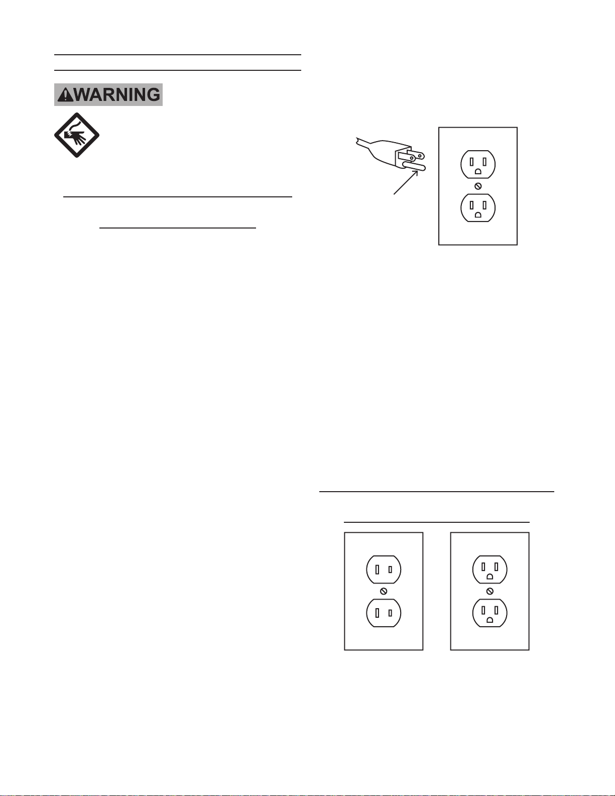
grOunding instructiOns
tO preVent
electric shOck
and death FrOM incOrrect
grOunding Wire
cOnnectiOn
read and FOllOW these
instructiOns:
3-pole receptacles that accept the tool’s
plug.
6.
Repair or replace damaged or worn cord
immediately.
110-120 V~ grounded tools: tools
with three prong plugs
In the event of a malfunction or 1.
breakdown, grounding provides a path
of least resistance for electric current
to reduce the risk of electric shock.
This tool is equipped with an electric
cord having an equipment-grounding
conductor and a grounding plug. The
plug must be plugged into a matching
outlet that is properly installed and
grounded in accordance with all local
codes and ordinances.
Do not modify the plug provided – if it will 2.
not t the outlet, have the proper outlet
installed by a qualied electrician.
Improper connection of the equipment-3.
grounding conductor can result in a risk
of electric shock. The conductor with
insulation having an outer surface that
is green with or without yellow stripes is
the equipment-grounding conductor. If
repair or replacement of the electric cord
or plug is necessary, do not connect the
equipment-grounding conductor to a live
terminal.
grounding
pin
125 V~ 3-prong plug and Outlet
(for up to 125 V~ and up to 15 a)
This tool is intended for use on a circuit 7.
that has an outlet that looks like the one
illustrated above in 125 V~ 3-prong
plug and Outlet. The tool has a
grounding plug that looks like the plug
illustrated above in 125 V~ 3-prong
plug and Outlet.
The outlet must be properly installed and 8.
grounded in accordance with all codes
and ordinances.
Do not use an adapter to connect this 9.
tool to a different outlet.
110-120 V~ double insulated tools:
tools with two prong plugs
Check with a qualied electrician or 4.
service personnel if the grounding
instructions are not completely
understood, or if in doubt as to whether
the tool is properly grounded.
Use only 3-wire extension cords that 5.
have 3-prong grounding plugs and
Page 4 For technical questions, please call 1-800-444-3353. SKU 38160
Outlets for 2-prong plug
To reduce the risk of electric shock, 1.
double insulated equipment has a
polarized plug (one blade is wider than
reV 10e
Page 5

the other). This plug will t in a polarized
outlet only one way. If the plug does not
t fully in the outlet, reverse the plug.
If it still does not t, contact a qualied
electrician to install the proper outlet. Do
not change the plug in any way.
Double insulated tools may be used in 2.
either of the 120 volt outlets shown in the
preceding illustration. (see Outlets for
2-prong plug.)
sander safety Warnings
For your Own safety read instruction
Manual before Operating sander
Wear eye protection.1.
Only use safety equipment that has been 8.
approved by an appropriate standards
agency. Unapproved safety equipment
may not provide adequate protection.
Eye protection must be ANSI-approved
and breathing protection must be
NIOSH-approved for the specic hazards
in the work area.
9.
Stay alert, watch what you are doing
and use common sense when operating
a power tool. Do not use a power tool
while you are tired or under the inuence
of drugs, alcohol or medication. A
moment of inattention while operating
power tools may result in serious
personal injury.
Support workpiece with miter gauge, 2.
backstop, or worktable.
The backstop is a fence near the surface 3.
that helps the operator maintain control
of the workpiece and prevents the
workpiece from being pulled into the
machine. For safety, it must be adjusted
very close to the sanding surface.
The worktable is the surface mounted 4.
close to the sanding surface that the
operator rests the workpiece against
to prevent it from being pulled by the
sanding surface. For safety, it must
be adjusted very close to the sanding
surface.
dO nOt Operate With any 5.
guard disabled, daMaged, Or
reMOVed. Moving guards must
move freely and close instantly.
The use of accessories or attachments 6.
not recommended by the manufacturer
may result in a risk of injury to persons.
When servicing use only identical 7.
replacement parts.
Industrial applications must follow OSHA 10.
guidelines.
Maintain labels and nameplates on 11.
the tool. These carry important safety
information. If unreadable or missing,
contact Harbor Freight Tools for a
replacement.
Avoid unintentional starting. Prepare to 12.
begin work before turning on the tool.
People with pacemakers should 13.
consult their physician(s) before use.
Electromagnetic elds in close proximity
to heart pacemaker could cause
pacemaker interference or pacemaker
failure.
WARNING: Some dust created by power 14.
sanding, sawing, grinding, drilling, and
other construction activities, contains
chemicals known [to the State of
California] to cause cancer, birth defects
or other reproductive harm. Some
examples of these chemicals are:
• Lead from lead-based paints
• Crystalline silica from bricks and
cement or other masonry products
• Arsenic and chromium from chemically
reV 10e
Page 5For technical questions, please call 1-800-444-3353.SKU 38160
Page 6

treated lumber
Your risk from these exposures varies,
depending on how often you do this type
of work. To reduce your exposure to
these chemicals: work in a well ventilated
area, and work with approved safety
equipment, such as those dust masks
that are specially designed to lter out
microscopic particles. (California Health
& Safety Code § 25249.5, et seq.)
WARNING: Handling the cord on this 15.
product will expose you to lead, a
chemical known to the State of California
to cause cancer, and birth defects or
other reproductive harm. Wash hands
after handling. (California Health &
Safety Code § 25249.5, et seq.)
16.
The warnings, precautions, and
instructions discussed in this instruction
manual cannot cover all possible
conditions and situations that may occur.
It must be understood by the operator
that common sense and caution are
factors which cannot be built into this
product, but must be supplied by the
operator.
unpacking
When unpacking, make sure that the
item is intact and undamaged. If any parts
are missing or broken, please call Harbor
Freight Tools at 1-800-444-3353 as soon as
possible.
saVe these
instructiOns.
speciFicatiOns
Electrical Input 120 V~ / 60 Hz / 11 A
Motor No Load Speed 1787 RPM
Oscillations per
Minute
Oscillation Travel 7/8”
Sanding Belt Capacity 3/4” - 2”
Sanding Belt Height 4-1/2”
Sanding Thickness 3/16 - 11/16”
Dust Collection Port 2”
Table Tilt Angle 0 - 45°
Page 6 For technical questions, please call 1-800-444-3353. SKU 38160
58 OPM
rev 00c; 10c
Page 7

to change/install sand belts
(see parts diagram and parts list on pages 8 and 9)
place switch in “OFF” position, and unplug the sander before performing any of the steps below.
The Oscillating Sander has been shipped completely assembled with a 2” sand belt (#49) and regular core board
installed. Change sand belts as follows:
tO reMOVe sand belt
1. Grasp and hold sand belt (#49) on rotating axle (#46). Loosen nut (#51). If nut is too tight and rotating axle
spins inside sand belt, secure the rotating axle with a wrench and loosen nut.
2. Remove nut, big washer (#50), and sand belt. Unscrew rotating axle clockwise and remove core board (#36) also see instructions below describing how to remove core board.
3. Remove big washer (#50) and clean sawdust accumulation.
tO install sand belt
1. Replace big washer (#50). Fin side of washer should always be installed down. The ns help push sawdust
through the dust exhaust port opening, preventing buildup of sawdust. Sawdust buildup in this area may cause
the oscillating motion to stop. The big washer must be used with all sanding sleeves.
2. Select and install the desired rotating axle.
3. Install appropriate sand belt on the rotating axle. (Note: If sanding sleeve becomes difcult to install or remove,
apply talcum powder on the inside of the sand belt before installing on axle).
4. Install big washer (#50) and nut.
5. Grasp and hold sand belt and tighten nut. Do not overtighten.
replacing core boards
The Oscillating Sander comes with two core boards. The core board with the circular opening is for sanding when the working
table (#34) is level. The core board with the oblong opening is to be used when the working table is set at an angle.
to remove core boards
Push rmly from underneath the working table until core board is removed.
to insert core boards
1. Align the notch in the core board with the spring dowel (#35) located on the inner rim of the core board insert area.
2. Push down rmly until the core board is fully inserted and ush with the surface of the working table.
Page 7For technical questions, please call 1-800-444-3353.SKU 38160
Page 8

preparing For Operation
note:
√ this sander is designed for use on plastic and wood surfaces only. do not use this sander for sanding
metals. sanding metals will cause sparks that will ignite wood and dust particles on sander, in the dust
collector, or in workshop.
√ it is recommended that this tool not be used for extended work on any berglass or abrasive materials.
it has been found that those materials are subject to accelerated wear and possible premature failure,
as the berglass chips and grindings are highly abrasive to bearings, brushes, commutator, etc. During
any sanding of these materials, it is important the tool be cleaned frequently by blowing with an air
jet.
√ do not use sander without a sand belt. doing so will damage the rotating axle.
√ Make sure nut on the top of the rotating axle is tightened securely - but not overtightened.
sand belt selectiOn
Selecting the correct size diameter, type of grit and sanding sleeve is an extremely important step in achieving a
high quality nish:
√ Aluminum oxide, silicon carbide, and other synthetic abrasives are best for power sanding.
√ Natural abrasives, such as int and garnet are too soft for use in power sanding.
Select and install the desired sand belt for the particular application. Sand belts from 3/4”- 2” can be used with this
sander. Choose one that is close in size to the material you are sanding.
grit selectiOn
The condition of the surface to be sanded will determine which grit will do the proper job. In general, coarse grit will
remove the most material. Finer grit will produce the best nish in all sanding operations. If the surface is rough,
start with a coarse grit and sand until the surface is uniform. Medium grit may then be used to remove scratches
left by the coarser grit and ner grit used for nishing of the surface. Always continue sanding with each grit until
the surface is uniform.
Warning! Do not use water with this sander. It is for dry
sanding only. Wet sanding will damage the machine,
and may present a shock hazard. Use only in dry
locations.
reV 10c
Page 8 For technical questions, please call 1-800-444-3353. SKU 38160
Page 9

Operation
Exercise caution! Never force the material into the sander. You will become familiar with the sander’s features from
practice and use. If possible, practice sanding with a scrap piece of wood.
adJusting table angle
1. If working table is to be used at an angle, make sure to install the angle core board (with the oblong-shaped
opening) before sanding.
2. Loosen dial knob (#32) and adjust working table to the desired angle using the numbers on the rotating plate
(#31) as a guide.
3. Tighten dial knob securely so that the working table will not move during operation.
sanding
1. Turn sander on.
2. Let the motor build to its full speed, then gradually feed material against sanding sleeve. Do not let the material
contact sanding sleeve before turning on sander and allowing it to develop full speed.
Feed directiOn
When sanding, the sanding sleeve rotates counterclockwise. Therefore, feed the material against the sanding
sleeve from right to left. When fed from right to left, the rotation of the sanding sleeve sands against the material.
If fed in the opposite direction, the rotation forces of the spinning sanding sleeve will tend to throw or bounce the
material away from the sanding sleeve. This could cause loss of control of the material.
dust cOllectiOn capability
A standard 2-1/4” dust collect cover (#40) has been provided to make dustless sanding possible. The dust collection
port is located under the working top on the rear side of the sander. The pickup adapter end of a vacuum hose (not
included) will t inside the dust collect cover.
Even with a dust collection system, it is necessary to periodically clean sanding dust from the core board and big
washer areas. Sanding dust buildup in this area may cause the core board surface to rise above the working table
surface.
Maintenance
cleaning: Regularly clean the work surface with dry brush or clean cloth. Clean sawdust accumulations from core
board, big washers and rotating axle after each use.
lubricatiOn: No lubrication is required. All of the bearings in this tool are lubricated with a sufcient amount of
high grade lubricant for the life of the machine under normal operating conditions.
pOWer cOrd: Inspect the power cord periodically, and if damaged, have it repaired by an authorized technician.
replaceMent parts: When servicing, use only identical replacement parts. Use of any other parts will void the
warranty.
Page 9For technical questions, please call 1-800-444-3353.SKU 38160
Page 10

parts list
no. name Quantity no. name Quantity
1 stand 1 29 hexagon-headed bolt M8x20 6
2 switch 1 30 stand 1 of working table 1
3 Vertical Motor 1 31 rotating plate 1
4 key of Motor 1 32 parts of dial knob 2
5 clamp nail 2 33 crossed disc nail M5 x 8 7
6 Worm 1 34 Working table 1
7 spring ring for hole 55 1 35 spring dowel 3 x 8 1
8 bearing 80106 1 36 core board 2
9 spring ring for axle 32 1 37 hexagonn socket head cap
10 cross head disc nail M5 x 55 2 screw M6 x 20 2
11 screw Washer 5 holee 55 11 38 dust cover 1
12 rocker arm 2 39 hexagon-headed bolt M8 x 25 7
13 nut M5 4 40 dust collect cover 1
14 hexagon socket head cap 41 pointer 1
screw M4 x 30 2 42 stand ii of Working table 1
15 left core axle of Worm Wheel 1 43 stand board 1
16 Worm Wheel 1 44 dial 1
17 stand of Worm Wheel 1 45 key 5 x 50 1
18 screw M8 x 65 1 46 rotating axle of sand belt 1
19 right core axle of Worm Wheel 1 47 big Washer i 1
20 guide pole 1 48 rubber cylinder 1
21 shuttle axle cover 1 49 sand belt 1
22 shuttle axle 1 50 big Washer ii 1
23 spring dowel 4 x 30 1 51 left nut M8 1
24 bearing 61804 1 52 board of switch 1
25 hexagon socket head cap 53 nut M8 4
screw Mg x 16 5 54 Washer nut M8 4
26 spring Washer 8 7 55 rubber Washer 4
27 Frame to Fix Motor 1
28 screw Washer 14
Page 10 For technical questions, please call 1-800-444-3353. SKU 38160
Page 11

assembly diagram
Page 11For technical questions, please call 1-800-444-3353.SKU 38160
Page 12

liMited 1 year / 90 day Warranty
Harbor Freight Tools Co. makes every effort to assure that its products meet high quality
and durability standards, and warrants to the original purchaser that for a period of ninety
days from date of purchase that the engine/motor, the belts (if so equipped), and the blades
(if so equipped) are free of defects in materials and workmanship. Harbor Freight Tools also
warrants to the original purchaser, for a period of one year from date of purchase, that all other
parts and components of the product are free from defects in materials and workmanship (90
days if used by a professional contractor or if used as rental equipment). This warranty does
not apply to damage due directly or indirectly, to misuse, abuse, negligence or accidents,
repairs or alterations outside our facilities, normal wear and tear, or to lack of maintenance.
We shall in no event be liable for death, injuries to persons or property, or for incidental,
contingent, special or consequential damages arising from the use of our product. Some states
do not allow the exclusion or limitation of incidental or consequential damages, so the above
limitation of exclusion may not apply to you.
ALL OTHER WARRANTIES, EXPRESS OR IMPLIED, INCLUDING THE WARRANTIES OF
MERCHANTABILITY AND FITNESS.
To take advantage of this warranty, the product or part must be returned to us with
transportation charges prepaid. Proof of purchase date and an explanation of the complaint
must accompany the merchandise. If our inspection veries the defect, we will either repair or
replace the product at our election or we may elect to refund the purchase price if we cannot
readily and quickly provide you with a replacement. We will return repaired products at our
expense, but if we determine there is no defect, or that the defect resulted from causes not
within the scope of our warranty, then you must bear the cost of returning the product.
THIS WARRANTY IS EXPRESSLY IN LIEU OF
This warranty gives you specic legal rights and you may also have other rights which
vary from state to state.
3491 Mission Oaks Blvd. • PO Box 6009 • Camarillo, CA 93011 • (800) 444-3353
reV 10c
Page 12 For technical questions, please call 1-800-444-3353. SKU 38160
 Loading...