

Page 1
5-SPEED DRILL PRESS
Model
38119
SET UP AND OPERATING INSTRUCTIONS
Copyright© 1998 by Harbor Freight Tools®. All rights reserved. No portion of this manual or any artwork
contained herein may be reproduced in any shape or form without the express written consent of Harbor
Freight Tools. Diagrams within this manual may not be drawn proportionally. Due to continuing improvements,
actual product may differ slightly from the product described herein.
Distributed exclusively by Harbor Freight Tools®.
3491 Mission Oaks Blvd., Camarillo, CA 93011
Visit our website at: http://www.harborfreight.com
Read this material before using this product.
Failure to do so can result in serious injury.
SAVE THIS MANUAL.
For technical questions or replacement parts, please call 1-800-444-3353.
Revised 08a
Page 2

THANK YOU for choosing a Harbor Freight Tools product! For future reference, please complete
the owner’s record below:
Model: _________________ Serial No: __________________________ Purchase Date: ______________
SAVE THE RECEIPT, WARRANTY CARD AND THESE INSTRUCTIONS. It is important that you read the
entire manual to become familiar with the unit BEFORE you begin assembly.
TECHNICAL SPECIFICATIONS
Power Source: 1/3 HP, 120 V~, 60 Hz, Single Phase
Speeds: 620, 1100, 1720, 2340, 3100 RPM
Drill Chuck Capacity: 1/2”
Maximum Spindle Stroke: 2”
Maximum Distance from Chuck to Table: 6-3/4”
Maximum Distance from Chuck to Base: 10”
Maximum Swing: 9-1/2”
Column Diameter: 1.89”
Table Size: 6-5/16” x 6-1/2”
Overall Dimensions: 23” x 7” x 17”
Base Size: 7” x 11-1/8”
Rev 99f, 07b
Page 2SKU 38119 For technical questions, please call 1-800-444-3353.
Page 3
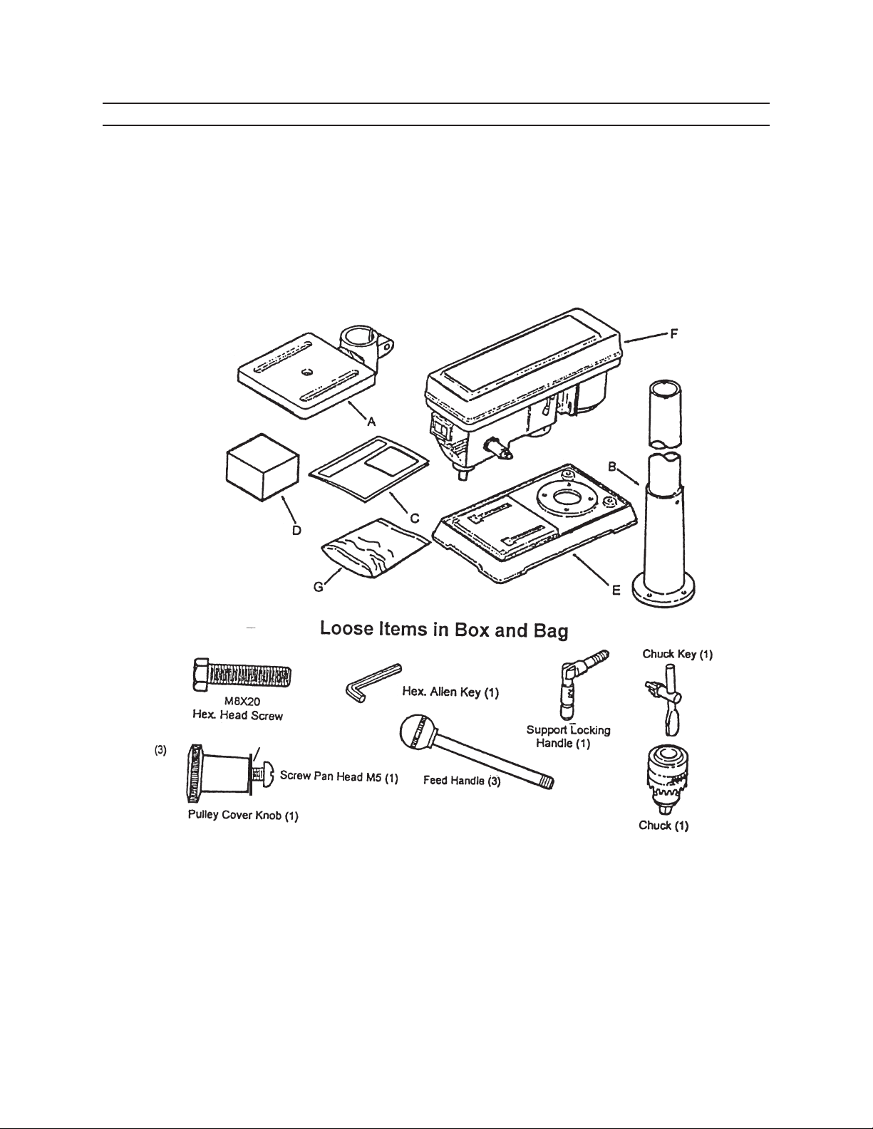
UNPACKING
Unpack and check contents. Make sure you have all parts described in the Parts Lists and Figure 1 on page 3.
Remove all preservative lubricants from parts with a clean dry cloth.
Some of the parts are heavy and may require two people for lifting.
If any parts are missing or broken, please call Harbor Freight Tools at 1-800-444-3353. The shipping box should contain:
A. Table Assembly B. Column Assembly
C. Instruction manual and warranty card D. Base
E. Head assembly F. Head Assembly
G. One (1) bag of loose items
5 MM I.D. x 11 MM O.D.
Flat Washer
4 MM
Figure 1
REV 01b
Page 3SKU 38119 For technical questions, please call 1-800-444-3353.
Page 4
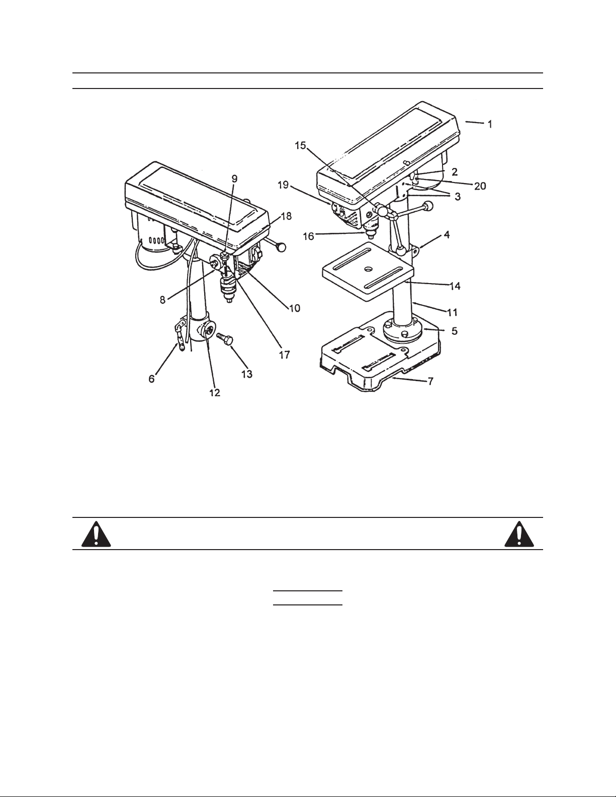
KNOW YOUR DRILL PRESS
1. Pulley Cover 10. Depth Scale
2. Belt Tension Locking Screw 11. Column
3. Head Lock Set Screws 12. Bevel Scale
4. Table Support 13. Table Lock Set Screw
5. Column Support 14. Table
6. Table Support Locking Handle 15. Feed Handles
7. Base 16. Chuck
8. Quill Spring Assembly 17. Feed Stop Rod
9. Pointer 18. Stop Nuts
19. Switch 20. Motor Stop
IMPORTANT SAFETY INSTRUCTIONS!
Read all instRuctions befoRe using this pRoduct!
Work Area
To a v o i d r i s k o f p e r s o n a l i n j u r y , e q u i p m e n T d a m a g e , f i r e a n d s h o c k , m a k e s u r e y o u r Work area is :
Free of damp, wet or rainy conditions1.
Free of ammable gasses or liquids2.
Childproof - use padlocks, master switches and remove starter keys when not in use.3.
Well-lit and well-ventilated4.
Page 4SKU 38119 For technical questions, please call 1-800-444-3353.
Page 5

Clean and uncluttered5.
The Operator
common sense a n d cauTion a r e f a c T o r s W h i c h c a n n o T b e b u i l T i n T o a n y p r o d u c T . Th e s e f a c T o r s m u s T b e
s u p p l i e d b y T h e o p e r a T o r . pl e a s e r e m e m b e r :
Prevent body contact with grounded surfaces such as pipes or radiators.1.
Stay alert. Never operate equipment if you are tired.2.
Do not operate the product if under the inuence of alcohol or drugs. Read warning labels on pre-3.
scriptions to determine if your judgment/reexes might be impaired.
Do not wear loose clothing or jewelry as they can be caught in moving parts.4.
Non-skid footwear is recommended.5.
Wear restrictive hair covering to contain long hair.6.
Use eye and ear protection. Always wear:7.
ANSI-approved dust mask or respirator when working around metal, wood, and chemical dusts a.
and mists.
A full face shield if you are producing metal or wood lings.b.
Ear protectorsc.
Maintain proper footing and balance at all times.8.
Do not reach over or across running machines.9.
Always check that adjusting keys and wrenches are removed from the tool or machine work surface 10.
before plugging it in.
Before Operating
Know the machine. Learn its applications and limitations, as well as the specic potential hazards.1.
Check for damage. If part of the machine is damaged, it should be carefully inspected to ensure 2.
that it can perform its intended function correctly. If in doubt, the part should be replaced.
Be sure the switch is OFF before plugging in. 3.
Before starting machine check to ensure that all chuck keys, spanners and wrenches are removed 4.
from the machine.
Make sure guards are in place and working properly.5.
Make sure tool has been cleaned and properly lubricated.6.
Check for damaged parts. Before using any tool, any part that appears damaged should be care-7.
fully checked to determine that it will operate properly and perform its intended function.
Check for alignment and binding of all moving parts, broken parts or mounting xtures and any 8.
other condition that may affect proper operation. Any part that is damaged should be properly re-
paired or replaced by a qualied technician.
Do not use the tool if any switch does not turn off and on properly.9.
Page 5SKU 38119 For technical questions, please call 1-800-444-3353.
Page 6

Operation
This drill press is designed for use with DRILL BITS and MORTISING ATTACHMENTS 1. only. The
use of other cutting tools or accessories could be hazardous.
Always use clamps, or a drill vise bolted to the table, to hold the work. It should never be held in 2.
place by just your hand.
Never force the tool or attachment to do the work of a larger industrial tool. It is designed to do the 3.
job better and more safely at the rate for which it was intended.
Always unplug the cord by the plug. Never yank the cord out of the wall.4.
Always turn off the machine before unplugging.5.
With normal use, the motor housing may get hot.6.
Make all adjustments to the machine with the power OFF.7.
Never stand on the machine. Serious injury could occur if the machine is tipped over. 8.
Always use the correct drilling speeds for the drill size and the type of material being drilled.9.
Never leave the drill unattended while it is running.10.
When turning off the machine, never leave unit it has come to a complete stop.11.
Never hold material to be drilled with your bare hands. Damage to the machine may also occur if 12.
the ung material strikes the column.
If t h e r e I s a n y q u e s t I o n a b o u t a c o n d I t I o n b e I n g s a f e o r u n s a f e , d o n o t o p e r a t e t h e t o o l .
ASSEMBLY
CAUTION! Consider the weight of the components and take neces-
sary precautions when lifting components. Assistance will be
required when assembling.
Before adjustments are made, ensure that the machine is SWITCHED
OFF AND UNPLUGGED. Also make sure all locking handles and
securing screws are FULLY TIGHTENED when adjustments are
completed.
Before assembling, remove all traces of preservative from the
components and wipe all parts thoroughly with a clean dry cloth. Apply a thin coating of light machine oil to the table, column and base to
prevent rust.
Part Numbers described below refer to illustration on page 4
Table to Column
Thread the Table Support Locking Handle (#6) into the Table Sup-1.
port (#4) from the left hand side, and leave it loose until later.
Figure 2
Page 6SKU 38119 For technical questions, please call 1-800-444-3353.
Page 7

Slide the Table Support with Table over the Column (#11) and secure at a convenient position by 2.
tightening the Table Support Locking Handle.
Head to Column
It may be necessary to unscrew the Head Lock Set Screws (#3) slightly to ensure they do not pro-1.
trude internally, as this will prevent the head from sliding fully into position.
With assistance, raise the Head and place it on top of the Column, ensuring it slides home fully.2.
Align the head with the base (#7), and rmly secure with the Head Lock Set Screws (#3).3.
Screw the three Feed Handles (#15) rmly into the hub of the Feed Shaft.4.
Installing the Chuck
With the Chuck Guard lifted clear of the spindle nose, slide the work table up the column to within 1.
6” of the spindle.
Open the jaws of the chuck to their maximum, using the Chuck Key supplied.2.
Put a piece of scrap wood on the table to protect the Chuck Nose.3.
Ensuring all parts are thoroughly clean and dry and burr free, place the chuck over the end of the 4.
spindle, and pull the spindle down using the feed handles, pressing the chuck jaws hard against the
piece of scrap wood until the chuck is forced home.
Pulley Cover Knob
Locate the knob with pan head screw and attach to the cover. 1.
Screw on tightly.2.
Adjusting the Drive Belt
The drive belt is pre-installed. However, if the belt requires tightening or the spindle speed needs to
be changed, proceed with the following steps:
Undo the Belt Tension Locking Screw to loosen the belt.1.
Consult the chart inside the pulley cover (or the Drill Speed chart in this manual), and install the belt 2.
in the position corresponding to spindle/drill speed required.
Lever the motor, on its bracket, away from the head, so that tension is applied to the belt. Tension 3.
is correct when the belt deects by approximately 1/2” at its center when using reasonable thumb
pressure. Lock the motor in this position using the locking screw.
Note: If the belt slips during operation, adjust the belt tension.
REV 01b
Page 7SKU 38119 For technical questions, please call 1-800-444-3353.
Page 8

SETTINGS AND ADJUSTMENTS
Before adjustments are made, ensure that the machine is SWITCHED OFF AND UNPLUGGED. Also
make sure all locking handles and securing screws are FULLY TIGHTENED when adjustments are
completed.
TO ADJUST THE TABLE
The table is capable of being raised, lowered, or swiveled about
the column by:
Slackening off the table support locking handle (A), adjusting ac-1.
cordingly, and re-tightening the handle; or,
It may also be tilted by loosening the Set Screw (B), tilting to the 2.
required position, (up to 45 degrees in either direction) and re-
tightening the Set Screw.
SETTING THE REQUIRED ANGLE
A Bevel Scale (C), provided on the table mounting, is measured 1.
in degrees to assist in setting the required angle. For all normal
operations the table should be set at 0° (see Figure 3).
To ensure the drill is entirely perpendicular to the table, insert a 2.
piece of straight round bar in the chuck, place a square on the
table and bring it up to the round bar. Adjust the table tilt if neces-
sary so that the table is correctly aligned.
TO SET DRILLING DEPTH
Figure 3
Located on the left side of the drill head (G) is the Spindle Feed (or depth feed) adjuster assembly,
which allows the depth of the hole to be set. The procedure for setting the drilling depth is as follows (See
Figure 4):
Lower the Chuck (F) until the drill contacts the surface of the 1.
workpiece and hold that in position.
Screw down the adjuster nut (B) so that the gap between its un-2.
derside and face (E) is the depth of the hole required.
Screw down nut (C) and lock it against the adjuster nut (B).3.
The drill is now set to drill holes to your predetermined depth from
that particular start point (i.e., providing the surface of your workplace is
at and level, you may drill a series of holes, each to the same depth.
The scale (H) and pointer (D) can be used to drill one off, by lowering the chuck — as explained
above in “To Set Drilling Depth” section — until the drill contacts the work, setting the pointer (D) against
a set point on the scale (H), switching the drill ON and proceeding to drill to the required depth using the
scale (H) as a guide.
Figure 4
Page 8SKU 38119 For technical questions, please call 1-800-444-3353.
Page 9

CHANGING DRILL (SPINDLE) SPEED
Before changing the speeds, make sure the machine is switched OFF and UNPLUGGED.
Open the pulley cover.1.
Slacken off the Belt Tension Locking Screw to relieve any tension on the drive belt.2.
Consult the chart inside the pulley cover (or 3. Figure 5 on page 10) and position the belt on the pul-
leys according to the spindle/drill speed required
When the belts have been correctly positioned, tighten them by levering the motor away from the 4.
head until the belt deects by approximately 1/2” at its center when using reasonable thumb pres-
sure. Lock the motor in this position with the Belt Tension Locking Screw.
DRILL SPEED TABLE
The table below shows the belt arrangements for given drill speeds (A full chart is also located on
the inside of the pulley cover). In the diagram, the belts are tted to Step Three of the Spindle Pulley,
producing a drill speed of 1,720 RPM.
Figure 5
Spindle Pulley Step Spindle Speed (RPM)
1 3100
2 2340
3 1720
4 1100
5 620
OPERATION
1. Insert the drill into the jaws of the chuck approximately 1”, ensuring that the jaws do not touch the
utes of the drill. Before tightening the chuck, ensure that the drill is centered within the jaws.
Refer to Figure 6.
Make sure the table height and position is set so that the 2.
drill travel range is sufcient for the material to be drilled.
Make sure the work is securely clamped. That is, held in a 3.
drill vice, or bolted to the table. Never hold the material with
your bare hands while drilling. Severe personal injury may
be caused if the material is ung out of the operator’s hand.
IF THE MATERIAL IS IRREGULARLY SHAPED and cannot 4.
be laid at on the table, it should be securely blocked and
Figure 6
Page 9SKU 38119 For technical questions, please call 1-800-444-3353.
Page 10

clamped. Any tilting, twisting or shifting will result not only in a roughly drilled hole but also increas-
es the chances of damage to the drill.
FOR FLAT WORK, lay the piece on to a wooden base and clamp it down rmly against the table to 5.
prevent it from turning.
FOR SMALL MATERIALS that cannot be clamped to the table, use a drill press vice. Make sure 6.
the vice is clamped or bolted to the table.
WHEN DRILLING COMPLETELY THROUGH WOOD, always position a piece of scrap wood be-7.
tween the material and the table to prevent splintering on the underside of the material as the drill
breaks through. The scrap piece of wood must make contact with the left side of the column as
shown in Figure Five. Also, set the depth of the drill so that the drill will not come in contact with
the table - or align the table so that the hole in its center is in line with the drill bit.
Once the instructions above have been followed, lower the Chuck Guard into place and switch the 8.
machine ON .
Note: A micro switch is provided inside the Pulley Cover that prevents the machine from operating unless
the Pulley Cover is rmly closed.
Cutting Speeds
Factors which determine the best speed to use in the drill press operation are:
Type of material to be drilleda.
Size of holeb.
Type of drill bitc.
Quality of the hole/cut desired.d.
Generally, the SMALLER THE DRILL BIT the GREATER THE REQUIRED RPM. In soft material, the speed should be
higher than for hard metals. As a guide, the drill speed for a given drill bit size is listed in the chart below.
SPEED RANGE (RPM) 3100 2340 1720 1100 620
Wood in 3/8 5/8 7/8 1-1/4 1-5/8
mm 9.5 18 22 31.75 41.4
Zinc Diecast in 1/4 3/8 1/2 3/4 7/8
mm 6.4 9.5 12.5 19 25.4
Aluminum & Brass in 7/32 11/32 15/32 11/16 3/4
mm 5.6 8.75 12 17.5 19
Mild Steel & Iron in 3/32 5/32 1/4 3/8 1/2
mm 2.4 4 6.4 9.5 12.5
AFTER OPERATION
Remove all debris from the machine and thoroughly clean all surfaces.1.
Make sure all components are dry and machined surfaces lightly oiled.2.
Remove drill bits and store in a safe place.3.
Child-proof the machine and work area. Make sure to use padlocks, master switches and remove 4.
starter keys.
Page 10SKU 38119 For technical questions, please call 1-800-444-3353.
Page 11

GROUNDING/VOLTAGE WARNING
Common household current is 110-120 volts. As long as your tool is rated from 110-120V there will be no complications
using this tool with household receptacles. Plug the press into a 110-120V properly grounded outlet protected by a
15-amp, dual element time delay or circuit breaker.
NEVER try to plug a 110-120V tool into a 220-240V circuit (or vice versa) or serious complications and possible injury
to the operator may occur. The plugs have different shapes to prevent this.
This piece of equipment has a three-prong plug. The third (round) prong is the ground to protect the operator from
electric shock. Cutting off the ground will result in a safety hazard and void the warranty.
IF THE OUTLET YOU ARE PLANNING TO USE IS THE TWO-PRONG TYPE, DO NOT REMOVE OR ALTER THE
GROUNDING PRONG IN ANY MANNER. Use an adapter and always connect the grounding lug to a known grounding source. IT IS RECOMMENDED THAT YOU HAVE A QUALIFIED ELECTRICIAN REPLACE THE TWO-PRONG
OUTLET with a properly grounded three-prong outlet.
do n o t m o d I f y y o u r p l u g I n a n y w a y . If y o u h a v e a n y d o u b t , c a l l a q u a l I f I e d e l e c t r I c I a n .
EXTENSION CORDS
Your tool has a three-prong plug, therefore you must use a three-prong extension cord. Only use rounded jacket
extension cords listed by the Underwriters Laboratories (UL).
The extension cord must have a minimum wire size depending on the amperage of the tool and the length of the extension cord. This size is determined by its AWG (American Wire Gauge) rating. The smaller the gauge, the greater
the cable’s capacity. The amount of cords used does not matter: Total length determines the minimum AWG rating.
Every cord must meet the AWG rating. Use the chart below to determine what AWG rating is required for your situation. Cord length is rated in feet. Harbor Freight Tools can supply UL listed and outdoor rated cords in multiple
AWG ratings if needed.
RECOMMENDED MINIMUM WIRE GAUGE FOR EXTENSION CORDS*
(120/240 VOLT)
NAMEPLATE
EXTENSION CORD LENGTH
AMPERES
(at full load)
0 – 2.0 18 18 18 18 16
2.1 – 3.4 18 18 18 16 14
3.5 – 5.0 18 18 16 14 12
5.1 – 7.0 18 16 14 12 12
7.1 – 12.0 18 14 12 10 -
12.1 – 16.0 14 12 10 - -
16.1 – 20.0 12 10 - - -
TABLE A
25’ 50’ 75’ 100’ 150’
* Based on limiting the line voltage drop to ve volts at 150% of the rated amperes.
Page 11SKU 38119 For technical questions, please call 1-800-444-3353.
Page 12

MAINTENANCE
CLEANING: Regularly clean the work surface with dry brush or clean cloth. Keep machined parts of the press lightly
greased. Always keep the motor and chuck clean. Prevent metal, wood, dust and debris from accumulating in this
area. If jaws do not operate smoothly, have the chuck serviced by a qualied technician.
LUBRICATION: For average use, lubricate twice a year with #20-30 weight household oil. Lubricate more frequently
with increased usage.
POWER CORD: Inspect the power cord periodically and, if damaged, have it repaired by an authorized technician.
REPLACEMENT PARTS: Replace belts at the rst sign of slippage or fraying. When servicing, use only identical
replacement parts. Use of any other parts will void the warranty.
STORAGE: Always remove and store drill bits.
KEEP OUT OF REACH OF CHILDREN
Troubleshooting
Page 12SKU 38119 For technical questions, please call 1-800-444-3353.
Page 13

PARTS LIST - PULLEY ASSEMBLY (FIGURE 7)
Item Description No.
1 Rubber Bushing 2005010
2 Knob 1505008
3 Pan Head Screw GB818-85
4 “V” Belt K26 0805007
5 Pulley Cover w/labels 0805000
6 Washer Hd. Screw M6 GB9074.1-88
7 Retaining Ring 17mm GB894.1-86
8 Ball Bearing 60203 GB278-89C
9 Spacer 1302023
10 Pulley Insert 0802022A
11 Retaining Ring 22mm GB894.1-86C
12 Spindle Pulley 0805006D
13 Hex Socket Set Screw GB80-85
14 Pan Head Screw M5 GB818-85B
15 Cable Clamp 1502014A
16 Foam Washer 0805009
Page 13SKU 38119 For technical questions, please call 1-800-444-3353.
REV 01d
Page 14

PARTS DIAGRAM - HEAD ASSEMBLY (FIGURE 8)
Part Numbers shown below
have an “A” sufx
Item Description No.
A 1 Head w/Roll Pin/trim 0802001
A 2 Locknut M8 DIN985-85
A 3 Washer 5/16 GB97.2-85
A 4 Hex. Screw M8 GB5781-86A
A 5 Motor Pulley 0805005B
A 6 Screw Hex. Skt. M6 GB80-85A
A 7 Motor 0802020B
A 8 Stop Motor 0802002
A 9 Spring (Motor Stop) 0802004
A 10 Belt Tension Lock Screw 0802005
A 11 Hex. Skt. Screw M8 GB80-85B
A 12 Knob 0804011F
A 13 Feed Handle 0804005F
A 14 Pinion Shaft 0804002E
A 15 Hex. Nut M8 GB6170-86C
A 16 Fit Set Screw M8 0802021
A 17 Ext. Lockwasher 5mm GB862.1-87
Item Description No.
A 18 Pan Head Screw M5 GB818-85B
A 19 Switch Box w/Depth Scale S0802008A
A 20 Pan Head Screw M5 GB818-85B
A 21 No Voltage Switch 1502010E
A 22 Self Tapping Screw M5 GB845-85
A 23 Switch Plate Cover 0802009B
A 24 Allen Key 4mm GB5356-85B
A 25 Connector Wire 1302019
A 26 Spring Seat 0804006
A 27 Spring Retainer 0804007
A 28 Quill Spring 0804009
A 29 Quill Spring Cap 0804008
A 30 Hex. Nut 3/8 n/a
A 31 Hex. Nut M10 GB6171-86
A 32 Pointer 0806002
A 33 Power Cable 1302015F
Page 14SKU 38119 For technical questions, please call 1-800-444-3353.
Page 15

QUILL ASSEMBLY
BASE AND TABLE
(FIGURE 9)
11
10
8
Part Numbers shown
here have “B” sufx
9
Item Description No.
B 1 Quill Gasket 1303003
B 2 Ball Bearing GB278-89
B 3 Quill Shaft 0803002A
B 4 Spindle Shaft 0803001B
B 5 Stop Rod 0803005
B 6 Hex. Nut M4 GB6170-86
B 7 Pan Hd. Screw M5x20 GB818-85
B 8 Hex. Nut M6 GB6170-86
B 9 Chuck 1303009
B 10 Collar 0803004
B 11 Retaining Ring GB894.1-86
B 12 Chuck Key 1303010
(FIGURE 10)
Part Numbers shown
here have “C” sufx
Item Description No.
C 1 Table Support w/scale 0801004
C 2 Table Spt. Lock Handle 0501013A
C 3 Column Support 0801002/03
C 4 Base 0801001
C 5 Hex. Hd. Screw GB5761-86
C 6 Hex. Hd. Screw 1/2” na
C 7 Table 0801014
Page 15SKU 38119 For technical questions, please call 1-800-444-3353.
REV 01b
Page 16

LIMITED 90 DAY WARRANTY
Harbor Freight Tools Co. makes every effort to assure that its products meet high quality and durability standards, and warrants to the original purchaser that this product is free from defects in materials
and workmanship for the period of 90 days from the date of purchase. This warranty does not apply to
damage due directly or indirectly, to misuse, abuse, negligence or accidents, repairs or alterations outside
our facilities, criminal activity, improper installation, normal wear and tear, or to lack of maintenance. We
shall in no event be liable for death, injuries to persons or property, or for incidental, contingent, special
or consequential damages arising from the use of our product. Some states do not allow the exclusion or
limitation of incidental or consequential damages, so the above limitation of exclusion may not apply to
you. THIS WARRANTY IS EXPRESSLY IN LIEU OF ALL OTHER WARRANTIES, EXPRESS OR IMPLIED, INCLUDING THE WARRANTIES OF MERCHANTABILITY AND FITNESS.
To take advantage of this warranty, the product or part must be returned to us with transportation
charges prepaid. Proof of purchase date and an explanation of the complaint must accompany the mer-
chandise. If our inspection veries the defect, we will either repair or replace the product at our election
or we may elect to refund the purchase price if we cannot readily and quickly provide you with a replacement. We will return repaired products at our expense, but if we determine there is no defect, or that the
defect resulted from causes not within the scope of our warranty, then you must bear the cost of returning
the product.
This warranty gives you specic legal rights and you may also have other rights which vary from
state to state.
3491 Mission Oaks Blvd. • PO Box 6009 • Camarillo, CA 93011 • (800) 444-3353
ADDITIONAL SAFETY WARNINGS
People with pacemakers should consult their physician(s) before use. Electromagnetic elds in close 1.
proximity to heart pacemaker could cause pacemaker interference or pacemaker failure.
This product contains or, when used, produces a chemical known to the State of California to cause 2.
cancer and birth defects or other reproductive harm. (California Health & Safety Code § 25249.5, et
seq.)
REV 08b
Page 16SKU 38119 For technical questions, please call 1-800-444-3353.
 Loading...