

Page 1
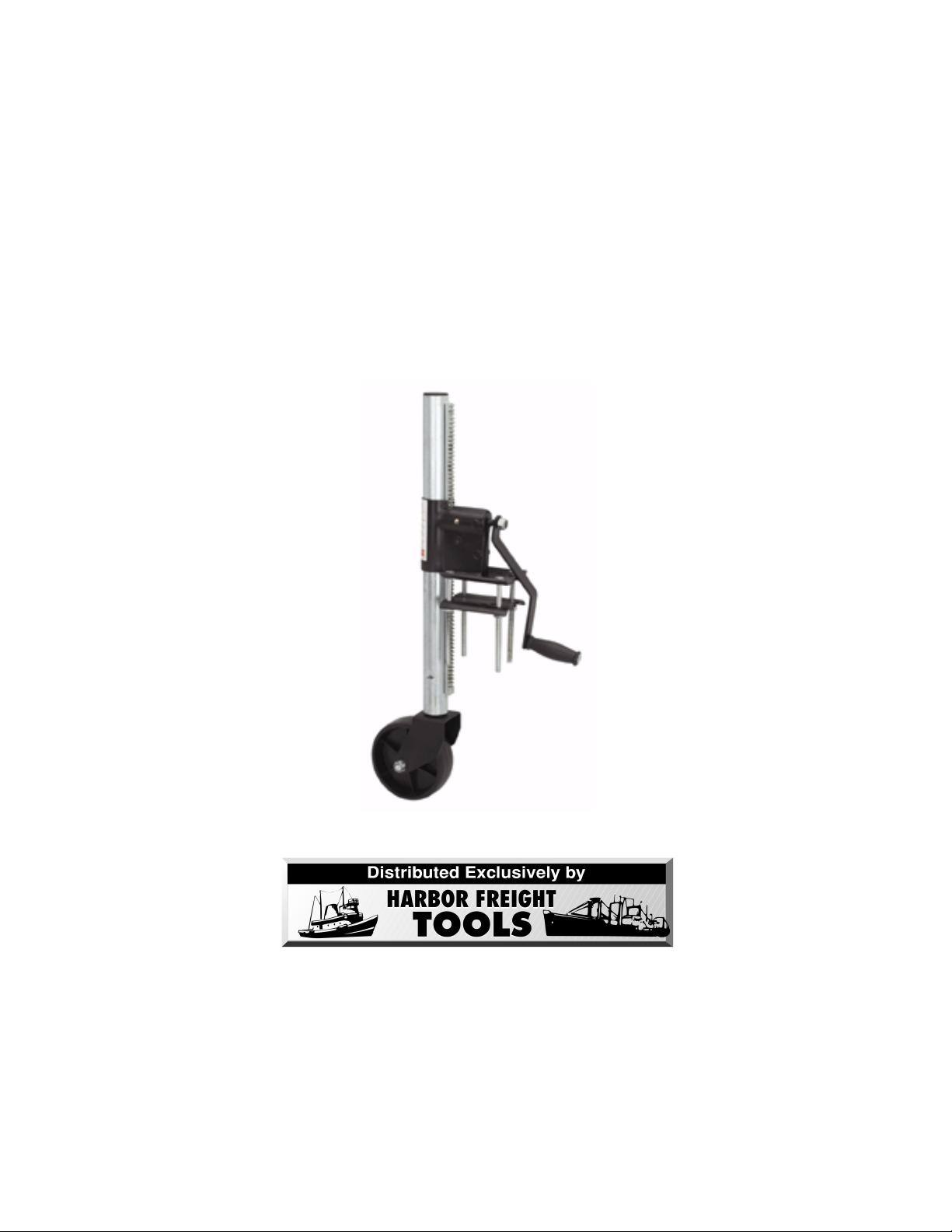
Trailer Jack
®
Model 37792
Assembly and Operating Instructions
3491 Mission Oaks Blvd., Camarillo, CA 93011
Copyright 1998 by Harbor Freight Tools®. All rights reserved. No portion of this manual
or any artwork contained herein may be reproduced in any shape or form without the
express written consent of Harbor Freight Tools.
For technical questions and replacement parts, please call 1-800-444-3353.
Page 2

Important Safety Instructions
READ ALL INSTRUCTIONS AND
W ARNINGS BEFORE USING THIS
PRODUCT .
COMMON SENSE AND CAUTION ARE
F ACTORS WHICH CANNOT BE BUIL T
INTO ANY PRODUCT . THESE F ACT ORS
MUST BE SUPPLIED BY THE OPERA TOR.
PLEASE REMEMBER:
1. When using electric tools, machines or
equipment, basic safety precautions should
always be followed to reduce the risk of fire,
electric shock, and personal injury .
2. Keep work area clean. Cluttered areas
invite injuries.
3. Consider work area conditions. Do not use
machines or power tools in damp, wet, or
poorly lit locations. Do not expose equipment
to rain. Keep work area well lit. Do not use
tools in the presence of flammable gases or
liquids.
4. Keep children away . All children should be
kept away from the work area.
5. Guard against electric shock. Prevent body
contact with grounded surfaces such as pipes,
radiators, ranges, and refrigerator enclosures.
6. Stay alert. Never operate equipment if you
are tired.
7. Do not operate the product if under the
influence of alcohol or drugs. Read warning
labels on prescriptions to determine if your
judgment or reflexes might be impaired.
8. Do not wear loose clothing or jewelry as
they can be caught in moving parts.
9. W ear restrictive hair covering to contain long
hair.
10. Use eye and ear protection. Always wear:
-ANSI approved chemical splash goggles when
working with chemicals.
-ANSI approved impact safety goggles at other
times.
-ANSI approved dust mask or respirator when
working around metal, wood, and chemical
dusts and mists.
-A full face shield if you are producing metal or
wood filings.
11. Keep proper footing and balance at all
times.
12. Do not reach over or across running
machines.
13. Always check that adjusting keys and
wrenches are removed from the tool or machine
work surface before plugging it in.
14. Do not carry any tool with your finger on
either the start button or trigger.
15. When servicing, use only identical replacement parts.
16. Check for damaged parts. Before using
any tool, any part that appears damaged should
be carefully checked to determine that it will
operate properly and perform its intended
function.
17. Check for alignment and binding of all
moving parts, broken parts or mounting fixtures
and any other condition that may affect proper
operation. Any part that is damaged should be
properly repaired or replaced by a qualified
technician.
18. Never force the tool or attachment to do
the work of a larger industrial tool. It is designed to do the job better and more safely at
the rate for which it was intended.
IF THERE IS ANY QUESTION ABOUT A
CONDITION BEING SAFE OR UNSAFE,
DO NOT OPERA TE THE TOOL!
#37792
Page 2
Page 3

Thank you for choosing a Harbor Fr eight T ools product! For future refer ence please complete the owner’s record below:
Model:_______________ Purchase Date:_________________
SAVE THE RECEIPT , WARRANTY AND THESE INSTRUCTIONS. IT IS IMPORTANT THAT
READ THE ENTIRE MANUAL TO BECOME FAMILIAR WITH THIS PRODUCT BEFORE YOU BEGIN ASSEMBLY.
YOU
______________________________________________________________________________
Specifications
Purpose: Jack mounts to side of straight trailer tongue. Once connected to the trailer, the T railer Jack
makes hitching, unhitching, leveling, and moving the trailer a simple and safe procedure. The T railer
Jack can be used on heavy farm duty trailers as well as recreational boat trailers.
The Trailer Jack is designed for permanent or semi-permanent attachment to the trailer tongue, and can
be available for use wherever the trailer goes.
Minimum Height: 8”
Maximum Height: 22 1/2”
Lifting Range: 14 1/2”
Capacity: 550 lbs. load (not including load supported by trailer wheels)
Designed with a heavy duty worm gear drive with built-in gear box. Includes a grease fitting for easy
lubrication.
______________________________________________________________________________
Unpacking
Carefully unpack the Trailer Jack and check all parts against the parts diagram and part number listing
on pages 6. Do not discard any packing material until the Trailer Jack is fully assembled and operational. If any parts are missing or broken, please call Harbor Freight T ools at 1-800-444-3353
Assembly
The Trailer Jack requires some minor assembly . Please follow the steps outlined below:
1. Place the Caster Wheel (#5) into the Caster Bracket (#4). Insert the Axle Bolt (#9), and tighten
with the Locking Nut (#10).
2. Install the wheel assembly shaft into the lower end of the Jack Shaft (#1). Screw in the Bolt (#12),
making sure that the Bolt sets in the grove of the wheel assembly shaft.
3. Place the Crank Handle (#3) on the shaft of the Jack Shaft, and align the flat surface to the handle.
#37792 Page 3
Page 4

Assembly (continued)
Screw on the Locking Nut (#11) and tighten the nut securely .
4. Plan the location of the Trailer Jack. Examine both sides of the trailer tongue and choose the appropriate location for the jack, keeping in mind the mounting method, and the need to turn the Crank
Handle. The T railer Jack is designed to be mounted on either side of the trailer tongue, and pivot in
either direction (caster wheel forward or to the rear).
5. Before installing the Trailer Jack, properly support the tongue of the trailer so that it is high enough
off the ground to provide clearance for the jack. T ake precautions to insure the trailer is blocked and
will not roll.
6. Position the Trailer Tongue Assembly portion of the T railer Jack on top of the tongue. Position the
loose plate of the Trailer Tongue Assembly underneath the tongue. Insert bolts through the top plate
and through to the bottom plate. Note the hole selections on the loose plate. Use the hole positions
which will best support your trailer tongue design. Install lock washers and nuts. At this time tighten
nuts only enough to hold the Trailer Jack in position for adjustment.
7. Inspect the position of the Trailer Jack. Check the squrareness of the mount position, and tap lightly
into alignment with a hammer and a wood block if necessary . Bolts should be at right angles to the
mounting plates. There should be proper clearance of the trailer tongue from the Jack Shaft. Once
determined that the Trailer Jack is properly positioned, tighten the nuts evenly , increasing pressure by
small increments on alternate bolts so that the mounting plates remain parallel. Nuts should be more
than tight enough to fully compress the washers, but not tight enough to damage the threads. Turn the
Crank Handle both ways to make sure the Trailer Jack is functioning properly .
8. Before operating the Trailer Jack, lubricate the grease fitting on the side of the Trailer T ongue Assembly . Use a good quality gear grease. Lubricate periodically while the Trailer Jack is in use.
Read and understand carefully the warnings and cautions described below as they pertain to
the operation of the T railer Jack:
1. Be aware that the user/installer of this product is solely responsible for the way the Trailer
Jack is installed, operated and maintained, and is
responsible for any and all consequences that
occur, whether or not anticipated in these
warning statements.
2. Never exceed the rated load capacity of 550
lbs. for the jack.
3. Never loosen, adjust, or take apart the top
and bottom plates of the Trailer Tongue Assembly while the Trailer Jack is supporting any
weight.
4. Before each use, verify that the plates of the
Trailer T ongue Assembly and the trailer tongue
#37792 Page 4
are securely attached, and that all bolts and nuts
are tight and in good condition.
5. Always keep feet, arms, and legs out from
under the trailer tongue while hitching, unhitching, or moving the trailer . Children should be
kept at a safe distance, and should never be
allowed to operate the Trailer Jack.
6. Always take precautions to prevent uncontrolled movement of the trailer when the Trailer
Jack is being used. Be cautious of the slope of
the road and be aware of the pull of gravity
when using this product.
Page 5

Operation
Unhitching:
T o use the Trailer Jack as an aid in unhitching the trailer , first make sure that the Trialer Jack is securely
attached to the trailer tongue. Check out bolt/nut connection to make sure the Trailer T ongue Assembly
is properly connected to the trailer tongue.
T ake the neccessary precautions against uncontrolled trailer movement, and loosen the trailer hitching
mechanism. Attach the Crank Handle, if it has been detached in prior use, and turn the handle clockwise to increase the length of the Trailer Jack until the tongue has been lifted from the hitch ball. Keep
all body parts clear of the hitch, the tongue, and the area underneath the tongue.
Hitching:
T o use the Trailer Jack as an aid in hitching the trailer , maneuver the trailer so that the trailer’s hitch is
directly over the towing vehicle’ s hitch ball. Turn the Crank Handle counterclockwise to shorten the
Trailer Jack, and lower the tongue hitch onto the hitch ball. T ighten the hitch retainer mechanism.
Continue turning the Crank Handle until the Trailer Jack is fully retracted.
It is recommended that the Crank Handle be detached in preparation for towing. Keep all body parts
clear of the hitch, the tongue, and the area underneath.
Leveling and Moving:
In the unhitched mode, the trailer can be leveled or adjusted in pitch angle by turning the Crank Handle
in either clockwise or counterclockwise direction to lengthen or shorten the Trailer Jack. In this mode,
the trailer is a three wheeled vehicle that can be moved from one position to another, but only with
suitable precautions against uncontrolled movement. If the trailer is to be stored in this mode, it is
advised that the Crank Handle be detached and that the trailer wheels be properly blocked.
T owing:
When the Trailer Jack is attached while the trailer is being towed, the Trailer Jack must be fully retracted
(before towing begins, turn the Crank Handle counterclockwise until the Trailer Jack is fully retracted).
The Crank Handle needs to be removed and stored in a safe place while the trailer is being towed.
#37792 Page 5
Page 6

Part Number Listing and Parts Diagram
Grease Fitting
Part # Description Quantity
1 Jack Shaft 1
2 Trailer T ongue Assembly 1
3 Crank Handle 1
4 Caster Bracket 1
5 Caster Wheel 1
6 Bolt M10 x 120 4
7 Nylon Locking Nut M10 4
8 Washer 4
9 Bolt M12 x 80 1
10 Nylon Locking Nut M12 1
11 Nylon Locking Nut M12 1
12 Bolt M6 x 20 1
#37792 Page 6
 Loading...