

Page 1
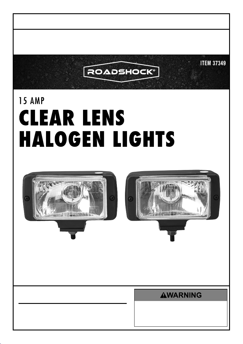
Owner’s Manual & Safety Instructions
Save This Manual Keep this manual for the safety warnings and precautions, assembly,
operating, inspection, maintenance and cleaning procedures. Write the product’s serial number in the
back of the manual near the assembly diagram (or month and year of purchase if product has no number).
Keep this manual and the receipt in a safe and dry place for future reference.
REV 15c
Email our technical support at: productsupport@harborfreight.com
When unpacking, make sure that the product is intact
and undamaged. If any parts are missing or broken,
please call 1-888-866-5797 as soon as possible.
Copyright© 2015 by Harbor Freight Tools®. All rights reserved.
No portion of this manual or any artwork contained herein may be reproduced in
any shape or form without the express written consent of Harbor Freight Tools.
Diagrams within this manual may not be drawn proportionally. Due to continuing
improvements, actual product may differ slightly from the product described herein.
Tools required for assembly and service may not be included.
Visit our website at: http://www.harborfreight.com
Read this material before using this product.
Failure to do so can result in serious injury.
SAVE THIS MANUAL.
Page 2
Specifications
Electrical Rating 15 A
Bulb
12 V 55 W H3 Halogen
(included)
IMPORTANT SAFETY INFORMATION
Installation Precautions
1. A 15 amp fuse must be installed
inline on the positive power supply
wire of this item. Using no fuse, or
using an incorrect fuse can cause an
electrical fire.
2. Install only according to these instructions.
Improper installation can create hazards.
3. Wear ANSI-approved safety goggles and
heavy-duty work gloves during installation.
4. Make certain the vehicle’s engine is
turned off and battery is disconnected
before installing the Lights.
5. When drilling holes, beware of any
hidden electrical lines or cables. Make
sure you don’t damage or weaken the
structural integrity of the vehicle.
6. Vehicles equipped with airbags may
have the sensors located inside the front
bumper. Consult the vehicle owner’s
manual to determine the location of the
airbag sensors. To avoid damaging the
sensors if they are located in the front
bumper, do not drill holes in the bumper.
7. Do not install Lights where they could restrict
sufficient airflow to the radiator or obstruct the
headlights and/or turn signals of vehicle.
8. Keep installation area clean and well lit.
9. Keep bystanders out of the
area during installation.
10. Do not install when tired or when under the
influence of alcohol, drugs or medication.
11. Read all instructions and safety
precautions in the vehicle’s manual onto
which the Lights will be installed.
12. Install on negative ground 12 VDC systems only.
13. Do not install this product yourself
unless you are technically competent
to do so. If necessary, have a qualified
technician install the Lights.
14. WARNING: The cord of this product contains
lead and/or di (2-ethylhexyl) phthalate
(DEHP), chemicals known to the State
of California to cause cancer, and birth
defects or other reproductive harm. Wash
hands after handling. (California Health
& Safety Code § 25249.5, et seq.)
15. WARNING: This product contains or, when
used, produces a chemical known to the State
of California to cause cancer and birth defects
or other reproductive harm. (California Health
& Safety Code § 25249.5, et seq.)
16. WARNING: This product contains
di (2-ethylhexyl) phthalate (DEHP), a
chemical known to the State of California
to cause cancer and birth defects or other
reproductive harm. (California Health
& Safety Code § 25249.5, et seq.)
Use Precautions
1. This product is not a toy. Do not allow
children to play with this item.
2. The Halogen Lights become very hot during
continuous use. Do not touch the Lights
for at least half an hour after turning off.
Page 2 For technical questions, please call 1-888-866-5797. Item 37349
3. Inspect before every use; do not use
if parts are loose or damaged.
4. Use as intended only. Do not modify
this product or use it for a purpose
for which it was not intended.
Page 3

5. This product may not meet D.O.T. requirements
for use on public roads or highways. Follow
local, state, and federal regulations.
6. The warnings and precautions discussed in this
manual cannot cover all possible conditions
and situations that may occur. The operator
must understand that common sense and
caution are factors that cannot be built into this
product, but must be supplied by the operator.
Installation Instructions
Read the ENTIRE IMPORTANT SAFETY INFORMATION section at the beginning of this
document including all text under subheadings therein before set up or use of this product.
Note: For additional information regarding the parts listed in the following pages,
refer to Parts List and Diagram on page 6.
Light Mounting
1. To avoid accidental short circuits,
disconnect the negative (-) terminal of
the vehicle battery prior to installation.
2. Driving lights must be mounted between 16"
and 42" from the ground. Fog lights must be
mounted between 12" and 30" from the ground.
Check state and local regulations for minimum
and maximum mounting height requirements.
3. The Halogen Lights can be mounted above
or below the bumper. Make sure the
desired mounting locations do not obstruct
the vehicle’s headlights or turn signals.
4. If mounting below the bumper, perform
following procedure to maintain
the optimum beam pattern:
a. Remove two Screws (1), Lens
Holders (2), and the Glass Lens (3)
from the front of each Light.
b. Pull out the Reflector (5) from the Light
Housing (8), turn 180 º and put back into
the Housing in the reverse position.
c. Turn the Glass Lens 180 º, reinstall on
the Light Housing and secure in place
with the Lens Holders and Screws.
5. Place the Halogen Lights on the bumper, and
mark the desired mounting locations at an
equal distance from the center of the bumper.
6. Drill 1/2" diameter holes through
pre-marked mounting positions.
CAUTION: Make sure no electrical wires or
cables are in the way of the drilling path.
7. Install the Lights on the bumper, using
the Bolts (10), Attachment Plates (11),
Lock Washers (12), and Nuts (13).
8. Align Lights to desired angle and tighten
the Nuts to retain aiming position.
9. Mount the Light Switch (14) in a location
that is within easy reach (i.e., dashboard,
console). With the Light Switch in the
desired position, mark the holes for drilling
and drill two 1/16" holes. Mount the Light
Switch with the Screws provided.
Page 3For technical questions, please call 1-888-866-5797.Item 37349
Page 4

Wiring Installation
1. Connect the Black ground wire from
each Light to the chassis or any other
grounded metal surface of the vehicle.
2. Insert the male connector end of the White
bulb wire from one Light into double female
"Y" connector of 6 ft. White extension wire.
3. Insert the male connector end of the White
bulb wire from the other Light into single
female connector of 3 ft. Blue extension wire.
4. Insert the male connector end of Blue
extension wire into double female "Y"
connector of White extension wire.
5. Insert "U" spade connector end of White
extension wire into one Light Switch terminal.
Lamp
Black
ground
White bulb
wire
wire
6. Insert "U" spade connector end of 5 ft.
Black power supply wire with 15 A in‑line
fuse into other Light Switch terminal. The
other end of the Black power supply wire
must be connected to the positive (+)
terminal of battery or vehicle fuse box.
7. Use plastic tie-strips (not included) to secure
the wiring throughout the vehicle. Avoid hot
areas and moving parts. Tape all connections
using electrical tape (not included). Protect the
wiring from sharp edges with tape or grommets.
8. A 15 amp fuse must be installed
9. Check that all wiring is identical with
Figure A: Wiring Diagram, then reconnect
negative (-) terminal of the vehicle battery.
Turn on the Light Switch to confirm
the Lights are operating properly.
inline on the positive power supply
wire of this item. Using no fuse, or
using an incorrect fuse can cause an
electrical fire.
Lamp
Black
ground
White bulb
wire
"Y" Connector
wire
To ground
Blue
extension
To ground
wire
White extension wire
Light
Switch
Figure A: Wiring Diagram
Page 4 For technical questions, please call 1-888-866-5797. Item 37349
15 A Fuse
Black power supply wire
To fuse box
or positive (+)
terminal of battery.
Page 5

Aiming Beams
1. Driving lights must be aimed with the center of
the high intensity zone on a vertical line, straight
ahead of the light center and with the top edge
of the beam 2 inches below the level of the light
center at a distance of 25 feet from the lens.
Halogen Bulb Replacement
1. To avoid accidental short circuits, disconnect
the negative (-) terminal of the vehicle
battery prior to bulb replacement.
2. Disconnect the White bulb wire from the
double female "Y" connector of the 6 ft. White
extension wire or from the single female
connector of the 3 ft. Blue extension wire
(depending on which bulb is being replaced).
Refer to Figure A: Wiring Diagram.
3. Remove two Screws (1), Lens Holders (2), and
the Glass Lens (3) from the front of the Light.
Refer to Parts List and Diagram on page 6.
4. Pull out the Reflector (5) from the Light
Housing (8). Remove the Screw (7)
holding the Bulb (6) and Black ground
wire in place on the Reflector.
5. Remove the old Bulb from the
Reflector and replace with an identical
12 V 55 W H3 halogen bulb.
CAUTION: Do not touch the Bulb with your bare
hands; oil from skin will drastically shorten the life
span of the bulb if not cleaned with rubbing alcohol
and allowed to dry before use. Handle the bulb with
a soft, clean cloth or clean work gloves instead.
2. Fog lights must be aimed with the center of the
high intensity zone on a vertical line straight
ahead of the lamp center and with the top edge
of the beam 4 inches below the level of the light
center at a distance of 25 feet from the lens.
NOTICE: Incorrectly aiming beams may present
a hazard to other drivers and may be illegal.
Follow local, state, and federal regulations.
6. Secure the new Bulb and existing Black
ground wire in place with the Screw.
7. Thread the new White bulb wire through
the Grommet (9) on the Light Housing and
insert the Reflector back into the Housing.
Replace the Glass Lens and Lens Holders.
Secure in place with the two Screws.
8. Insert the male connector end of the
White bulb wire into the double female
"Y" connector of the 6 ft. White extension
wire or into the single female connector
of the 3 ft. Blue extension wire.
9. Check that all wiring is identical with
Figure A: Wiring Diagram, then reconnect
negative (-) terminal of the vehicle battery.
PLEASE READ THE FOLLOWING CAREFULLY
THE MANUFACTURER AND/OR DISTRIBUTOR HAS PROVIDED THE PARTS LIST AND ASSEMBLY
DIAGRAM IN THIS DOCUMENT AS A REFERENCE TOOL ONLY. NEITHER THE MANUFACTURER
OR DISTRIBUTOR MAKES ANY REPRESENTATION OR WARRANTY OF ANY KIND TO THE
BUYER THAT HE OR SHE IS QUALIFIED TO MAKE ANY REPAIRS TO THE PRODUCT, OR
THAT HE OR SHE IS QUALIFIED TO REPLACE ANY PARTS OF THE PRODUCT. IN FACT, THE
MANUFACTURER AND/OR DISTRIBUTOR EXPRESSLY STATES THAT ALL REPAIRS AND PARTS
REPLACEMENTS SHOULD BE UNDERTAKEN BY CERTIFIED AND LICENSED TECHNICIANS,
AND NOT BY THE BUYER. THE BUYER ASSUMES ALL RISK AND LIABILITY ARISING OUT OF
HIS OR HER REPAIRS TO THE ORIGINAL PRODUCT OR REPLACEMENT PARTS THERETO,
OR ARISING OUT OF HIS OR HER INSTALLATION OF REPLACEMENT PARTS THERETO.
Page 5For technical questions, please call 1-888-866-5797.Item 37349
Page 6

Parts List and Diagram
Parts List
Part Description
1 Screw ST4 x 20
2 Lens Holder
3 Glass Lens
4 Gasket
5 Reflector
6 12 V 55W H3 Halogen Bulb
7 Screw ST3 x 6
8 Light Housing
Part Description
9 Grommet
10 Bolt M8 x 25
11 Attachment Plate
12 Lock Washer D8
13 Nut M8
14 Light Switch (not shown)
15 Wire Bundle (not shown)
Record Serial Number Here:
Note: If product has no serial number, record month and year of purchase instead.
Note: Some parts are listed and shown for illustration purposes only,
and are not available individually as replacement parts.
Page 6 For technical questions, please call 1-888-866-5797. Item 37349
Page 7

Assembly Diagram
Page 7For technical questions, please call 1-888-866-5797.Item 37349
Page 8

Limited 90 Day Warranty
Harbor Freight Tools Co. makes every effort to assure that its products meet high quality
and durability standards, and warrants to the original purchaser that this product is free from
defects in materials and workmanship for the period of 90 days from the date of purchase. This
warranty does not apply to damage due directly or indirectly, to misuse, abuse, negligence or
accidents, repairs or alterations outside our facilities, criminal activity, improper installation,
normal wear and tear, or to lack of maintenance. We shall in no event be liable for death,
injuries to persons or property, or for incidental, contingent, special or consequential damages
arising from the use of our product. Some states do not allow the exclusion or limitation of
incidental or consequential damages, so the above limitation of exclusion may not apply to
you. THIS WARRANTY IS EXPRESSLY IN LIEU OF ALL OTHER WARRANTIES, EXPRESS
OR IMPLIED, INCLUDING THE WARRANTIES OF MERCHANTABILITY AND FITNESS.
To take advantage of this warranty, the product or part must be returned to us with
transportation charges prepaid. Proof of purchase date and an explanation of the complaint
must accompany the merchandise. If our inspection verifies the defect, we will either repair or
replace the product at our election or we may elect to refund the purchase price if we cannot
readily and quickly provide you with a replacement. We will return repaired products at our
expense, but if we determine there is no defect, or that the defect resulted from causes not
within the scope of our warranty, then you must bear the cost of returning the product.
This warranty gives you specific legal rights and you may also
have other rights which vary from state to state.
3491 Mission Oaks Blvd. • PO Box 6009 • Camarillo, CA 93011 • 1-888-866-5797
 Loading...