

Page 1

WOOD BANDSAW
®
14” W/DUST COLLECTOR
Models 32206/32208
OPERATING INFORMATION
3491 Mission Oaks Blvd., Camarillo, CA 93011
Visit our website at http://www .harborfreight.com
Copyright
manual or any artwork contained herein may be reproduced in an y shape or form
For technical questions or replacement parts, please call 1-800-444-3353.
©
2001 by Harbor Freight T ools®. All rights reserved. No portion of this
without the express written consent of Harbor Freight Tools.
Page 2

SPECIFICATIONS
ITEM DESCRIPTION
Net Weight
Speeds
Motor
Electrical Requirements
Cutting Capacity
Blade Thickness Ranges
Table Dimensions
Table Adjustments
Dust Collector Accessory
160 Lbs.
3000 RPM (Model 32206) / 600, 1140, 1670, 2670 RPM (Model 32208)
Motor: 1 HP / Single Phase
110V / 9 Amps
6”
1/8” to 3/4”
Approx. 14” x 14”
0
Tilts 45
Dust Chute Attachment Only (Dust Bag Not Provided)
to Right / 150 to Left
SAVE THIS MANUAL
You will need the manual for the safety warnings and precautions, assembly
instructions, operating and maintenance procedures, parts list and diagrams. K eep
your in voice with this manual. Write the in voice number on the inside of the front
cover. Keep the manual and invoice in a safe and dry place for future reference.
GENERAL SAFETY WARNINGS AND PRECAUTIONS
1. KEEP WORK AREA CLEAN AND DRY. Cluttered, damp or wet work areas invite
injuries.
2. KEEP CHILDREN AWAY FRO M WORK AREA. Do not allow children to handle
this product.
3. STORE IDLE EQUIPMENT. When not in use, tools and equipment should be
stored in a dry location to inhibit rust. Always lock up tools and equipment and keep
out of reach of children.
4. DO NOT USE THIS PRODUCT IF UNDER THE INFLUENCE OF ALCOHOL OR
DRUGS. Read warning labels on prescriptions to determine if your judgment or
reflexes are impaired while taking drugs. If there is any doubt, do not attempt to
use this product.
SKU 32208/32206 For technical questions, please call 1-800-444-3353. PAGE 2
Page 3

5. USE EYE, HEARING, AND BREATHING PROTECTION. Wear ANSI approved
safety impact eye glasses, ANSI approved hearing protection, and ANSI approved
dust mask or respirator when using this product. ANSI approved safety impact eye
glasses, hearing protection, and dust masks and respirators are available from
Harbor Freight Tools.
6. DRESS SAFELY. Non-skid footwear or safety shoes should be used when working
with this product. Do not wear loose clothing or jewelry as they can become caught
in moving parts. Wear a protective hair covering to prevent long hair from becoming
caught in moving parts. If wearing a long-sleeve shirt, roll sleeves up above elbows.
7. INDUSTRIAL APPLICATIONS MUST FOLLOW OSHA REQUIREMENTS.
8. DO NOT OVERREACH. Keep proper footing and balance at all times to prevent
tripping, falling, back injury, etcetera.
9. STAY ALERT. Watch what you are doing at all times. Use common sense. Do not
use this product when you are tired or distracted from the job at hand.
10. CHECK FOR DAMAGED PARTS. Before using this product, carefully check that it
will operate properly and perform its intended function. Check for damaged parts
and any other conditions that may affect the operation of this product. Replace or
repair damaged or wo rn parts immediately.
11. REPLACEMENT PA RTS AND ACCESSORIES. When servicing, use only identical
replacement parts. Only use accessories intended for use with this product.
Approved accessories are available from Harbor Freight Tools.
12. MAINT AIN THIS PRODUCT WITH CARE. Keep this tool clean and dry, and keep
saw blades clean and sharp for better and safer performance.
13. MAINTENANCE: For your safety, ser vice and maintenance should be performed
regularly by a qualified technician.
14. USE THE RIGHT PRODUCT FOR THE RIGHT JOB. There are certain applications
for which this product was designed. Do not use small equipment, tools or attach-
ments to do the work of larger industrial equipment, tools or attachments. Do not
use this product for a purpose for which it was not intended.
SPECIFIC PRODUCT WARNINGS AND PRECAUTIONS
1. GROUND THIS PRODUCT . The electrical power cord for this product is equipped
with a grounded 3-prong plug. Never remove the grounding prong or modify the
plug in any way. Do not use adapter plugs with this product. When in use, make
sure this product is always plugged into a grounded 3-hole electrical receptacle with
an appropriate breaker switch inline.
SKU 32208/32206 For technical questions, please call 1-800-444-3353. PAGE 3
Page 4

2. MAKE SURE THE POWER SWITCH IS IN THE “OFF” POSITION BEFORE
PLUGGING IN THE POWER CORD.
3. DO NOT ABUSE THE POWER CORD. Do not use the cord to pull the 3-prong
plug from a power outlet. Keep cord away from heat, oil, sharp edges, and moving
par ts. Replace damaged cord immediately. Route the power cord safely. Protect
it from being damaged by other equipment in the shop. Do not route the cord where
it can be walked on or tripped over.
4. IF YOU USE AN EXTENSION CORD, MAKE SURE TO USE ONLY UL AP-
PROVED CORDS HAVING THE CORRECT GAUGE AND LENGTH.
(SEE FIGURE A.)
FIGURE A
5. MAINTAIN A SAFE WORK ENVIRONMENT. Do not use this product in or near
damp or wet areas. Do not expose this product to rain. Keep work area well lit.
Make sure there is adequate surrounding work space. Use this product in a well
ventilated area. Do not operate this product in the presence of flammable liquids,
gases, or dust. To avoid accidental electric shock, do not let your body come in
contact with grounded surfaces such as pipes, radiators, ranges and refrigerators.
6. DO NOT FORCE THE EQUIPMENT. This Bandsaw will do the work better and
safer at the speed and capacity for which it was designed.
7. KEEP ALL GUARDS IN PLACE AND IN WORKING ORDER.
8. REMOVE ALL ADJUSTING WRENCHES FROM THE BANDSAW BEFORE
TURNING IT ON.
9. MAKE SURE THA T WHEN INSTALLING THE SAW BLADE THE SAW TEETH
POINT DOWNWARD AND TOWARD THE TABLE (36) OF THE BANDSAW.
SKU 32208/32206 For technical questions, please call 1-800-444-3353. PAGE 4
Page 5

10. AVOID UNINTENTIONAL STARTING. Make sure you are prepared to begin work
before turning the START switch on.
11. DO NOT USE THIS TOOL FOR CUTTING METALS OR BRITTLE MATERIALS.
Do not cut dangerous materials, such as asbestos which can cause harmful dust or
vapors.
12. CAUTION: Some woods contain preservatives such as copper chromium arsenate
(CCA) which can be toxic. When cutting these materials extra care should be taken
to avoid inhalation and minimize skin contact.
13. BEFORE USING THE BANDSAW, MAKE SURE THE SAW BLADE IS PROPERLY
MOUNTED. Make sure the saw blade is balanced, its tension and tracking are
properly adjusted, its teeth point downward, and it is not bent or cracked.
14. ALLOW THE SAW BLADE TO SPIN UP TO FULL SPEED BEFORE FEEDING
WOOD INTO IT. When turning it off, allow the saw blade to spin down and stop on
its own. Do not press against the saw blade to stop it.
15. DO NOT FORCE THE MATERIAL INTO THE SAW BLADE WHEN CUTTING.
Apply moderate pressure, allowing the saw blade to cut without being forced.
16. NEVER ATTEMPT TO REMOVE MATERIAL STUCK IN THE MOVING
PARTS OF THE BANDSAW WHILE THE SAW IS PLUGGED IN AND RUNNING.
17. THE SAW BLADE WILL BECOME HOT WHILE CUTTING. Allow the saw blade
to completely cool before touching.
18. WHENEVER POSSIBLE, USE CLAMPS OR OTHER SAFE, PRACTICAL WAYS
TO HOLD AND SUPPORT THE WORKPIECE. Do not attempt to saw material that
does not have a flat surface, unless a suitable support is used.
19. ADJUST THE BLADE GUIDE (29) about 1/8” (3.2mm) above the material being cut.
20. TURN OFF THE BANDSAW IF THE MATERIAL IS TO BE BACKED OUT OF AN
UNCOMPLETED CUT .
21. MAKE “RELIEF” CUTS BEFORE CUTTING LONG CURVES.
22. ALWAYS KEEP HANDS AND FINGERS AWAY FROM BLADE.
23. ALWAYS DISCONNECT THE BANDSAW FROM ITS ELECTRICAL SUPPLY
SOURCE BEFORE PERFORMING ANY SERVICES OR MAINTENANCE such as
leaving the work area, moving the tool from one location to another, changing the
saw blade, cleaning sawdust from the unit, etcetera.
SKU 32208/32206 For technical questions, please call 1-800-444-3353. PAGE 5
Page 6
UNPACKING
When unpacking, check to make sure all parts shown on the Parts List (pages 20,
22, 23, 24, 25 and 26) are included. If any parts are missing or broken, please
call Harbor Freight Tools at the number shown on the cover of this man ual as soon
as possible.
OPERATING INSTRUCTIONS
NOTE: For additional references to the parts listed belo w , refer to pages 20,
through 28 of this manual.
To Assemble The Stand:
1. NOTE: During the following 7 steps,
ger tighten
all Bolts and Nuts.
loosely fin-
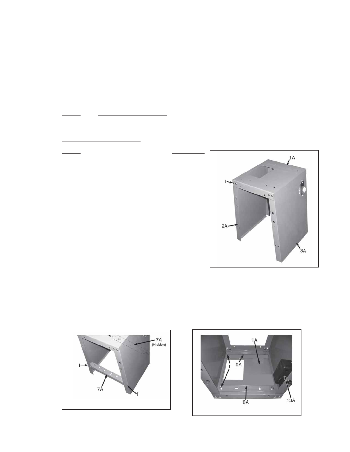
2. Set the Front and Back Stands (2A, 3A) upright
with the two square holes nearest the edge at
the top. Attach the Face Plate (1A) over the top
of the Front and Bac k Stands (2A, 3A), using the
Carriage Bolts, W ashers, and Nuts (I). (See Fig-
ure B and Hardware Diagram.)
3. Attach the two Support Plates (7A) inside each
side of the Front and Back Stands (2A, 3A), using the Carriage Bolts, Washers, and Nuts (I).
(See Figure C and Hardware Diagram.)
4. Attach the Motor Plate Bracket (9A) to the front
FIGURE B
of the Face Plate (1A) with the raised section of
it towards the middle, using the Carriage Bolts, Washers, and Nuts (I). (Note the location of the Switch Cover (13A) in relation to the mounting position.)
(See Figure D and Hardware Diagram.)
5. Attach the Stiffening Plate (8A) to the underside and toward the rear of the Face Plate
(1A), using the Carriage Bolts, Washers, and Nuts (I). (See Figure D, Assembl y Dia-
gram A, and Hardware Diagram.)
FIGURE C
FIGURE D
View from
Underneath
REV 03/04; 07/04; 12/05
SKU 32208/32206 For technical questions, please call 1-800-444-3353. PAGE 6
Page 7
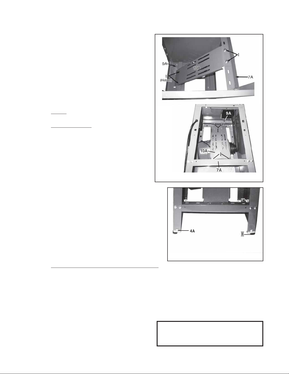
6 . Attach one end of the Motor Plate (10A)
to the Motor Plate Bracket (9A), using the
Hex Bolts, Washers, Spring Washers,
and Nuts (I). (See Figure E and Hard-
ware Diagram.)
7. Attach the other end of the Motor Plate
(10A) to the rear Support Plate (7A), using the Hex Bolts, Washers, Spring
Washers, and Nuts (I). (See Figure E
and Hardware Diagram.)
View from
Underneath
8.
NOTE: Check to make sure the Stand is
setting square on the floor. Then,
wrench tighten
all Bolts and Nuts se-
curely.
9 . Insert two Lock Pieces (4A) into the two
holes located on the underneath of each
end of the Front Stand (2A). Inser t the
remaining two Lock Pieces (4A) into the
two holes located on the underneath of
each end of the Back Stand (3A).
(See Figure F and Hardware Diagram.)
10. Attach the four Stand Assemblies (II) to
the four Lock Pieces (4A). (See Figure
F and Hardware Diagram.)
Side View
(Motor
already
mounted)
FIGURE E
FIGURE F
To Assemble The Motor Onto The Stand:
1. Note: F or both the Model 32208 Band Saw and the Model 32206 Band Saw , make sure
to attach the Motor Pulley (3D , Model 32208 - part #1C, Model 32206 onto the Shaft of
the Motor (11A) before proceeding with the following instructions. Also, for the Model
32208 Band Saw, make sure to attach the Motor Pulley (3D) with its largest diameter
closest to the Motor. (See Figure E)
2. Attach the Motor (11A) to the Motor Plate (10A), using the four Hex Bolts, Washers,
Spring W ashers, and Nuts (IV). Note: During this step loosely finger tighten the Bolts
and Nuts. (See Figures G and H on page
8, and the Hardware Diagram on page
27.)
Note: Attach both 8A and 9A underneath the
Face Plate (#1A) - see Assembly Diagram
A on page 20 for clearer view.
REV 03/04; 07/04; 02/05; 12/05
SKU 32208/32206 For technical questions, please call 1-800-444-3353. PAGE 7
Page 8
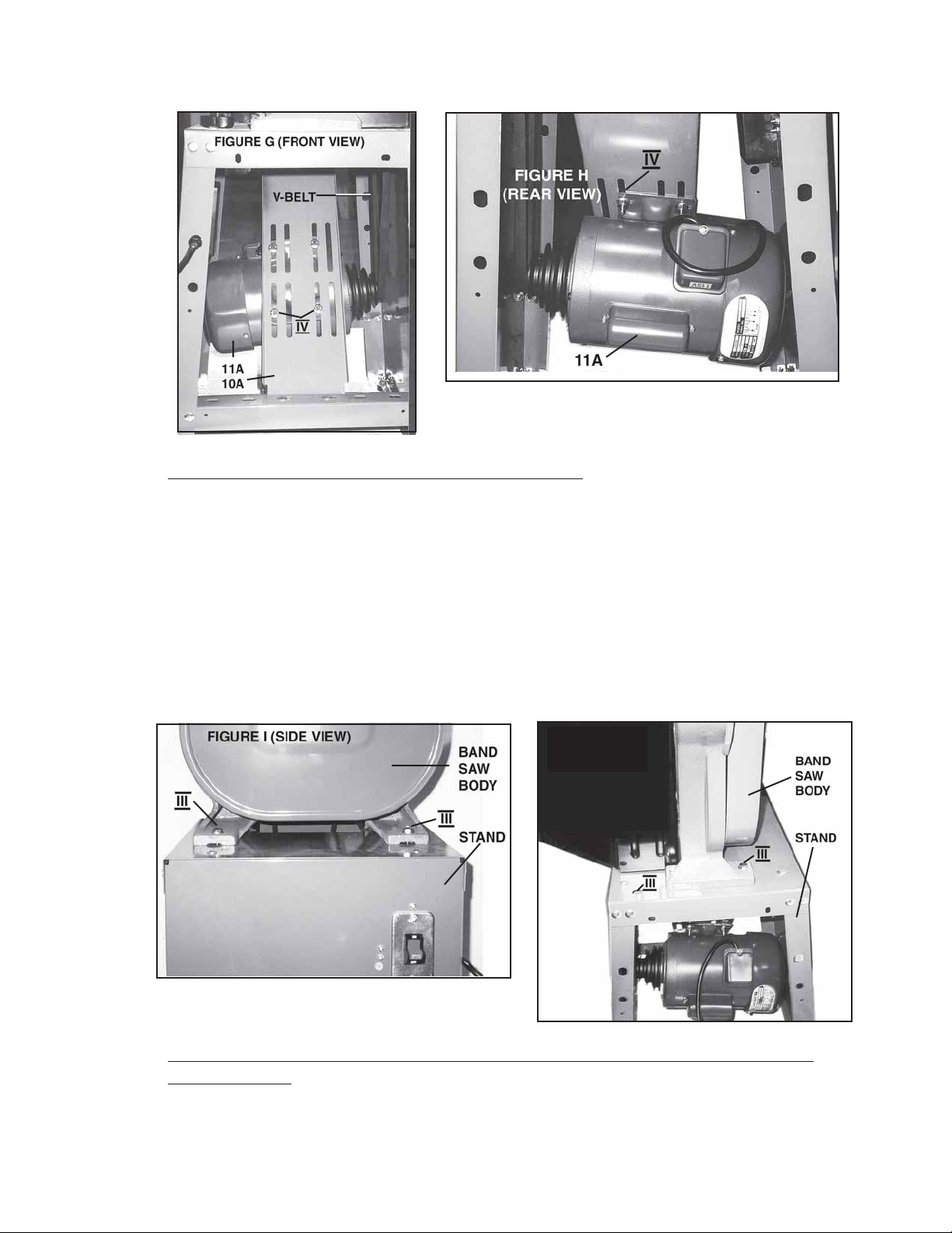
FIGURE H (REAR VIEW)
To Assemble The Bandsaw Body To The Stand:
1. With additional help, set the Bandsaw Body on the Stand. Make sure the Table
(36B) faces to the
2. Align the four mounting holes on the Base (2B) of the Bandsaw Body with the holes
located on the Face Plate (1A) of the Stand.
3. Attach the Bandsaw Body securely to the Stand, using the four Hex Bolts, Washers ,
Spring W ashers, and Nuts (III). (See Figures I, J , and Hard ware
Diagram.)
front
of the Stand.
FIGURE J
FIGURE I
REAR
VIEW
To Mount The V-Belt Onto The Belt Pulle y And Motor Pulley - Model 32206/
Single Speed:
1. Open the Side Panel Door (38A). (See Figure K.)
SKU 32208/32206 For technical questions, please call 1-800-444-3353. PAGE 8
Page 9
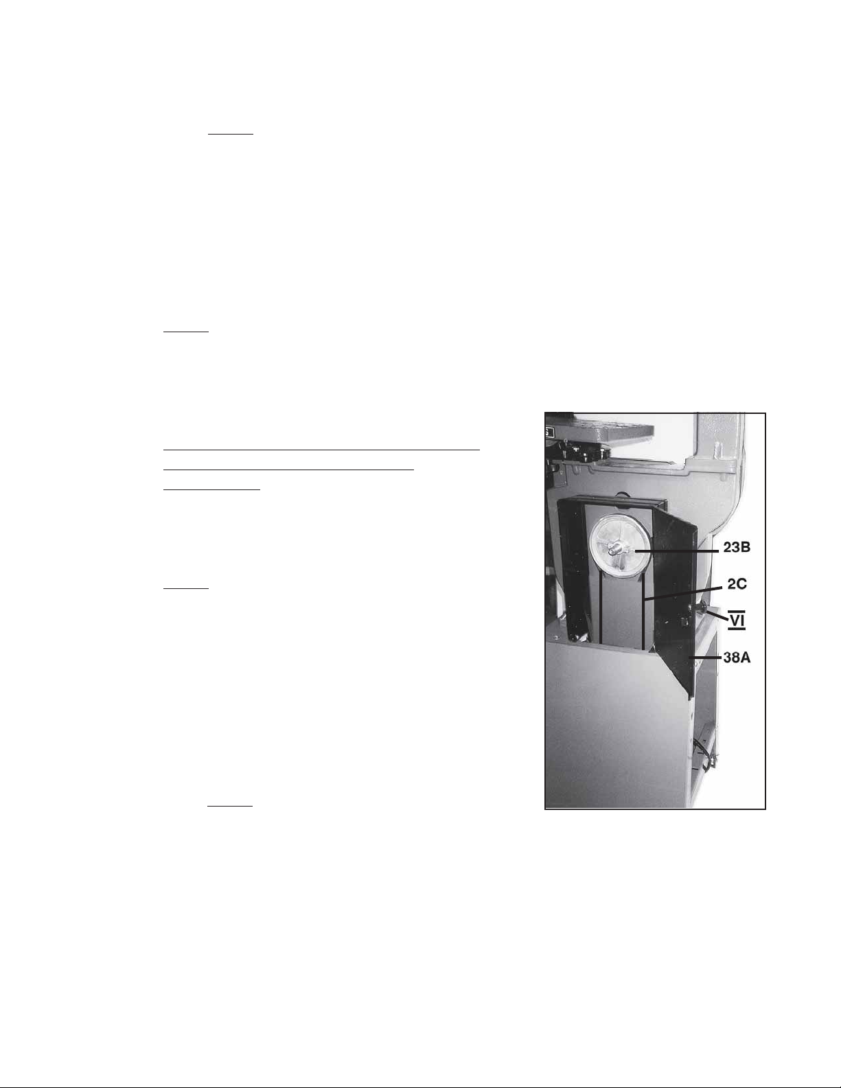
2. Place the V-Belt (2C) onto the Belt Pulley (23B) and also onto the Motor Pulley
(1C). NOTE: During this step , y ou may need to push the Motor (11A) upward along
the groov es in the Motor Plate (10A) in order to mount the V-Belt onto the Motor
Pulley. (See Figures G and H.)
3. To adjust the V -Belt (2C) to its proper tension, pull down on the Motor (11A). While
pulling down on the Motor, push in on the V-Belt with your finger until the V -Belt can
only be pushed in about 1/2”. While holding the Motor in place, wrench tighten the
Motor (11A) to the Motor Plate (10A) with the four Hex Bolts, Washers, Spring
Washers, and Nuts ( IV). (See Figures G and H.)
4. NOTE: For additional technical information, see Figure M.
5. While the Side Panel Door (38A) is still open, attach the Knob (VI) to the Door .
Then, close the Side Panel Door securely. (See Figure K and Hard ware Dia-
gram.)
FIGURE K
To Mount The V-Belt Onto The Belt Pulley
And Motor Pulley - Model 32208/
Four Speed:
1. Open the Side Panel Door (38A).
(See Figure K.)
2.
3. Place the V-Belt (5D) onto the Belt Pulley
4. Place the other V-Belt (4D) onto the Middle
5. To adjust the V -Belt (4D) to its proper tension, pull down on the Motor (11A). While
NOTE: This par ticular model Bandsaw features
four different RPM speeds from which to choose.
In order to mount the two V-Belts onto the correct
pulleys to achieve the desired RPM see Figure M.
(23B) and also onto the Middle Pulley
(1D). (See Figure L.)
Pulley (1D) and also onto the Motor Pulley
(3D).
to push the Motor (11A) upward along the
grooves in the Motor Plate (10A) in order to mount the V-Belt onto the Motor
Pulley. (See Figures G and H.)
pulling down on the Motor, push in on the V-Belt with your finger until the V -Belt can
only be pushed in about 1/2”. While holding the Motor in place, wrench tighten the
Motor (11A) to the Motor Plate (10A) with the four Hex Bolts, Washers, Spring
Washers, and Nuts ( IV). (See Figures G and H.)
NOTE: During this step, you may need
REV 07/01
SKU 32208/32206 For technical questions, please call 1-800-444-3353. PAGE 9
Page 10

6. While the Side Panel Door (38A) is still open, attach the Knob (VI) to the Door .
Then, close the Side Panel Door securely. (See Figure K and Har dware Dia-
gram.)
FIGURE L
FIGURE M
3000
600
1140
1670
2670
SKU 32208/32206 For technical questions, please call 1-800-444-3353. PAGE 10
Page 11

To Install The Side Panels To The Stand:
1. With a Philips screwdriver, start the Tapping Screws (40A) into the Relief Stops
(39A). (See Figure N.)
2. Attach the Relief Stops (39A) to the Side Panel (38A) by partially screwing the Tap-
ping Screws (40A) into the mounting holes on the Side Panel. The Stops are highlighted in Figure O - step 1.
3. Position the Relief Stops (39A) so that the Stops (39A) point towards the center of the
Side Panel (38).
4. While holding the Side Panel (38A) by the two finger holes, place it inside the side of
the Stand as shown in Figure O - step 2. Rotate the Relief Stops (39A) out and
screw in the Tapping Screws (40A) to secure the Side Panel in place. Repeat the
process for the other Side Panel (38A).
FIGURE N
Step 1
FIGURE O
Step 2
To Install The Saw Blade:
Wear Gloves; be careful of sharp blade teeth when handling.
1. Remove the four Knobs (15B) from the Upper and Lower Wheel Guards (14B, 21B).
(See Figure P.)
2. Remove and set aside the Upper and Lower Wheel Guards (14B, 21B).
3. Remove the Table Insert (37B) and Table Pin (38B). (See Figure Q.)
FIGURE P
37B
38B
FIGURE Q
REV
07/04
SKU 32208/32206 For technical questions, please call 1-800-444-3353. PAGE 11
Page 12

4. Turn the Blade Adjusting Screw (5B)
(See Figure R.)
counterclockwise
about 5-10 full turns.
5. With both hands, hold the Saw Blade with its
from your body. Then, insert the Saw Blade through the horizontal slot in the Table
(36B). (See Figure S.)
6. Place the Saw Blade on the Upper and Lower Wheels (16B, 19B).
(See Figures T and U.)
7. Position the Saw Blade in the Upper and Lower Blade Guides (29B, 32B).
(See Figures T and V .)
teeth pointing downward
FIGURE SFIGURE R
and away
8. Replace the Table Insert (37B) and Table Pin (38B). (See Figure Q.)
9. Replace the Upper and Lower Wheel Guards (14B, 21B), and secure the Guards to
the Bandsaw with the four Knobs (15B). (See Figure P.)
FIGURE T
FIGURE U
SKU 32208/32206 For technical questions, please call 1-800-444-3353. PAGE 12
Page 13

FIGURE V
To Adjust The Saw Blade Tension:
1. To tighten the tension on the Saw Blade, turn the Blade Adjusting Screw (5B)
clockwise
2. To loosen the tension on the Saw Blade, turn the Blade Adjusting Screw (5B)
counterclockwise
3. The correct Saw Blade tension is achieved when, with your finger, you can push
the Saw Blade in about 1” (25.4mm) at the midway point between the Upper and
Lower Wheels (16B, 19B). (See Figures T and U.)
. (See Figure R.)
.
4.
NOTE: Too much tension is a common cause of Saw Blade breakage and other
unsatisfactory performance. Relax the tension when the Bandsaw is not in use.
To Adjust The Tracking Of The Saw Blade:
1. After tension has been applied to the Saw Blade, slowly turn the Upper and Lower
Wheels (16B, 19B) forward by hand and watch the Saw Blade to see that it travels
in the
2. If the Saw Blade begins to creep toward the front edge of the Upper Wheel (16B),
turn the Knob Bolt (7B)
toward the back of the machine, drawing the Saw Blade toward the center of the
Upper Wheel.
3. If the Saw Blade begins to creep toward the back edge of the Upper Wheel (16B),
turn the Knob Bolt (7B)
the front of the machine, drawing the Saw Blade toward the center of the Upper
Wheel.
SKU 32208/32206 For technical questions, please call 1-800-444-3353. PAGE 13
center
of the Upper Wheel.
counterclockwise.
clockwise.
This will tilt the top of the Upper Wheel
This will tilt the top of the Upper Wheel toward
Page 14

4.
NOTE: Adjust the Knob Bolt (7B) only a fraction at a time . Never attempt to
adjust the tracking of the Saw Blade while the Bandsaw is running.
To Adjust The Upper Blade Guides And Support Bearings:
1. The Upper Blade Guides (29B) and Upper Blade Guide Support Bearing (47B)
should be adjusted only after the Saw Blade tension and tracking is properly adjusted. (See Figure T.)
2. The Upper Blade Guides (29B) are held in place by the two Thumb Bolts (72B).
3. Loosen the two Thumb Bolts (72B) to move the Upper Blade Guides (29B) as close
as possible to the side of the Saw Blade, being careful not to pinch the Saw Blade.
Then, securely tighten the Thumb Bolts.
4. The Upper Blade Guide Support Bearing (47B) prevents the Saw Blade from being
pushed too far to the back. The Upper Blade Guide Support Bearing should be set
1/64” (0.4mm) behind the Saw Blade by loosening the Hex Head Bolt (61B) to move
the Upper Blade Guide Support Bearing in or out.
5. The Upper Blade Guide Support Bearing (47B) should also be adjusted sothe back
edge of the Saw Blade overlaps the outside diameter of the Blade Guide Support
Bearing by about 1/16”.
To Adjust The Lower Blade Guide And Support Bearing:
1. The Lower Blade Guides (32B) and Lower Blade Guide Support Bearing (47B)
should be adjusted at the same time as the Upper Blade Guides and Upper Blade
Guide Support Bearing. (See Figure V.)
2. Loosen the two Thumb Bolts (72B) to move the Lower Blade Guides (32B) as close
as possible to the side of the Saw Blade, being careful not to pinch the Saw Blade.
Then, securely tighten the Thumb Bolts.
3. The Lower Blade Guide Support Bearing (47B) should be adjusted so it is about 1/
64” (0.4mm) behind the back of the Saw Blade by turning the Bolt (59B).
To Adjust The Upper Blade Guide Assembly:
1. The Upper Blade Guide Assembly should always be set as close as possible to the
top surface of the material being cut. To do so , loosen the Knob Bolt (25B) and raise
or lower the Upper Blade Guide Assembly to the desired position. Then, securely
tighten the Knob Bolt. (See Figure W.)
SKU 32208/32206 For technical questions, please call 1-800-444-3353. PAGE 14
Page 15

To Attach The Guide Post Guard:
1. Remove the Knob Bolt (25B) which locks the Guide Post (24B) in
position. (See Figure X.)
2. Align the two holes in the Upper Guide Cover (83B) with the Knob Bolt hole (25B)
and the hole located at the bottom/front of the Upper Frame Arm (1B).
3. Attach the Upper Guide Cover (83B) to the Upper Frame Arm (1B), using the Hex
Bolt (86B), the W asher (85B), and the Loc k W asher (87B).
4. Replace the Knob Bolt (25B). Adjust the Guide Post (24B) to the desired height,
and securely tighten the Knob Bolt.
FIGURE X
FIGURE W
To Adjust The Angle Of The Table:
1. The Bandsaw is equipped with a Table (36B) capable of being adjusted up to 15
to the left and up to 450 to the right. (See Figures Y* and Z*.)
0
2. To adjust the Table (36B) to ensure the Table is 90
to the Saw Blade, loosen the
two Knobs (15B) which are located on the underneath of the Table.
3. Tilt the Table (36B) to the left or right until the Needle points to “0” on the Scale
(40B). Then, securely tighten the two Knobs (15B).
0
(*Figures Y and Z see page 16.)
REV 04/02
SKU 32208/32206 For technical questions, please call 1-800-444-3353. PAGE 15
Page 16

FIGURE Y
FIGURE Z
To Attach The Dust Chute:
1. Remove the two Knobs (15B) located on the Lower Wheel Guard (21B).
Then, remove the Lower Wheel Guard. (See Figure P.)
2 . Attach the Dust Chute (22B) to the top/right corner of the Lower Wheel Guard
(21B), using the two Hex Head Bolts (70B). (See Figures AA* and BB*.)
3. Replace the Lower Wheel Guard (21B) and the two Knobs (15B).
(*Figures AA and BB see page 17.)
SKU 32208/32206 For technical questions, please call 1-800-444-3353. PAGE 16
Page 17

To Operate The Bandsaw:
1. Before starting the Bandsaw make sure
all adjustments are properly made and
all of the guards are in place.
FIGURE AA
FIGURE BB
2.
3. Keep the Upper Blade Guide Assembly
4. When turning on the Bandsaw, allow the
5. Do not force the material into the Saw Blade. Light contact with the Saw Blade
6. Keep the Saw Blade sharp for easier forward pressure when cutting.
7. Move the material slowly and steadily against the Saw Blade.
8. Avoid twisting the Saw Blade when attempting to turn sharp corners.
Before turning on the power
Belt Pulley (23B) by hand to make
sure there is no binding of moving parts.
(See Figure W) down as close to the
material being cut as possible.
machine to reach its full speed before
cutting the material.
will permit easier following of the line and prevent undue friction, heating and
work-hardening of the Saw Blade at its back edge.
Remember to saw around corners.
, turn the
SKU 32208/32206 For technical questions, please call 1-800-444-3353. PAGE 17
Page 18

9. When cutting curves, turn the material carefully so that the Saw Blade can follow
the line without being twisted.
10. If a curve is so abrupt that it is necessary to repeatedly back up and cut a new kerf,
a more narrow Saw Blade should be used.
Troubleshooting Guide:
1. Motor will not start:
A. Band Saw is not plugged in.
B. Household circuit has blown fuse or open circuit breaker.
C. Power cord is damaged. Replace.
D. Switch is not in “on” position.
E. Motor requires service.
2.
3.
4.
5.
6.
Band Saw blade does not move although motor is running:
A. Blade tension knob is not tight. Tur n motor off. Tighten knob. Restart
band saw.
B. Blade has slipped off pulley wheel. Open cover housing and check.
C. Blade is broken. Replace blade.
Blade will not cut or cuts slowly:
A. Teeth have been dulled by contact with hardened steel or long usage.
Replace blade.
B. Use higher speed setting.
C. Blade mounted backwards.
Sawdust fills up inside of band saw:
A. This is normal - clean out periodically.
B. Remove cover housing. Use vacuum cleaner to remove sawdust.
Sawdust in motor housing:
A. Use vacuum cleaner nozzle on air intake and exhaust grills.
B. Keep workplace cleaner. Clean up excess sawdust frequently.
Unable to get blade to track in driver of wheel:
A. Back bearing not properly adjusted.
B. Tension Wheel not properly adjusted.
C. Bad blade. Replace blade.
CLEANING, INSPECTION, AND MAINTENANCE
1.
SKU 32208/32206 For technical questions, please call 1-800-444-3353. PAGE 18
Caution:
before performing any cleaning, inspection, or maintenance.
Always disconnect this Bandsaw from its electrical power supply source
Page 19

2. Do not introduce water into the electric motor through the motor vents.
3. Do not use solvents to wipe off the Bandsaw, as damage may result.
4. With a brush or soft cloth, remove all the sawdust from the Bandsaw.
5. If necessary, wipe with a damp cloth. You may use a mild detergent.
6. Once clean, lubricate all moving parts with a light oil.
7. When storing, keep the Bandsaw covered with a cloth cover.
8. Before each use, inspect the general condition of the Bandsaw. Inspect switch,
power plug and cord assembly, and extension cord (if used) for damage. Check for
loose screws, misalignment, binding of moving parts, broken, cracked, or improper
mounting of saw blade, broken par ts and any other condition that may affect its safe
operation. If abnormal noise or vibration occurs, turn off the Bandsaw immediately
and have the problem corrected before further use. Do not use damaged equipment.
PLEASE READ THE FOLLOWING CAREFULLY
THE MANUFACTURER AND/OR DISTRIBUTOR HAS PROVIDED THE PA RTS DIAGRAM IN
THIS MANUAL AS A REFERENCE T OOL ONLY. NEITHER THE MANUFACTURER NOR DISTRIBUT OR MAKES ANY REPRESENTA TION OR W ARRANTY OF ANY KIND T O THE BUYER
THAT HE OR SHE IS QUALIFIED TO MAKE ANY REPAIRS TO THE PRODUCT OR THAT HE
OR SHE IS QU ALIFIED T O REPLA CE ANY PARTS OF THE PRODUCT . IN FACT , THE MANUF ACTURER AND/OR DISTRIBUTOR EXPRESSLY STATES THAT ALL REPAIRS AND PAR T S
REPLACEMENTS SHOULD BE UNDER T AKEN BY CERTIFIED AND LICENSED TECHNICIANS
AND NOT BY THE BUYER. THE B UYER ASSUMES ALL RISK AND LIABILITY ARISING OUT
OF HIS OR HER REPAIRS TO THE ORIGINAL PRODUCT OR REPLACEMENT PARTS
THERETO, OR ARISING OUT OF HIS OR HER INSTALLATION OF REPLACEMENT PARTS
THERETO.
NOTE: Some parts are listed and shown on the following pages for illustration
purposes only, and are not available individually as replacement parts.
SKU 32208/32206 For technical questions, please call 1-800-444-3353. PAGE 19
Page 20

NOTE: When ordering parts listed on
Assembly Diagram A,
include the suffix “A”
behind the part
number.
ASSEMBLY DIAGRAM A
Parts List Assembly A
STAND
Key No.Part No. Description Size Qty Key No .Part No. Description Size Qty
1 113101 Face Plate 1 22 991213 Nut 3/16” 2
2 113102 Stand (F ront) 1 2 3 991110 Nut M5 4 *
3 113103 Stand (Back) 1 24 991112 Nut M8 32*
4 998529 Lock Piece 4 25 991516 Carriage Bolt M8X16 24*
5 991705 Washer (Special) 4 26 990112 Hex Head Bolt M6X12 1*
6 998632 Rubber P a d 4 27 990133 Hex Head Bolt M8X25 8*
7 600104 Support Plate 2 28 990855 Pan Head Bolt 3/16”X1/2” 6
8 600108 Stiffening Plate 1 29 990825 Pan Head Bolt M5X12 4*
9 600109 Motor Plate Brack et 1 30 991710 Flat Washer M5X010 8*
10 600107 Motor Plate 1 31 991731 Flat Washer M6X016 1*
11 Motor $ 1 32 991743 Flat Washer M8X018 36*
12 994532 Switch (UL) $ 1 33 991931 Lock Washer M8 4*
13 523028(U)Switch Cover $ 1 34 991881 Star Washer M5 6*
14 P ow er Cord $ 1 38 379112 Side Panel (UL) 2
15 998625 Wire Clip 1 39 998640 Relief Stop (UL) 12
16 Screw 1 40 990811 Tapping Screw (UL) M3.5X12 12
17 100111 Pulley Case 1
18 998634 Knob 1
“*”-Indicates that the part is included in Hardware Package Bag.
“$”-Indicates that the part is an Alternative Part.
“#”-Indicates that the part is part of the A Assembly Set.
REV 04/02 REV 03/04
SKU 32208/32206 For technical questions, please call 1-800-444-3353. PAGE 20
Page 21

ASSEMBLY DIAGRAM B
NOTE: When ordering parts listed on Assembly Diagram B, include the suffix “B”
behind the part number.
SKU 32208/32206 For technical questions, please call 1-800-444-3353. PAGE 21
Page 22

PARTS LIST ASSEMBLY B - Saw Body
“*”-Indicates that the part is included in Hardware Package Bag.
“$”-Indicates that the part is an Alternative Part.
“#”-Indicates that the part is part of the A Assembly Set.
REV 04/02
REV 03/04
SKU 32208/32206 For technical questions, please call 1-800-444-3353. PAGE 22
Page 23

PARTS LIST ASSEMBLY B - Saw Body (continued)
“*”-Indicates that the part is included in Hardware Package Bag.
“$”-Indicates that the part is an Alternative Part.
“#”-Indicates that the part is part of the A Assembly Set.
REV 04/02
REV 03/04
SKU 32208/32206 For technical questions, please call 1-800-444-3353. PAGE 23
Page 24

ASSEMBLY
DIAGRAM C
ASSEMBLY
DIAGRAM D
NOTE:
When ordering parts listed on
Assembly Diagram C, include
the suffix “C” behind the part
number.
NOTE:
When ordering parts
listed on Assembly
Diagram D, include
the suffix “D” behind
the part number.
Parts List Assembly C Parts List Assembly D
REV 04/02
SKU 32208/32206 For technical questions, please call 1-800-444-3353. PAGE 24
Page 25

ASSEMBLY DIAGRAM E
NOTE:
When ordering parts listed on Assembly Diagram E,
include the suffix “E” behind the part number.
SKU 32208/32206 For technical questions, please call 1-800-444-3353. PAGE 25
Page 26

ASSEMBLY DIAGRAM F
NOTE: When ordering parts listed on Assembly Diagram F, include the suffix “F ” behind the part number.
SKU 32208/32206 For technical questions, please call 1-800-444-3353. PAGE 26
Page 27

HARDWARE DIAGRAM
SKU 32208/32206 For technical questions, please call 1-800-444-3353. PAGE 27
Page 28

WIRING DIAGRAM
SKU 32208/32206 For technical questions, please call 1-800-444-3353. PAGE 28
 Loading...