

Page 1

7” RABBETING
®
JOINTER WITH ST AND
31849
ASSEMBLY & OPERATING INSTRUCTIONS
3491 Mission Oaks Blvd., Camarillo, CA 93011
Visit our Web Site at www.harborfreight.com
Copyright © 2000 by Harbor Freight Tools®. All rights reserved. No portion of this manual
or any artwork contained herein may be reproduced in any shape or form without the express written consent of Harbor Freight Tools.
For technical questions and replacement parts please call 1-800-444-3353.
Page 2

THANK YOU for choosing a HARBOR FREIGHT TOOLS product. F or future reference, please complete the
owner’s record belo w:
Model______________ Serial No.______________ Purchase Date_____________
SA VE THE RECEIPT, W ARRANTY AND THESE INSTRUCTIONS. It is important that you read the entire
manual to become familiar with the unit BEFORE you begin assemb ly.
Technical Specifications
T ool Name: 7" Rabbeting Jointer With Stand
Item Number: 31849
Motor: 1 HP, 110V, 4.9 Amps, 750 W atts , Single Phase
Max. Depth of Cut: 1/2”
Rabbet Cut: 1/2”
Fence: 35-3/8” x 3-3/4”
Rabbeting Ledge: 3-1/4”
Cutting Width: 7”
Cutter Head Speed: 4655 RPM
Fence Tilt: 45 Degrees Right / Left
Overall Dimensions: 47-1/2” x 19-1/2” x 36-1/2”
T able Height: 32-1/2”
Infeed Table: 8” x 18-1/2”
Warning: The warnings, cautions and instructions discussed in this instruction manual
cannot cover all possib le conditions and situations that ma y occur. It m ust
be understood by the operator that COMMON SENSE AND CA UTION ARE
FACTORS WHICH CANNOT BE BUILT INT O THIS PRODUCT, BUT
MUST BE SUPPLIED BY THE OPERATOR.
The Operator
PLEASE REMEMBER:
Do not operate the product if under the influence of alcohol or drugs. Read warning labels on prescriptions to
determine if your judgment/reflexes might be impaired.
Do not wear loose clothing or jewelry as they can be caught in moving parts.
Non-skid footwear is recommended.
Wear restrictive hair cov ering to contain long hair .
Use eye and ear protection. Always wear ANSI approved impact safety goggles and dust mask or respirator
when working around metal, wood and chemical dusts and mists. W ear a full-face shield if y ou are producing
wood chips.
Do not reach over or across running machines. Maintain proper footing and balance at all times.
Do not abuse the power cord. Do not yank on cord to disconnect it from outlet. Keep the cord awa y from heat,
oil and sharp edges.
Feed the work into the machine against the direction of rotation.
Use the right tool for the job. Do not attempt to force a small tool or attachment to do the work of a
larger industrial tool. There are certain applications for which this tool was designed. Do not modify
this tool and do not use this tool for a purpose for which it was not intended.
#31849 Page 2
Page 3

Work Area
TO A V OID RISK OF PERSONAL INJURY, EQUIPMENT DAMAGE, FIRE AND SHOCK, MAKE SURE YOUR
WORK AREA IS:
Free of damp , w et or rain y conditions .
Free of children (ne v er let them handle tools or machinery).
Well-lit.
Clean and uncluttered.
Before Operating
Before using any tool, any part that appears damaged should be carefully check ed to determine that it will
operate properly and perform its intended function.
Before operating your Jointer check f or damaged parts.
Make certain that the power is OFF before plugging the tool in.
Make sure all clamps, locks and bolts are tight.
Use grounded receptacle only for 110 Volt hook-up.
Give the Jointer a test run. If it makes an unfamiliar noise or vibrates irregularly, turn it off, unplug it and have
the problem corrected by a qualified service technician.
Keep the Cutterhead sharp and free of all rust and pitch.
AL WAYS use a push block when jointing stock.
DO NOT perf orm jointing operations on materials shorter than 8 inches, narrower than 3/4 inches, or less than
1/4 inch thick.
DO NOT make cuts deeper than 1/8" on a single pass .
Check the feed rollers to be sure chips and sa wdust are not caught in them. If the Rollers are not seated
firmly, the Feed Rolls will not hold the stock firmly against the bed. This may result in kickbac k during
operation.
Make certain to turn off and unplug the Jointer when doing any adjustments or maintenance. The tool should
always be turned off and unplugged when not in use.
Keep Guards in place and in working order.
Note: Perf ormance of this tool may v ary depending on variations in local line voltage . Extension Cord usage
may also affect tool performance.
Maintenance: F or your own saf ety , maintenance should be perf ormed regularly by a qualified technician.
Caution: Some woods contain preservatives such as copper chromium arsenate (CCA) which can be
toxic. When cutting these materials extra care should be taken to av oid inhalation and minimize skin
cintact.
#31849 Page 3
Page 4

Grounding/V oltage Warning
Common household current is 110-120 volts. As long as the outlet used with the tool is rated from 110-120V
there will be no complications using it with household receptacles. Plug the tool into a 110-120V properly
grounded outlet protected by a 15-amp, dual element time delay or circuit breaker.
NEVER try to plug a 110-120V tool into a 220-240V circuit or serious complications and possible injury to the
operator may occur . The plugs have different shapes to prevent this .
This tool has a three-prong plug. The third (round) prong is the ground. Cutting off the ground will result in a
safety hazard and void the w arranty.
If the outlet you are planning to use is the two-prong type, do not remove or alter the grounding prong in any
manner. Use an adapter and always connect the grounding plug to a known grounding source. It is
recommended that you have a qualified electrician replace the tw o-prong outlet with a properly grounded
three- prong outlet.
Extension Cords
Your tool has a three-prong plug, theref ore y ou must use a three-prong e xtension cord. Only use rounded
jacket extension cords listed b y the Underwriters Laboratories (UL). Improper use of extension cords may
cause inefficient operation of your tool which can result in ov erheating. Be sure your extension cord is rated to
allow sufficient current flow to the motor .
If you are using the tool outdoors, use an extension cord r ated f or outdoor use (signified b y “WA” on the jac k et).
The extension cord must hav e a minimum wire size depending on the amper age of the tool and the length of the
extension cord. This size is determined by its AWG (American Wire Gauge) rating. The smaller the gauge, the
greater the cable’s capacity. The amount of cords used does not matter: Total length determines the minimum
AWG rating. Every cord must meet the AWG rating. Use the chart below to determine what AWG rating is
required for your situation. Cord length is rated in f eet. Harbor Freight Tools can supply UL listed and outdoor
rated cords in multiple AWG ratings if needed.
AWG RATING CHART
CORD LENGTH
AMPS AWG AWG AWG AWG AWG AWG AWG AWG
0-10.0
10.1-13.0
13.1-15
15-18
25’ 50’ 75’ 100’ 125’ 150’ 175’ 200’
18 18 16 16 14 14 12 12
16 16 14 14 14 12 12 12
14 14 12 12 12 12 12 —14 12 12 12 12 12 —- —-
DO NOT MODIFY YOUR PLUG IN ANY WAY. IF YOU HAVE ANY DOUBT, CALL A QUALIFIED ELECTRICIAN.
Assembly
Your Jointer will require complete assembly as indicated belo w. To assist you with assembly and oper ation
please refer to the Operational Figures and to the Assembly Diag rams and Parts Lists located at the end of
this manual.
Before assembling, remov e all tr aces of the pac king grease from the Jointer and wipe all parts thoroughly with
a clean dry cloth. When cleaning do not use acetone , gasoline or paint thinner as these solv ents are
dangerous to you and may also cause damage to plastic and rubber parts. Apply a thin coating of automotiv e
wax to any unpainted surfaces to prevent rust.
Caution!: Consider the weight of the components and take the necessary precautions when lifting.
Assistance may be required during assembly.
#31849 Page 4
Page 5
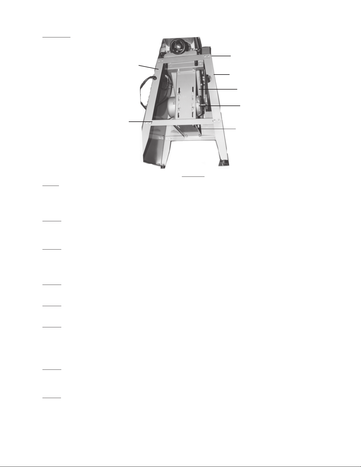
The Stand
Roof (1A)
Front Side Plate(16A)
Rear Side Plate (30A)
Upright Plate (4A)
Motor (29A)
Side Link Plate(19A)
Crossbeam Plate (18A)
Figure 1
Step 1) Attach the Front Side Plate (#16A) to both of the Side Link Plates (part #19A).
Insert two Screws (#17A) through Front Side Plate and through Side Link
Plate. Slide on W ashers (#7A) and Nut (#6A). Tighten into place. Repeat f or the other side
- see Figure 1.
Step 2) Attach the Rear Side Plate (#30A) to each of the Side Link Plates (#19A).
Tighten it into place with two Screws (#17A) and attach Washers (#7A) and Nuts (#6A)
on inside. Repeat f or other side-see Figure 1.
Step 3) Set the Crossbeam Plate (#18A) so that it sits on top of each of the Side Link
Plates (#19A). Insert two (2) Screws (#17A) through the Crossbeam Plate (#18A) and Side
Link Plate. Slide on W ashers (#7A) and Nuts (#6A). Tighten into place. Repeat for other
end of Crossbeam Plate- see Figure 1.
Step 4) Set the Roof (#1A) on top of the Side Plates. Insert two Screws (#17A) at each
corner. On the inside slide on Washer (#7A) and Nut (#6A). Secure in place-see Figure 1.
Step 5) Attach the foot Bolt (#22A) through the Chassis (#20A) and to the bottom of each corner.
From the top , slide on W asher (#7A) and tighten on Nut (#6A).
Step 6) Set the Jointer on the Stand with the Cutterhead Guard facing the F ront SidePlate (#16).
There are two holes for the Bolts (#68-Jointer Assembly) o v er the Right Protecting Plate (#8A)
and one hole for a Bolt (#68-Jointer Assembly) in the center of the Roof (#1A) abov e the Left
Protecting Plate (#26A). Slide the Bolt (#68-Jointer Assemb ly) through the flat Washer
(#67-Jointer Assembly) through the Roof (#1A) and into the Jointer .
Step 7) Attach the Right Tapping Fender (#23A) and the Left Tapping Fender (#27A) to the
Tapping Plate (#25A). Insert Lock W asher (#21A) with the head on the outside of the Stand.
Slide on W asher (#7A) and Nut (#6A). Tighten Tapping Fenders onto Plate-see Figure 2.
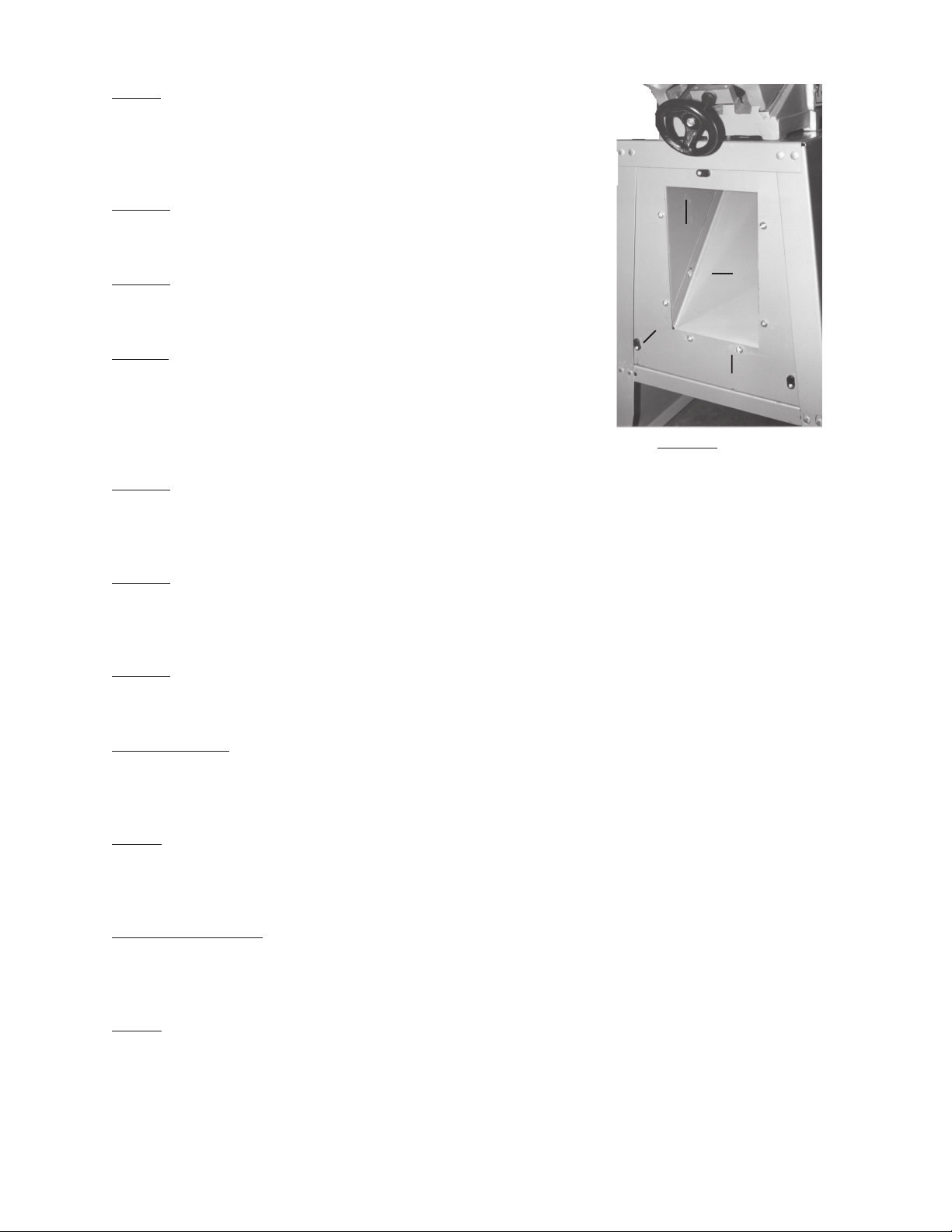
Step 8) Attach a Lock Plate (part #24A) to each corner hole and to the top hole in the Left Protecting
Plate (#26A). Mak e certain that the part of the Lock Plate with the wing is on the outside of
the Protecting Plate-see Figure 2.
#31849 Page 5
Page 6
Step 9) Attach the Tapping Plate (#25A) with Right and Left
Tapping Fenders (#23A & #27A) to the Left Protecting
Plate (#26A). Insert the Screws (#17A) with head on the
outside of the Plate. On the inside , slide on W asher
(#7A) and Nut (#6A)-see Figure 2.
Step 10) Attach the Reinforcing Plate (#3A) to the Roof ( #1A)
on the same side as the Left Protecting Plate
using Screws (#17A), Washers (#7A) and Nuts (#6A).
Left T apping Fender (#27)
Step 11) Attach the Upper Link Plate (#2A) to the Roof (#1A)
with Screw (#17A) inserted downward. Slide on
Washer (#7A) and tighten on Nut (#6A)-see Figure 1.
Step 12) Slide the Left Protecting Plate (#26A) on and tighten it
into place with six (6) Screws (#17A). F asten on
the inside with W ashers (#7A) and Nuts (#6A).
Make certain that the lips at the top of the
Tapping Plate (#25A) are positioned under the
Upper Link Plate (#2A) as in Figure 1.
Step 13) Attach the Motor (#29A) to the Upright Plate (#4A) making certain that the Screws
(#17A) are placed at least half way up the Plate (#4) on the side opposite the lips. You will
have to move the Motor (#29A) later when tensioning the Belt. Secure in position with
Washer (#7A) and Nut (#6A)-see Figure 1.
Step 14) Mount the Upright Plate (#4A) so that it is attached at the top to the Upper Link Plate (#2A)
and at the bottom to the Side Link Plate (#19A). Attach to the Upper Link Plate making sure
that the lips of the Tapping Plate (#25A) are sandwiched between the Upper Link Plate (#2A)
and the Upright Plate (#4A).
Step 15) Attach three (3) Lock Plates (#24A) to the Right Protecting Plate (#8A). Slide the Plate
onto the Frame and twist the Loc k Plates so that the Right Protecting Plate is securely in
position.
Lock Plate (#24A)
Left Protecting Plate (#26A)
Figure 2
T apping Plate (#25A)
Jointer Assembly
Each of the following part numbers, unless otherwise specified, are from the Jointer Parts List on page 14 and
the Jointer Assembly Diagram on page16.
Step 1) Attach the Belt Cover (#64) to the Stand (#69). Make certain that the Belt (#10) is
in place on the Center Head Pulley (#9). Insert Recessed Screw (#63) through
each foot of the Belt Cov er (#64). From underneath, attach Lock Washer (#65) and tighten
into place with Nut (#66).
Adjusting Belt Tension
Correct tension is indicated when there is approximately 1" deflection in the Belt (#10)
with slight finger pressure.
Step 1) Loosen the Nuts and Bolts on the Upright Plate (#4A-Stand Assembly). Mo v e the Motor up or
down along the Upright Plate until the correct tension is achieved. Tighten Nuts and Bolts
into place-see Figure 3.
#31849 Page 6
Page 7

Cutterhead Guard
Warning: Beware of sharp blade when installing the Cutterhead Guard.
Step 1) Inside of the Spring Knob (#37) there is a Spring (#36) which returns the Guard toits position
above the Cutterhead after a cut. To create tension in the Spring, turn the Spring Knob (#37)
before inserting the post. Insert the Postof the Cutterhead Guard (#32) down through the hole
in the Infeed Table (#33)-see Figure 4. When inserting the Post, mak e sure that the Spring
(#36) is engaged in the slot at the end of the Post. The tension on the Spring (#36) can
be changed by removing the Guard and turning the Spring Knob (#37).
Assembling Handle Wheels
Step 1) There is a Handle Wheel (#43) located on each side of the Base (#50). With Adjusting Pole
(#49) inserted into Base (#50), make certain Lock Block (#46) sits on top of the Adjusting Pole.
Insert Bolt (#40) into Washer (#41) and through Handle Wheel (#43). Screw into Lock Washer
(#44) and Lock Screw (#45).
Fence and Angle Scale Assembly
Step 1) Insert the Fence Plate (#18) through the hole in the Cross Slide Plate (#19). Insert Washer
(#25) and Nut (#26) onto Bolt (#27). Add Washer and slide Bolt (#27) through Plate (#18).
Attach the Handle Pole (#29) and Sock et (#30) o v er the Nut. Attach Cap (#31) and tighten
into place-see Figures 5, 6 and 7.
Figure 3 Figure 4
Jib
#31849 Page 7
Bolt (27)
Figure 5
Hex Screw (#24)
Washer (25)
Nut (26)
Handle Pole
(29)
Socket (30)
Figure 6
Page 8

Plate
Jib
Figure 7
Step 2) Flip the square jib so that its end sits against the flat part of the Plate (18)-see Figure 7.
Step 3) Using an Allen Wrench, attach this assemb ly to the Fence (#11) with the three Hex Screws
(#24)-see Figure 6.
Operation
When operating your Jointer , it will be helpful to ref er to the Parts List and Assembly Diagram on the last pages
of this manual.
Never force the tool or attachment to do the work of a larger industrial tool. It is designed to do the job better
and more safely at the rate for which it w as intended.
Use only wood boards.
Do not force feed y our work through the machine . Allow the Jointer to feed at the designated rate of f eed.
Note: This tool is specifically designed for the planing of lumber . Before working with any lumber ,
check for an y foreign materials such as nails, screws, or hard impurities. Also check for loose
knots in the wood. If not cleaned off these may cause damage to the blade or machine.
When feeding your lumber, use Push Blocks to feed the lumber , r ather than
using your hands.
Settings and Adjustments
Before adjustments are made, ensure that the machine is SWITCHED OFF AND UNPLUGGED. Also make
sure all locking handles and securing screws are fully tightened when adjustments are complete.
Raising and Lowering Tables
Step 1) For both the Inf eed Table (#33) and Out F eed Table (#1) loosen the Lock Scre w (#45) nearest
the Handle Wheel (#43). T urn the Handle Wheel until the Table is set at the proper height.
Once the table is set as desired, tighten down the Lock Scre w (#56).
#31849 Page 8
Page 9

Fence Adjustments
The Fence (part #11) is assembled to the front of the Infeed Table (#33). The Fence can be moved across the
Table and can be tilted 45 degrees right or left by using the Handle Pole (#29).
Step 1) To mov e the F ence (#11) across the Table, turn the Handle P ole (#29) to loosen. Slide the
Socket (#30) ov er the Nut (#26). Use the Socket (#30) to loosen the Nut (#26). Slide the
Table to its desired position. Tighten the Soc k et (#30) in place and tighten bac k down the
Handle.
Step 2) To tilt the Fence (#11), loosen the Handle Pole (#29). Slide the Sock et (#30) o v er the
Cap (#31). Loosen the Cap and tilt the F ence to the desired position. Tighten the Cap (#31)
into place and tighten back down the Handle P ole (#29)-see Figure 6.
Most Common Operations
Jointing cuts or edges as well as Planing are the two most common operations which can be done with your
Jointer. For Jointing, set the fence square with the table. Hold the best face of your work piece firmly against
the fence throughout the f eed.
Note: Do not perform jointing on material shorter than 10 “, narrower than 3/4”, or thinner than 1/2".
Planing is similar to jointing except that the workpiece is placed differently. The flat surface of the piece is
placed on the infeed table with the narrow edge of the piece against the fence. Mo v e the piece from the inf eed
table, acr0oss the cutterhead to the outf eed tab le . Always use the push b loc ks when planing. Never pass y our
hands directly over the cutterhead.
Grain Direction
Feeding with the grain is f eeding so that the kniv es tr a v el in the same direction as the slant of the
grain. Please see Figure belo w.
Figure 8 - Grain Direction
Grain patterns often have a “V” shape. The point of the “V” should point a w ay from the cutter head while
feeding.
Grain direction can also be determined by running your fingertips over the stock. The stock will be smoother
when your fingertips are moving with the grain.
Occasionally the grain direction reverses in the same piece of wood. For best planing results, it would be better
to cut the board in half so that each section can be planed with the grain.
Knife and Outfeed Table
The knives must be perfectly level with the outfeed table . Make certain that the Jointer is OFF and
that it is UNPLUGGED before making any adjustments.
Step 1) Loosen the Lock Lev er and lo wer the inf eed table b y pushing the Handle do wn.
Step 2) Remove the Cutterhead Guard.
Step 3) Place a steel straight edge on the outfeed table so that it also covers the cutterhead.
Carefully turn the cutterhead so that the knives are barely touching the straight edge.
#31849 Page 9
Page 10

Step 4) If the knife is not aligned at one or both sides, loosen Bolts (60) which hold the Knife Lock Bar
(61). Use a knife setting gauge (not included) to make sure that the knife at each end of the
cutter is the same height. Repeat for the next two (2) knives as is fitting. If the knives are set
to low, this will result in a curve in your wood. If the knives are too high, it may result in a
gouged cut in your work piece.
Adjusting Table Gibs
“Gibs” are adjusted at the factory and should not need adjusting. Adjustments should be made by a qualified
service technician. If adjustment is required, please follow the steps laid out below after unplugging the
electrical connection.
Step 1) Loosen all the gib adjusting screws, making sure that the Table Lock Screw (#45) is loose .
Step 2) Retighten the gib screws beginning with the lowest first and mo ving to the top gib. Push up
gently on the outside edge of the Table being adjusted.
Warning: Do not leave the scre ws too loose . It should take some effort to move the Table up or down.
Removing or Replacing Knives
Make certain that the Jointer is UNPLUGGED and OFF. Adjustments should be made m y a qualified service
technician. Be extremely careful when handling the knives! Make certain that the Bars are free of dirt and
debris.
Step 1) Move the F ence (#11) to the rear of the Jointer and remove the Cutterhead Guard.
Step 2) With a wrench, loosen the four (4) Screws (#12) in each knife slot. Remov e each Knife (#62)
and the Knife Lock Bars (#61).
Step 3) Replace the Knives (#62) in the groove so that the rear edge of the bevel is 1/16” from the
surface of the Cutterhead.
Step 4) Slide the Lock Bar (#61) into place. Tighten down the Scre ws (#12) in each slot.
Warning! Knife edges are very sharp. Be very careful when moving knives. Refer to Operator Safety
Instructions at the beginning of this manual.
Step 5) The surface of the Cutterhead and the blade m ust be parallel, as w ell as the b lade to the Bar.
All three should be parallel to each other.
Step 6) Correct adjustment will ensure that the cutting edge of the knife e xtends out at
.060" from the cutterhead diameter.
Step 7) Carefully turn the cutterhead, until its round side is showing on top. Place a .060" feeler
gauge on the cutterhead. With a straight edge on the rear table adjust the height of the rear
table to .060".
#31849 Page 10
REV 02/05
Page 11
Step 8) Secure the rear table in position and remove the feeler gauge.
Step 9) Lower the infeed table and place a straight edge on the outfeed table so that it
extends out ov er the cutterhead.
Step 10) Turn the cutterhead by hand until the knife is at its highest point at each end of the cutterhead.
Using the wrench, turn the screw clockwise until the knife just touches the straight edge on
each end and at the center. Once the knife is fully adjusted, again tighten the four loc king
screws.
Sharpening the Knives
Step 1) Use a fine grade Carborundum stone. Cover the bottom portion of the stone with
paper. The top portion will touch the knife, and the paper will k eep the stone from
scratching the table.
Step 2) Lay the stone on the inf eed tab le . Lower the table and turn the cutterhead until the stone lies
flat on the edge of the knife. Sharpen the beveled edge of the knife b y sliding the stone bac k
and forth across the table. Repeat f or each additional knif e .
Wiring the Jointer-On and OFF
Step 1) Insert the Switch Box through the hole in the Stand (#69).
Step 2) Insert the wires through the hole in the Switch Box-
see Figure 9.
Outlet
Switch Box
Figure 9
Step 3) The cord from the Motor (#29A-Stand Assembly) contains three (3) different colored wires;
White, Green and Black. The White wire from the Motor (#29A) is attached to the wiring bo x on
the bottom lower left.
Step 4) The Black Wire from the Motor is attached to the bo x at the bottom right. The green from the
Motor is attached to the ground.
Step 5) The Electrical Cord has three different colored wires; Green, White and Black.
The white wire is to be attached to the box at the top left. The Black is to be
attached to the top right. The g reen wire goes to the ground.
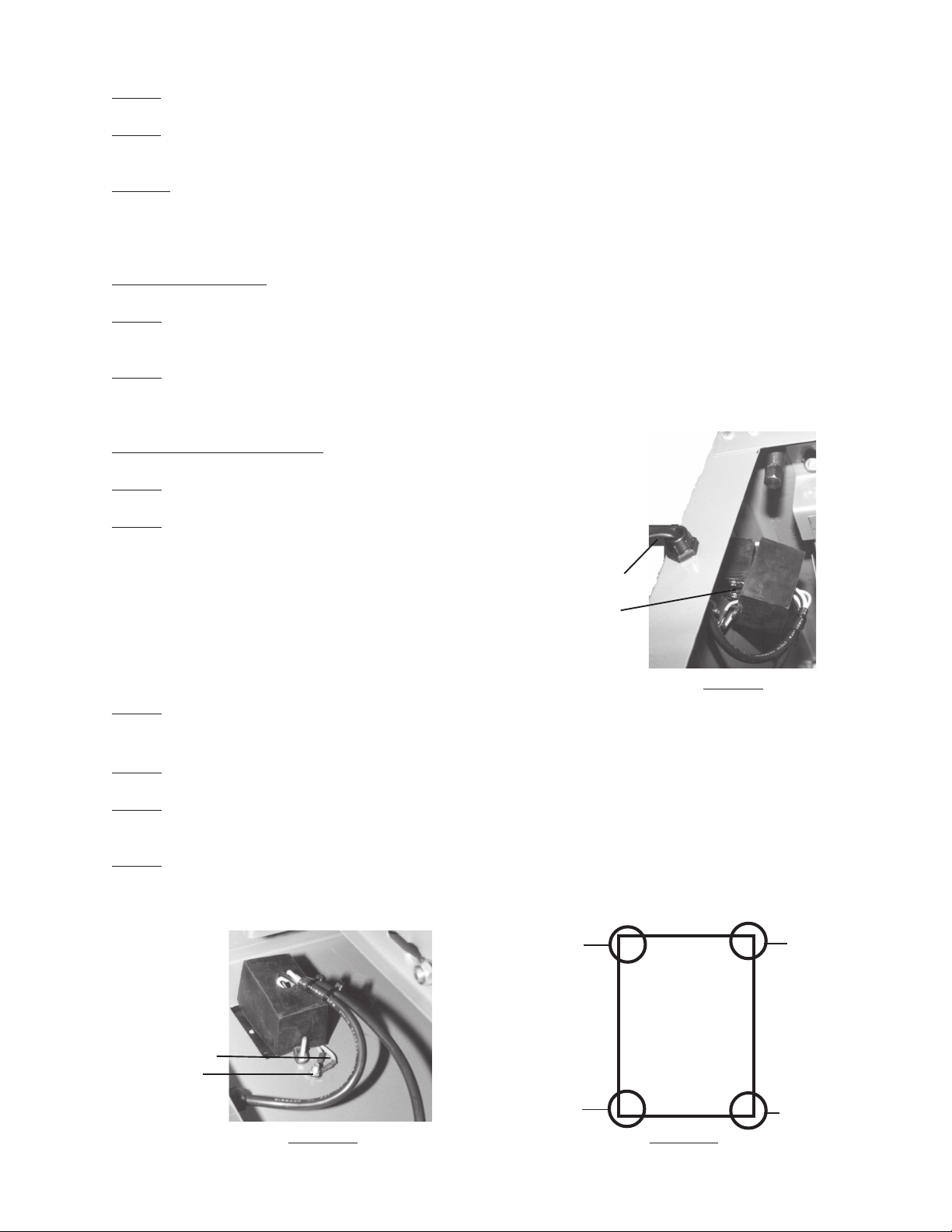
Step 6) The ground is the lower screw as sho wn in Figure 10 . The low er scre w is inserted through the
Jointer and is tightened into place by sliding on a Lock Washer and then a Nut. Do not tighten
into place until both green wires are attached to the ground-see Figure 10 and 12.
White from Outlet
Black
From Cord
Green Wires
Ground
White from Motor
Figure 10 Figure 11
#31849 Page 11
Black F rom Motor
Page 12

Black to corners
White to corners
Green to Ground
Turning the Jointer ON and OFF
Figure 12
Step 1) To turn the Jointer ON, press down on the green button on top.
Step 2) To turn OFF the Jointer, press down the red b utton on the bottom.
IF THERE IS ANY QUESTION ABOUT A CONDITION BEING SAFE OR UNSAFE, DO NOT OPERATE THE TOOL.
After Operation-Maintenance
CLEANING: Regularly clean the work surface with a dry brush or clean cloth. K eep machined
parts of the Jointer lightly greased. Prev ent w ood, dust and debris from accumulating.
STORA GE: Child-proof the machine and work area. Make sure to use padlocks and master switches
IF THERE IS ANY QUESTION ABOUT A CONDITION BEING SAFE OR UNSAFE, DO NOT OPERATE THE TOOL.
PLEASE READ THE FOLLO WING CAREFULL Y
THE MANUF ACTURER AND/OR DISTRIBUT OR HAS PRO VIDED THE PARTS DIAGRAM IN THIS MANU AL AS
A REFERENCE TOOL ONLY. NEITHER THE MANUFACTURER NOR DISTRIBUTOR MAKES ANY
REPRESENT ATION OR WARRANTY OF ANY KIND TO THE BUYER THAT HE OR SHE IS QUALIFIED T O MAKE
ANY REPAIRS TO THE PR ODUCT OR THAT HE OR SHE IS QU ALIFIED TO REPLA CE ANY PARTS OF THE
PRODUCT . IN F ACT, THE MANUF ACTURER AND/OR DISTRIBUT OR EXPRESSLY STATES THA T ALL REPAIRS
AND PARTS REPLA CEMENTS SHOULD BE UNDER TAKEN BY CERTIFIED AND LICENSED TECHNICIANS
AND NOT BY THE BUYER. THE BUYER ASSUMES ALL RISK AND LIABILITY ARISING OUT OF HIS OR HER
REP AIRS TO THE ORIGINAL PRODUCT OR REPLACEMENT PARTS THERET O, OR ARISING OUT OF HIS OR
HER INST ALLATION OF REPLACEMENT P ARTS THERETO .
#31849 Page 12
Page 13

Unpacking
UNPACK AND CHECK CONTENTS
When unpacking your Jointer with Stand check to mak e sure the following parts are included. If any parts are
missing or broken, please call HARBOR FREIGHT TOOLS at 1-800-444-3353.
Parts List - Stand Assembly
Part # Description Quantity Part # Description Quantity
1A Roof 1 17A Head Square Root Screw 32
2A Upper Link Plate 1 18A Crossbeam Plate 1
3A Reinforce Plate 1 19A Side Link Plate 2
4A Upright Plate 1 20A Chassis 4
5A Bolt M8 X25 4 21A Lock Washer 4
6A Nut 50 22A Bolt 1
7A Washer 50 23A Right Tapping Fender 6
8A Right Protect Plate 1 24A Lock Plate 1
9A Nut 2 25A Tapping Plate 1
10A Screw M4 x 25 2 26A Left Protecting Plate 1
11A Screw M5 X 8 1 27A Left Tapping F ender 1
12A Washer 1 28A Motor Pulley 1
13A Nut 1 29A Motor 1
14A Lock clip 1 30A Rear Side Plate 1
15A Cabl e 1 31A Button head Cap Scre w 10
16A F ront Side Plate 1
Note: Some parts listed and shown (pages 13 through 16) are for illustration
purposes only and are not available individually as replacement parts.
#31849 Page 13
Page 14

Parts List - Jointer Assembly
Part # Description Quantity Part # Description Quantity
1 Outfeed T able 1 36 Spring 1
2 Bearing Housing 1 37 Spring Knob 1
3 Ball bearing 1 38 Retainer 1
4 Cutter Head Assembly 1 39 Recessed Screw 3
5 Key 1 40 Belt 2
6 Ball Bearing 1 41 Washer 2
7 Bearing Housing 1 42 P in 2
8 Set Screw M6 X 12 2 43 Handle Wheel 2
9 Cutter Head Pulley 1 44 Lock Washer 2
10 Belt 1 45 Loc k Screw 2
11 F ence 1 4 6 Lock Block 2
12 Set Screw M6 X 10 1 47 Flat Washer 4
13 Roll Pin 1 48 He x Screw 4
14 Set Screw M 6 X 10 1 49 Adjusting Pole 2
15 Set Screw M6 X 10 1 50 Base 1
16 Bolt 6 X 40 3 51 Nut 2
17 Nut 3 52 Lock Washer 2
18 Plate 1 53 Fault Washer 2
19 Cross Slide Plate 1 54 Screw 2
20 Stop Block 1 55 Depth Scale 1
21 Pointer Rod 1 56 Lock Screw 2
22 Fence Segment 1 57 Bolt 4
23 Tilt Angle Seat 1 58 Nut 4
24 Hex Screw 3 5 9 Gib 2
25 Washer 3 60 Bolt 12
26 Nut 1 61 Knife Lock Bar 3
27 Bolt 1 62 Knives 3
28 Handle Ball 1 63 Recessed Screw M 8 X 12 2
29 Handle Pole 1 64 Belt Cover 1
30 Socket 1 65 Flat Washer 2
31 Cap 1 66 Nut 2
32 Cutter Guard 1 67 Flat W asher 3
33 Infeed T able 1 68 Bolt 3
34 Retainer W asher 1 69 Stand (See Stand Assy .) 1
35 Depth Scale 1
#31849 Page 14
REV 10/02
Page 15

Stand Assembly Diagram
Each of the Part Numbers below correspond to the Stand Assembly and has the suffix “A” - see Parts List on
Page 13.
#31849 Page 15
Page 16
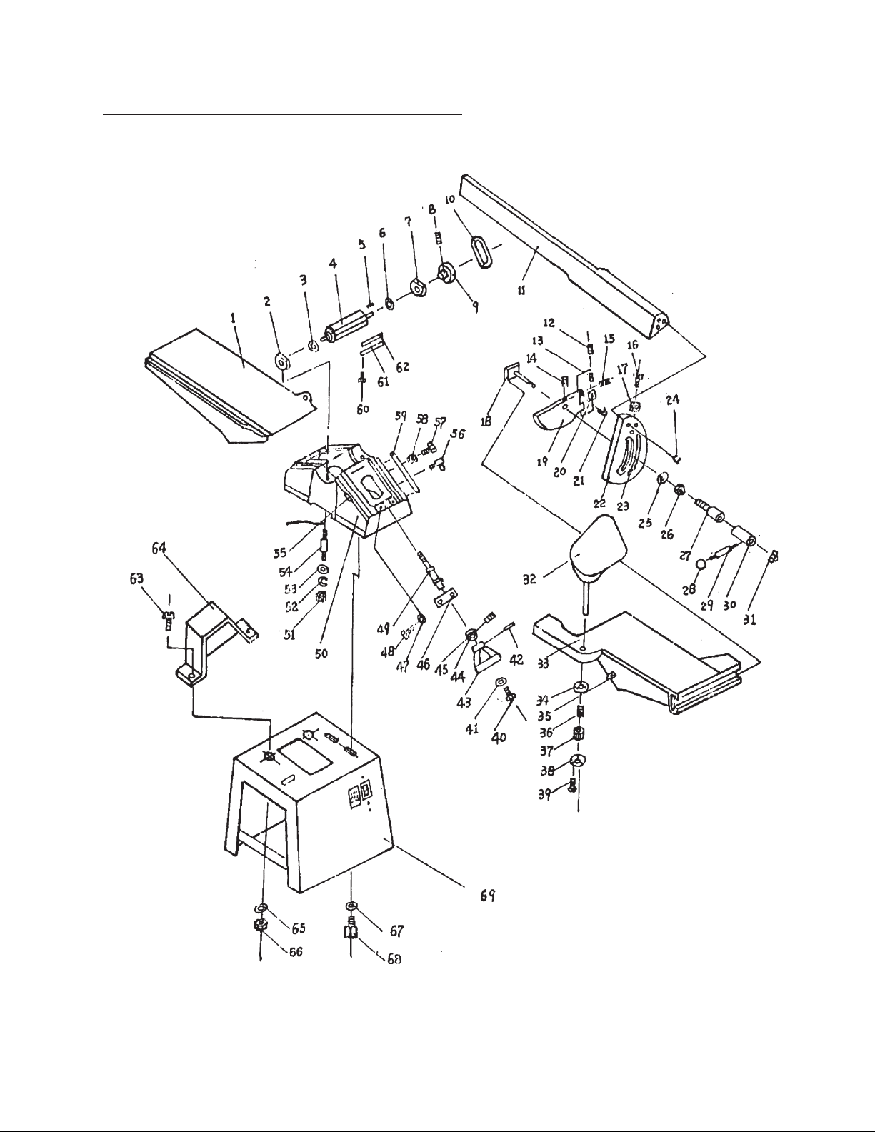
Jointer Assembly Diagram - See Parts List on Page 14
#31849 Page 16
Page 17

Wiring Diagram
White
White
Black
Black
#31849 Page 17
 Loading...