

Page 1
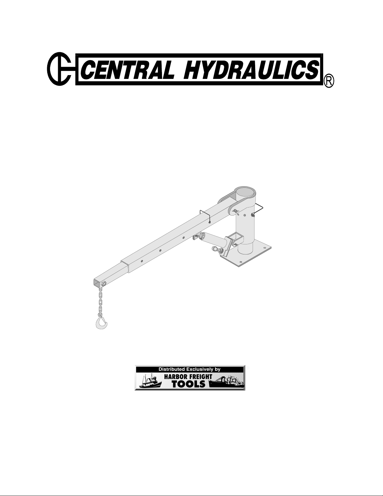
PICK UP TRUCK LIFT
®
ASSEMBLY & OPERATING INSTRUCTIONS
Model 1647
SPECIFICATIONS:
Maximum capacity: 1/2 Ton
Boom length: 33-1/2” to 53” (4 positions)
Weight: 77 Lbs.
Chain is 7-1/2” L, 3/8” Diameter
5/8” latch-type
Due to continuing improvements, actual product may differ slight from the product described herein.
3491 Mission Oaks Blvd. / Camarillo, CA 93011
Copyright © 1997 by Harbor Freight Tools®. All rights reserved.
No portion of this manual or any artwork contained herein may be reproduced in any
shape or form without the express written consent of Central Purchasing Incorporated.
For technical questions and replacement parts, please call 1-800-444-3353.
Revised Cover Page 12/05
Page 2

SAVE THIS MANUAL
You will need this manual for the safety instructions, assembly
and operating instructions and parts list. Put it in a safe, dry
place for future reference. Keep your invoice with this
manual. Write the invoice number on the inside
front cover.
READ ALL INSTRUCTIONS
BEFORE ASSEMBLING OR
OPERATING THE PICK UP
TRUCK LIFT.
SAFETY WARNINGS & CAUTIONS
1. KEEP WORK AREA CLEAN. Cluttered areas invite injuries.
2. KEEP CHILDREN AWAY. All children should be kept away from the work area. Don’t
let them handle tool.
3. DO NOT ASSEMBLE OR OPERATE THIS TOOL IF UNDER THE INFLUENCE OF
ALCOHOL OR DRUGS. Read warning labels on prescriptions to determine if your
judgment or reflexes are impaired while taking drugs. If there is any doubt, do not attempt to assemble or operate.
4. ALWAYS SET PARKING BRAKE AND BLOCK TIRES WHEN USING THE PICK UP
TRUCK LIFT. Vehicles with automatic transmissions should be left in “park”. Manual
transmissions should be left in gear. Never attempt to lift something while the vehicle is
moving.
5. AVOID ANY MOVING PARTS WHILE USING THE PICK UP TRUCK LIFT. While
lifting, keep fingers and hands away from moving parts.
6. USE EYE PROTECTION. Wear ANSI approved impact safety goggles. Goggles are
available from Harbor Freight Tools.
7. DRESS SAFELY. Protective gloves and non-skid footwear or safety shoes are recommended when working with and operating the Pick Up Truck Lift. Don’t wear loose
clothing or jewelry. They can get caught in moving parts. Also, wear a protective hair
covering to prevent long hair from getting caught in the Pick Up Truck Lift.
8. DON’T OVERREACH. Keep proper footing and balance at all times.
9. STAY ALERT. Watch what you are doing. Use common sense. Do not operate any tool
when you are tired.
10. 1000 POUND LIMIT. Do not operate the hydraulic pump beyond rated capacity.
11. REPLACEMENT PARTS AND ACCESSORIES. When servicing, use only identical
replacement parts. Only use accessories intended for use with the Pick Up Truck Lift.
Approved accessories and replacement parts are available from Harbor Freight Tools.
12. STORE IDLE EQUIPMENT. When not in use, the Pick Up Truck Lift should be stored in
its box and in a dry location to reduce rust. For safety, store the Pick Up Truck Lift in a
locked cabinet, out of reach of children.
Pg. 2 -- SKU 1647
Page 3

UNPACKING
When unpacking your Pick Up Truck Lift, check to make sure the following parts are included. If
any parts are missing or broken, please call Harbor Freight Tools at the number on the cover of this
manual.
Item # Description Qty Item # Description Qty
1 Base 1 17 Bolt 1
2 Post 1 18 Medium Pin 1
3 Grease Fitting 1 19 Small Pin 1
4 Boom 1 20 Large Lock Pin 1
5 Large Pin 1 21 Jack Handle 1
6 Cotter Pin 3 22 Bolt 5
7 Extendible Boom 1 23 Washer 5
8 Small Lock Pin 1 24 Lock Washer 5
12 Pump Unit * 1 25 Nut 5
13 Pump Release Valve 1 26 Steel Angle 2
14 Jack Support 1 27 Hook and Chain 1
15 Washer 1 28 Bolt 1
16 Spring Washer 1 29 Nut 1
* Includes parts #13-17.
GENERAL
Your Pick Up Truck Lift has four extension settings for the EXTENDIBLE BOOM (#7). Each of
these extension settings has a weight limit that is clearly marked on the BOOM (#4). Do not
exceed these weight limits as it may cause damage to the PICK UP TRUCK LIFT and\or cause
bodily harm.
Prior to use, liberally grease the unit using the GREASE FITTING (#3) located on the BASE (#1).
Swivel the BASE on the POST (#2) 360º while greasing to ensure optimum lubrication.
Warning: When installing the Pick Up Truck Lift, please note that
the Base (#1) must be securely bolted to the frame of the truck;
bolting the truck lift to the bed of the truck wil not provide the
necessary support needed.
Pg. 3 -- SKU 1647 REV 05/01
Page 4

ASSEMBLY
Step 1: Slide the POST (#2) onto the BASE (#1) and attach using the LARGE LOCK PIN
(#20) as shown in Figure 1.
Note:
If the bed and side panels of the truck will not get in the way during assembly, attach
the base to the truck’s frame first as described in step 8.
Figure 1 — Post to Base Assembly
Step 2: Attach the PUMP UNIT (#12) to the lower POST bracket using the MEDIUM PIN (#18)
as shown in Figure 2. Secure the MEDIUM PIN (#18) with a COTTER PIN (#6).
Figure 2 — Attaching the Pump Unit
Pg. 4 -- SKU 1647 REV 05/01
Page 5

Step 3: Attach the rear end of the BOOM (#4), with its bracket facing down, to the upper
POST bracket using the LARGE PIN (#5) and secure it with a COTTER PIN. See
Figure 3.
Step 4: Connect the PUMP UNIT plunger to the BOOM bracket using the SMALL PIN (#19).
Figure 3 — Boom Assembly
Step 5: Slide the EXTENDIBLE BOOM (#7) into the BOOM so that the end with the oval hole
is facing out and the oval hole is facing down (see Figure 4). Attach it at one of the
extension points using the SMALL LOCK PIN (#8).
Pg. 5 -- SKU 1647
Figure 4 — Extendible Boom Assembly
Page 6

Step 6: Connect the HOOK AND CHAIN (#27) to the end of the EXTENDIBLE BOOM by
putting the end link of chain through the oval hole and bolting it in place using its NUT
(#29) and BOLT (#28).Step 6: Connect the HOOK AND CHAIN (#27) to the end of
the EXTENDIBLE BOOM by putting the end link of chain through the oval hole and
bolting it in place using its NUT (#29) and BOLT (#28).
Note:
Nut #29 has a threadless shoulder.
Step 7: Attach the GREASE FITTING (#3) to the POST as shown in Figure (6).
Figure 6 — Installing the Grease Fitting
Pg. 6 -- SKU 1647
Page 7

Step 8: Attach the unit to the desired position by bolting the BASE down using the two STEEL
ANGLES (#26) as backing plates (see Figure 7). On most trucks a desirable position
is just behind the wheel well so that the BOOM may be stored over the wheel well.
Figure 7 — Installing the Truck Lift
Warning: When installing the Pick Up Truck Lift, please note that
the Base (#1) must be securely bolted to the frame of the truck;
bolting the truck lift to the bed of the truck wil not provide the
necessary support needed.
Pg. 7 -- SKU 1647 REV 05/01
Page 8

OPERATION
Step 1: Release the LARGE LOCK PIN (#20) located on the body of the POST (#2) and swivel
the POST so that the BOOM (#4) is pointing towards the object to be lifted.
Step 2: Position the HOOK AND CHAIN (#27) over the article to be moved by adjusting and
locking the EXTENDIBLE BOOM (#7) in place using its SMALL LOCK PIN (#8). Do
not exceed the weight limits marked on the side of the boom.
Figure 8 — Operating the Pickup Truck Lift
Step 3: Hook around the article so that its weight is centered.
Step 4: Place the slotted end of the PUMP HANDLE (#21) over the PUMP RELEASE VALVE
(#13) and close it by turning it in a clockwise direction.
Step 5: Insert the PUMP HANDLE into its connector and lift the BOOM by pumping the handle
in an up and down motion.
Step 6: When the article has been lifted to the desired height, it may be moved over the truck
bed by slowly swiveling the BASE (#1) on its POST until the object is directly over the
truck bed. Do not attempt to extend the BOOM further while the object is still Attached. If the object needs to be moved further; lower it, adjust the BOOM, and
re-lift it.
Step 7: Lower the object onto the truck bed by using the PUMP HANDLE to slowly turn the
PUMP RELEASE VALVE in a counterclockwise direction.
Pg. 8 -- SKU 1647
Page 9

PARTS LIST
Item # Description Qty Item # Description Qty
1 Base 1 17 Bolt 1
2 Post 1 18 Medium Pin 1
3 Grease Fitting 1 19 Small Pin 1
4 Boom 1 20 Large Lock Pin 1
5 Large Pin 1 21 Jack Handle 1
6 Cotter Pin 3 22 Bolt 5
7 Extendible Boom 1 23 Washer 5
8 Small Lock Pin 1 24 Lock Washer 5
12 Pump Unit * 1 25 Nut 5
13 Pump Release Valve 1 26 Steel Angle 2
14 Jack Support 1 27 Hook and Chain 1
15 Washer 1 28 Bolt 1
16 Spring Washer 1 29 Nut 1
Pg. 9 -- SKU 1647
 Loading...