

Page 1
OFF ROAD TRUCK LIGHT SYSTEM
®
Model 03029
3491 Mission Oaks Blvd., Camarillo, CA 93011
Visit our Web site at http//www.harborfreight.com
Copyright© 2003 by Harbor Freight Tools®. All rights reserved. No portion of this
manual or any artwork contained herein may be reproduced in any shape or form
without the express written consent of Harbor Freight Tools.
For technical questions, please call 1-800-444-3353.
SAVE THIS INSTRUCTION MANUAL
You will need this Instruction Manual for the safety warnings and precautions, assembly/ inspection/maintenance information, and assembly diagram. Keep your invoice with this Instruction
Manual. Write the invoice number on the front page. Keep this Instruction Manual and invoice in
a safe and dry place for future reference.
GENERAL SAFETY WARNINGS AND PRECAUTIONS
1. Use eye protection. Wear ANSI approved safety impact eye goggles when assembling this product.
ANSI approved safety impact eye goggles are available from Harbor Freight Tools.
2. Use the right tool or attachment for the job. There are certain applications for which this product
was designed. Do not modify this product, and do not use this product for a purpose for which it was
not intended.
3. Replacement parts and accessories: When servicing, use only identical replacement parts. Only
use accessories intended for use with this product.
4. The Off Road Truck Light System is for OFF ROAD use only. Check with local and/or State
regulations regarding installation and use of this product on your vehicle.
5. WARNING! Vehicles equipped with airbags may have the sensors located inside the front bumper.
Make sure to consult the vehicle owner’s manual to determine the location of the airbag sensors. To
avoid damaging the sensors if they are located in the front bumper, do not drill holes in the bumper.
6. The 100 Watt Halogen Lamps become extremely hot under continuous use. Do not touch the
Lamps for at least 30 minutes after turning off the Lamps.
7. Turn off the Off Road Light System, disconnect its Power Cord from its 12 Volt DC Battery, and allow
its Halogen Lamps to completely cool down prior to performing any inspection, maintenance, or
cleaning on the unit.
8. WARNING! The warnings, precautions, and instructions discussed in this manual cannot cover all
possible conditions and situations that may occur. The operator must understand that common sense
and caution are factors which cannot be built into this product, but must be supplied by the operator.
MANUAL REV 04/05
Page 2
UNPACKING
When unpacking, check to make sure all the parts shown are included. If any parts are missing or
broken, please call Harbor Freight Tools at the number shown on the cover of this manual as soon as possible.
ASSEMBLY INSTRUCTIONS
1. To avoid accidental short circuits, disconnect the negative (-) terminal of the vehicle battery prior to
assembling the Off Road Truck Light System.
2. NOTE: The Halogen Lamps may be mounted above or below the front bumper. Make sure the desired
mounting location does not obstruct the vehicle’s headlights or turn signals.
3. Place the Halogen Lamps on the bumper, and mark the desired mounting locations at an equal
distance from the center of the bumper.
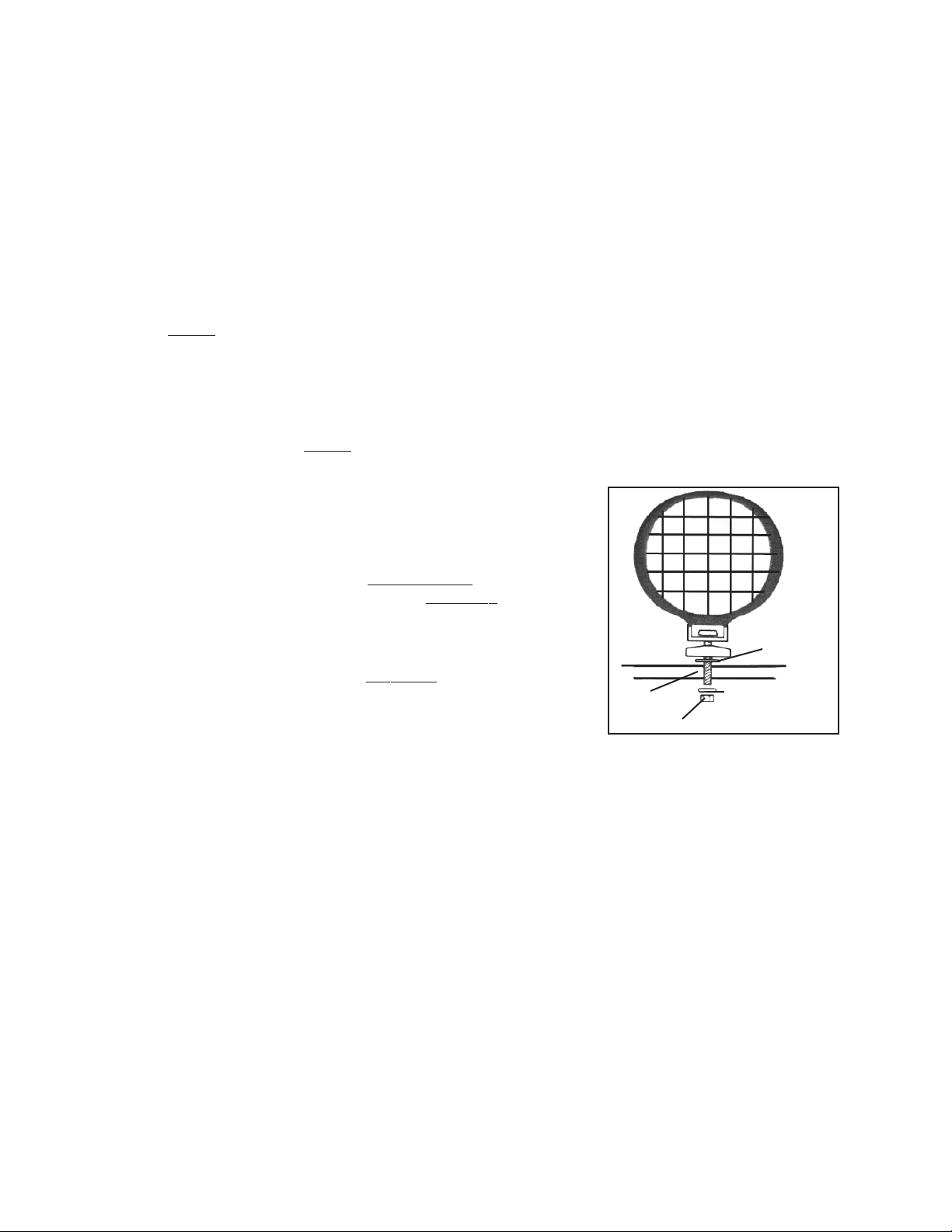
4. Where pre-marked, drill a 3/8” hole through the bumper. Then, mount the Halogen Lamps using the
hardware provided. NOTE: Make sure no electrical wires or cables are in the way of the drilling path.
(See Figure A.)
5. Mount the Light Switch in a location that is within easy reach
(i.e., dashboard, console). With the Light Switch in the desired
position, mark the holes for drilling and drill two 1/16” holes.
Then, mount the Light Switch with the Screws provided.
6. Connect the Red Wire of the passenger side Lamp to the 4 ft.
Red Extension Wire. (See Figure B, next page.)
7. Connect the 4 ft. Red Extension Wire to the “Y” Connector of
the 12 ft. Red Extension Wire. (See Figure B.)
8. Connect the Red Wire of the driver side Lamp to the “Y” Con-
nector of the 12 ft. Red Extension Wire. (See Figure B.)
9. Connect the Black Ground Wire from each Lamp (using the
Screws provided) to the chassis of the vehicle or any other
grounded metal surface. (See Figure B.)
10. Route the 12 ft. Red Extension Wire along the vehicle’s existing wiring, on the side of the engine
compartment, through the existing hole in the firewall, to the previously installed Light Switch. (See
Figure B.)
11. Connect the 12 ft. Red Extension Wire to the Light Switch terminal #2. (See Figure B.)
12. Connect the Black Ground Wire to the Light Switch terminal #4 and the other end of the Black
Ground Wire (using the Screws provided) to the chassis or any other grounded metal surface.
(See Figure B.)
13. Connect one end of the Blue Power (Hot) Wire to the Light Switch terminal #1 and the other end of the
Blue Power (Hot) Wire to a (+) 12 Volt power source at the fuse box or the (+) terminal of the vehicle’s
battery. (See Figure B.)
14. Use plastic tie-strips (not provided) to secure the wiring throughout the vehicle. Make sure to avoid
hot areas and moving parts. Also, tape all connections using electrical tape (not provided). Protect
the wiring from sharp edges with tape or grommets.
3/8”
HOLE
NUT
LOCK WASHER
FLAT
WASHER
FIGURE A
15. Once assembly is complete, reconnect the (-) terminal of the vehicle’s battery and turn on the Light
Switch to ensure the Off Road Truck Light System is properly operating.
Page 2SKU 03029 For technical questions, please call 1-800-444-3353.
Page 3

BLACK
GROUND
WIRE
LIGHT SWITCH
4
2
1
12 FT. RED EXTENSION WIRE
PASSENGER SIDE
BLACK
GROUND
WIRES
FUSE
(20 AMP)
DRIVER SIDE
BLUE
POWER (HOT)
WIRE
TO FUSE BOX
OR
(+) BATTERY
TERMINAL
“Y”
CONNECTOR
FIGURE B
4 FT. RED EXTENSION WIRE
INSPECTION AND MAINTENANCE
1. WARNING! Always unplug the Off Road Truck Light System from its 12 Volt DC power source and
allow the unit to completely cool down before performing any inspection or maintenance.
2. BEFORE EACH USE, inspect the general condition of the Off Road Truck Light System. Check for
misalignment or binding of moving parts, cracked or broken parts, damaged Wiring, damaged Lens/
Lens Guard, and any other condition that may affect its safe operation. If a problem occurs with the
Lights, have the problem corrected before further use. Do not use damaged equipment.
3. TO CHANGE THE 100 WATT HALOGEN BULB, open the Lens Guard and remove the Lens. Using
gloves or a soft cloth, gently press the Bulb to one side of the Socket and remove the opposite end.
Reverse this procedure to install a new Bulb. NOTE: Do not touch the new Bulb with your fingers, as
oil in your skin will damage to the Bulb if not cleaned off before use.
PLEASE READ THE FOLLOWING CAREFULLY
THE MANUFACTURER AND/OR DISTRIBUTOR HAS PROVIDED THE DIAGRAMS IN THIS MANUAL AS A REFERENCE TOOL ONLY. NEITHER THE MANUFACTURER OR DISTRIBUTOR MAKES ANY REPRESENTATION OR
WARRANTY OF ANY KIND TO THE BUYER THAT HE OR SHE IS QUALIFIED TO MAKE ANY REPAIRS TO THE
PRODUCT, OR THAT HE OR SHE IS QUALIFIED TO REPLACE ANY PARTS OF THE PRODUCT. IN FACT, THE
MANUFACTURER AND/OR DISTRIBUTOR EXPRESSLY STATES THAT ALL REPAIRS AND PARTS REPLACEMENTS
SHOULD BE UNDERTAKEN BY CERTIFIED AND LICENSED TECHNICIANS, AND NOT BY THE BUYER. THE
BUYER ASSUMES ALL RISK AND LIABILITY ARISING OUT OF HIS OR HER REPAIRS TO THE ORIGINAL PRODUCT
OR REPLACEMENT PARTS THERETO, OR ARISING OUT OF HIS OR HER INSTALLATION OF REPLACEMENT
PARTS THERETO.
Page 3SKU 03029 For technical questions, please call 1-800-444-3353.
 Loading...