

Page 1

Lithium power BMS manual
—— GTBMS005A-MC8
Harbin Guantuo Power Equipment Co.,LTD.
2009-7-22
Page 2

GuanTuo Power
CONTENT
1 PRODUCT INTRO AND SYSTEM SETTING ...................................................................2
1.1
1.2
1.3
2 CONNECTION WITH CHARGERS AND MOTOR CONTROLLER .......................8
2.1
2.2 S
3 NOTICE AND CONTACT...................................................................................................11
3.1 N
3.2 C
COMPOSEITION AND FUNCTION OF PRODUCTS ........................................................................ 2
MAIN TECHNICAL PARAMETERS ............................................................................................. 3
SYSTEM SETTING..................................................................................................................... 4
INTERFACE AND CONNECTION................................................................................................. 8
YSTEM WORKING PRINCIPLE ................................................................................................. 9
OTICE ................................................................................................................................. 11
ONTACT US ......................................................................................................................... 11
1
Page 3

GuanTuo Power
1 Product intro and system setting
1.1 composeition and function of products
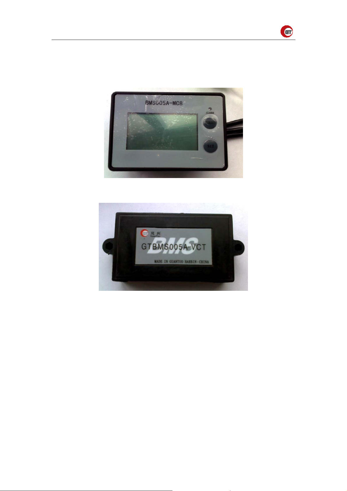
GTBMS 005A battery management is made up of a GTBMS 005A-MC8 management
host、 two GTBMS005-VCT voltage/current/temperature module, can measuring all
voltage of single batteries, total current of pile, environment temperature.. Detailed
performance as follows:
1.
Management host consists of black and white LCD and management calculator, first
page displays of battery group total voltage and total current、max voltage and battery
number、min voltage and battery number; second page displays capacity(adds while
is charging, subtract while is discharging, save while power cut, clear )、consume
Walt-hour、,max temperature of all measuring points and min temperature; press key
display every battery voltage;
2.
Sampling module adopts master-slave mode. Master sampling module manages ten
batteries、 one current and one temperature, slave sampling module manages ten
batteries and one temperature.
3.
Master sampling module provides one sampling current, current sensor is current hall
sensor.
4.
The number of batteries that is managed by sampling module can be set from 1~N
(N<<10) through management host, connection mode adopts N+1.
5.
Management host has two alarm interfaces, switch of voltage upper limit、aural and
visual alarm, high temperature switch、aural and visual alarm, switch of high
temperature、aural and visual alarm, switch of over current、aural and visual alarm.
Max voltage alarm and high temperature alarm share the same group interface,
voltage lower limit alarm and over current alarm share the same group interface.
6.
Host has two keys: “first” and “set”. Select “first”, screen displays first page
information, press “set” key you can search all information except that of the first
page; under the first page state, keep pressing “first ” key for five seconds to get into
parameter set menu; under the first page state, keep pressing “set” key for five
seconds to get into running parameter set menu. Get into the second page, keep
pressing “first” key for five seconds to clear capacity value ,keep pressing “set” key
2
Page 4
GuanTuo Power
for five seconds to clear watt value ; When the system gets into alarm state, it will
provide flashing light、buzzer and a group of relay contacts to alarm. System running
parameters include: the number of batteries that each sampling module manages、
voltage upper /lower limit、voltage cut lower limit、temperature cut upper limit.etc.
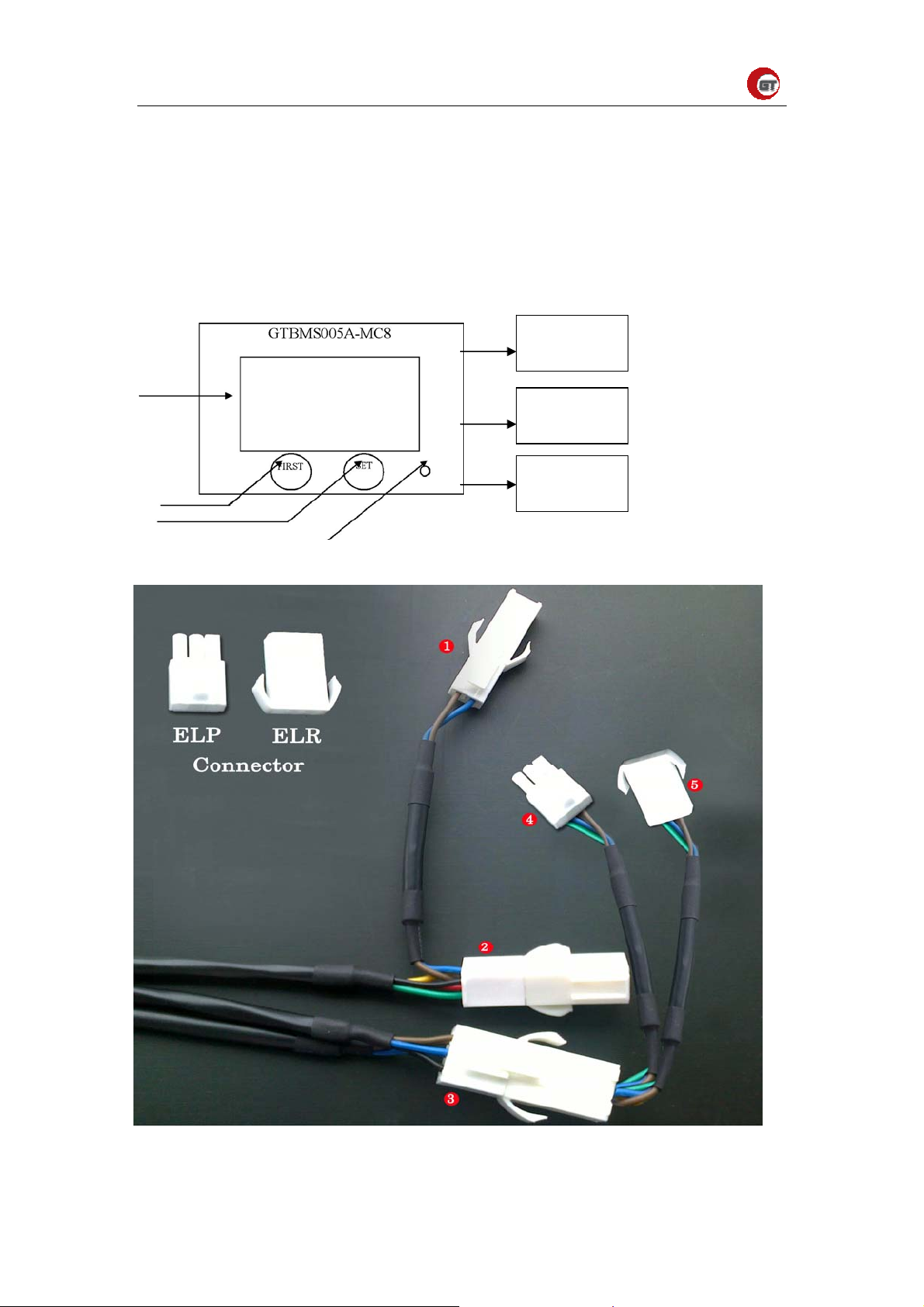
Figure1-1-1 Manage host
Figure1-1-2 module
1.2 main Technical parameters
·voltage measuring range ……………………………………… 0~+5V
·
voltage measuring accuracy ……………………………………… ±(0.3%RD+0.2%FS)
·voltage display accuracy ……………………………………… 1mV
·
temperature measuring range ……………………………………… -10~+85℃
·
temperature measuring accuracy ……………………………………… ±1℃
·minimum sample cycle(voltage) ……………………………………… 0.5s
·
accumulated capacity cycle ……………………………………… 0.5s
·
capacity display accuracy……………………………………… 1Ah
·
capacity measuring upper limit……………………………………… ≤999Ah
3
Page 5
GuanTuo Power
·alarm contacts index
Maximum switch voltage ……………………………………… 30Vdc
Maximum switch current ……………………………………… 1A
·
LCD
Black and white screen,
white back lighting Display region
………………………………47mm x 26mm
1.3 system setting
VCT sampling module set
Address set: When the battery number is no more than ten, only one VCT module is
enough, and this module is master module, master module can manage less than ten
batteries, and provide a loop of temperature and current.
.When the number of batteries is more than ten, the system will need two VCT modules,
one is master module (not need to be set) and another is set as slave module. Master
module can manage less than ten batteries, and provide a loop of temperature and current.
Slave module can manage no more than ten batteries, and provide a loop of temperature。
There cannot be two slave sampling modules in the system at the same time.
Master module is connected from high position of battery group, detailed connection
method and slave set method see attach page.
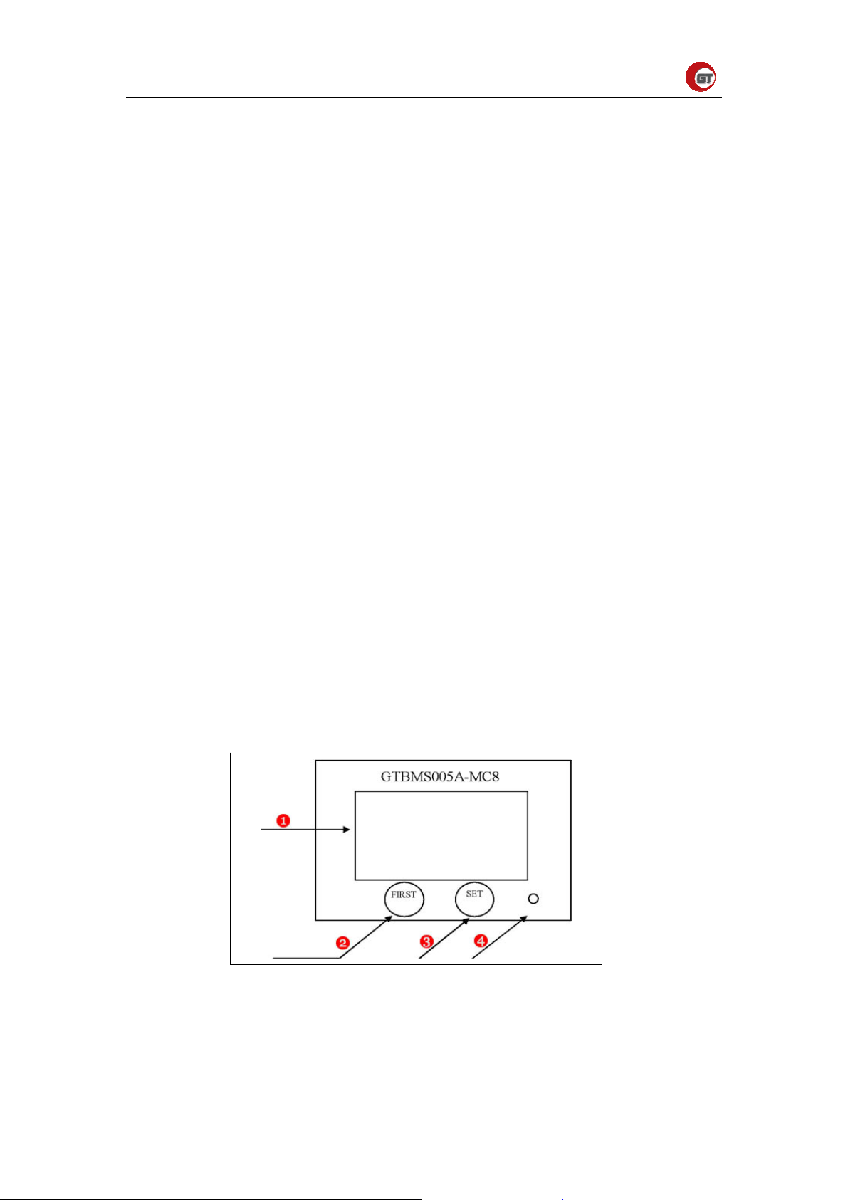
Main controller has two press keys, FIRST key and SET key; a ALARM indicator light
Man controller orthoptic diagram as follows:
Figure 1-3-1 key intro
display region --------①
first page key -------②
function key -------③
4
Page 6
GuanTuo Power
alarm light -------④
1. First page key:display first page information, includes: total voltage、total current、
single battery max voltage and its number、single battery min voltage and its number.
2. Set key:display all information except first page information, includes capacity,
consumed watt-hour, max temperature and its number, min temperature and its number,
voltage of each battery.
3.Alarm light: flashes while alarms.
a)System parameter setting
Under the first page state, keep pressing “SET” key for five seconds to get into system
running parameter set menu. Enter the password before getting into this menu, customer's
password is marked at the main controller back. System parameter include: the number of
batteries that each sampling module manages, voltage upper limit、voltage lower limit ,
voltage cut lower limit, temperature cut upper limit, current cut upper, etc.
System parameter should be set once after being installed and will save parameter
automatically, and will monitor and alarm according to parameter that is set.
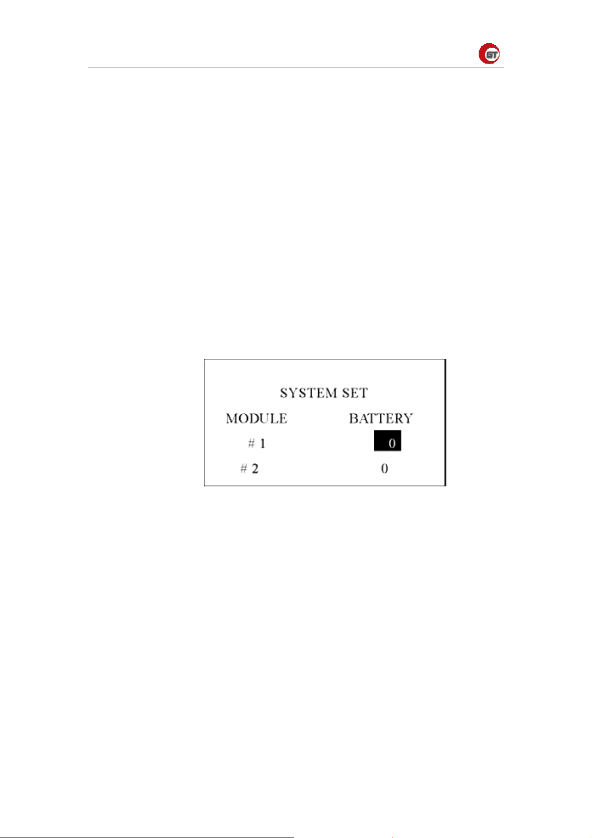
System running parameters diagram as follows: :
Figure 1-3-2 system parameters
MODULE :GTBMS005A-VCT sampling module address;#1 master module,#2 is slave
module。
BATTERY :the number of battery. If the number of batteries is less than ten ,#2 must set
as “0”.
Black frame is current editing content,“SET” key add 1,“FIRST” key is “ok”;Press
“FIRST” key,black frame will automatically move below. After setting #2 value, press
“FIRST” key to confirm,press “FIRST” key and “SET” key simultaneity to get into next
menu。Diagram as follows:
5
Page 7
GuanTuo Power
VOLTAGE
upper V alarm
4.20V
Figure 1-3-3
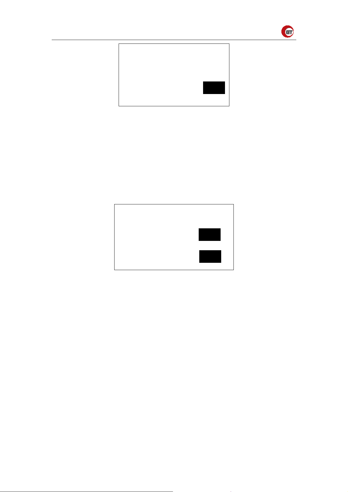
upper V alarm :When any battery voltage is larger than the value, system lightens the
LCD and provides a group of relay contacts to alarm. Normally , relay common contracts
are 5 switched on with N.C. contacts and cut off with N.O. contacts. When it’s alarming,
common contracts are switched on with N.O. contacts and cut off with N.C. contacts. If
the largest cell voltage drop and is 15mv lower than the value, the alarm will stop. Press
“SET” to add 1, press “FIRST” to subtract 1; if press “FIRST” and “SET” key at the same
time to get into the next menu. Diagram as follows:
lower V warn
lower V alarm
3.20V
3.00V
Figure 1-3-4system parameter
lower V warn:If any cell voltage is lower than the value, system will lighten the LCD and
buzzer to alarm. If the largest cell voltage drops and is 15mv lower than the value, the
alarm will stop.
lower V alarm :
If any cell voltage is lower than the value, system will lighten the LCD、
buzzer and provide a group of relay contacts to alarm. Normally , relay common contracts
are switched on with N.C. contacts and cut off with N.O. contacts. When it’s alarming,
common contracts are switched on with N.O. contacts and cut off with N.C. contacts. The
alarm won’t stop unless shut off the power. Press SET” keyto 1,press “FIRST ”key to
subtract 1;Simultaneity press “FIRST” key and “SET”key get into next menu. Diagram
as follows:
6
Page 8

GuanTuo Power
upper I alarm
upper T alarm
200A
65℃
Figure 1-3-5system parameter
upper I alarm :When total current is larger than the value,system will lighten the. LCD、buzzer
and provide a group of contacts to alarm. The alarm and “lower V alarm” share with the same
group of relay contacts.
upper T alarm :When the nods temperature is higher than the value, system will lighten.
the LCD、buzzer and provide a group of contacts to alarm. When the highest temperature
drops and is 5℃ lower than the value, the alarm will stop. The alarm and “lower V
alarm” share with the same group of relay contacts. Press “SET” keyto add 1,press
“FIRST” key to subtract 1;simultaneity press “FIRST” key and “SET” key back to home
page .
b) System initialization settings notice:
You must setup system running parameter once before using. System will memory it
automatically, without the need of set when you use it next time. But if you change the
main controller, you need to set the parameter again.
System will display first page information after being switched with the power, press
“set” key get into the next page, the information includes capacity, consumed watt-hour,
max temperature and its number, min temperature and its number, voltage of each battery,
press “FIRST” key back to first page.
7
Page 9
GuanTuo Power
2 Connection with chargers and motor
controller
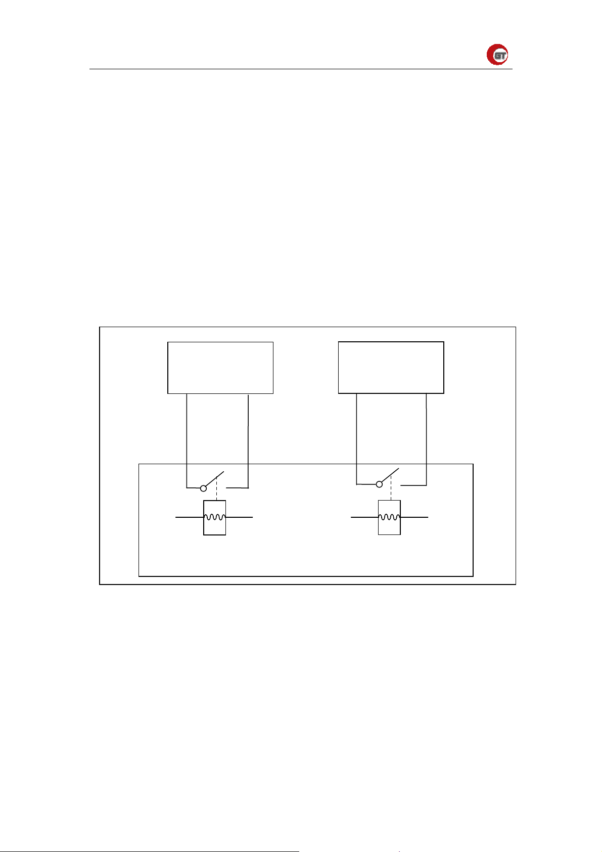
2.1 interface and connection
2PEL
connector
4P EL
connnetcor
6P EL
connector
Figure 2-1-1 wiring diagram
Figure 2-1-2 interface diagram
①2P EL interface connect with DC power。
8
Page 10
GuanTuo Power
②4P EL connect with data collection modules.
③6P EL separated two interfaces 3P ④⑤,connect with chargers and motor controller.
④connect with charger
⑤connect with motor controller
Notice:(we make wires according to battery distribution)we provide users with ELP ,ELR
connector。Motor controller ,chargers,must use the same way of relay .
2.2 System working principle
BMS-MC8 adopts relay switch to connect with circuit.When the
voltage,current,temperature,etc.reach the value set.Relay protects the battery through
connectiong and disconnection.
BMS(MC8)Management strategy
a1 b1 a2 b2
Pedal
REL1 B M S REL2
如图 1
Charger
BMS(MC8)can provide two relay node(no source)as alarm output.
When charging,one cell reach upper limit voltage alarm value(can set),BMS
control REL2 to shut.a2 and b2 connect,chargers can identify the signal.Then,chargers
begin to adjust output current to reduce the current. With reduced current, voltage
drops.When BMS detects all battary voltage less than upper limit alarm voltage,BMS
controll REL2 cut.Chargers can detect the signal.Chargers don’t minish current then
with the current goes on charging.Cycling the process until chargers stop output.
Through the way,BMS can protect battery from over charging.But,charges must can
9
Page 11

GuanTuo Power
identify the switch signal.
When discharging, we connect another replay with pedal circuit.BMS judges
battery group status ,if normal, REL1 shut. A1 and b1 connect, electric vehicle can
run.when running, single cell voltage lower than lower limit alarm voltage(can set,
Lithium iron phosphate battery suggest 2.8V).BMS screen alarm light can gleam and
beep.Drivers should reduce speed(minish battery current output).If the speed is not high, we
should charge battery.With the speed lower,voltage will rise again.When BMS detect all battery
voltage higher than lower limit alarm voltage(can set), alarm stops.When BMS alarms,drivers
don’t take steps,it will make battery below lower limit alarm voltage sostenuto
,BMS will cut
REL1.a1 and b1 will disconnect. Throttle will stop working.The electric vehicle can’t run.The
alarms can’t stop until we cut down the BMS power。
10
Page 12

GuanTuo Power
3 Notice and Contact
3.1 Notice
A. System initialization settings notice:
You must setup system running parameter once before using. System will memory it
automatically, without the need of set when you use it next time. But if you change the
main controller, you need to set the parameter again.
System will display first page information after being switched with the power, press
“set” key get into the next page, the information includes capacity, consumed watt-hour,
max temperature and its number, min temperature and its number, voltage of each battery,
press “FIRST” key back to first page.
B. Connect wires notice:
(we make wires according to battery distribution)we provide users with ELP ,ELR connector。
Motor controller ,chargers,must use the same way of relay.They can connect with BMS.So that
BMS protects batteries when charging and discharging.
Notice the connecting wires.According to stall definition of Figure strictly.
3.2 Contact us
Website:www.guantuo.com
tel:86-0451-57831822
address: Nangang District, Harbin, Heilongjiang Province, China
zip:150086
conntact:Fairy Yang
E-mail:[email protected]
11
 Loading...