

Page 1
HCS
COMPACT ELECTRONIC EMBROIDERY MACHINE
INSTRUCTION BOOK
CSK101-2
Page 2

Page 3

INDEX
0-0
IMPORTANT SAFETY INSTRUCTIONS.. 1-1
WARNING MARKS, LABELS, MEANINGS AND LOCATION ..
1-2
SETTING UP THE MACHINE
Remove the machine from box .............................2-1
Accessories...........................................................2-2
Assemble machine kit ...........................................2-3
Machine installation ..............................................2-4
Grounding instruction............................................2-6
Disposal of a battery .............................................2-6
MAIN PARTS ............................................ 3-1
HOW TO READ
THESE
INSTRUCTIONS .............
3-3
MESSAGE ................................................ 3-4
LET'S TURN ON THE MACHINE
How to turn on the machine ..................................3-5
If the display is not clear .......................................3-5
Calendar and clock setting....................................3-6
FUNCTION OF THE CONTROL BOX ...... 3-7
CONTROL MENU .............................................
3-9
INSERTING A NEEDLE............................ 4-1
SELECT NEEDLES AND THREADS....... 4-2
BACKING MATERIALS............................. 4-3
BOBBIN WINDING
Winding the bobbin ...............................................4-4
Removing the bobbin ............................................4-5
Inserting the bobbin ..............................................4-5
Adjusting bobbin thread tension............................4-5
Inserting the bobbin case......................................4-5
THREADING THE MACHINE
How to thread upper thread ..................................4-6
MACHINE SETTINGS............................... 5-1
PREPARATION OF PATTERN DATA
Connecting to a PC by Serial or USB connection.5-4
Reading embroidery pattern data from the PC .....5-4
Read embroidery pattern data from memory media
Select embroidery pattern from memory...............5-7
Erase embroidery pattern from memory ...............5-8
Erase all designs...................................................5-9
Export memorized pattern from memory ............ 5-9b
How to select monogram letters .........................5-10
SETTING AUTOMATIC COLOR CHANGE ...
5-5
5-15
SEWING WITH TUBULAR FRAMES
Installing and removing the frame base ................6-1
How to hoop..........................................................6-2
Putting the hoop in the machine ...........................6-3
Starting to sew ......................................................6-4
CAP FRAME (OPTION)
Changing the needle plate ....................................7-2
Installing and removing the cap drive frame .........7-3
Normal cap frame..................................................7-5
Wide cap frame.....................................................7-8
Starting to sew ......................................................7-B
ADJUSTING THE THREAD TENSIONS .. 8-1
ADJUSTING THE LASER POINTER (OPTION)...
8-2
SEWING
What to do if the thread breaks while sewing ...........
Stopping and resuming sewing .............................9-1
Loss of power while embroidering ........................9-2
Moving the hoop while embroidering then
returning to the correct location (Position) .......... 9-3
Moving to the beginning position of pattern
(Origin) ................................................................9-3
Going back to the start of design data (Top).........9-4
Placing the design in the center of the selected
embroidery frame (Center)..................................9-4
Rotating and mirroring designs (Convert) .............9-5
Starting from a midpoint of a design (F.Posi)............
9-1
9-6
OTHER SETTINGS
Create network......................................................9-8
LOG-IN • LOG-OUT • TURN-OFF ............ 9-B
SPECIFICATIONS • MAINTENANCE
Specifications ......................................................10-1
Oiling...................................................................10-1
Cleaning of the rotary hook
Cleaning the thread cutting knife ............................
10-2
ERRORS AND WHAT TO DO ................ 10-3
INITIALIZING OF MACHINE SETTINGS
Initializing of machine system ................. 11-1
Initializing of machine speed ................... 11-1
CHANGE OF THREAD BREAK DETECTION ....
11-3
HELPFUL HINTS .................................... 12-1
EMBROIDERY TERMS .......................... 12-2
BUILT-IN FONT LIST.............................. 12-3
-CS -2
0_0 I916
Page 4

IMPORTANT SAFETY INSTRUCTIONS
When using an electrical appliance, basic safety precautions should always be followed, including the following.
1-1
Read all instructions before using this appliance.
DANGER - To reduce the risk of electric shock:
1. An appliance should never be left unattended when plugged in. Always unplug this appliance
from the electric outlet immediately after using and before cleaning.
WARNING
1. Do not allow to be used as a toy. Close attention is necessary when this appliance is used
by or near children.
2. Use this appliance only for its intended use as described in this manual. Use only attachments recommended by the manufacturer as contained in this manual.
3. Never operate this appliance if it has a damaged cord or plug, if it is not working properly, if it
has been dropped or damaged, or dropped into water. Return the appliance to the nearest
authorized dealer or service center for examination, repair, electrical or mechanical adjustment.
4. Never operate the appliance with any air openings blocked. Keep ventilation openings of the
sewing machine and foot controller free from the accumulation of lint, dust, and loose cloth.
5. Never drop or insert any object into any opening.
6. Do not use outdoors.
7. Do not operate where aerosol (spray) products are being used or where oxygen is being
administered.
8. To disconnect, turn all controls to the off (“0”) position, then remove plug from outlet.
9. Do not unplug by pulling on cord. To unplug, grasp the plug, not the cord.
10.Keep fingers away from all moving parts. Special care is required around the sewing machine needle.
11.Always use the proper needle plate. The wrong plate can cause the needle to break.
12.Do not use bent needles.
13.Do not pull or push fabric while stitching. It may deflect the needle causing it to break.
14.Switch the sewing machine off (“0”) when making any adjustments in the needle area, such
as threading needle, changing needle, threading bobbin, or changing presser foot, etc.
15.Always unplug sewing machine from the electrical outlet when removing covers, lubricating,
or when making any other user servicing adjustments mentioned in the instruction manual.
- To reduce the risk of burns, fire, electric shock, or injury to persons:
SA VE THESE INSTRUCTIONS
-CS -3
1_1 F201
Page 5
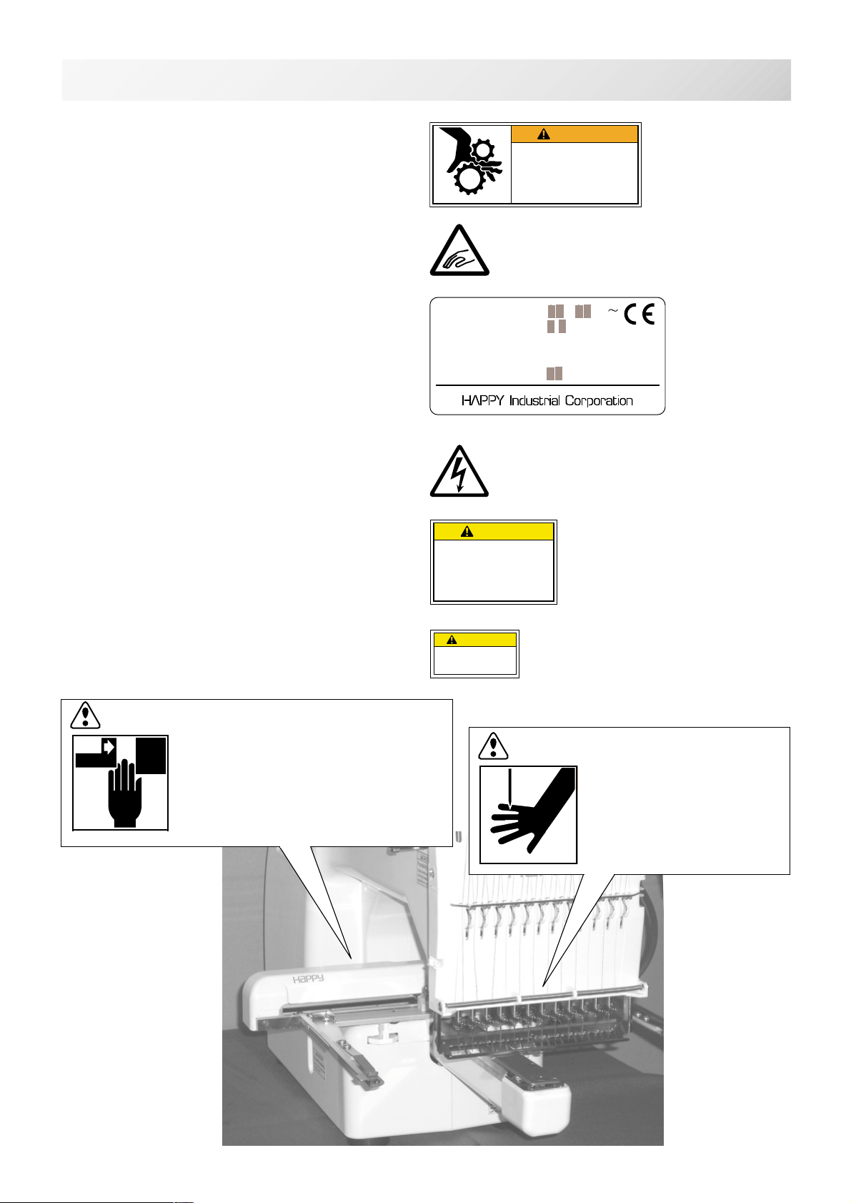
WARNING LABELS & THEIR LOCATIONS
1-2
Trapping hazard
Shut the cover when starting the machine.
Do not put hands in while the machine is running.
Trapping, Puncture, Cut hazard wherever this
label is found
Power Supply Voltage sticker
Risk of electrical shock and fire if the power
recommendations on this label are ignored!
Make sure that the power supply meets the exact
specifications as provided by the manufacturer.
Shock hazard on all electrical components
Injury risk on moving head(s)
Keep hands away from the moving heads while the
machine is running.
WARNING
Fear of serious injury.
Shut the cover when starting the
machine. Do not put hands in
while the machine is running.
VOLTAGE
AMPERE
PHASE SINGLE
FREQUENCY
POWER CONSUMPTION
CAUTION
Possibility of injury.
Keep hands away from the
moving heads while the
machine is running.
200-230V
1.1A
50/60Hz
220W
ES-HMF-5117-0
ES-HMF-5113-0
****
Laser beam (Class 1)
Do not stare into the beam.
CAUTION: Injury risk on frame and carriage
Keep hands away from the drive
frame while the machine is
running.
Catch a finger in the X-carriage.
CAUTION
Laser beam (Class1)
Do not stareinto the beam.
WARNING: Injury risk warning
for all needles
Keep fingers away from
the needles while
the machine is running.
-CS -6
1_2 K101
Page 6
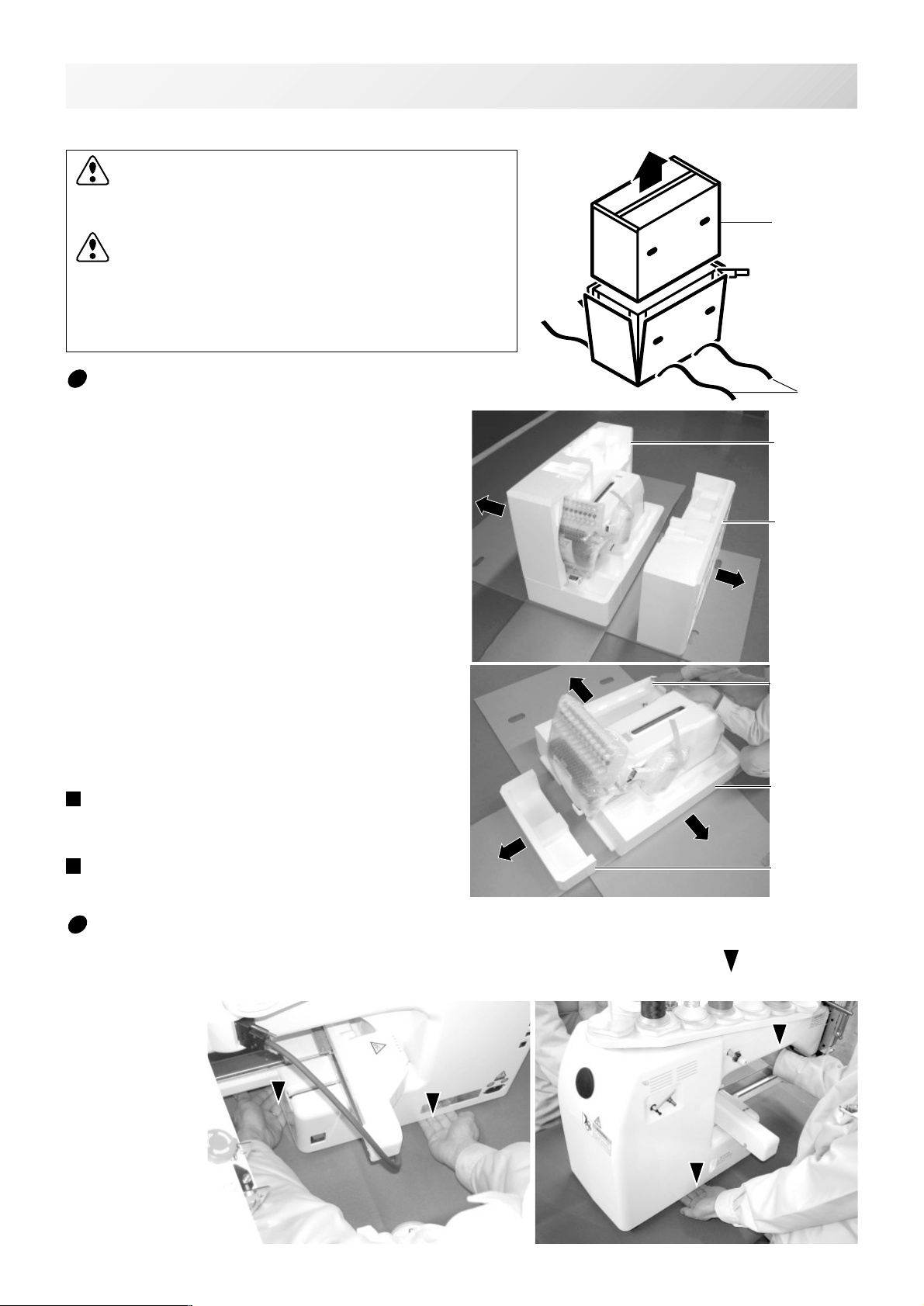
SETTING UP THE MACHINE
We recommend unpacking should be done where it has enough room.
CAUTION: To prevent accidents.
The machine is quite heavy for one person to carry.
Please use two persons when unpacking or carrying.
CAUTION: To avoid problems.
Make sure to hold bottom of the machine body when
removing from the box.
Do not hold any other place. (bed, moving head,
control box etc.).
2-1
Box (upper)
Remove the machine from box
1. Remove 2 straps from the carton.
2. Lift the box (upper) to remove.
3. Take out the accessories.
Refer to the next page.
4. Take out the styrene foam (right) and (left).
5. Take out the styrene foam (lower front),
(lower right), and (lower left).
Be careful not fall down the machine, tilt the
machine slightly when taking out the styrene
form (lower right) and (lower left).
6. Carry the machine to installation location.
Please keep those packing materials in
case of necessary for repair or other reasons.
Packing procedure is the reverse from
unpacking procedure.
Straps
Styrene
foam (left)
Styrene
foam (lright)
Styrene foam
(lower left)
Styrene foam
(lower right)
Styrene foam
(lower front)
How to carry machine
The unpacked machine should be carried by 2 person with the hand position at mark shown
in photos.
The person holding
the machine from
left side need to
hold the machine
arm by right hand.
Right side
Left side
-BD -5
2_1 K101
Page 7
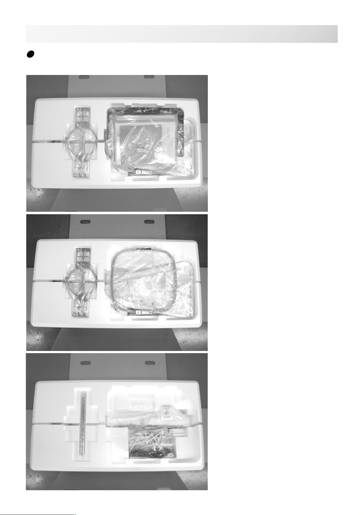
SETTING UP THE MACHINE
Placement of Accessories
Confirm all the accessories are contained when unpacking.
Frame base
CD-ROM
CD-ROM (HAPPY Link Software)
Instruction manual
Embroidery sample
2-1b
(Instruction manual, Parts list)
Embroidery frame (Round)
Embroidery frame (Square)
Thread stand
Thread guide bracket
Carriage
Thread stand felt (13 pcs)
USB cable
Power line cord ass'y
Tool set
Needle (10 pieces)
Fuse (6A)
Oiler
Sewing machine oil
Thread guide pillar (2 pcs)
Thread stand pin (13 pcs)
Wave washer (13 pcs)
-BD -6
2_1b K101
Page 8
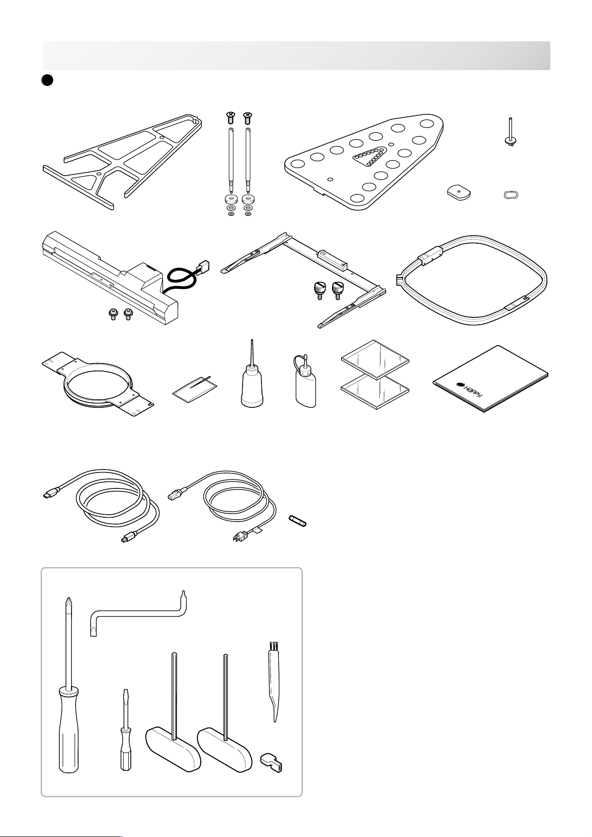
SETTING UP THE MACHINE
Accessories
Please confirm you have received the following.
2-2
5
Tools
21
1
78
10 11
17 18 19
20
22
23
12 13
24
2
463
9
14
15 16
1. Thread guide bracket
2. Thread guide pillar (2 pcs)
3. Thread stand
4. Thread stand felt (13 pcs)
5. Thread stand pin (13 pcs)
6. Wave washer (13 pcs)
7. Carriage
8. Frame base
9. Embroidery frame (square) PTA-32320-360
25
26
10. Embroidery frame (Round)
11. Needle (DB X K5) (10 pcs)
12. Oiler
13. Sewing machine oil
14. CD-ROM (Happy Link)
15. CD-ROM (Instruction manual, Parts list)
16. Instruction book (How to open the CD-ROM)
17. USB cable
18. Power line cord ass'y (A shape will be changed
depending on a destination)
19. Fuse (6A)
20. Off set screw driver HCB53050
21. #2 (+) Screw driver HCB53011
22. 2 mm (-) Screw driver HCB53020
23. 3 mm hexagonal driver HCB53130
24. 2.5 mm hexagonal driver HCB53120
25. Brush HCB53070
26. Manual lever
PTA-15-360
-CS -7
2_2 K101
Page 9

SETTING UP THE MACHINE
2-3
Assemble machine unit
1. Insert the thread stand pin with wave washer on the
thread stand by turning clockwise, Then insert thread
stand felt.
2. Put the thread stand on to the machine and insert the
thread guide pillar.
(set nut knob nut into the thread guide pillar and 2
washers)
Turn the thread guide pillar clockwise with a 3 mm
hexagonal driver until tight.
Turn the knob nut clockwise with a 3 mm hexagonal
driver until tight.
3. Install the thread guide bracket with supplied screws
(pan head screw M6 x 10 2 pcs).
4. Loosen the screw with a offset driver and remove the
red shipping collars that are equipped on the both side
of the guide bar. (
essary when packing.)
5. Put the carriage and carriage arm together with screw
(M4 X 8 2 pcs).
2 pins in the upper carriage arm will fit into holes on
the lower carriage.
6. Raise slowly the control box to the front then fix it with
2 supplied screws (M4 2 pcs).
7. Connect the cable of carriage to the machine with
fixed screw.
8. Install the arm for tubular embroidery. Please refer to
(page 6-1) "Installing and removing the frame base".
Or, Install the cap frame for the cap embroidery.
Please refer to (page 7-1) "Installing and removing the
cap drive frame".
Keep the shipping collars. It is nec-
1
2
3
2
When taking the machine apart in case of packing,
the process is opposite of assembling the machine.
Please do exactly the opposite way of assembling.
When packing the machine up for transportation,
be sure to select the sixth needle and fix it with
shipping collars on the both side of the guide bar.
4
5
6
7
-CS -8
2_3 I201
Page 10
SETTING UP THE MACHINE
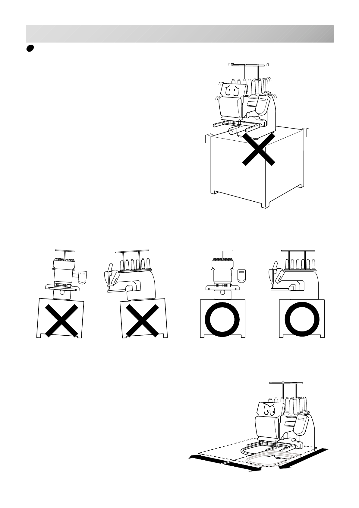
Machine installation
1. Please use a stout table to set the machine
on.
Please check for any shaking or excessive vibrating of the machine table when the machine is
running.
If you have a problem, Please use a stronger
table for the machine.
2-4
2. Please sit the machine level on the table.
3. Please be sure you have this much room
around your machine for it to move.
It is possible for the embroidery frame to hit you
and cause injury.
350 mm
350 mm
720 mm
-CS -7
2_4 D607
Page 11

SETTING UP THE MACHINE
4. Please be sure you have this much room around
your cap drive for it to move.
Please machine on the table positioning like right side
drawing.
5. Please do not sit the machine near any
kind of other electric equipment
(Examples: Microwave or electric tool).
Has possible to wrong movement of the
machine.
2-5
0 ~ 10 mm
6. Please keep away from dusty and high moisture environments.
Has case of rusting or damaging.
7. Please do not sit the machine in direct
sunshine or windy locations.
Has case of rusting or damaging.
-CS -82_5 D607
Page 12
SETTING UP THE MACHINE
2-6
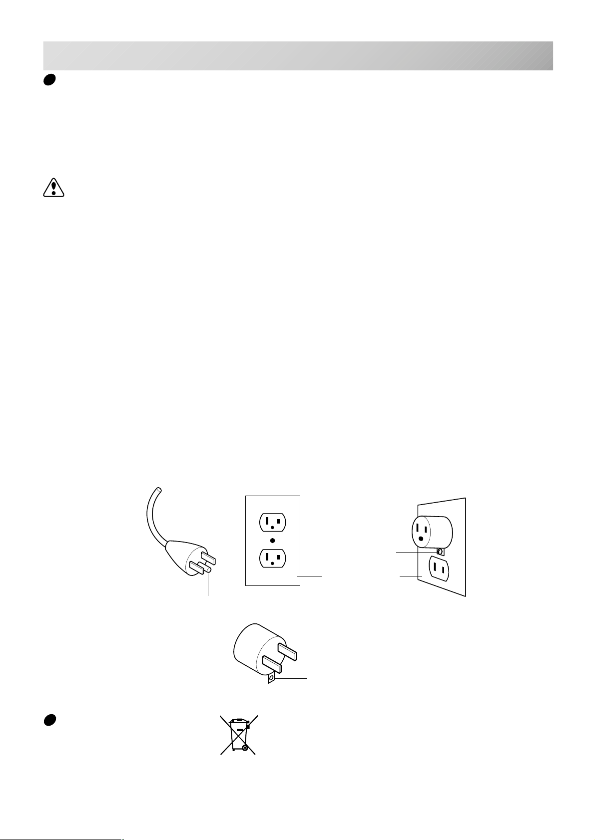
Grounding instruction (for type of 120V)
This product must be grounded. In the event of malfunction or breakdown, grounding provides a
path of least resistance for electric current to reduce the risk of electric shock. This product is
equipped with a cord having an equipment-grounding conductor and a grounding plug. The plug
must be plugged into an appropriate outlet that is properly installed and grounded in accordance
with all local codes and ordinances.
DANGER – Improper connection of the equipment-grounding conductor can result in a
risk of electric shock. The conductor with insulation having an outer surface that is green with or
without yellow stripes is the equipment-grounding conductor. If repair or replacement of the cord
or plug is necessary, do not connect the equipment-grounding conductor to a live terminal.
Check with a qualified electrician or serviceman if the grounding instructions are not completely
understood, or if in doubt as to whether the product is properly grounded.
Do not modify the plug provided with the product – if it will not fit the outlet, have a proper outlet
installed by a qualified electrician.
This product is for use on a nominal 120 V circuit, and has a grounding plug that looks like the
plug illustrated in sketch A in Figure. A temporary adaptor, which looks like the adaptor illustrated in sketches B and C, may be used to connect this plug to a 2-pole receptacle as shown in
sketch B if a properly grounded outlet is not available. The temporary adaptor should be used
only until a properly grounded outlet can be installed by a qualified electrician. The green colored rigid ear, lug, and the like, extending from the adaptor must be connected to a permanent
ground such as a properly grounded outlet box cover. Whenever the adaptor is used, it must be
held in place by the metal screw.
Grounding methods
Metal screw
Cover of grounded
outlet box
Grounding pin
A
Adapter
B
Grounding means
C
Disposal of a battery
A battery is had built-in to this embroidery machine.
When you dispose of a battery, according to each country or a method determined in each area,
please dispose appropriately.
-CS -11
2_6 I916
Page 13

MAIN PARTS
14
13
12
11
3-1
10
9
8
7
6
5
4
15
16
17
18
19
20
21
22
23
24
25
26
3
2
1
1. Hook cover
2. Bobbin case
3. Hook
4. Needle plate
5. Thread check spring
6. Take-up lever cover
7. Take-up lever
8. Lower rectifier
9. Thread tension
10. Detecting roller
11. Minor thread tension
12. Thread guide support
13. Thread guide
14. Upper rectifier
15. Thread stand pin
16. Thread stand felt
17. Thread stand
18. Needle bar selection knob
19. Control box
20. Serial port
27
21. USB port (based on the USB)
22. LAN Port
23. Frame base
24. Carriage
25. Fuse (6A)
26. Terminal box
27. Power switch
-CS -12
3_1 I331
Page 14
MAIN PARTS
3-2
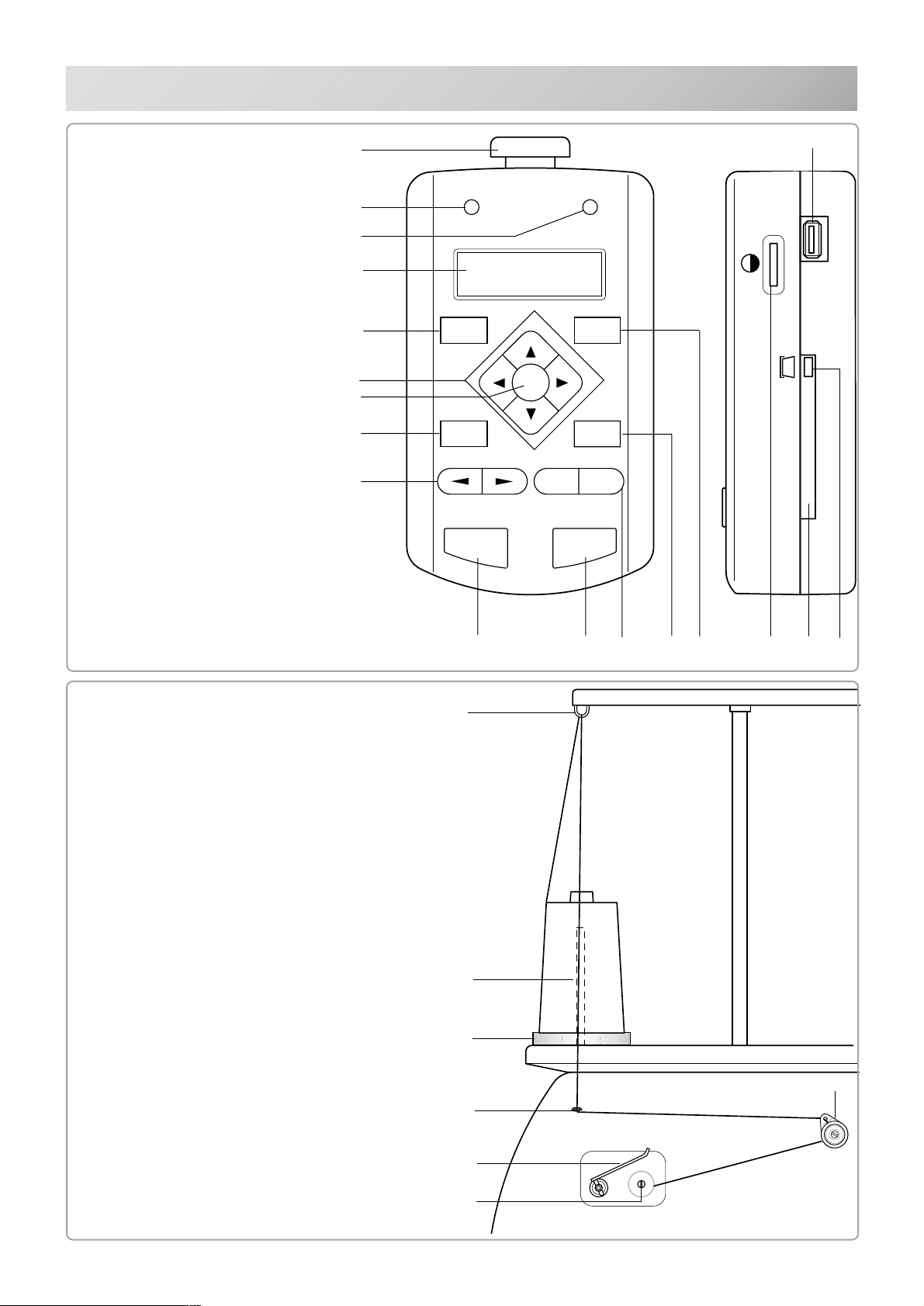
CONTROL BOX
31. Emergency stop button
32. Drive lamp
33. Thread break lamp
34. Display (L.C.D.)
35. Menu button
36. Forward button
37. Arrow button (Up, Down,
Left, Right)
38. Enter button
39. Pressure foot button
40. Thread cut button
41. Needle change button
42. Speed control button
43. Start button
44. Stop button
45. Contrast control dial
46. Memory card eject button
47. Memory card slot
48. USB memory port
31
32
33
34
35
37
38
39
41
ERROR
MENU
ENT.
P.FOOT
-
START STOP
48
T.BREAKDRIVE
FORW ARD
T.CUT
+
BOBBIN WINDING
49. Upper Thread guide
50. Thread stand pin
51. Thread stand felt
52. Thread guide
53. Thread tension
54. Spindle
55. Lever
43 44
49
50
51
42
40
36
45
47
46
53
52
55
54
-CS -133_2 H701
Page 15
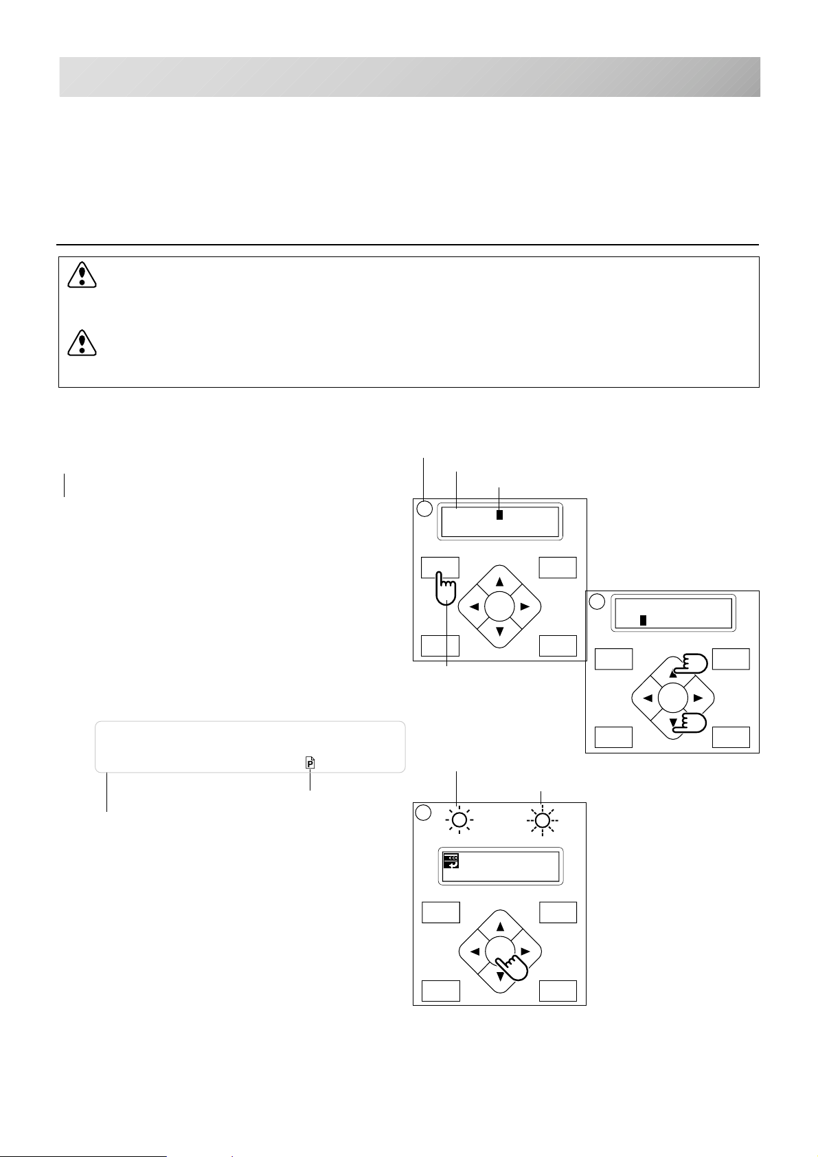
P.FOOT T.CUT
MENU
FORWARD
ENT.
P.FOOT T.CUT
MENU
FORWARD
ENT.
HOW TO READ THESE INSTRUCTIONS
FORWARD
P.FOOT T.CUT
MENU
ENT.
G
3-3
This manual consists of the following instruction.
We will display the items on the left with graphics on the right to clearly show the steps necessary to perform any function.
Graphics at the far right will show the display after performing the requested steps.
CAUTION: To prevent accidents.
This will appear for items related to your safety.
CAUTION: To avoid problems.
This will appear for items related to potential problems.
Order of operation
Order of operation
Indicate menu item
Cursor : Presently selected item
1. When the machine is stopped, Press
“MENU” button until display shows [MENU].
2. Select the design name you wish to sew, by
use of the up and down arrow buttons.
3. When you press the "ENTER" button, the
machine will return to drive mode.
If you wish to cancel of your selection, Press the
down arrow button then press ENT.
(Drive lamp will change to green) 3-4
This indicates an
This indicates supplementary
explanation on operation or action
of the machine against operation.
additional explanation on an
operation.
Sample page No.
for more detail.
1
[MENU] Pattern
Needle
Showing the button
to be pressed
"G" indicating the lamp is
glowing Green to show the
machine is ready to sew.
"R" indicating the lamp is
glowing Red to show an error
has occurred.
3
ID:10 Nd: 4
BIRD
This lamp will blink to
show a thread break.
2
[SELECT](ID:10)
14 FANTASIA
-CS -12
3_3 D607
Page 16
FORWARD
MENU
P.FOOT
T.CUT
ENT.
START STOP
+
-
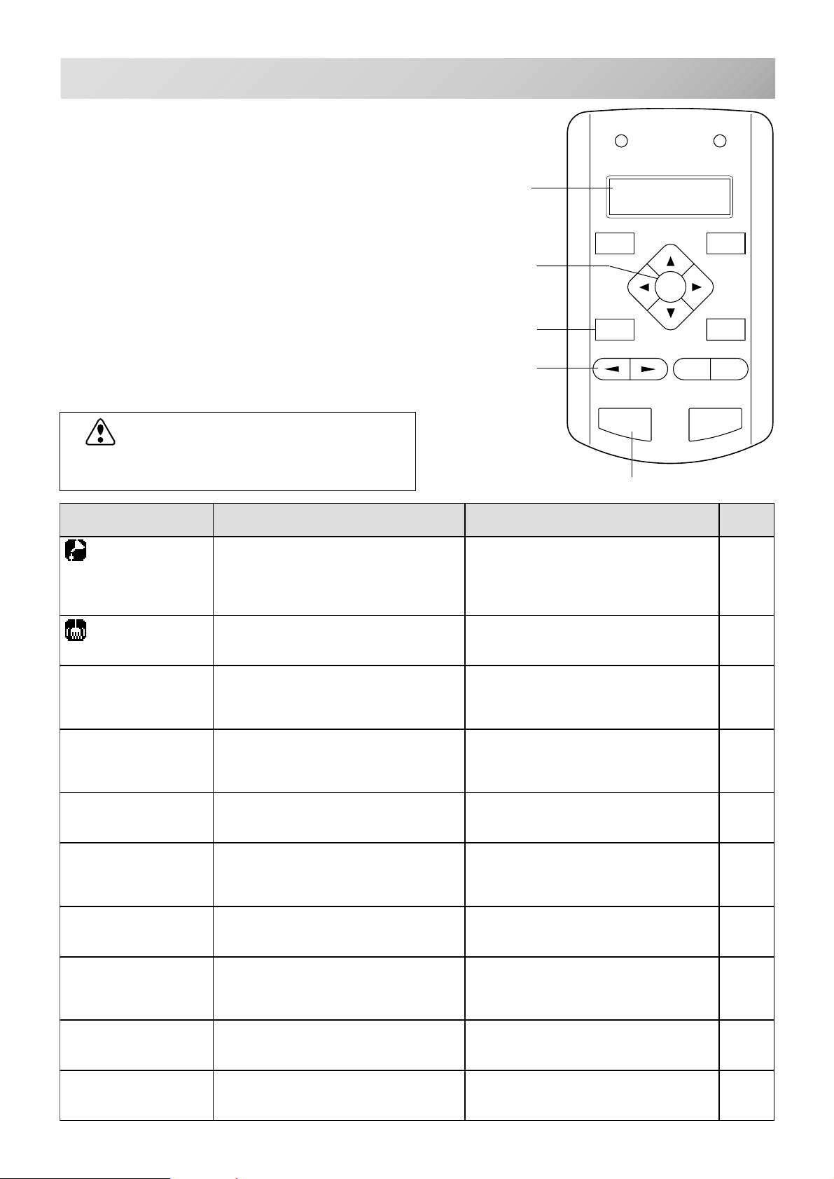
MESSAGE
If the machine shows an message when turn
on the power, or when you stop the machine by
pressing the “STOP” button.
Please proceed as shown in the following table.
CAUTION: To prevent accidents.
The embroidery frame may move. Please
remove your hand for your safety.
Message
Enter button
Pressure foot button
Needle selection button
3-4
>>Stop Switch
Start button
dnE>>
BA
EGASSEM NOITANALPXE NOITAREPO EGAP
yalpsidehtnoretteldetangiseD
!!noituaC
?roloC>>
dneecarT>>
.detacirbuleboteudsi
ehtdnakoohyratorehtnaelC
.efinkgnittucdaerht
ezingocerotevomlliwemarF
sevomemarF
hctiwSpotS>>
.ngised
.ngised
potSegnahC>>
.noitcnuf"tniop
kaerBdaerhT>>
.ecartngised
tooferusserP>>
.noitisopemarflautcaeht
deppotssienihcamehT
sawnottubpotsehtesuaceb
ehtgnirediorbmeelihwdesserp
deppotssienihcamehT
ehtdehsinifsahtiesuaceb
uoyesuaceb,deppotsenihcaM
egnahcroloctapotS"desu
uoyesuaceb,deppotsenihcaM
.oNroloctxentcelestondid
esuaceb,deppotsenihcaM
.nekorbdaerhtnibbobroreppu
deppotssienihcamehT
ehthtiwdehsinifsahtiesuaceb
.nwodsitooferusserPputfilotnottub"TOOF.P"sserP
.BroAyb
.nottub”RETNE“
.nottub"RETNE"
"ehtsserpuoynehWRETNE"
.noitisop
.yrediorbmeemuser
.emarf
.yrediorbme
.notub"TRATS"
detacidninoitacolehtetacirbuL
niegapdetacidniehtotrefeR
ehtsserpnehtlaunamsiht
ehtninoitcurtsnihtiwnaelC
ehtsserpnehtegapecnerefer
suoiverpehtotnruterdnaevom
otnottub"TRATS"ehtsserP
,ngisedtxenwesothsiwuoyfI
yrediorbmeecalperesaelP
"TRATS"ehtsserpuoynehW
tceleslliwenihcameht,nottub
emuserdnaroloctxeneht
.yllacitamotuagnirediorbme
eldeentxentcelesesaelP
"noitceleseldeeN"ybrebmun
."TRATS"ehtsserpnehtnottub
rodaerhtreppudaerhtesaelP
sserpnehtdaerhtnibbobkcehc
emuserotnottub"TRATS"
sserpnehT.tooferusserpeht
1-01
2-01
5-3
lliwemarfyrediorbmeeht,nottub
.KOfinottub"TRATS"ehtsserP4-6
6-7
-CS -13
3_4 E201
Page 17
LET'S TURN ON THE MACHINE
FORWARD
P.FOOT T.CUT
MENU
ENT.
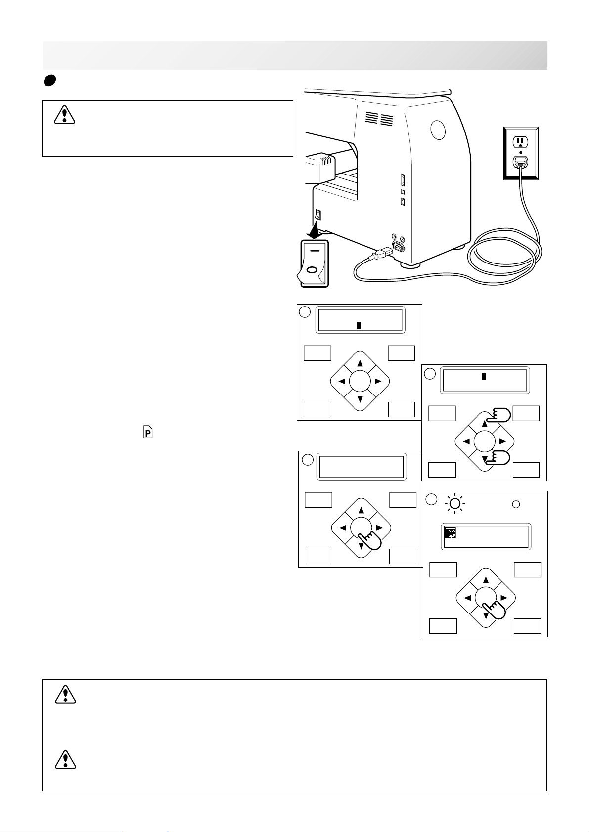
How to turn on the machine
CAUTION: To prevent accidents.
The embroidery frame and carriage will move.
Please remove your hand for your safety.
1. Please connect power line cord to inlet on
right side of the machine.
3-5
2. Connect the power line plug to the electric
outlet.
3. Turn on the power switch.
Push the power switch firmly so it will remain on.
4. Press the “Up” or “Down” Arrow button until
the cursor points to "Tubular".
Please select "Other", only when you use special
shape frames. 3-5b
5. Press the "ENT.” button.
6. Press the "ENT.” button.
The embroidery frame will return to the previous
position automatically.
ON
OFF
3
[Frame] Tubular
Other
MENU
FORWARD
ENT.
P.FOOT T.CUT
5
Caution !!
Frame Moves
4
[Frame] Tubular
Other
MENU
FORWARD
ENT.
P.FOOT T.CUT
6
G
ID:10 Nd: 4
BIRD
To disconnect, switch the power switch to the
off position, then remove plug from outlet.
DANGER: To reduce the risk of electric shock.
Never leave the machine unattended when plugged in.
Always unplug this machine from the electric outlet immediately after using and before maintenance.
WARNING: To reduce the risk of burns, fire, electric shock, or injury to persons.
Do not unplug by pulling on cord. To unplug, grasp the plug, not the cord.
MENU
FORWARD
ENT.
P.FOOT T.CUT
-CS -16
3_5 K101
Page 18
LET'S TURN ON THE MACHINE
FORWARD
P.FOOT T.CUT
MENU
ENT.
3
FORWARD
P.FOOT T.CUT
MENU
ENT.
1
FORWARD
P.FOOT T.CUT
MENU
ENT.
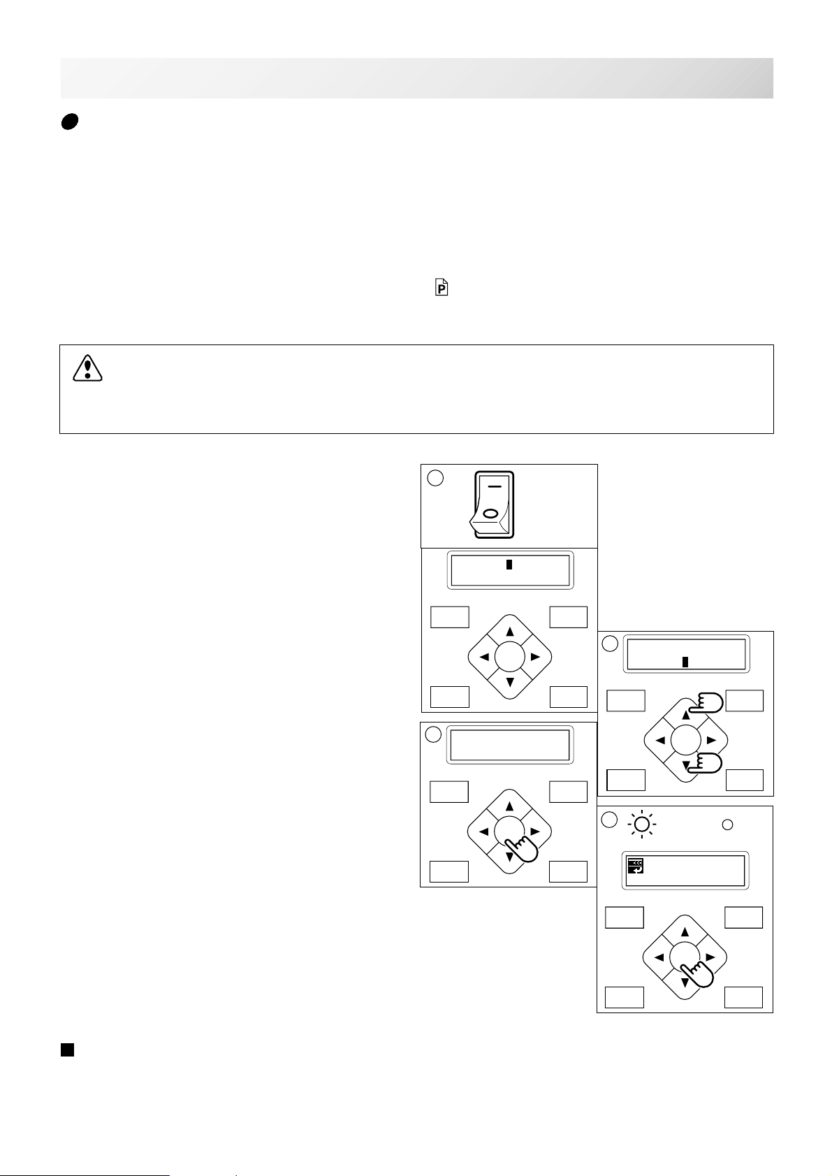
3-5b
Non registered
In case Non Registered Frame is selected, carriage does not have movement for creating the
coordinates of frame position at the time of turning machine on.
Please select Non Registered Frame, when you need use special frame which can hit pressure
foot or other machine parts by movement of carriage for creating the coordinates of frame position.
The following functions is canceled by selecting Non Registered Frame;
* Restore the position at the time of power failure
9-2
* Autostop function when movement exceeds the carriage limit.
Except using special shape frame, please do not select Non Registered Frame.
In case you have operation mistake, needle and/or pressure foot may hit frame and machine
and/or frame can be damaged.
1. Turn on the power switch.
ON
OFF
[Frame] Tubular
Other
2. Press the “Up” or “Down” Arrow button until
2
the cursor points to "Other" (Non registered).
[Frame] Tubular
Other
MENU
3. Press the "ENT.” button.
4. Press the "ENT.” button.
Caution !!
Frame no limit
P.FOOT T.CUT
4
BIRD
ENT.
G
ID:10 Nd: 4
When you need to change from Non Registered frame to other type of frame, please powor
machine off and start again.
Without re-starting machine, machine will move incorrectly.
FORWARD
-CS -17
3_5b K101
Page 19
LET'S TURN ON THE MACHINE
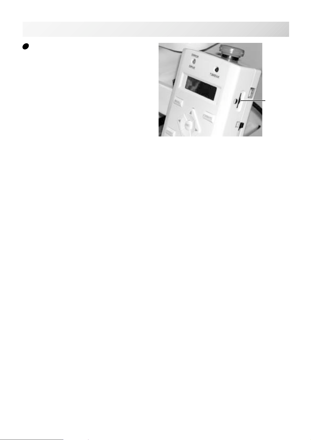
If the display is not clear
Please adjust the contrast of the LCD display by
turning the small dial on the right side of the
control box.
3-5c
Contrast
control dial
-CS -18
3_5c H701
Page 20
P.FOOT T.CUT
MENU
FORWARD
ENT.
P.FOOT T.CUT
MENU
FORWARD
ENT.
P.FOOT T.CUT
MENU
FORWARD
ENT.
P.FOOT T.CUT
MENU
FORWARD
ENT.
LET'S TURN ON THE MACHINE
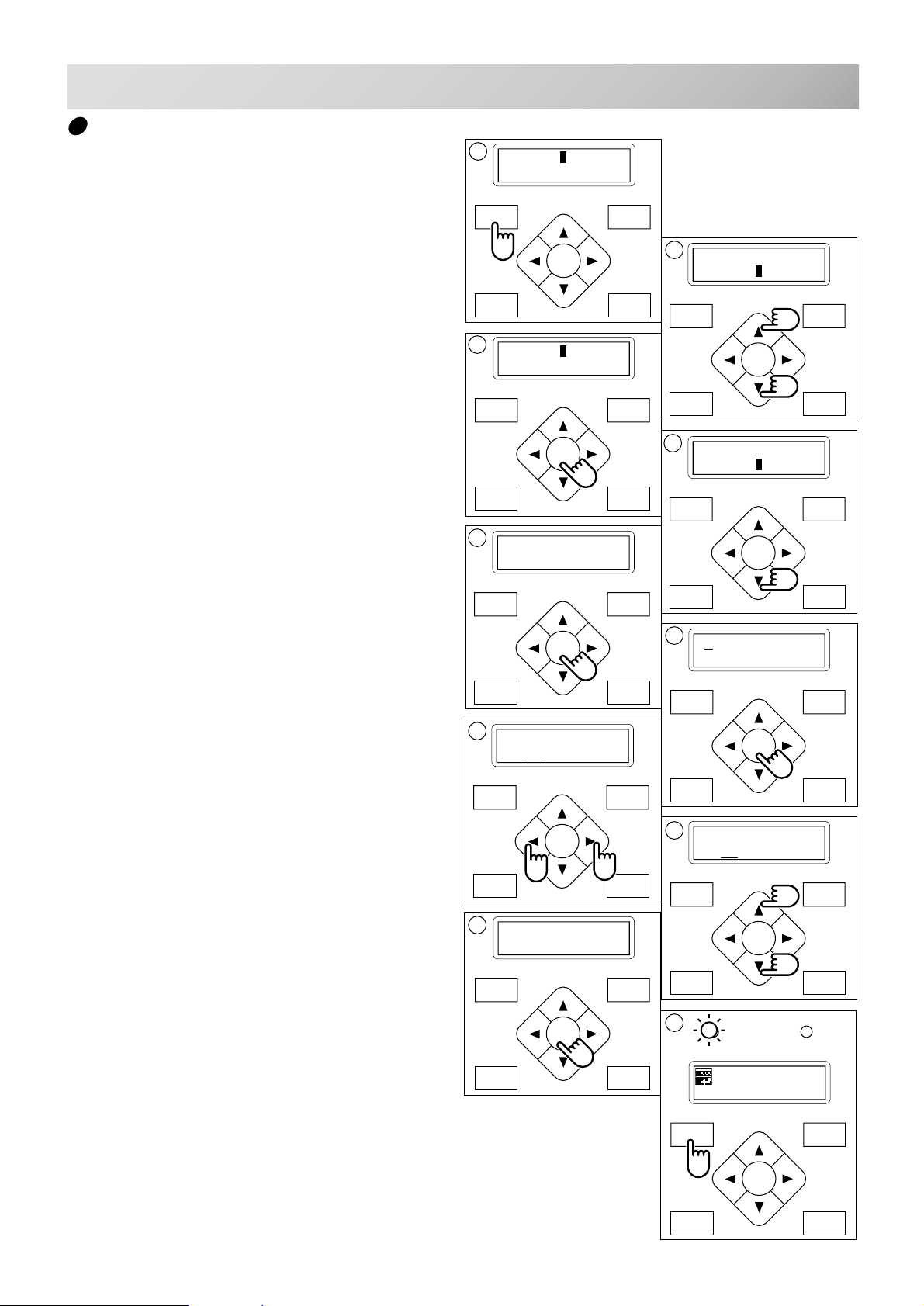
Calendar and clock setting
If you set up the calendar and clock, the machine will advise when oiling and other maintenance is scheduled to occur.
1
3-6
[MENU] Pattern
Needle
1. Press the "MENU" button until the display
shows [MENU] while the machine is
stopped.
2. Select "Other" by pressing the up and down
"Arrow" buttons.
3. Press the "ENT.” button.
4. Select "Clock" by pressing the down "Arrow" button.
5. Press the "ENT.” button.
The display will show the month, date, year, day
and time.
6. Press the "ENT.” button.
A cursor ( _ ) will appear at the bottom of the
month. You can then set the number.
3
[OTHER] Setup
Clock
5
1.23.2003.THU
10:09:56
MENU
ENT.
FORWARD
2
[MENU] Letter
Other
MENU
FORWARD
ENT.
P.FOOT T.CUT
4
[OTHER] Setup
Clock
MENU
FORWARD
ENT.
P.FOOT T.CUT
6
1.23.2003.THU
10:09:56
7. Move the cursor to the next item you wish
to change by using the “right” and “left”
Arrow buttons.
8. Change the numbers by using the “up” and
“down” Arrow buttons.
9. Press the "ENT.” button.
If you wish to change other item of calendar and
clock, Please continue 7. and 8.
10.Finally, Press "MENU" button until the
green lamp is showing on the control box.
If a green lamp is showing, you are in “Drive”
mode.
P.FOOT T.CUT
7
1.23.2003.THU
10:09:56
9
1.23.2003.THU
10:10:56
MENU
FORWARD
ENT.
P.FOOT T.CUT
8
1.23.2003.THU
10:10:56
MENU
FORWARD
ENT.
P.FOOT T.CUT
10
G
ID:10 Nd: 4
BIRD
MENU
FORWARD
ENT.
P.FOOT T.CUT
-CS -15
3_6 D424
Page 21
FUNCTION OF THE CONTROL BOX
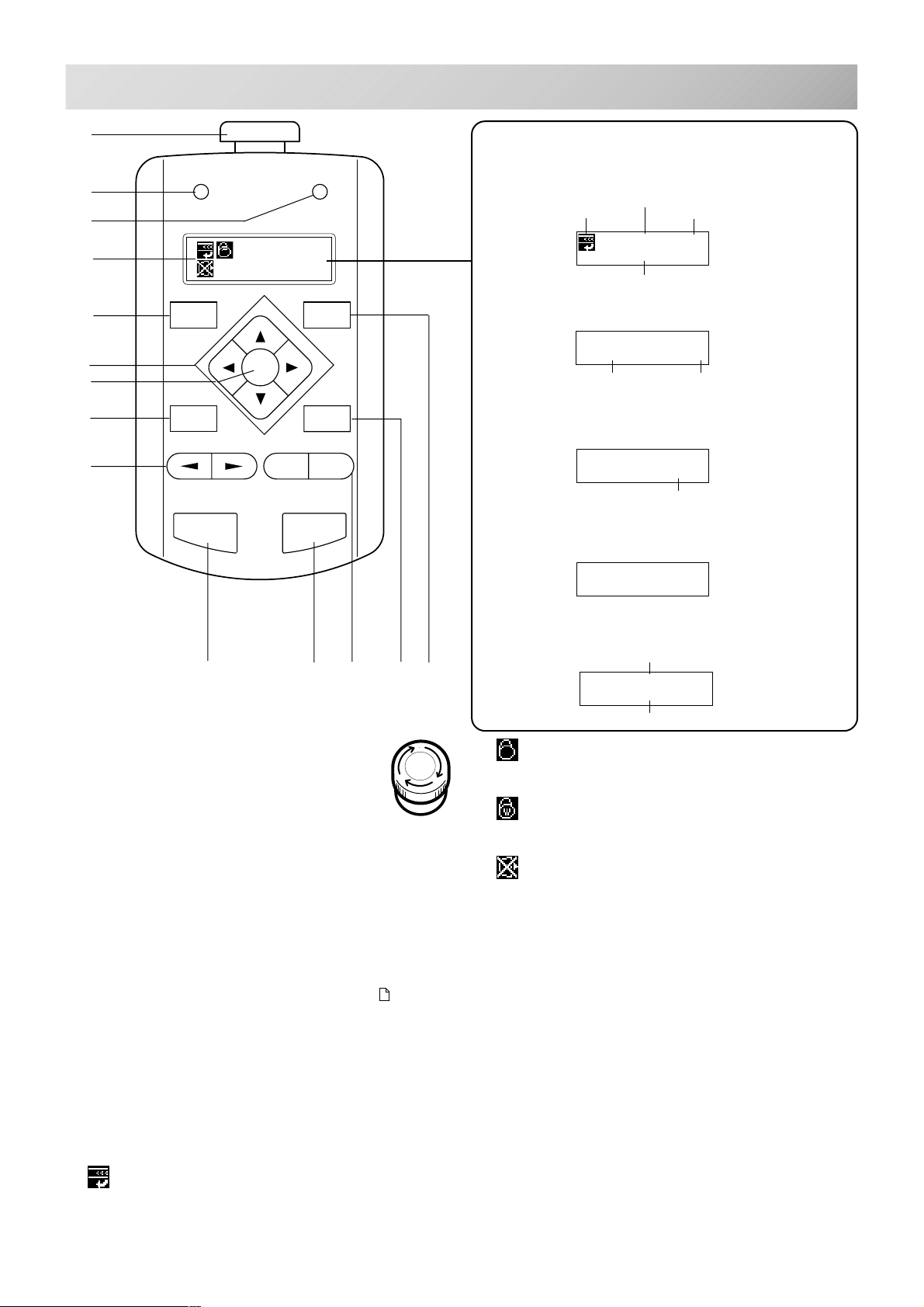
3-7
B
C
D
E
F
G
H
A
I
ERROR
MENU
ENT.
P.FOOT
-
START STOP
T.BREAKDRIVE
FORW ARD
T.CUT
+
Display example
When beginning an embroidery
Selected memory registration number
Top
ID:10 Nd:12
FLOWER
Selected pattern name
While embroidering
ID:10 Nd:12
123456 1000
Number of stitches
sewn up to now Speed
Machine stopped during embroidering
ID:10 Nd:12
123456
Number of stitches sewn up to now
Display if the machine has no design
in memory
Nd:12
HAPPY
Present needle number
Speed
JK
L
A. Emergency stop button
When you press this button, the power is
switched off and the machine stops.
The Emergency button will be locked,
whenever it is pushed.
To unlock, turn the emergency button to the right
(Arrow direction) then release and the button will
unlock.
Please use this button only for emergency.
B. Drive lamp
Green .................... You can start embroidery.
Red ........................You have a machine error.
an error number will be shown
on the LCD screen. 10-3
C. Thread break lamp
Blinking red lamp... Indicates the upper thread has
broken or the Bobbin thread
has run out.
D. Display
Shows the embroidery design name, the number of
the current needle and other machine generated
messages.
Top
This icon when displayed indicates that the machine is ready to start sewing from the top of the
design.
M
Display when manually moving the
hoop
Moving distance of X
N
X:-234.5
Y: 123.8
Moving distance of Y
Normal cap frame
Shows cap drive frame is set and normal cap
frame is available.
Wide cap frame
Shows cap drive frame is set and wide cap frame
is available.
Do Not Remove the memory media
Please do not remove memory media when this
icon is displayed.
If you remove the memory media when this Icon
is displayed, it is possible to corrupt the design
data in the machine memory and on the memory
media.
E. Menu button
Displays the function menu for the machine settings and the design set-up.
F. Arrow button (Up, Down, Left, Right)
The frame moves toward direction of the arrow
mark on the pressed button.
G. Enter button
If you depress this button while also pressing an
arrow button, the frame will move more quickly.
H. Pressure foot button
You can raise or lower the presser foot .
Showing distance
on X and Y from
origin point
-CS -18
3_7 H701
Page 22
FUNCTION OF CONTROL BOX
3-8
I. Needle change button
Move the sewing head in the direction of the
arrows.
J. Start button
Machine starts working.
If you press this button while the machine is
running, the machine will switch to “inching”.
(Super slow speed)
The Machine will return to the previous speed
when you remove your finger from this button.
If you use the inching function for an extended
length of time it is possible to influence the
stitch quality.
If you press start button when the take up lever
cover is open, an error message will be shown.
You cannot start embroidery when take up lever
cover is open.
10-4
K. Stop button
The machine stops when pressed.
When the Stop button is pressed while the Drive
Lamp is blinking (green color), the followings will
come due to how the Stop button is pressed.
Press one time ........... The frame move back one
stitch.
Keep pressing .............
Keep pushing longer ...
Keep pressing still longer...
The frame will move
backwards continuously.
Function of button is
locked. The frame goes
back by 1 stitch at a time
continuously. Push the
stop button again to stop it.
Function of button is
locked. The frame goes
back by 10 stitches at a
time continuously. Push
the stop button again to
stop it.
L. Speed control button
Press the + button to increase the machine sewing
speed and the - button to lower the machine
speed. The sewing speed is shown on the display.
M. Thread trim button
The Machine will cut the upper and lower thread
when this button is pressed.
CAUTION: To prevent accidents.
If you press the thread trim button, the needle
will penetrate the fabric. Please keep your
hands clear for your safety.
R
OPQ
Keep pressing longer ..
Keep pressing still longer...
Function of button is
locked. The frame will
move forward by 1 stitch
continuously. Push the
“STOP” button to stop it.
When you stop it, push
stop button.
Function of button is
locked. The frame will
move forward by 10
stitches continuously.
Push the “STOP” button
to stop it.
When you stop it, push
stop button.
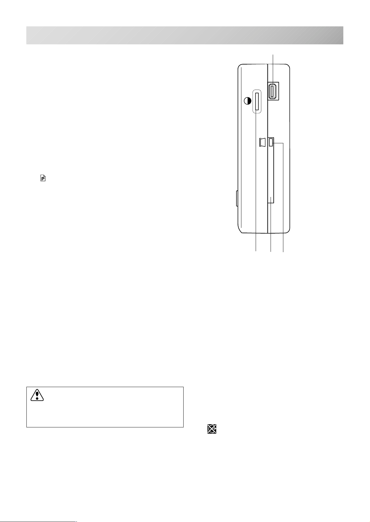
O. Contrast control dial
Adjust the contrast of the display by turning the
contrast control dial.
P. Memory card eject button
Press this button to take out the memory card.
Please do not remove the memory card when the
icon is displayed on the LCD display.
N. Forward button
Press one time ........... The frame moves forward
one stitch.
Keep pressing............ The frame will move
forward continuously.
Q. Memory card insertion slot
PCMCIA card socket for installing the memory
cards.
R. USB memory port
USB memory socket.
-CS -19
3_8 H701
Page 23
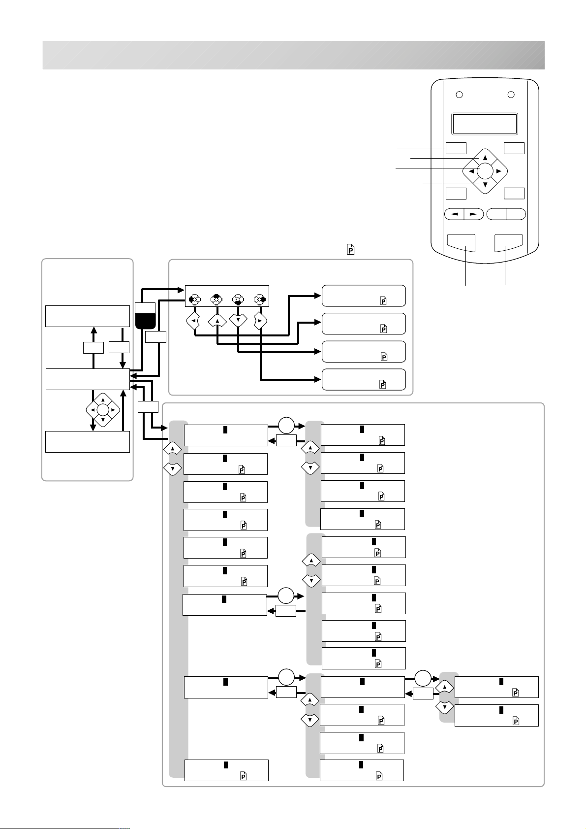
CONTROL MENU
FORWARD
MENU
P.FOOT
T.CUT
ENT.
START STOP
+
-
MENU
This page shows the relationships for all machine functions. (Drive mode and Function menu)
You can start embroidery and manually move the frame
only in Drive mode.
If you keep pressing a "MENU" button longer than 1
second, the direct frame movement menu will come up.
Use the "MENU" button to switch between Drive mode
and Menu mode. If you press the "MENU" button from
Drive mode, you will be switched to Menu mode. Then
you can select any function by the up and down arrow
keys. Pressing the “ENT” key enters your choice.
If you press the "MENU" button from any point in the
Menu mode, you will change to Drive mode.
3-9
Menu button
Up arrow button
Enter button
Down arrow button
Explanation page
DRIVE
START
ID:10 Nd:12
123456 1000
STOP
START
STOP
ID:10 Nd:12
123451
ENT.
Frame move
X:-234.5
Y: 123.8
MENU
Keep
pressing
MENU
MENU
DIRECT FRAME MOVEMENT MENU
Org Top Cnt Pos
Original point return
Top 9-4
Frame center 9-4
Position return
9-3
9-3
MENU
[MENU] Pattern
Pattern data
[MENU] Needle
Auto.needle change
5-15
[MENU] Read
Memory media
5-6
[MENU] Convert
Convert 9-5
[MENU] F•Posi
Frame position
9-6
[MENU] Create
Create 5-1
[MENU] Letter
Emb. letter
[MENU] Other
Other
ENT.
MENU
ENT.
MENU
ENT.
MENU
[PAT.] Select
Select 5-7
[PAT.] Erase
Erase 5-8
[PAT.] All clr
All clear 5-9
[PAT.] Write
Export 5-9b
[LETTER] Char
Character 5-10
[LETTER] Area
Area 5-11
[LETTER] Size
Size 5-12
[LETTER] Style
Style 5-12
[LETTER] Mode
Mode 5-13
[OTHER] Setup
Setup
ENT.
Start button
Stop button
[SETUP] System
System initialize
11-1
[MENU] Log
Log-in•Log-out
9-B
[OTHER] Clock
Clock 3-6
[OTHER] Detect
T.break detection
11-3
[OTHER] Net
Network 9-8
[SETUP] Speed
Speed setting 11-1
-CS -203_9 H701
Page 24
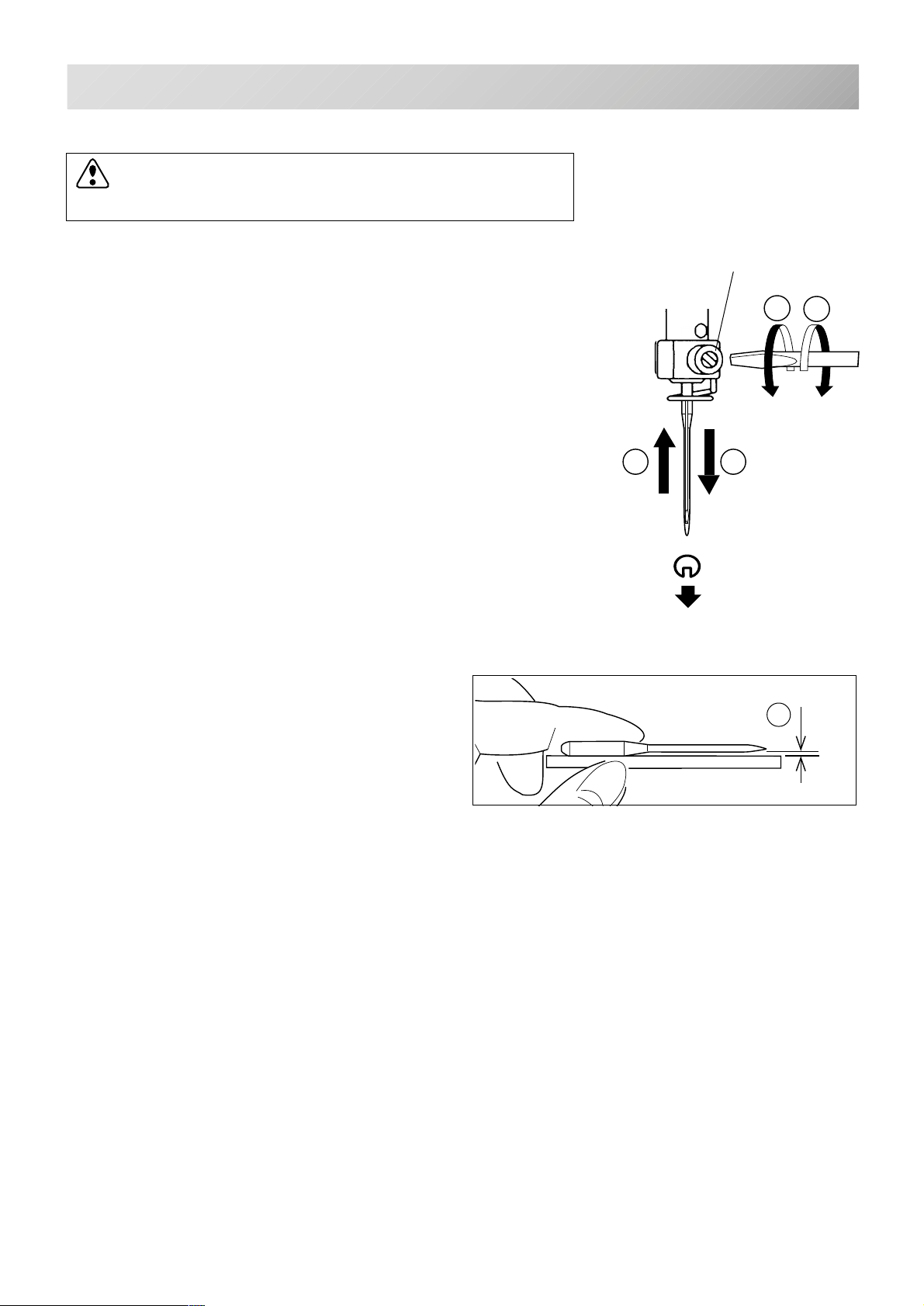
INSERTING A NEEDLE
Select a needle of the right type. See the following “SELECT THREADS”.
CAUTION: To prevent accidents.
Turn off the power before removing the needle.
4-1
1. Loosen the needle clamp screw slightly with the screwdriver.
2. Remove the needle.
3. Insert a new needle into the needle clamp with push it up
as far as it will go keeping the slotted side of the needle in
front.
4. Tighten the needle clamp screw with the screwdriver.
A. Do not use a bent or blunt needle.
Place the needle on a flat surface and check
for straightness.
Needle clamp screw
1
4
3
2
Front
A
-CS -19
4_1 D424
T
S
Page 25
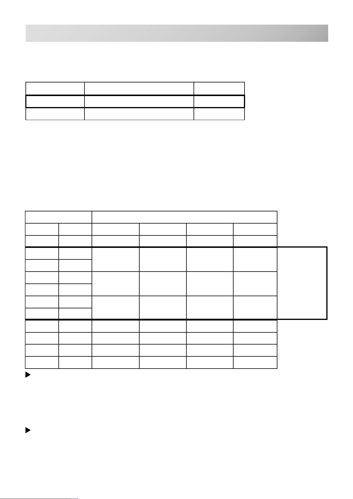
SELECT NEEDLES AND THREADS
About needle
Please select needles by type of material .
Normally, We supply a DB X K5 needle as in the machine accessory kit.
4-2
EPYTNOITACILPPA
5KXBDyrediorbmelamronroF81~9
32K-BDtinkroF21~9
Relation of needle and upper thread
Please select type of needle and upper thread by flowing list.
eziSdaerhtreppudnaeldeenfonoitaleR
nagrOnamreG#nottoCkliSretseyloPnoyaR
8#06#031~001061~041002~05107~05
956
08~07021~001051~031001~07
0107
eziSeldeeN
1157
06~05001~08031~001031~001
2108
3158
04~6307~06001~08051~031
4109
5159
6100163~0306~0508~06061~051
71501
8101103~4205~0406~05032~081
Normal embroidery field
Normal use embroidery needle and upper thread.
Upper thread : Rayon 120 d/2 (120 denier)
Polyester 120 d/2 (120 denier)
Needle : #11 ( DB X K5 )
If the relationship of needle size and thread type is incorrect, it is possible to have any of the
following problems.
• Thread break
• Skip stitch (Upper thread does not catch bobbin thread)
• Other stitch quality problem
-CS -20
4_2 D607
Page 26
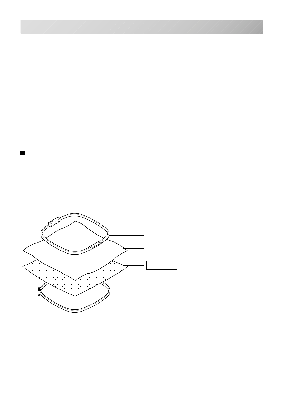
BACKING MATERIALS
4-3
Backing
Generally, Backing is used for hooped embroidery fabric. Knit fabrics particularly require the use
of embroidery backings.
Embroidery backings will allow the hoop to move the fabric more accurately, creating a more
beautiful embroidery.
Select backing type
Choose the thickness and number of sheets by the type of material and embroidery condition.
Generally, you should consider the following items.
•Embroidery stitch quality
•Contraction or compression of fabric caused by sewing, etc.
•Stiffness of fabric
In case, if you sew lace and leather, you may not need backing sheet.
Example of using a backing
Embroidery frame (Inner frame)
Fabric
Backing sheet
Outer frame
-CS -21
4_3 D607
Page 27
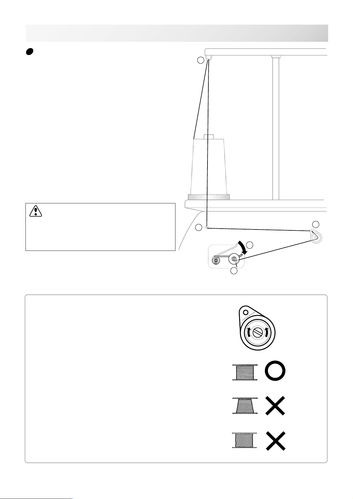
BOBBIN WINDING
Winding the bobbin
Thread the bobbin winder as shown below:
1. Upper Thread guide
2. Thread guide
3. Thread tension – Be sure to thread through the
small eye before going between the disks.
4. Bobbin (Place the bobbin on the bobbin winder
spindle.)
5. Press the limit lever as indicated by the arrow
to start the winder. The lever stops the winder
automatically after the winding is complete.
4-4
1
CAUTION: To prevent accidents.
When lever is pressed down, the bobbin
winder spindle and the bobbin start turning.
Keep fingers and body away until the bobbin
winder stops turning.
Tension
When adjusting bobbin winder tension:
• Ensure thread winds evenly on bobbin as
shown.
Confirm that the bobbin is wound properly..
2
5
4
Increase Decrease
3
• Keep the tension constant while winding.
Tighten thread tension if thread winds too loosely.
-CS -24
4_4 K101
Page 28
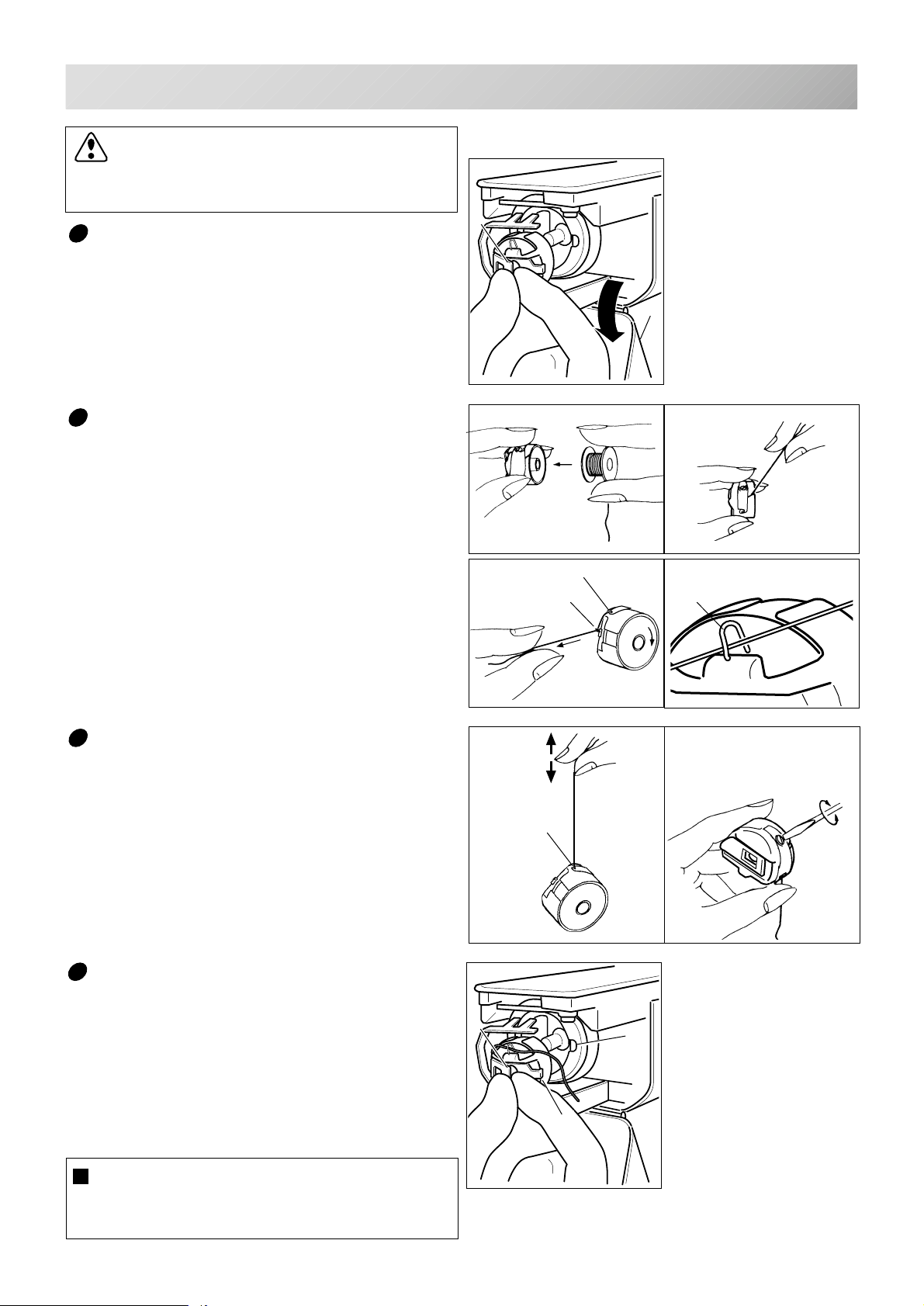
BOBBIN WINDING
CAUTION: To prevent accidents.
Please watch out for the point of the rotary
hook when you replace the bobbin.
4-5
Removing the bobbin
1. Open hook cover (A) to front.
2. Grasp bobbin case latch (B) and withdraw
bobbin case from hook taking care not to
damage the thread keeper.
Inserting the bobbin
1. Hold the bobbin case in left hand. Hold the
bobbin in your right hand with thread on top
leading from left to right.
2. Insert bobbin in case and draw thread up
into slot in case.
3. Draw thread under tension spring (A) and
wind into guide coil (B). The bobbin should
turn clockwise in the case when the thread
is pulled.
B
B
A
A
B
Adjusting bobbin thread tension
1. Hold bobbin thread and jerk upward approx.
an inch. Thread should unspool further
approx. the same amount.
2. The screw on the tension spring is for adjusting bobbin tension. This adjustment is
very delicate. Please turn the screw only a
small amount. Only 1/8 of a turn maximum.
Inserting the bobbin case
1. After threading bobbin in case, open bobbin
case latch (A), grasping it in fingers as
shown.
Slip bobbin and case on stud of rotary hook
body, and press in securely. Release bobbin case latch. Press the bobbin case in to
be sure it is fully seated.
2. Close hook cover.
The attached bobbin case is available only
for this machine. Thread may be caught in
thread guide coil if other types are used.
A
Increase
A
Decrease
C
B
-CD -28
4_5 FA21
Page 29
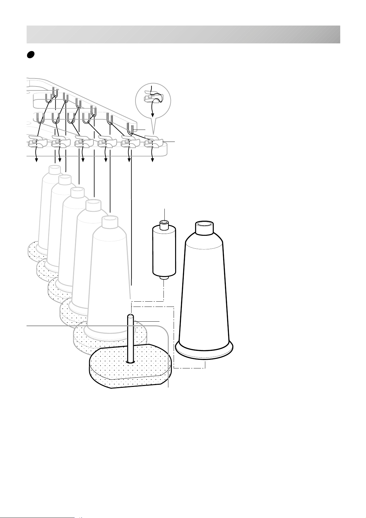
THREADING THE MACHINE
How to thread upper thread
Pass upper threads in order according to the figure:
2
3
Small cone
4-6
1
1. Thread stand
Set thread cone on the stand.
Small cones can also be used as shown.
2. Thread guide
Thread through the thread guide above each
thread cone.
3. Upper rectifier
Continued next page
-CS -24
4_6 AF27
Page 30
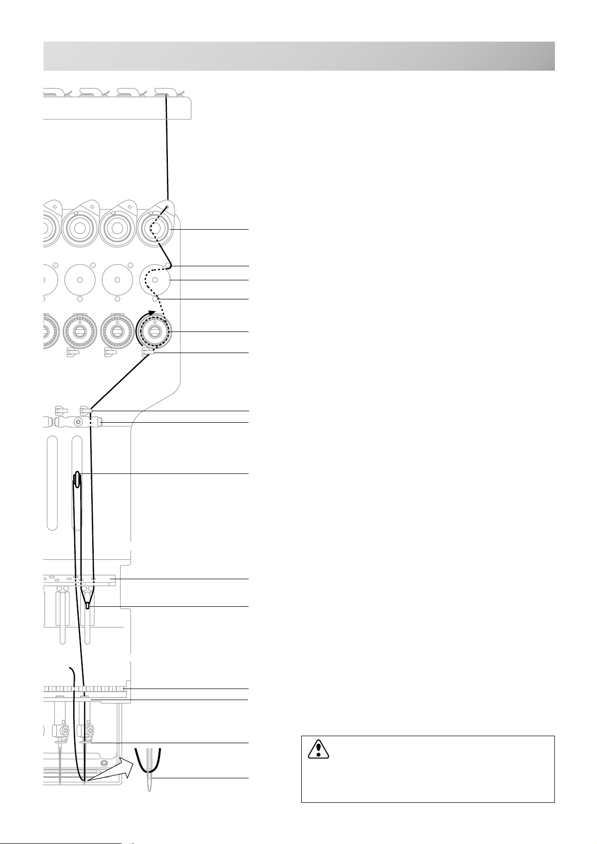
THREADING THE MACHINE
4. Minor thread tension
4-7
4
5
6
7
8
9
10
11
15
5. Guide pin upper
6. Detecting roller
7. Guide pin lower
8. Thread tension
Wind upper threads one time around rotary
tension disc clock-wise.
9. Upper thread guide
10.Lower thread guide
11.Lower rectifier
12.Thread guide plate upper
13.Thread adjusting spring
14.Thread guide plate upper
12,14,16
13
20
17
18
19
15.Take-up lever
16.Thread guide plate upper
17.Thread guide plate lower
18.Needle bar thread guide
19.Needle
Thread from front side of needle.
Pull upper threads slowly and see that the detecting roller moves smoothly by pulling the thread
downward as much as possible.
20.Thread holding spring
Push thread into spring.
CAUTION: To prevent accidents.
Please be careful of the sharp point of the
needles when threading upper threads
through the needle.
-CS -25
4_7 D620
Page 31
P.FOOT T.CUT
MENU
FORWARD
ENT.
P.FOOT T.CUT
MENU
FORWARD
ENT.
P.FOOT T.CUT
MENU
FORWARD
ENT.
P.FOOT T.CUT
MENU
FORWARD
ENT.
MACHINE SETTINGS
5
7
Before embroidering, set the basic settings of the machine.
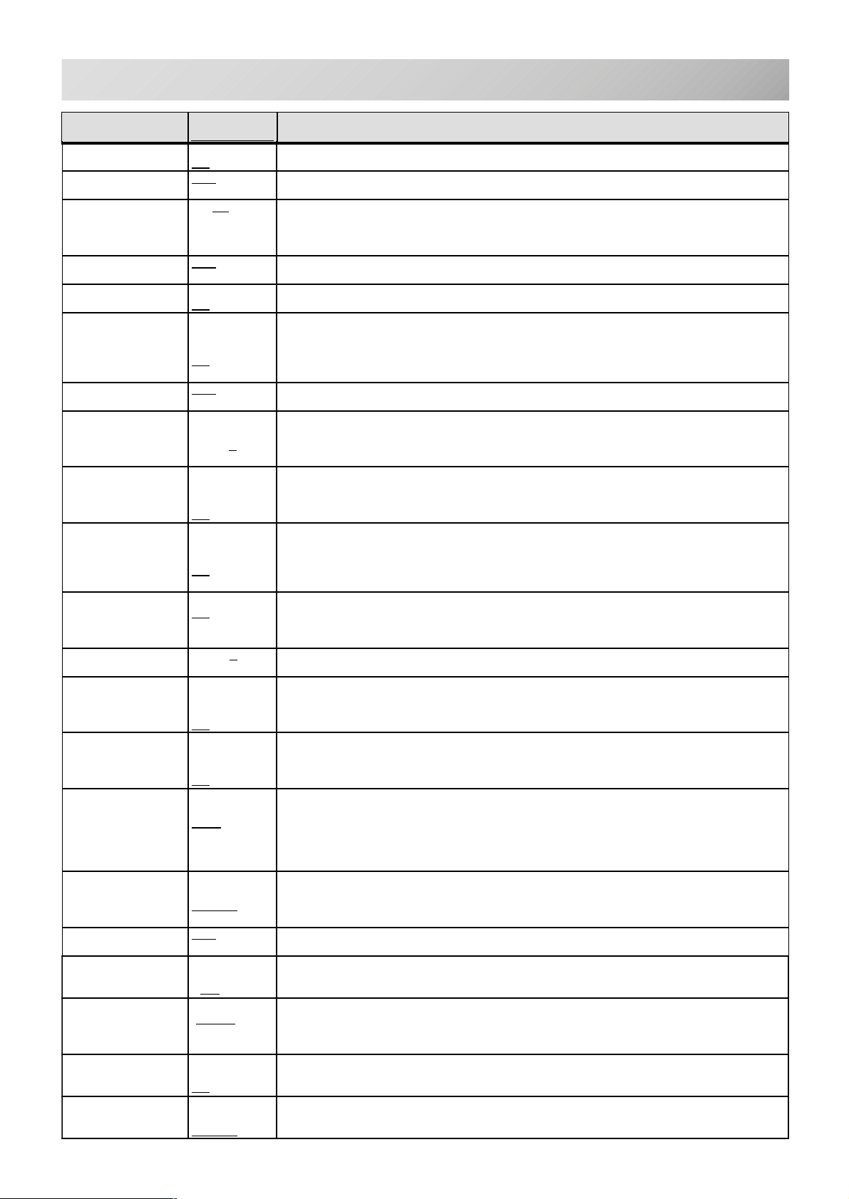
Please set the No. 21 (232C speed) when you connect with the PC.
The rest of the setting should be defaults (indicated by underline) normally.
5-1
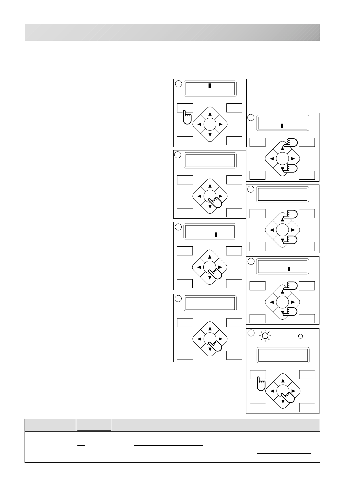
1. Press the "MENU" button until [MENU] is
showing when the machine is stopped.
2. Select "Create" by using the up and down
"Arrow" buttons.
3. Press "ENT." button. The indicator will display a machine setting.
4. Press up and down "Arrow" button until it
comes to the setting you wish to change.
5. Press "ENT." button to display a cursor on
the indicator.
Now you can change the setting.
1
[MENU] Pattern
Needle
3
1 Keep null
(CHG.): No
20 232C speed
: 38400
2
[MENU] F•Posi
Create
MENU
FORWARD
ENT.
P.FOOT T.CUT
4
20 232C speed
: 38400
MENU
FORWARD
ENT.
P.FOOT T.CUT
6. Press up and down "Arrow" button to
choose "YES" , "NO" or other choice as
available.
7. Press "ENT." button to retain this new setting.
If you desire to change other settings, please
repeat the steps 4 through 7 above.
8. Finally, Press the "MENU" button until the
green lamp is showing on the control box.
When the green lamp is glowing, you are in Drive
mode and can begin sewing.
gnitteS
denilrednusitlufiD
seY
oN
seY
oN
stnetnoC
egnahc.atadnrettapgnidaernehw
.atad
yalpsiD.oN
llunpeeK1
).GHC(
llunpikS2
hctits
20 232C speed
: 57600
6
20 232C speed
: 57600
MENU
FORWARD
ENT.
P.FOOT T.CUT
8
G
Nd:12
HAPPY
MENU
FORWARD
ENT.
P.FOOT T.CUT
rolocerofeberayehtsasehctitsorezdaerenihcamehtstelnoitcnufsihT
sehctitsorezehtllagnirongiybatadnrettapsdaersihT nrettapgnidaernehw
-CS -26
5_1 G420
Page 32
MACHINE SETTINGS
5-2
oN
oN
oN
oN
oN
oN
oN ...............
oN
oN
oN
oN
oN
oN
-131
seY
seY
seY
seY
seY
seY
seY
otuA
0.0 .......mm
gnitteS
(8~13
)
(8-04
eniL•O ........
00483
lamroN
denilrednusitlufiD
mm
)7.21=31(
.............seY
...............
.......)
..................0
.............seY
.............seY
...............
)mm8.0-0(
.............seY
...............
.............seY
...............
............
.......ypHjaT
............drB
.............ksZ
............aerA
mm0.1~0.1-
spb00291
spb
spb00675
spb002511
.............seY
...............
MOC-BSU
stnetnoC
.sdaerdnamm7.21fomumixamotpusehctitspmujsuounitnoceht
.spots
.31ottessieulavgnittesnehw
.tpurretniretfaemarfehtdevomsahrotarepofineve
.yllacitamotuangisedruoy)etator(
.mirtdaerht
.pmujerofebsdaerhtstuc
.mirttonseoD•
.atadpmujytpmenomirtseoD•
.atadpmujytpmenomirttonseoD•
.egnahcrolocyrevetamirtasecroF
.egnahcrolocerofebmirtdaerhtsyawlA•
.mirt
.htgnelregnolaotsdaerhtreppustucenihcamehT
gnoL•
dradnatS•
.hctitskcolgnoltceleS
gnoL•
dradnatS•
.atadyrediorbmefotamrofatadtceleS
noitingocercitamotuA•
yppaH,amijaT•
naduraB•
ksZ•
).egaptxenehtno
ngisedehtforetemirepehtdnuoraswollofeniltuO•
erauqsahtiwngisedehtseniltuoaerA•
.yllacitamotuahctitskcolnotuP
.tnuomadetcelesybhtdiwhctitsnitastsujdA•
.htdiwtsujdatonseoD•
yvaeH
dradnatS
.enihcaMeht
."lamroN"ottessititluafedyB•
.tucdaerhtretfaylwolssehctits3otpuswesenihcamehT•
.tucdaerhtretfaylwolssehctits5otpuswesenihcamehT•
.potsdnaegnahcrolocretfatucdaerhtcitamotuasmrofrepsihT
.pmujtnatsnocforebmungnittesnodaerhtehtsmirtenihcaM•
.pmujorezehterofebtucdaerhtasmrofrepsiht,retfaerehtpmuj
.niagangisedyrediorbmeruoydaerdna"seY'otegnahc
."seY"otegnahcesaelp,mirtaretfagniwessmelborpevahuoyfI
.melborpmirtdaerhtevahuoynehw"seY'tcelesesaelP
.tamrofrehtotcelesesaelP,"otuA"nehwrorrenaevahuoyfI
.setarrehgihtarorreroflaitnetopretaergasiereht,revewoH.retsaf
.thgiewlairetamybsdnepedlairetamytudyvaehrofgnittessihT
.yllacitamotuadesaercedsideepsenihcaM
otCPepyttib46htiwnoitcennocBSUekamuoynehwtcelesesaelP•
senibmocsiht,atadnrettapgnidaernehwsehctitspmujgnitaepereraerehtfI
enihcamehtdnasehctitswefakcabseogemarfevirdeht,kaerbsdaerhtnehW
pmujsihtybtisedividenihcameht,htgnelsihtsdeecxehtgnelhctitsnehW
ylnomm7.21semocebtimilatadhtdiW.stnemevomelpitlumsetaercdnahtgnel
.lairetamyvaehdnakcihtesuuoynehwrebmunrellamsaesuesaelP
noitpurretnigniwesretfanoitisopnwestsalotsnruter&srebmemerenihcaM
trevnoclliwenihcameht,enihcamehtnoemarfevirdpacehtllatsniuoynehW
".oN"tcelesesaelP.ylwolsdeepsesaercnilliwenihcameht,"oN"ottesuoyfI
retfahctitsgninnigebehtnosehctitsdeppikshtiwmelborpaevahuoynehw
enihcameht,atadnrettapnistsixespmujsuounitnocforebmuntesanehW
enonahteromdnaatadnrettapehtnipmujorezfohctitsenosierehtnehW
tonseodenihcam,tniopegnahcroloctanoitcnufmirtevahtonseodatadfI•
.atadnrettapgnidaernehwsehctitstrohsylemertxesetanimilenoitcnufsihT
elbissopsiti,emitehtllatniopemasehttamelborpkaerbdaerhtaevahuoyfI
esaelp,esacehtsisihtfI.atadehtnisehctitsetunimsahatadyrediorbmeruoy
.htgnelsihtnahtsselsihtdiwhctitsehtnehwsehctitssetelednoitcnufsihT
noitanalpxedeliatederomehtotreferesaelP(.ecartngisedfoepytehttceleS
.yromemehtnisngisedehtllarofsehctitsnitasllafoshtdiwehtretlaotsisihT
lairess'enihcamehtfo)etarduab(deepsnoitacinummoCehttcelesesaelP
.CPruoysadeepsemasehtotdeepsnoitacinummocehttsujdA.trop
daereblliwngisedehtfoatadeht,tnuomaregralaottessietarduabehtfI
yalpsiD.oN
pmujenibmoC3
kaerb.DRT4
kcab
atadhtdiW5
timil
otuA.RTS6
noitisoP
pactrevnoC7
tratskciuQ8
edom
daerhtotuA9
tuc
pmujtatuC01
atad
lluntatuC11
pmuj
syawla.GHC21
tuc
hctitS31
repeews
htgnelpeewS41
htgnellluF51
tuc
kcolgnoL61
hctits
tamrofataD71
epytecarT81
kcoL.RTS91
hctits
atadhtdiW02
lla
deepsC23212
edomyvaeH22
-inummoCBSU32
noitac
-CS -29
5_2 J801
Page 33
MACHINE SETTINGS
Detailed explanation of machine setting
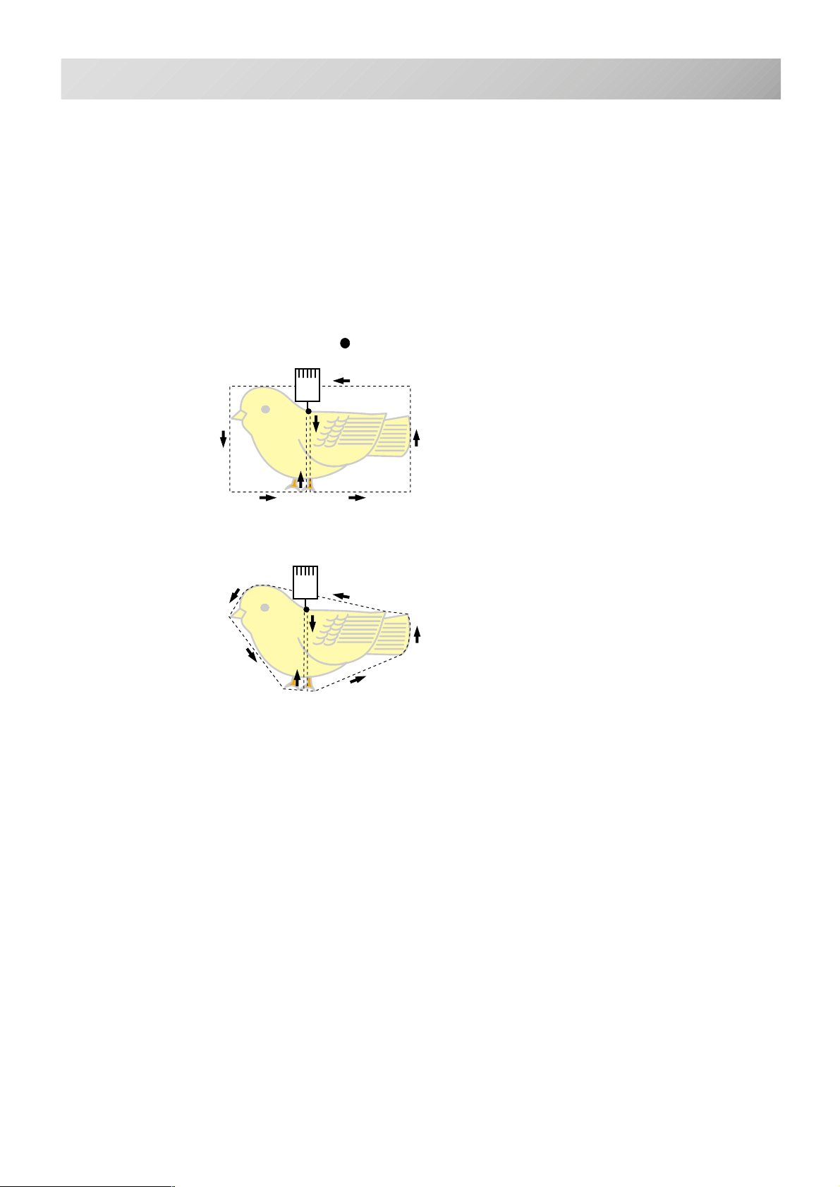
#18 Trace type (Select type of design trace)
You can compare the design size and design
position to the embroidery frame before you
start sewing. The embroidery frame moves
around the actual design size.
At this time you can choose which type of trace
from 2 types of traces like the following figures.
5-3
Area
Outline
: Start point
-CS -28
5_3 D609
Page 34
PREPARATION OF PATTERN DATA
5-4
Connecting to a PC by Serial or USB connection
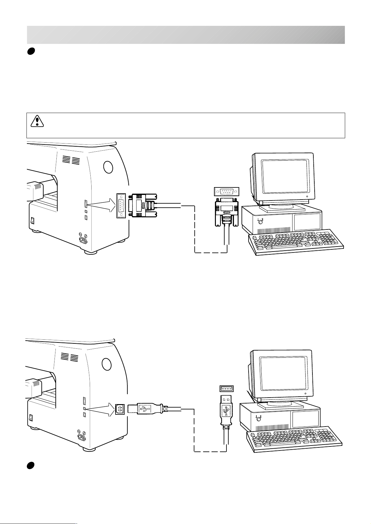
This embroidery machine will allow you to read design data from a connected PC.
A Serial cable or a USB cable can be used for the connection.
Serial connection
Connect the serial cable between the serial port (RS-232C) of the machine and the serial port of
the PC.
CAUTION: To avoid problems.
Make sure that power source of machine and PC are off when connecting serial cable.
Serial port
USB connection (
Connect by USB cable between USB port of the machine and USB port of the PC.
When you connect the USB cable, make sure that the machine is powered and set into drive mode (lamp
will be green), and that the PC is also turned on.
After recognizing USB in your PC, start-up the "Happy Link".
Please refer to instruction book of "Happy Link" for more precise information.
based on the
USB 1.1, 2.0)
RS-232C
USB
USB port
Reading embroidery pattern data from the PC
Designs can be transferred to the machine along with some functions by using the "Happy Link"
software.
Please refer to the “Happy Link” software manual for instructions.
-CS -29
5_4 FA27
Page 35
PREPARATION OF PATTERN DATA
5-5
Read embroidery pattern data from memory media
Read the pattern to be embroidered from the memory media.
These types of memory media can be used. This machine is able to read different kinds of
memory cards, which are generally used for digital cameras.
•Compact flash card
•Smart media card
•Memory stick
•SD card
•USB memory
Capacity of memory media has to be over 16MB. This machine doesn’t correspond if the
capacity of memory media card is under 8MB.
If you initialize the memory media with your PC, please proceed with FAT format form.
Proceed with FAT 32 format in case of memory media is over 1GB.
This machine doesn’t correspond if the memory media is initialized by electrical appliances
(Ex. digital camera) exclude PC.
Note for using Memory Card.
It is possible to use only memory cards (compact flash card, smart media card, memory stick,
SD card) which are inserted into a PCMCIA card adaptor.
If you insert a LAN card or PCMCIA card other than noted above, it is possible the machine
will break down.
Handling note of Memory Cards and USB memory.
Do not bend, drop, disassemble, charge or heat the memory card and USB memory.
Keep away from humidity or direct sunlight.
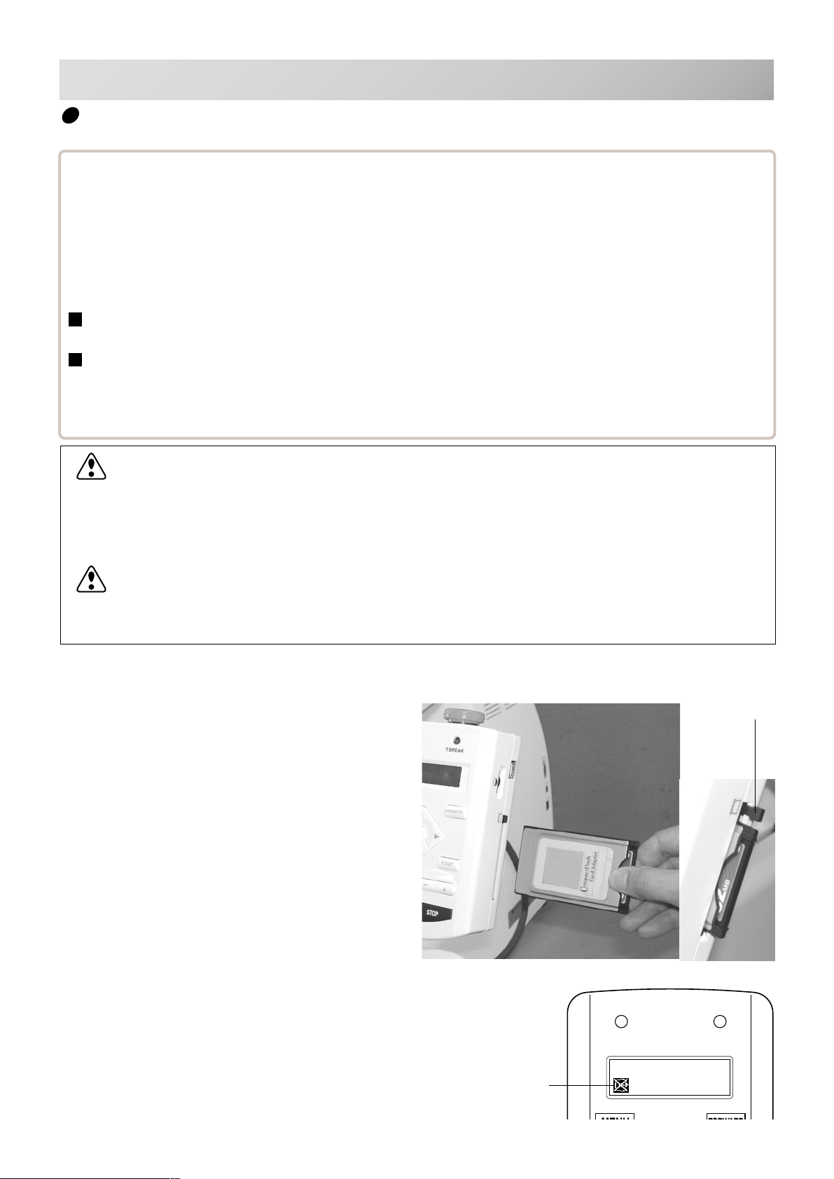
To insert a memory card
1. Insert the memory card that contains the
design data into its PCMCIA card adaptor.
(You must provide the PCMCIA card adaptor for your particular memory card).
2. Insert the PCMCIA card adapter all the way
into the Memory card slot of the machine
(right side of controller).
(The memory card should face toward you.)
The Eject button will come out.
3. Read embroidery design data according to
following “Memory card reading” in the next
section.
Eject Button
To remove a memory card
1. Please check that the “Do Not Remove”
icon is not shown. Then push the eject
button.
Pull memory card and adapter all the way out.
2. Please handle memory card carefully.
Do Not Remove
memory media
-CS -32
5_5 H701
Page 36
PREPARATION OF PATTERN DATA
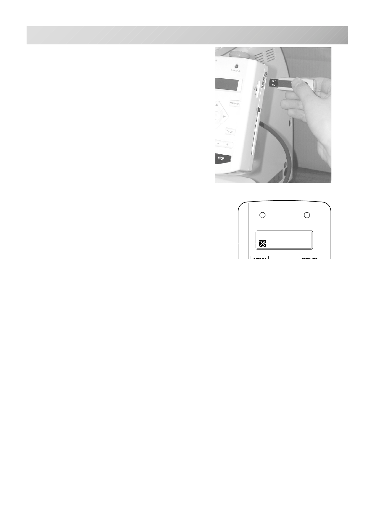
To insert a USB memory
1. Insert the USB memory all the way into the
USB memory port of the machine (right side
of controller).
2. Read embroidery design data according to
following “Memory card reading” in the next
section.
To remove a USB memory
1. Please check that the “Do Not Remove”
icon is not shown.
2. Please handle USB memory carefully.
5-5b
Do Not Remove
memory media
5_5 H701
-CS -33
Page 37
PREPARATION OF PATTERN DATA
FORWARD
P.FOOT T.CUT
MENU
ENT.
FORWARD
P.FOOT T.CUT
MENU
ENT.
FORWARD
P.FOOT T.CUT
MENU
ENT.
FORWARD
P.FOOT T.CUT
MENU
ENT.
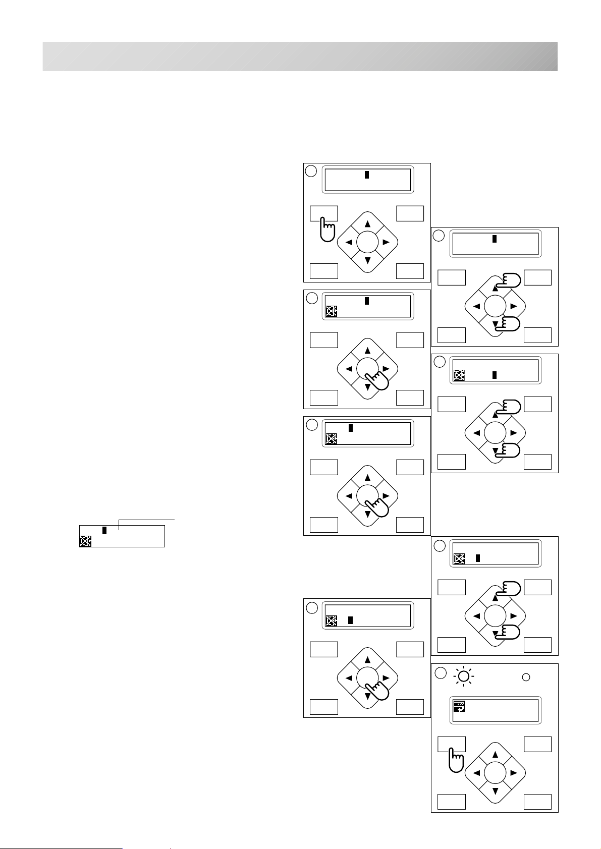
Memory media reading
1. Please insert the memory media into the
machine as related in the “To insert a
memory media” section above.
5-6
2. Press the "MENU" button until [MENU] is
shown while the machine is stopped.
3. Press the “Up” or “Down” arrow button until
the cursor points to “Read”.
4. Press the "ENT." button.
Section for select of memory card reading and
USB memory reading.
5. Press up and down "Arrow" button to
choose "Card" or "USB".
6. Press the "ENT." button.
The display will show a design name.
A folder is shown when "◆" is displayed on the
right of the name.
The inside of a folder will be displayed, if this is
chosen and an ENT. button is pushed.
Displaying design name in
[RD] ..
PLANT
A display of the inside of a folder will display
".. ◆" at a head.
Select ".. ◆" and press ENT. key for will return
out of a folder.
Moreover, if a menu button is pushed even if it
does not choose this ".. ◆", it will return out of a
folder.
the folder is shown.
◆
◆
2
[MENU] Pattern
Needle
4
[READ] Read
USB
6
[RD] ANIMAL
FANTASIA
8
[RD] ANIMAL
FANTASIA
3
[MENU] Read
Convert
MENU
FORWARD
ENT.
P.FOOT T.CUT
5
[READ] Card
USB
MENU
◆
ENT.
FORWARD
P.FOOT T.CUT
7
[RD] ANIMAL
FANTASIA
MENU
◆
ENT.
◆
FORWARD
7. Press the “Up” or “Down" arrow button to
choose the embroidery pattern.
8. Press the "ENT." button.
Once design is read, enable to read next design
continuously.
If you wish to read another design, continue to
follow the items in step 7.
9. Press the "MENU" button.
Enable to move off from the folder (".. ◆" is in a
head.) or enable to move back to drive mode
(There is no ".. ◆" in a head.).
P.FOOT T.CUT
9
G
ID:14 Nd: 6
FANTASIA
MENU
FORWARD
ENT.
P.FOOT T.CUT
-CS -34
5_6 H701
Page 38
PREPARATION OF PATTERN DATA
FORWARD
P.FOOT T.CUT
MENU
ENT.
FORWARD
P.FOOT T.CUT
MENU
ENT.
FORWARD
P.FOOT T.CUT
MENU
ENT.
FORWARD
P.FOOT T.CUT
MENU
ENT.
7
1
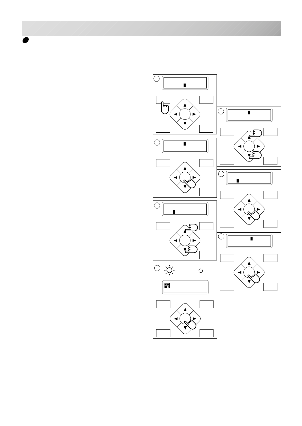
Select an embroidery pattern from memory
To select an embroidery design previously
stored into the machine memory.
5-7
1. Press the "MENU" button until [MENU] is
shown when the machine is stopped.
2. Press the “Up” or “Down” Arrow button until
the cursor points to "Pattern".
3. Press "ENT." button.
The cursor will be on "Select".
4. Press the "ENT." button when showing
[Select].
The Upper line indicates the current pattern ID
number (if any).
The Lower line indicates the pattern name and
ID number of a pattern you can select.
5. Press the “Up” and “Down” Arrow button to
choose the embroidery pattern.
[MENU] Pattern
Needle
3
[PAT.] Select
Erase
5
[SELECT](ID:10)
14 FANTASIA
2
[MENU] Pattern
Needle
MENU
FORWARD
ENT.
P.FOOT T.CUT
4
[SELECT](ID:10)
10 CAT
MENU
FORWARD
ENT.
P.FOOT T.CUT
6. Press the "ENT." button.
The display will show ”OK” or ”Cancel”.
7. Press the "ENT." button.
Make your selection and return to drive mode.
Press the ”Down” Arrow button then press
the "ENT." button to cancel selecting a
design from the memory.
G
ID:14 Nd: 6
FANTASIA
6
[SELECT] OK
Cancel
MENU
FORWARD
ENT.
P.FOOT T.CUT
-CS -32
5_7 D610
Page 39
PREPARATION OF PATTERN DATA
FORWARD
P.FOOT T.CUT
MENU
ENT.
FORWARD
P.FOOT T.CUT
MENU
ENT.
1
FORWARD
P.FOOT T.CUT
MENU
ENT.
FORWARD
P.FOOT T.CUT
MENU
ENT.
FORWARD
P.FOOT T.CUT
MENU
ENT.
FORWARD
P.FOOT T.CUT
MENU
ENT.
FORWARD
P.FOOT T.CUT
MENU
ENT.
FORWARD
P.FOOT T.CUT
MENU
ENT.
FORWARD
P.FOOT T.CUT
MENU
ENT.
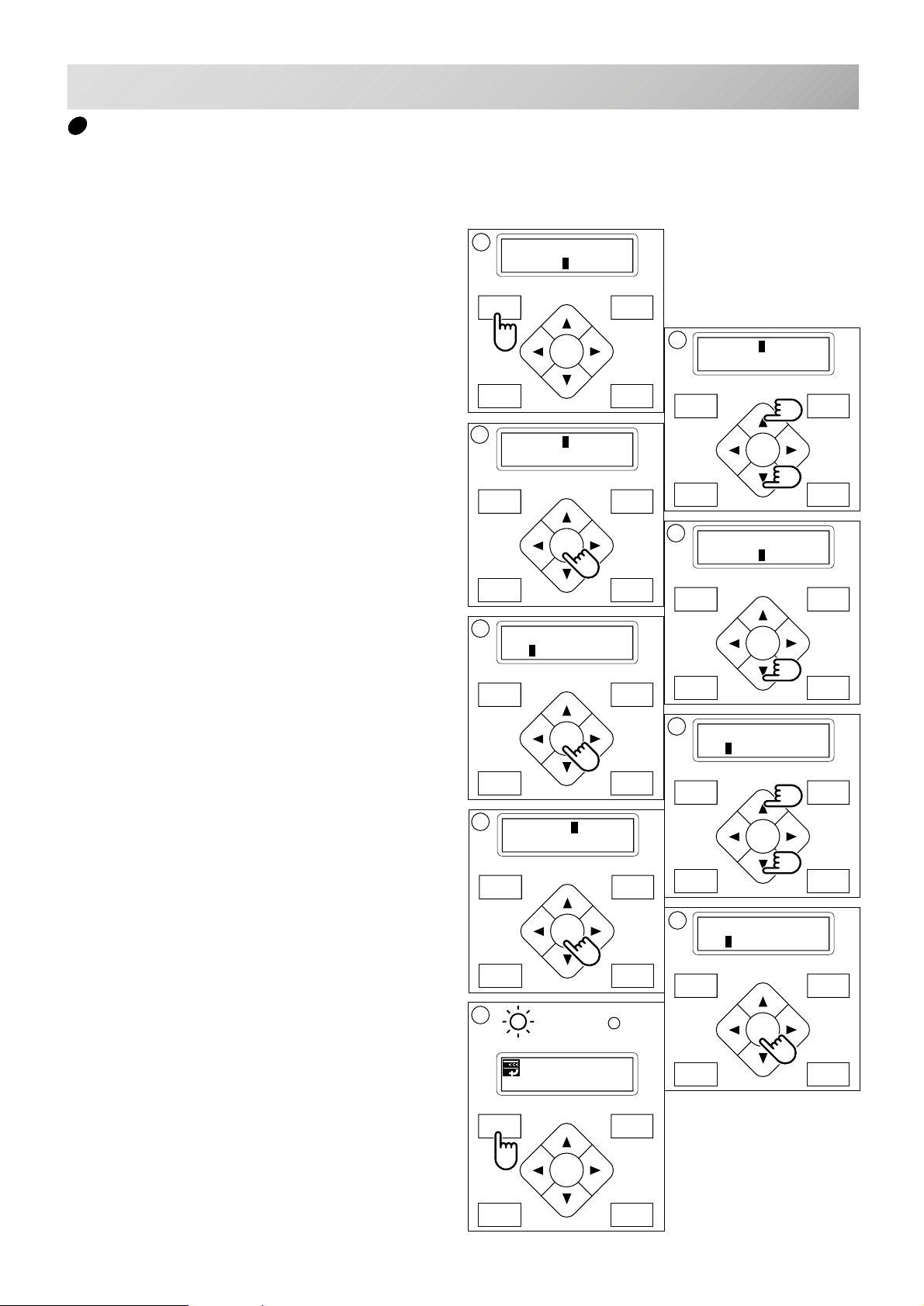
Erase memorized pattern from memory
This is to erase an unnecessary design data from the machine memory.
5-8
1. Press the "MENU" button until [MENU] is
showing when machine is stopped.
2. Press the “Up” or “Down” arrow button until
the cursor points to "Pattern".
3. Press the "ENT." button.
The display will show ”select” or ”Erase”.
4. Press the “Down” Arrow button until the
cursor points to "Erase".
5. Press the "ENT." button when showing
[ERASE].
The display will show the ID no. and the name of
the current design.
[MENU] Pattern
Needle
3
[PAT.] Select
Erase
5
[ERASE] (ID:10)
4 CAT
2
[MENU] Pattern
Needle
4
[PAT.] Select
Erase
6. Press the “Up” or “Down” Arrow button to
choose the embroidery pattern you wish to
delete.
7. Press the "ENT. button".
The display will show ”OK” or ”Cancel”.
8. Press the "ENT. button".
To delete the design and go back to procedure
#6.
Push the “Down” arrow button and "ENT."
button to cancel deleting of the design.
Return to the drive mode.
9. Finally, Press "MENU" button until the
green lamp on the control box glows.
When a green light is showing, It means you are
in the Drive mode and you can start sewing.
7
[ERASE] OK
Cancel
9
G
ID:10 Nd: 4
BIRD
6
[ERASE] (ID:10)
14 FANTASIA
8
[ERASE] (ID:10)
15 BIRD
-CS -33
5_8 D610
Page 40
PREPARATION OF PATTERN DATA
FORWARD
P.FOOT T.CUT
MENU
ENT.
1
FORWARD
P.FOOT T.CUT
MENU
ENT.
FORWARD
P.FOOT T.CUT
MENU
ENT.
FORWARD
P.FOOT T.CUT
MENU
ENT.
FORWARD
P.FOOT T.CUT
MENU
ENT.
FORWARD
P.FOOT T.CUT
MENU
ENT.
FORWARD
P.FOOT T.CUT
MENU
ENT.
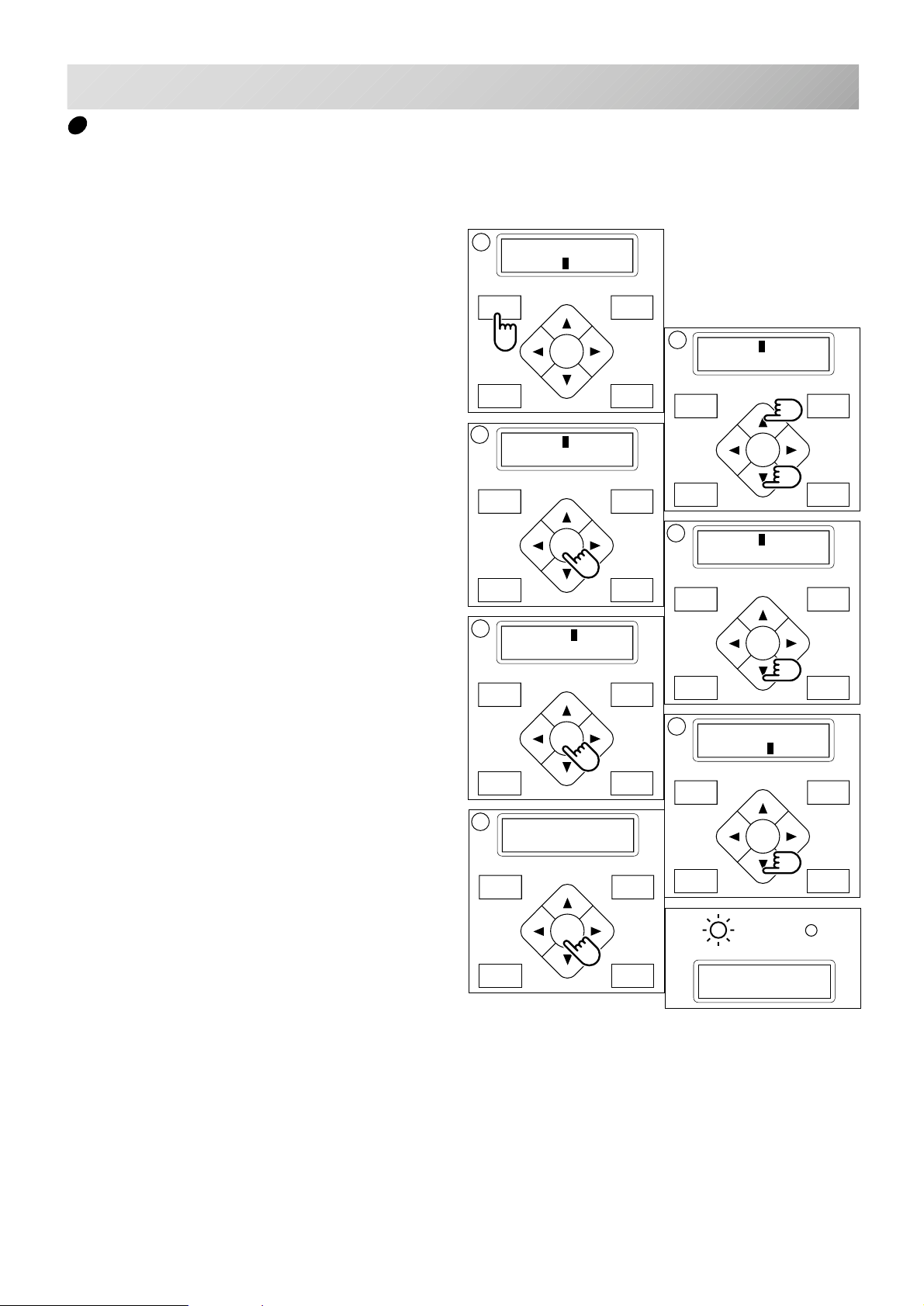
Erase all designs
This is to erase all designs from the machine memory.
5-9
1. Press "MENU" button until [MENU] is showing while the machine is stopped.
2. Press the "Up” or “Down” arrow button until
the cursor points to "Pattern".
3. Press the "ENT." button.
To “Select” or “Erase” the design.
4. Press the “Down” arrow until the cursor
points to "All clr".
5. Press the "ENT." button when showing
[CLEAR].
[MENU] Pattern
Needle
3
[PAT.] Select
Erase
5
[CLEAR] Cancel
OK
2
[MENU] Pattern
Needle
4
[PAT.] All clr
6. Press the “Down” arrow button until the
cursor points to "OK".
7. Press the "ENT." button.
You will then return to drive mode.
Push the “Up” arrow button and then push
the "ENT." button to cancel.
Returns to Drive mode after cancelation of
design delete.
7
-- Complete --
6
[CLEAR] Cancel
OK
G
Nd:14
HAPPY
-CS -34
5_9 D610
Page 41
PREPARATION OF PATTERN DATA
FORWARD
P.FOOT T.CUT
MENU
ENT.
FORWARD
P.FOOT T.CUT
MENU
ENT.
FORWARD
P.FOOT T.CUT
MENU
ENT.
1
FORWARD
P.FOOT T.CUT
MENU
ENT.
FORWARD
P.FOOT T.CUT
MENU
ENT.
9
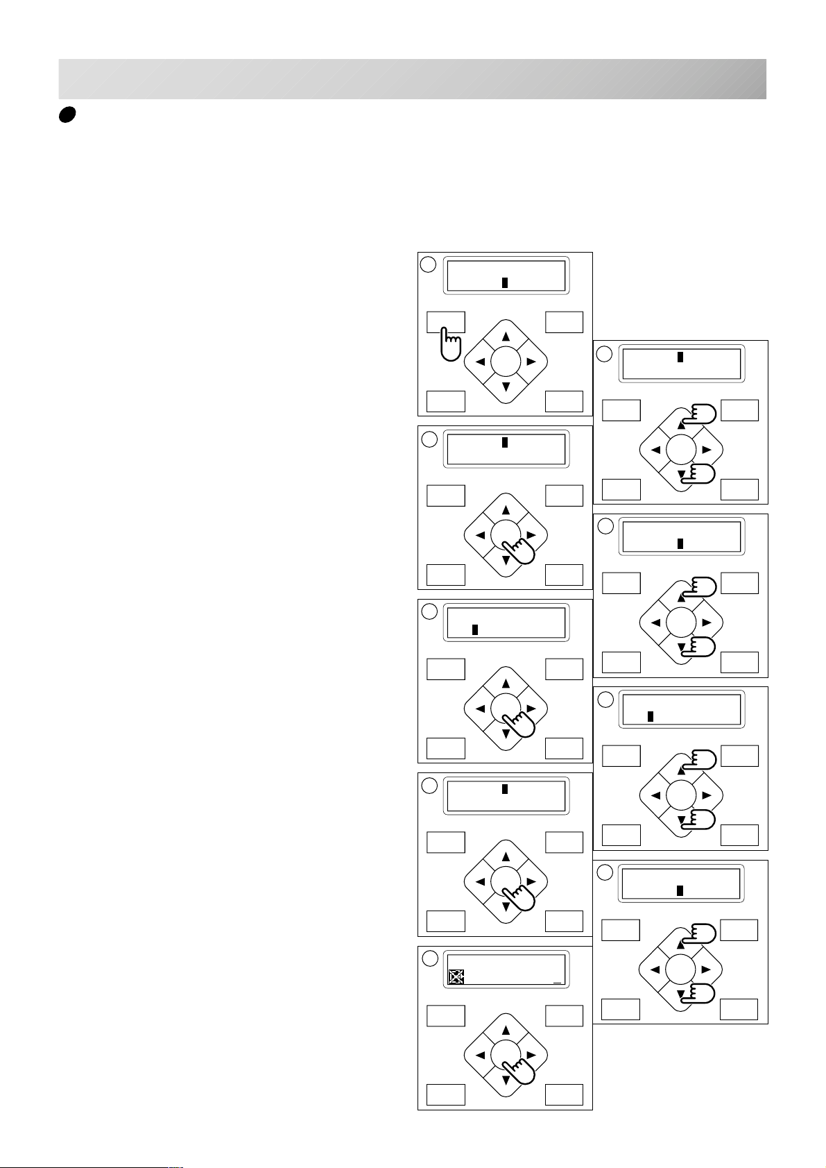
Export memorized pattern from memory
You can write out of machine memory to a memory media.
5-9b
1. Press the "MENU" button until [MENU] is
showing when machine is stopped.
2. Press the “Up” or “Down” arrow button until
the cursor points to "Pattern".
3. Press the "ENT." button.
4. Press the “Down” Arrow button until the
cursor points to "Write".
5. Press the "ENT." button when showing
[WRITE].
The display will show the ID no. and the name of
the current design.
[MENU] Pattern
Needle
3
[PAT.] Select
Erase
5
[WRITE] (ID:10)
10 CAT
2
[MENU] Pattern
Needle
MENU
FORWARD
ENT.
P.FOOT T.CUT
4
[PAT.] All clr
Write
MENU
FORWARD
ENT.
P.FOOT T.CUT
6. Press the “Up” or “Down” Arrow button to
choose the embroidery pattern you wish to
write.
7. Press the "ENT. button".
Section for select of memory card reading and
USB memory reading.
8. Press up and down "Arrow" button to
choose "Card" or "USB".
9. Press the "ENT. button".
After displaying it as "Writing data-" , showing
design name and letter pallet on top of line and
lower line of the display.
7
[WRITE] Card
USB
Name:FLOWER_
0123456789 -!
6
[WRITE] (ID:10)
14 FLOWER
MENU
FORWARD
ENT.
P.FOOT T.CUT
8
[WRITE] Card
USB
MENU
FORWARD
ENT.
P.FOOT T.CUT
-CS -38
5_9b H701
Page 42
PREPARATION OF PATTERN DATA
FORWARD
P.FOOT T.CUT
MENU
ENT.
FORWARD
P.FOOT T.CUT
MENU
ENT.
FORWARD
P.FOOT T.CUT
MENU
ENT.
-
+
FORWARD
P.FOOT T.CUT
MENU
ENT.
5-9c
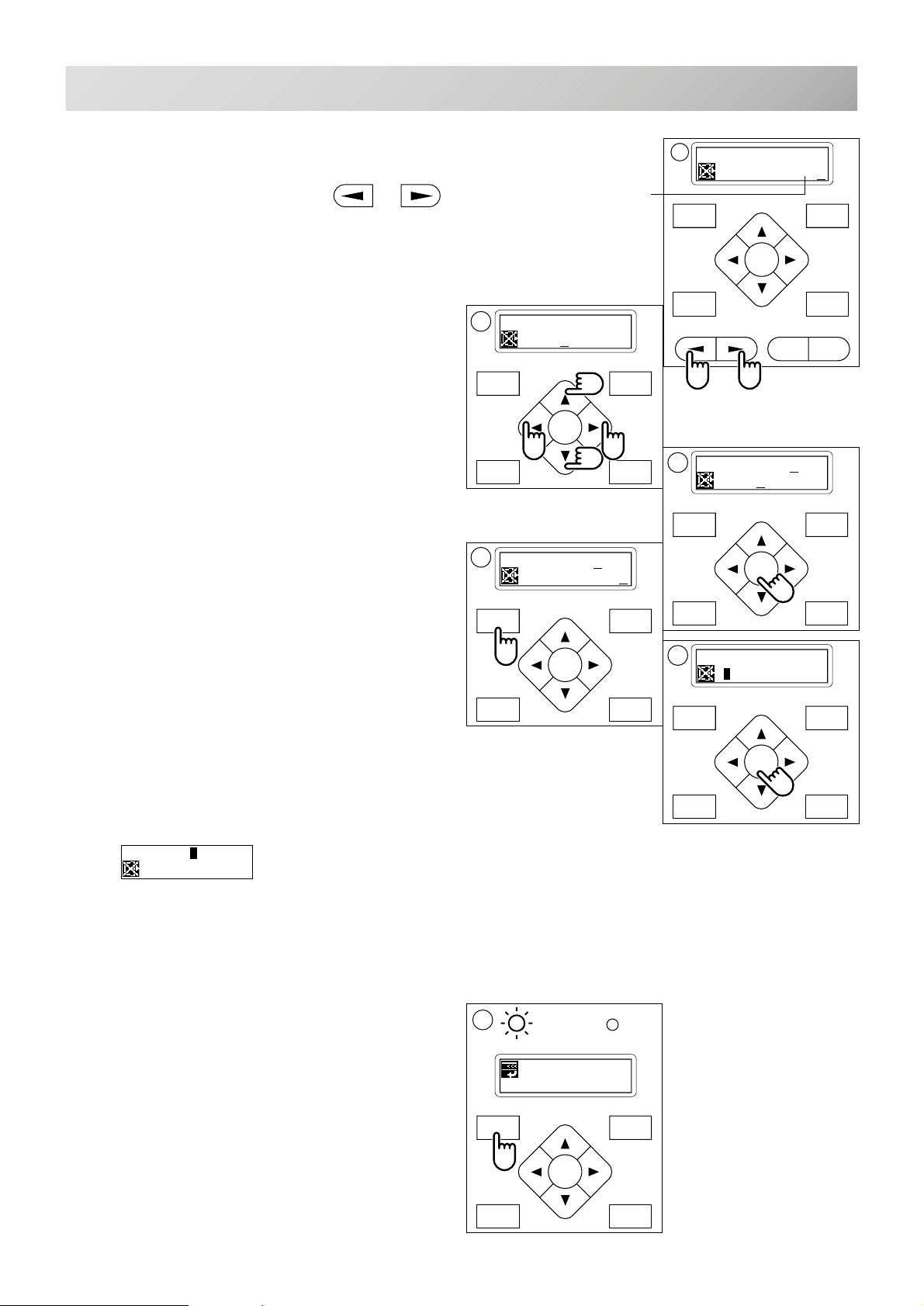
10.When not changing a design name, it
progresses to operation of step #14..
For changing a design name, or
of a needle change button is pushed, and
the beam to change is chosen.
11.The arrow button of the right or the left is
pushed, the cursor of a character palette is
moved, and a character is chosen.
If the arrow button of a top or the bottom is
pushed, letter pallet will change.
12.Press the "ENT. button".
The character chosen by letter pallet is inputted
into a design name.
The maximum number of characters in a design
name is eight letters or numbers.
13.Operation of 10. to 12. is repeated, and a
menu button will be pushed if a design
name is changed.
Or of letter pallet "!" (decision) is chosen.
14.Press the "ENT. button".
After displaying it as ÅgWriting data-Åg,
the beginning is ended and it will be in the state
of choosing other design data.
When writing out other design data continuously,
it progresses to the procedure of 6.
It is as follows when the same name is in
the memory media writing out handle data.
It is displayed.
If a space is chosen,
the character of the cursor of
a handle name will be deleted.
11
Name:FLOWER_
NOPQRSTUVWXYZ
13
Name:FLOWERS
0123456789 -!
10
Name:FLOWER_
0123456789 -!
12
Name:FLOWERS
NOPQRSTUVWXYZ
MENU
FORWARD
ENT.
P.FOOT T.CUT
14
[WRITE] (ID:10)
14 FLOWER
MENU
FORWARD
ENT.
P.FOOT T.CUT
[WRITE] Rename
Same! OK
When overwriting, a lower arrow button is
pushed, cursor is united with "O.K." and
an execution button is pushed.
When changing a design name, an execution
button is pushed and it progresses to operation
of 10.
15.Finally, Press "MENU" button until the green
lamp on the control box glows.
When a green light is showing, It means you are
in the Drive mode and you can start sewing.
15
G
ID:18 Nd: 4
BIRD
-CS -39
5_9c H701
Page 43
PREPARATION OF PATTERN DATA
FORWARD
P.FOOT T.CUT
MENU
ENT.
-
+
P.FOOT T.CUT
MENU
FORWARD
ENT.
P.FOOT T.CUT
MENU
FORWARD
ENT.
P.FOOT T.CUT
MENU
FORWARD
ENT.
-
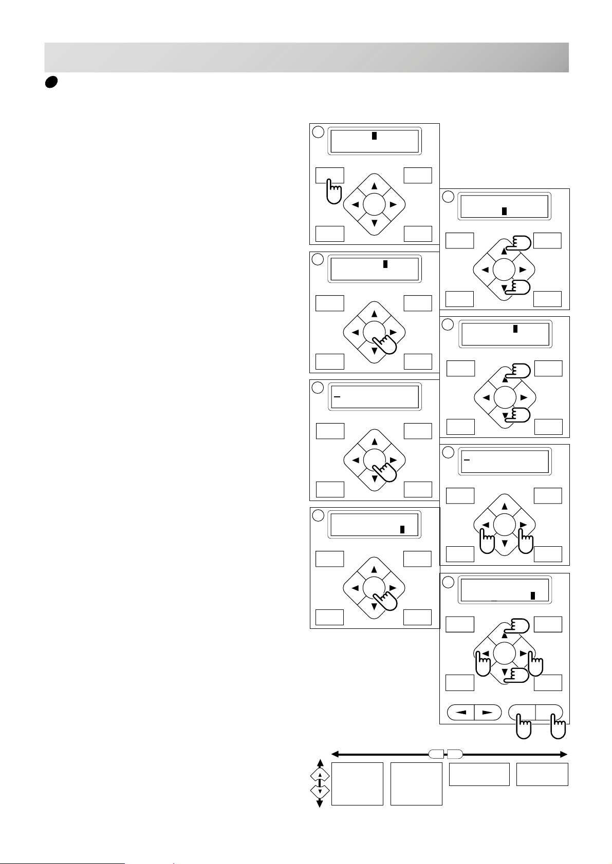
How to select monogram letters
Selecting letters using the built-in fonts.
5-10
1. Press the "MENU" button until [MENU] is
showing when the machine is stopped.
2. Press the “Up” or “Down” arrow button until
the cursor points to "Letter".
3. Press the "ENT." button when showing
[LETTER].
Letter selection (Char)
To select letters. (15 letters maximum)
4. Press the “Up” or “Down” arrow button until
the cursor points to "Char".
5. Press the "ENT." button.
The cursor will move to the left side of the
display.
1
[MENU] Pattern
Needle
MENU
FORWARD
ENT.
P.FOOT T.CUT
3
[LETTER] Char
Area
MENU
FORWARD
ENT.
P.FOOT T.CUT
5
2
[MENU] Create
Letter
MENU
FORWARD
ENT.
P.FOOT T.CUT
4
[LETTER] Char
Area
6. Press the “Left” or Right" arrow button to
select the position of the letter.
7. Press the "ENT." button.
The capital letters “ABCDEF” will be shown.
8. The cursor can move left or right and the
selected letter will be indicated on the right
side of the display.
You can change to the next group of letters
by pressing the “Up” or “Down arrow" button.
Pressing the "+" button will change as the
letters from capital to small letters to numbers to symbols.
Pressing the "-" button reverses the selections.
If you press the ”MENU” or ”STOP” button, you
will return to item 6 above.
7
ABCDEF A
MENU
FORWARD
ENT.
P.FOOT T.CUT
ABCDEF
GHIJKL
MNOPQRS
TUVWXYZ
abcdef
ghijkl
mnopqrs
tuvwxyz
6
8
ABCDEF F
+
0123456789 -,.’/?!
&<>()_
-CS -35
5_10 D610
Page 44
P.FOOT T.CUT
MENU
FORWARD
ENT.
P.FOOT T.CUT
MENU
FORWARD
ENT.
P.FOOT T.CUT
MENU
FORWARD
ENT.
PREPARATION OF PATTERN DATA
5-11
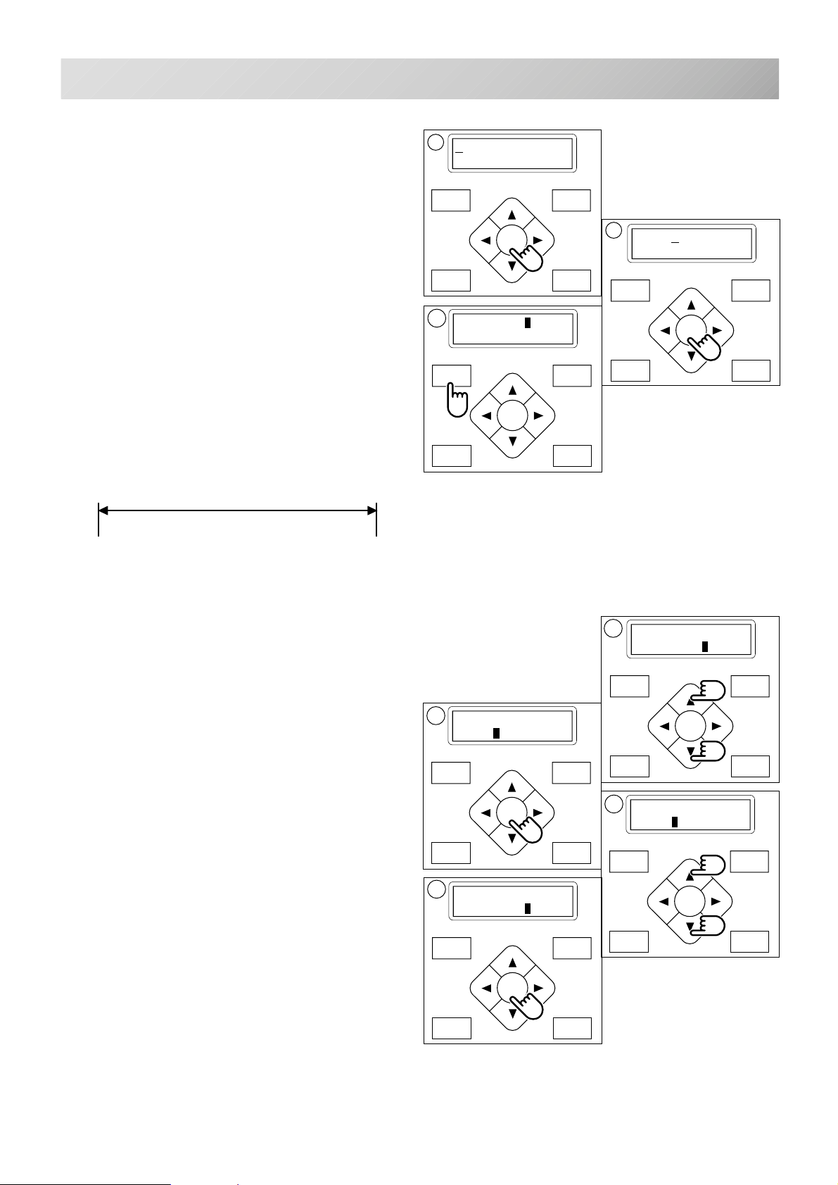
9. Press the "ENT." Button to select the indicated letter, number or symbol.
The cursor will move to the upper line.
10.Repeat the procedure 6. thorough 9 above.
to select additional letters.
If you wish to insert a Space it will not be recognized as a letter.
11.Press the "MENU" button when you are
finished with the letter selection.
The display will show [LETTER].
Line Length (Area)
Enables you to change the line length.
Area : 0 to 290 mm (the maximum hoop size)
Area
9
F
11
[LETTER] Char
Area
MENU
ENT.
P.FOOT T.CUT
FORWARD
10
FLOWER
MENU
ENT.
P.FOOT T.CUT
FORWARD
FLOWER
12.Select "Area" by use of the “up and down"
arrow button.
13.Press the "ENT." button.
14.The size will increase by pressing the “Up”
arrow button.
The size will decrease by pressing the
“Down” arrow button.
Holding down the button for more than 10 numbers will start.
Them increasing (or decreasing) by 10 numbers
at a time.
15.Press the "ENT." button.
Back to procedure 12.
13
FLOWER
Area: 0
15
[LETTER] Char
Area
MENU
ENT.
FORWARD
12
[LETTER] Char
Area
14
FLOWER
Area: 80
MENU
ENT.
P.FOOT T.CUT
FORWARD
P.FOOT T.CUT
-CS -36
5_11 D610
Page 45
P.FOOT T.CUT
MENU
FORWARD
ENT.
P.FOOT T.CUT
MENU
FORWARD
ENT.
P.FOOT T.CUT
MENU
FORWARD
ENT.
P.FOOT T.CUT
MENU
FORWARD
ENT.
P.FOOT T.CUT
MENU
FORWARD
ENT.
P.FOOT T.CUT
MENU
FORWARD
ENT.
PREPARATION OF PATTERN DATA
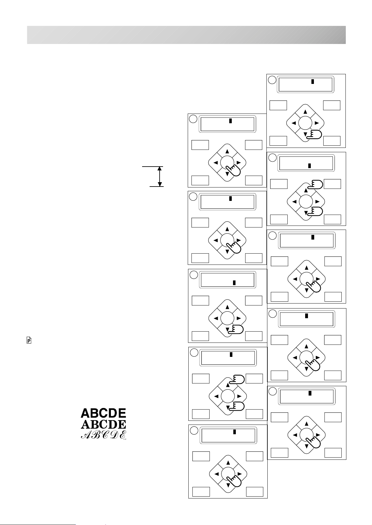
Letter Height selection (Size)
To select the letter size from Large , Middle or
Small.
The letters can be set to one of 3 sizes.
16.Select "Size" by use of the “Down" arrow
button.
5-12
16
[LETTER] Size
Style
MENU
FORWARD
17.Press the "ENT." button when showing
[SIZE].
18.Press the “Up or “Down" arrow button to
select the size of the letter.
Size
A
Large : 15 mm height
Middle : 10 mm height
Small : 4 mm height
19.Press the "ENT." button.
20.Press "ENT." button.
Make your selection and return to procedure 16.
If you want to cancel this procedure, put the
cursor on "Cancel" and push the "ENT."
button.
The status will be back to item #16 above.
17
[SIZE] Large
Middle
19
[SIZE] OK
Cancel
21
[LETTER] Size
Style
MENU
FORWARD
ENT.
P.FOOT T.CUT
18
[SIZE] Large
Middle
MENU
ENT.
P.FOOT T.CUT
20
[LETTER] Size
Style
FORWARD
Font Selection (Style)
Enables you to select the preferred font.
Selections are: Style 1, Style 2, or Style 3.
12-3
21.Select "Style" by use of the “Down" arrow
button.
22.Press the "ENT." button when the display
shows [STYLE].
23.Select fonts by using the ”Up” and “Down”
Arrow buttons.
Style 1 :
Style 2 :
Style 3 :
24.Press the "ENT." button.
25.Press the "ENT." button.
Make your selection and return to procedure 21.
If you want to cancel this procedure, put the
cursor on "Cancel" and push the "ENT."
button.
The status will be back to item #21 above.
ENT.
P.FOOT T.CUT
23
[STYLE] Style1
Style2
25
[LETTER] Size
Style
22
[STYLE] Style1
Style2
MENU
ENT.
P.FOOT T.CUT
24
[STYLE] OK
Cancel
5_12 D610
FORWARD
-CS -37
Page 46
PREPARATION OF PATTERN DATA
P.FOOT T.CUT
MENU
FORWARD
ENT.
P.FOOT T.CUT
MENU
FORWARD
ENT.
P.FOOT T.CUT
MENU
FORWARD
ENT.
P.FOOT T.CUT
MENU
FORWARD
ENT.
P.FOOT T.CUT
MENU
FORWARD
ENT.
P.FOOT T.CUT
MENU
FORWARD
ENT.
P.FOOT T.CUT
MENU
FORWARD
ENT.
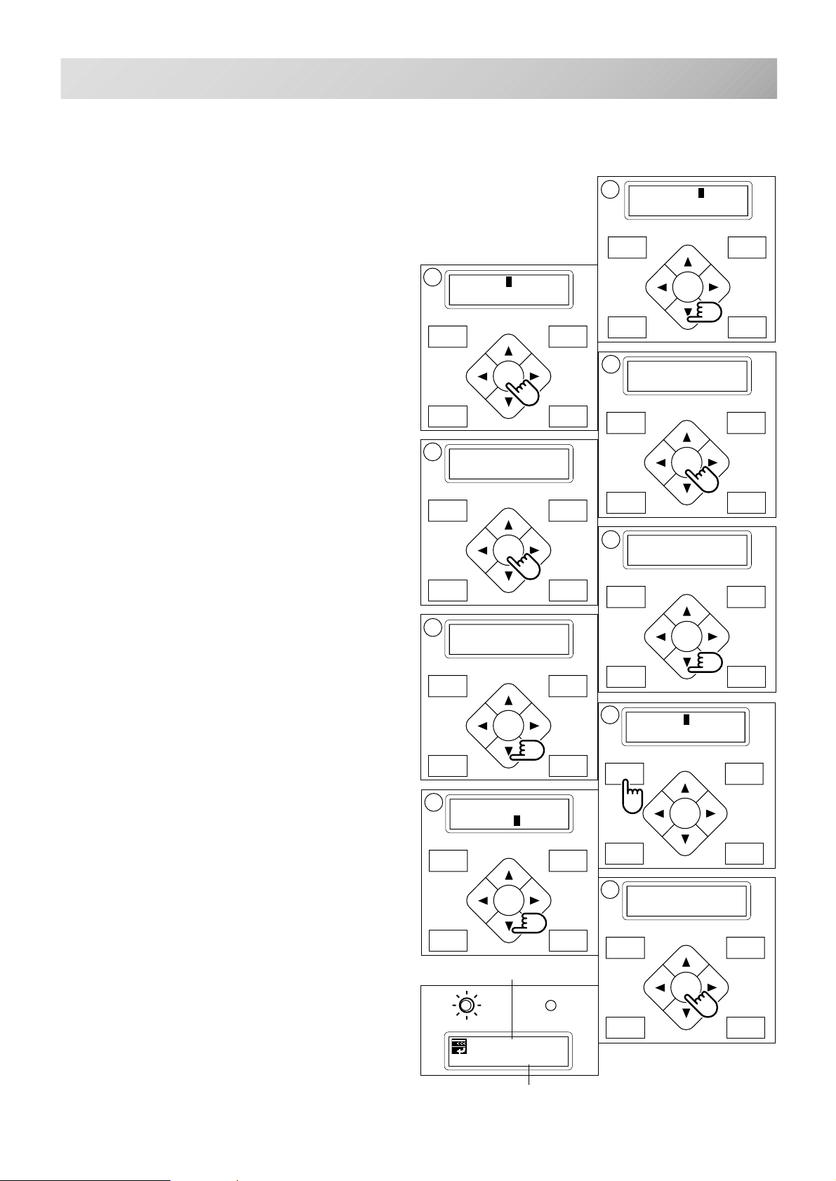
Review mode (Mode)
Enables the user to review the details of their
letter selections, the line length selection, letter
size selection, and font selection.
Also, you can create embroidery data from the
letter settings.
26.Select “Mode” by pressing the “Down” arrow
button.
27.Press the “ENT.” button.
To select “Refer” or "On".
Select (Refer)
28.By pressing the “ENT.” button on [REFER]
will display the letter(s) which you have
selected.
27
[MODE] Refere
On
29
[REFERE]
Area: 80
26
[LETTER] Mode
28
[REFER] Char:
FLOWER
5-13
29.By pressing the “Down” arrow button will
display the number which you have selected
as line length.
30.Pressing the “Down” arrow button again will
display the letter size selection.
31.Pressing the “Down” arrow button again will
display the font Selection.
To complete your letter selections.
32.Press the “MENU” button.
Select review mode “On”
To convert the Letters into an embroidery design.
33.Select “On” by use of the “Down” arrow
button.
34.Press the “ENT.” button.
“NOW LOADING •••” will appear and the new
pattern data will be created. Then you will return
to drive mode.
The first 8 letters will be shown as the name of
the pattern which you have made by letter selection.
31
[REFERE]
Style:Style1
33
[MODE] Refer
On
MENU
FORWARD
ENT.
P.FOOT T.CUT
New pattern number
G
ID:15 Nd: 3
FLOWER
30
[REFERE]
Size:Middle
32
[MODE] Refere
On
34
NOW LOADING•••
MENU
FORWARD
ENT.
P.FOOT T.CUT
New pattern name
-CS -38
5_13 D610
Page 47
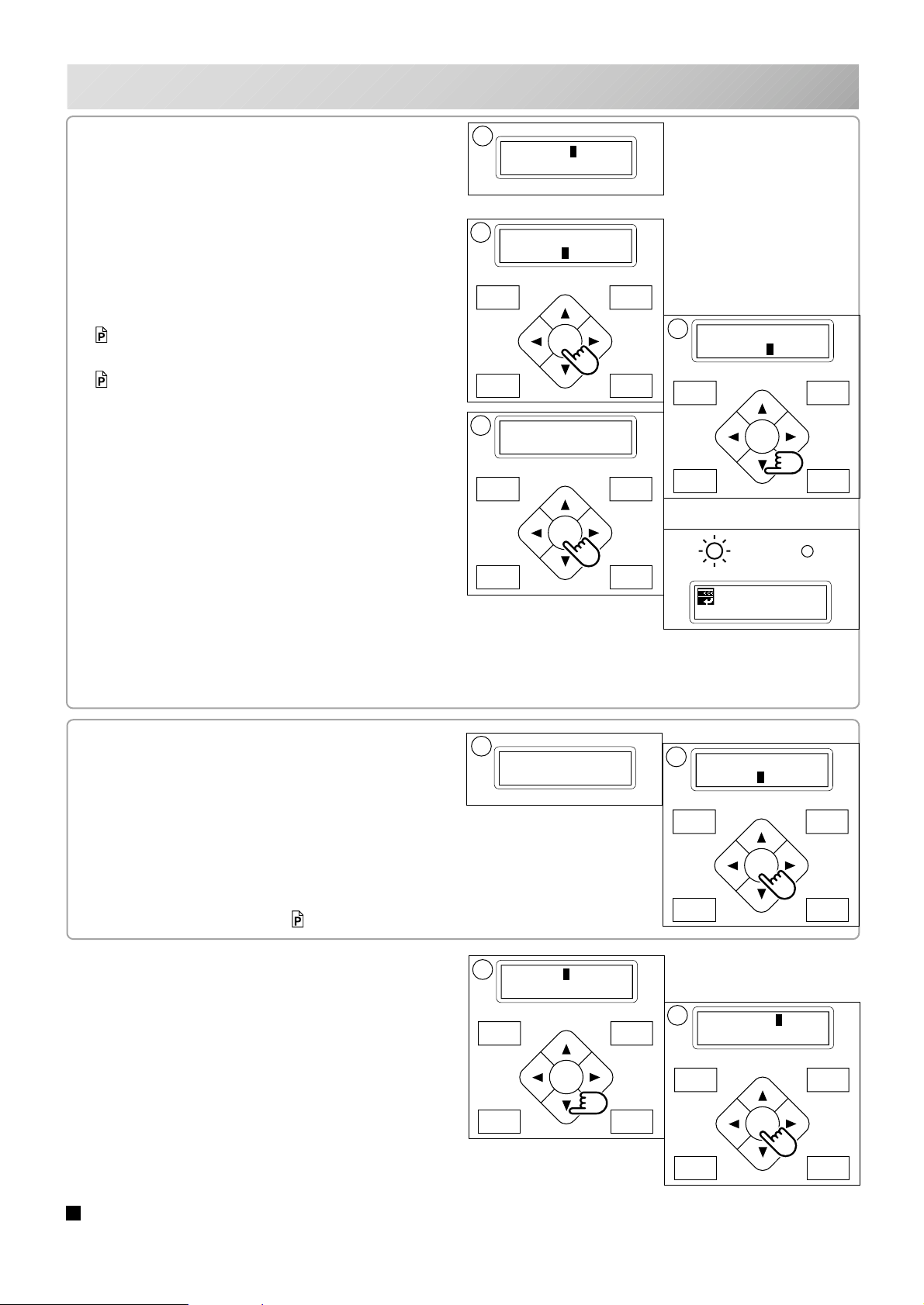
P.FOOT T.CUT
MENU
FORWARD
ENT.
P.FOOT T.CUT
MENU
FORWARD
ENT.
P.FOOT T.CUT
MENU
FORWARD
ENT.
PREPARATION OF PATTERN DATA
5-14
If when you select “On” the following is
displayed.
"Area ovr"... Line length will be too long.
If resetting is needed
B. Press the "ENT." button with the cursor
pointed at "Cancel".
You will be back to #33 above.
Reset the line length again as on page.
5-11 or.
Change the letter size selection as shown.
5-12
If it is acceptable to increase the size as shown
C. Select "OK" by use of the “Down" arrow"
button.
D. Press the "ENT." button.
"NOW LOADING •••" will be appear, new pattern
data will be made and then you will return to
drive mode.
First 8 letters will be shown as the name of the
pattern which you have made by letter selection.
A
Area ovr Cancel
OK
B
[MODE] Refere
On
MENU
ENT.
P.FOOT T.CUT
D
NOW LOADING•••
MENU
ENT.
P.FOOT T.CUT
FORWARD
FORWARD
C
Area ovr Cancel
OK
MENU
ENT.
P.FOOT T.CUT
G
ID:15 Nd: 3
FLOWER
FORWARD
The distance between the letters will be set to
0.8 mm.
If the follo wing is displayed in “Review”
mode.
"Char data not found!"......the letters you have
selected are not available.
F. Press the "ENT." button.
The status will be back to procedure #33.
Set the letter selection.
5-10
Select the review mode “off”
35.Use the “Down” arrow button to point the
cursor to "OFF" at procedure #33.
36.Press the "ENT." button.
The status will be back to procedure #26 as
above.
E
Char data
not found!
35
[MODE] Off
F
[MODE] Refere
On
36
[LETTER] Mode
Please complete the steps from #27 to reconfirm
your selections.
Please reset items from #33 to Review mode
(ON).
All the selected settings will be deleted when the power source is turned off.
Please be careful when making embroidery letters.
-CS -39
5_14 D610
Page 48
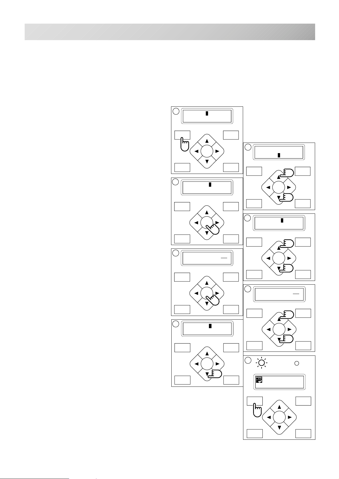
P.FOOT T.CUT
MENU
FORWARD
ENT.
P.FOOT T.CUT
MENU
FORWARD
ENT.
P.FOOT T.CUT
MENU
FORWARD
ENT.
P.FOOT T.CUT
MENU
FORWARD
ENT.
P.FOOT T.CUT
MENU
FORWARD
ENT.
SETTING AUTOMATIC COLOR CHANGE
7
5
Needle numbers are set for each color number
of the selected pattern.
When a color change is set, the machine automatically changes to the selected needle and
continues sewing automatically.
5-15
1. Press the "MENU" button until [MENU] is
showing when the machine is stopped.
2. Press the “Up” or “Down” arrow button until
the cursor points to "Needle.
3. Press the "ENT." button when showing
[NDL].
4. Press the “Up” and ”Down" arrow button to
point the cursor at the required color
change number.
Ex. : Needle no. 4 to be the first color.
5. Press the "ENT." button.
An Underscore will be shown when no needle
has been selected.
1
[MENU] Pattern
Needle
3
[NDL] 1: 0
2: 0
[NDL] 1: 0
2: 0
2
[MENU] Pattern
Needle
4
[NDL] 1: 0
2: 0
MENU
FORWARD
ENT.
P.FOOT T.CUT
6. Press the “Up” and ”Down" arrow" bu tton to
set the preferred needle number.
The number will increase by pressing the “Up”
arrow button.
The number will decrease by pressing the
”Down” arrow button.
7. Press the "ENT." button.
Repeat procedure 4. thorough 7. to set any other
color changes required.
8. Finally, Press the "MENU" button until a
green lamp shows on control box (Drive
Mode).
When the green light shows you are in the Drive
mode and you can start the embroidery.
[NDL] 1: 4
2: 0
6
[NDL] 1: 4
2: 0
MENU
FORWARD
ENT.
P.FOOT T.CUT
8
G
ID: 2 Nd: 4
0
MENU
FORWARD
ENT.
P.FOOT T.CUT
-CS -40
5_15 D610
Page 49
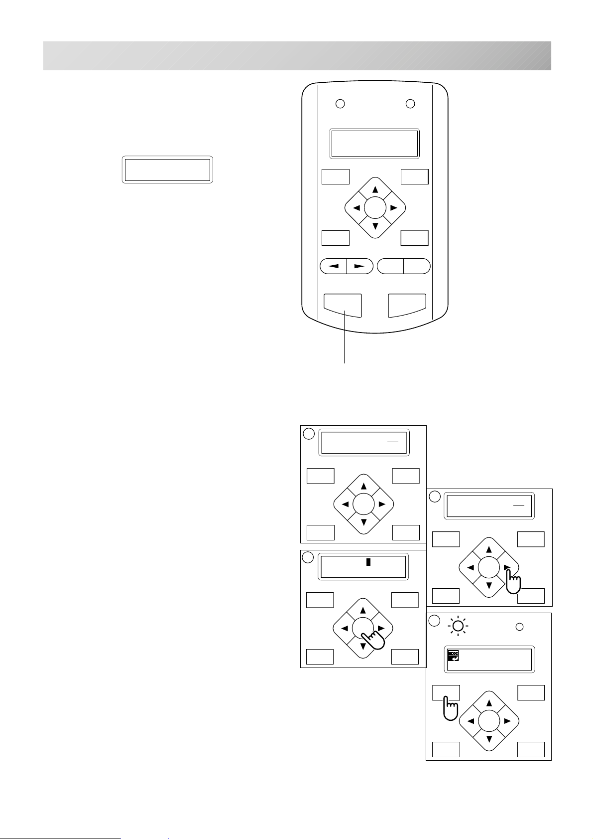
SETTING AUTOMATIC COLOR CHANGE
P.FOOT T.CUT
MENU
FORWARD
ENT.
P.FOOT T.CUT
MENU
FORWARD
ENT.
P.FOOT T.CUT
MENU
FORWARD
ENT.
1
FORWARD
MENU
P.FOOT
T.CUT
ENT.
START STOP
+
-
To set a color change stop
When a color change stop is set to a color
number, the machine will stop after it finishes
sewing the marked needle number.
The following message will be shown.
>>Change Stop
When you wish to start again, press the start
button.
5-16
1. Follow the steps in order from 1. thorough 5
above.
2. After selecting the needle #, press the
”Right" arrow button.
A " * " mark will be shown on the side of the color
number.
If you press the “Left” arrow button, it will
remove the setting.
3. Press the "ENT. button".
You can repeat these steps for each color you
want to stop after.
4. Finally, Press the "MENU" button until a
green lamp shows on control box (Drive
Mode).
Start button
[NDL] 1: 4
2: 4
3
[NDL] 1: 4*
2: 4
2
[NDL] 1: 4*
2: 4
4
G
ID: 2 Nd: 4
0
When a green lamp is showing you are in the
Drive mode and you can start the embroidery.
MENU
ENT.
P.FOOT T.CUT
5_16 D610
FORWARD
-CS -41
Page 50
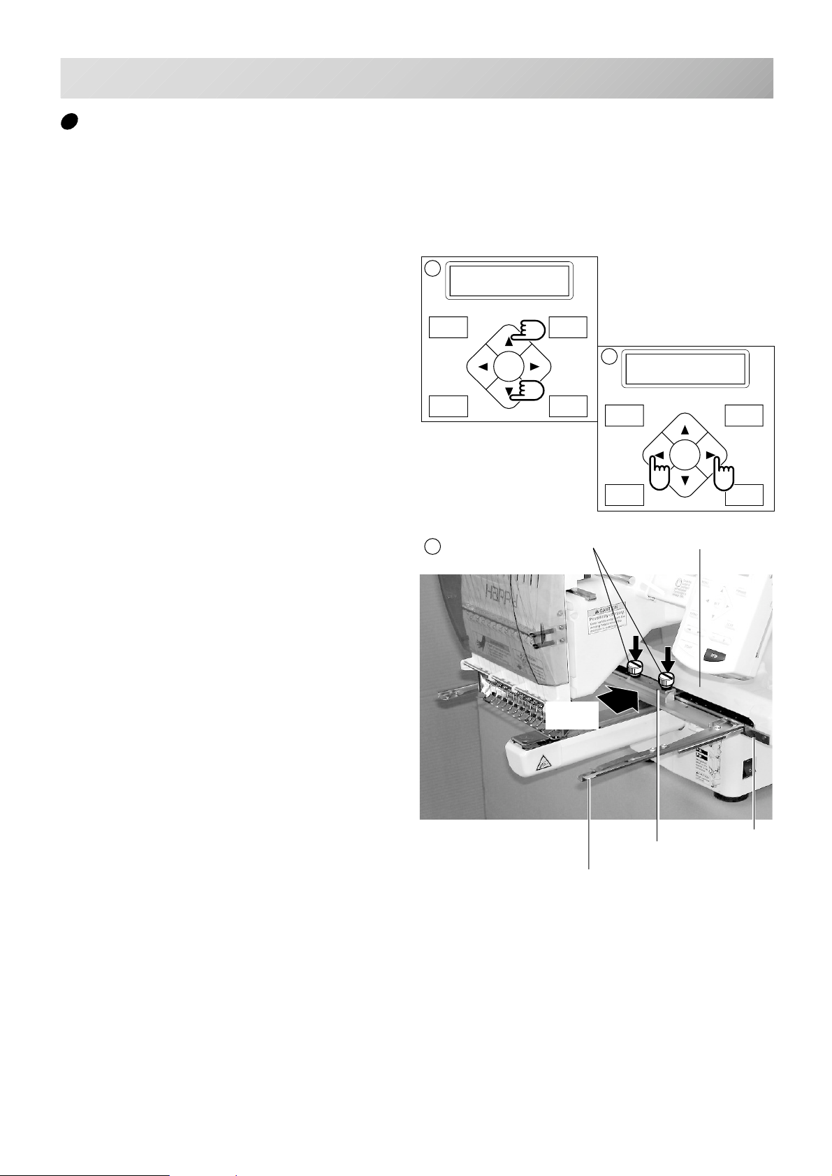
SEWING WITH TUBULAR FRAMES
Installing and removing the frame base
Please attach the frame base to the carriage
when you wish to use a tubular embroidering
hoop.
Please remove it in the reverse order of installation.
6-1
1. Move the carriage to the position as shown
by pressing the “Up” or “Down” arrow buttons on the control box.
2. Move the arm base to the approximate
center of carriage (left to right) using the
“Left” and “Right” arrow buttons.
3. Place the frame base on the carriage guide
and tighten the knob bolt on the tubular arm
holder completely.
Move the frame base right or left when it is hard
go to the knob bolt.
1
X:-234.5
Y: 123.8
MENU
ENT.
P.FOOT T.CUT
3
FORWARD
Knob bolt
2
X: 4.5
Y: 123.8
MENU
FORWARD
ENT.
P.FOOT T.CUT
Carriage
Pushing
against
Fixing base
Guide
Frame base
-CS -42
6_1 G424
Page 51
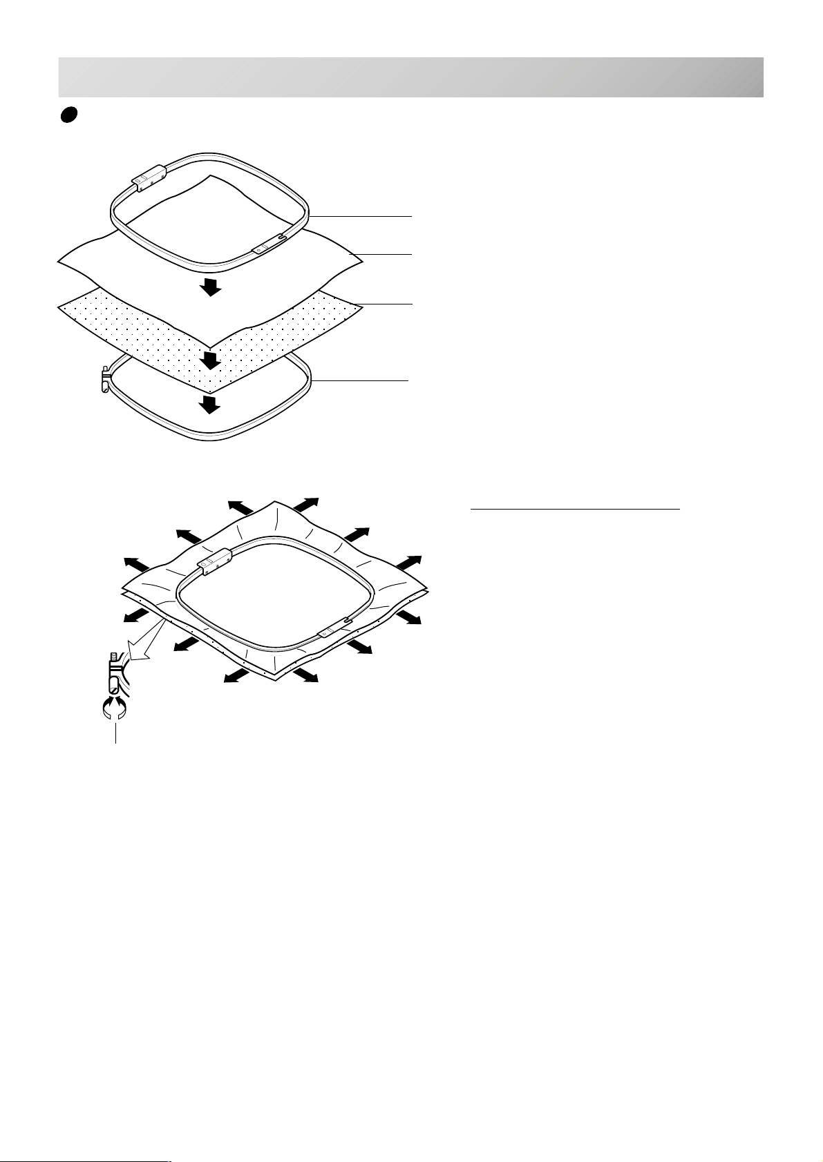
SEWING WITH TUBULAR FRAMES
How to hoop
Inner frame
Cloth
Backing
Outer frame
6-2
Tighten
Please smooth the embroidery cloth before tightening.
Loosen
Please smooth the embroidery cloth in all directions, but do not stretch it.
i
-CS -48
6_2 D610
Page 52
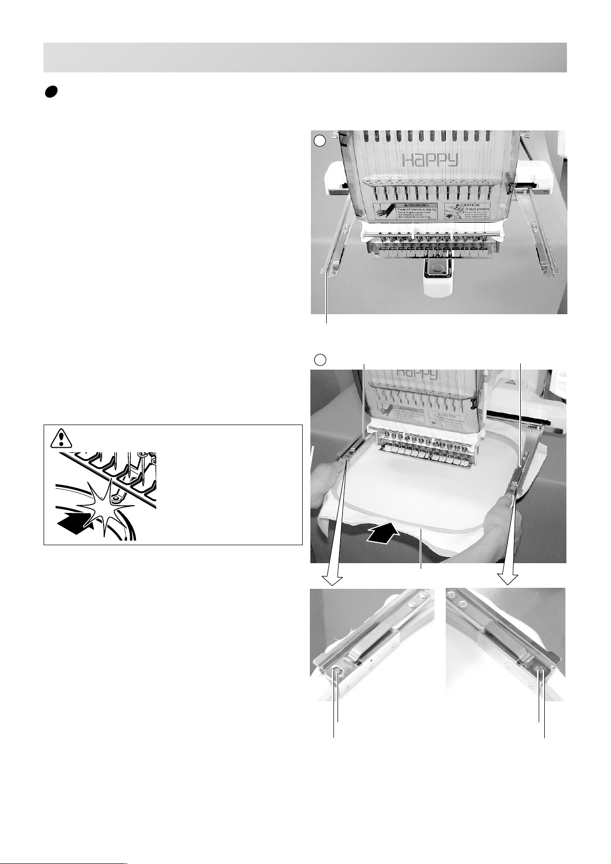
SEWING WITH TUBULAR FRAMES
1
Putting the hoop on the machine
1. Move the frame base to the approximate
center position before inserting the tubular
embroidering frame.
Frame base
6-3
2. Insert the embroidery frame.
Make sure that the holder pins are inserted into
the positioning holes of the frame base on each
side.
CAUTION: To avoid problems.
Please do not hit or
push embroidering hoop
to presser foot.
2
Holder
Embroidering hoop
Holder
Positioning pin
Positioning hole
Positioning pin
Positioning hole
-CS -46
6_3 H402
Page 53
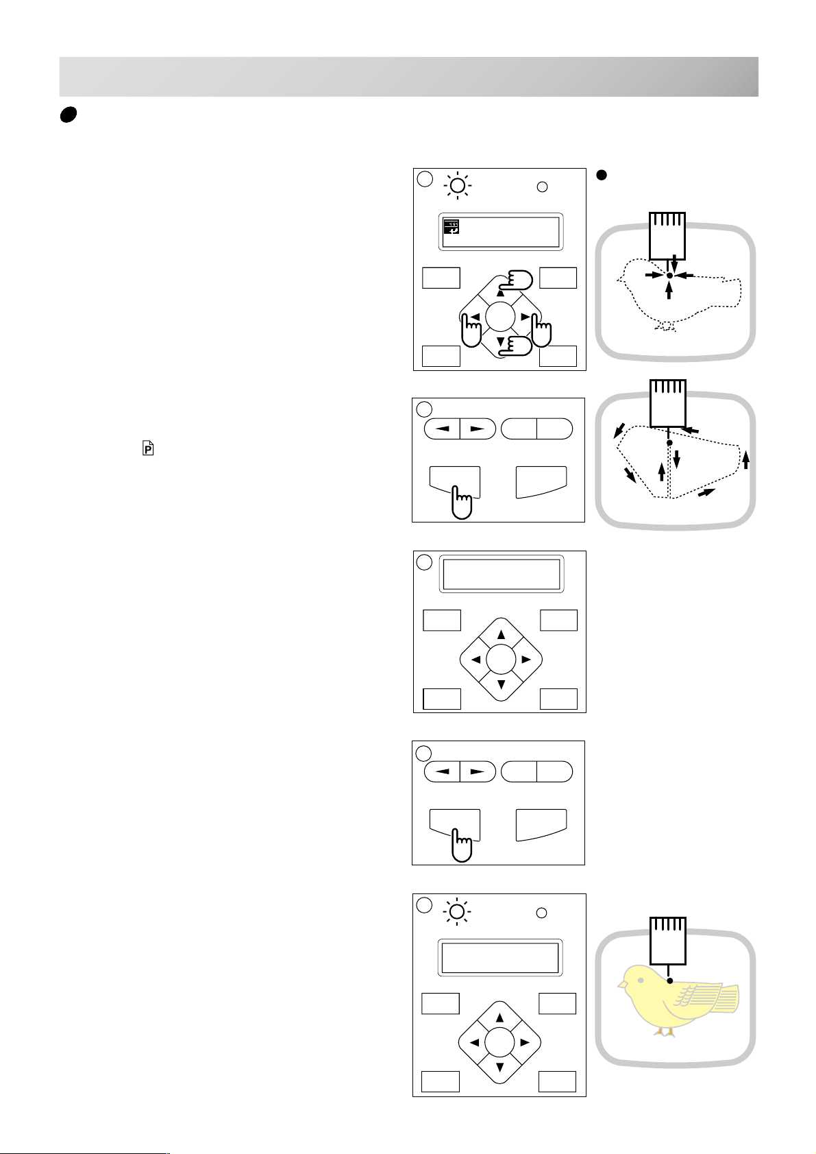
SEWING WITH TUBULAR FRAMES
FORWARD
P.FOOT T.CUT
MENU
ENT.
FORWARD
P.FOOT T.CUT
MENU
ENT.
1
FORWARD
P.FOOT T.CUT
MENU
ENT.
Starting to sew
6-4
1. Press the arrow buttons (up, down, left,
right) and move embroidering frame position to the origin point of the pattern (usually
the center).
2. Press the "START" button.
The embroidering frame moves for the design
trace. 5-3
Make sure that the pressure foot and needle
does not hit the frame.
If you push and hold the start button, the machine will discontinue the trace and move to the
first stitch point.
3. The display will show ">>Trace end" and
the embroidery frame will stop moving.
G
ID: 2 Nd: 4
0
2
START STOP
3
>>Trace end
: Original point
(Start point)
-
+
You can confirm outline
trace and the position of the
design.
The embroidering frame has moved to the first
stitch point of the pattern.
4. If you are satisfied that the design will fit into
the hoop by viewing the trace, Press the
"START" button again to begin sewing.
5. After finishing your design, the display will
show ">>End" and the machine will stop.
The embroidery frame returns to the origin point
automatically.
.
4
START STOP
5
G
>>End
-
+
-CS -45
6_4 D610
Page 54
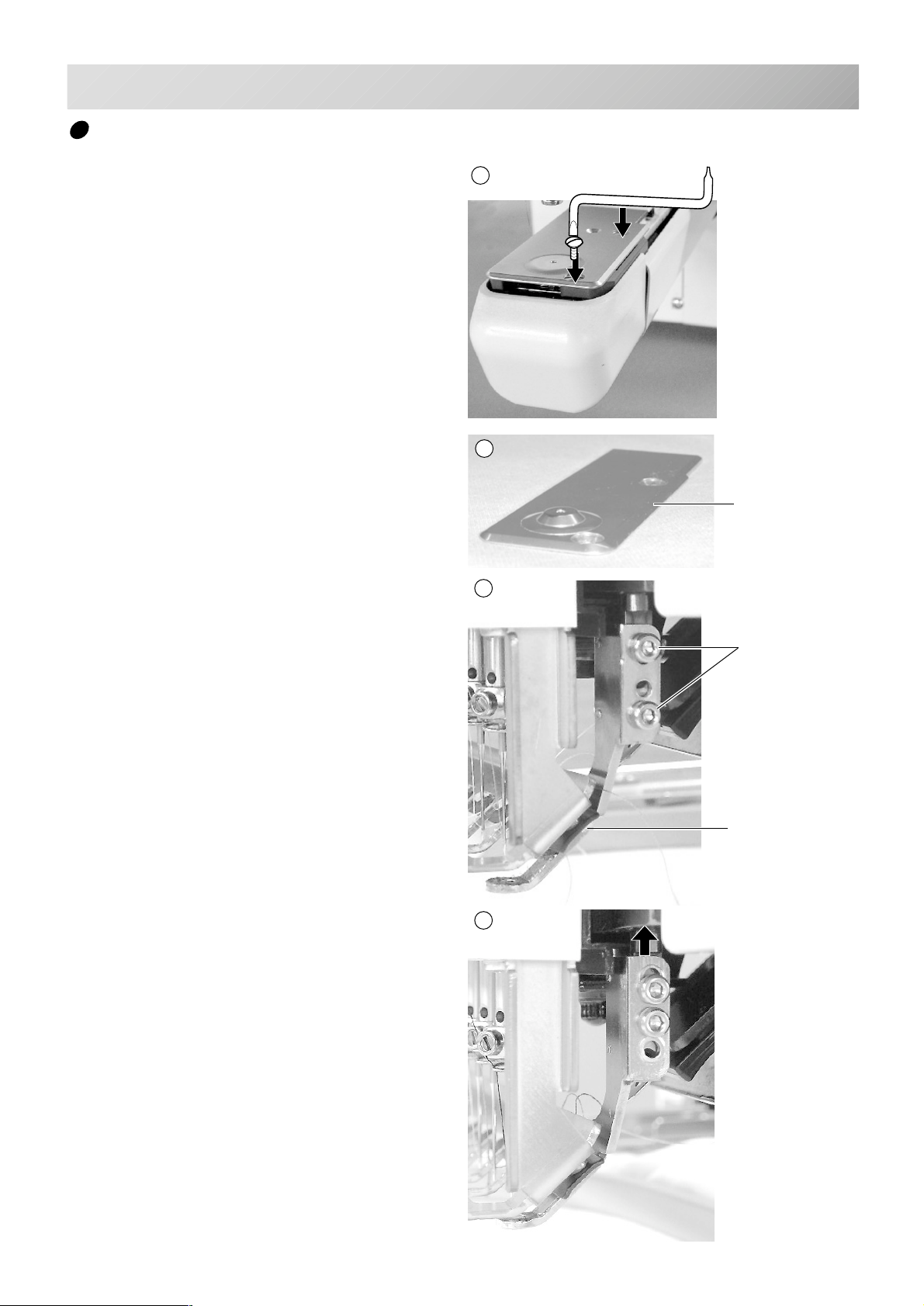
CAP FRAME (OPTION)
3
4
Changing the needle plate
You need to change the needle plate when you
embroider a cap.
1. Remove the set screw (2 pieces) by offset
driver and remove the needle plate.
7-2
1
2. Put the needle plate for cap on the bed and
tighten with the set screw.
3. Loosen the set screw (upper side) of pressure foot and unscrew the set screw (lower
side).
2
Needle plate for
cap frame
Set screw
Pressure foot
4. Press up the pressure foot and tighten set
screw (upper side) and tighten set screw
(lower side) as it shown in the diagram.
-CS -47
7_2 E801
Page 55
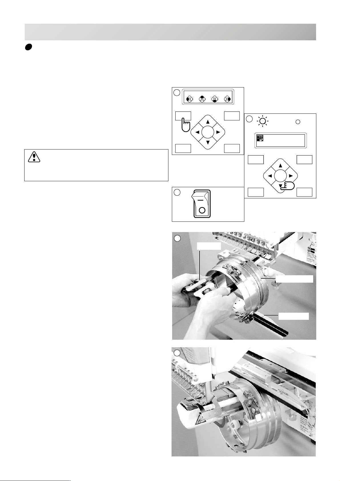
3
5
CAP FRAME (OPTION)
Installing and removing the cap drive frame
You need to install the cap drive frame into the
carriage when you embroider a cap.
Please remove by reverse order of these step.
7-3
1. If you press and hold the menu button for a
few second, you will see the direct frame
movement menu when the machine is
stopped.
2. Press the “Down” arrow button.
Embroidery frame moves to the center automatically.
CAUTION: To prevent accidents.
The frame moves quickly.
Keep hands away from the frame.
3. Turn off the power switch.
4. Hold the arc guide by hand and the rail
bracket has to be faced downward, then
install into the bed as showing picture.
1
Org Top Cnt Pos
MENU
FORWARD
ENT.
P.FOOT T.CUT
ON
OFF
4
Arc guide
2
G
ID: 2 Nd: 4
BIRD
MENU
FORWARD
ENT.
P.FOOT T.CUT
When you hold the cap drive frame assembly, be
sure to hold it by the guide.
If you hold the rail bracket, your fingers will be
pout between the rail bracket and the rail bracket
rotary cylinder and rail bracket can get out of
place.
5. Move the cap drive frame backwards away
from you and rotate the rotary cylinder until
the rail bracket is upward as shown at right.
Rotary cylinder
Rail bracket
-CS -48
7_3 G424
Page 56
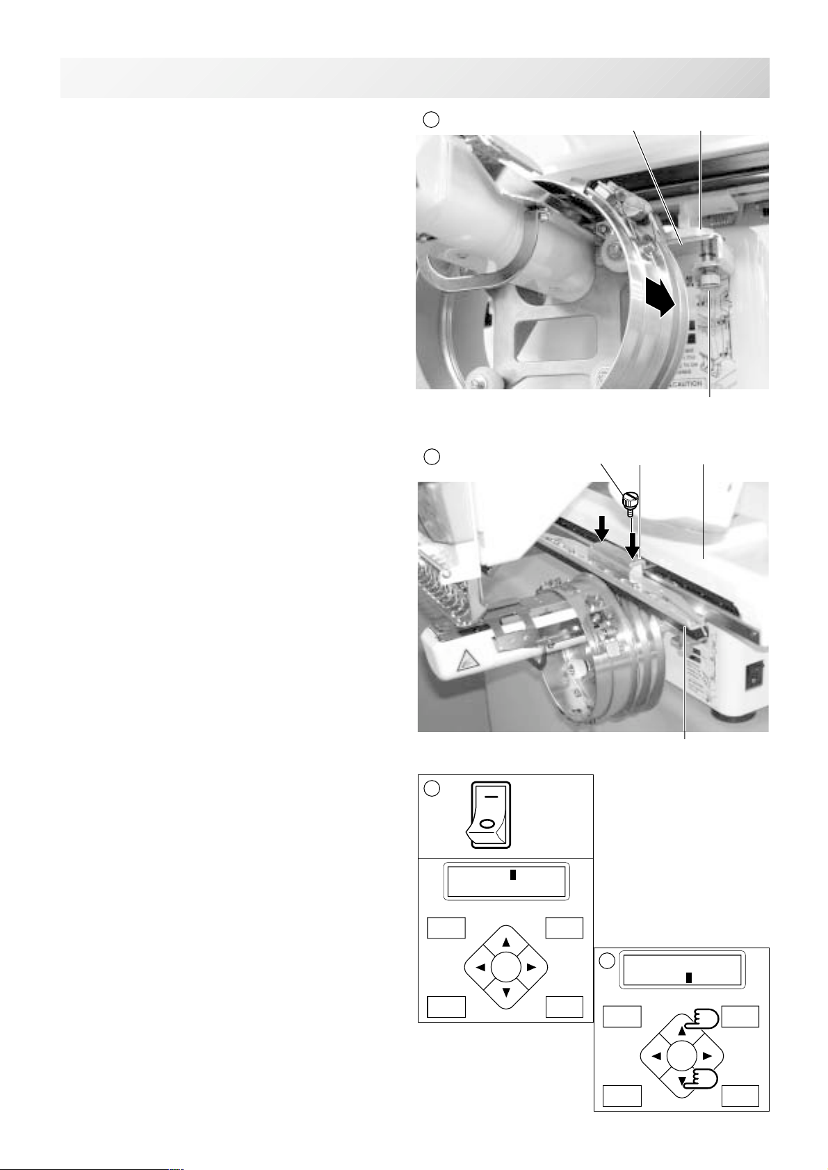
CAP FRAME (OPTION)
6
FORWARD
P.FOOT T.CUT
MENU
ENT.
7-4
6. Move the cap drive frame in the direction of
the arrow, adjust right-and-left mount base
to carriage arm and fix them by knob bolts.
7. Fix the rail bracket to fixing base by knob
bolts.
You can move the fixing base right or left when it
is hard to get to the set screw.
Mount base
7
Knob bolt
Fixing base
Carriage arm
Knob bolt
Carriage
8. Turn on the power switch.
9. Press the “Up” or “Down” arrow button,
moves the cursor to the selected cap frame.
S.Cap : Standard cap frame
W.Cap : Wide cap frame
S.OPF : One-point frame (small)
L.OPF : One-point frame (large)
8
[Frame] S.Cap
W.Cap
MENU
ON
OFF
FORWARD
ENT.
P.FOOT T.CUT
Rail bracket
9
[Frame] S.Cap
W.Cap
7_4 K101
-CS -56
Page 57
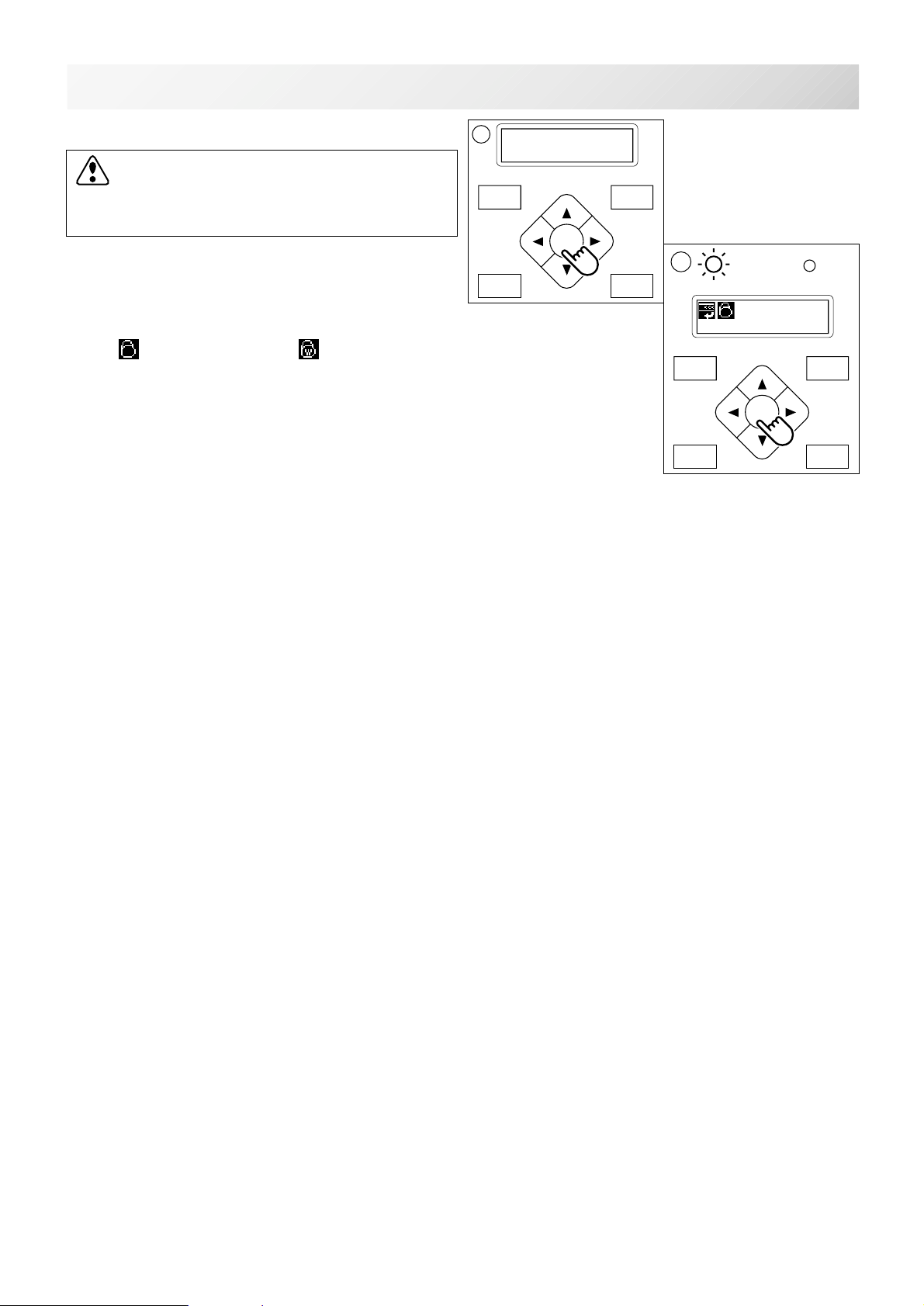
CAP FRAME (OPTION)
10
FORWARD
P.FOOT T.CUT
MENU
ENT.
7-4b
10.Press the "ENT. button".
CAUTION: To prevent accidents.
The frame moves quickly.
Keep hands away from the frame.
11.Press the "ENT. button".
The cap drive frame moves to the center of
embroidery area automatically.
(Normal cap frame) or (Wide cap frame)
will be indicated on the panel.
Then Cap Mode will be set.
Caution !!
Frame Moves
11
G
ID:10 Nd: 4
BIRD
MENU
FORWARD
ENT.
P.FOOT T.CUT
-CS -57
7_4b K101
Page 58
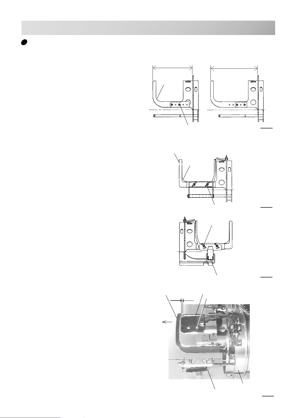
CAP FRAME (OPTION)
Normal cap frame
7-5
Adjustment
When you hoop a cap on the cap frame, please
adjust in the following manner:
1. Adjust position of clamp support to the
height of the cap. (Fig. 1)
Adjust the height by removing the inner
screws at left and right.
If you adjust position of clamp support and
shorten distance H, embroidery area will be
reduced in Y direction (depth).
2. Adjust the clamp to fit the clamp support.
(Fig. 2)
Loosen wing nuts at left and right to adjust.
H (Max.)
Clamp
support
Clamp
Screw
Clamp
support
Wing nut
H (Min.)
Fig. 1
Fig. 2
3. Adjust up and down position of the hook
according to the thickness of the cap to
adjust clamp tension. At this moment, the
hook should open and close without feeling
too tight.
(For adjustment, proceed to procedure 5
below).
Use the wing nuts for adjustment. (Fig. 3)
If the hook is extremely tight, it will damage the
cap frame permanently.
4. Put the cap frame without a cap to cap drive
on the machine.
(Please refer to operation 8 "Hooping caps"
on next page for mounting).
At this time, adjust so that guide on cap
drive frame doesn't strike clamp support
and gap is reduced as small as possible.
Remove screws at left and right to adjust.
(Fig. 4)
Clamp
support
Toward you
Wing nut
Guide
Gap Screw
Hook
Fig. 3
Cramp (Open)
Cap drive
Fig. 4
-CS -50
4_5 E201
Page 59
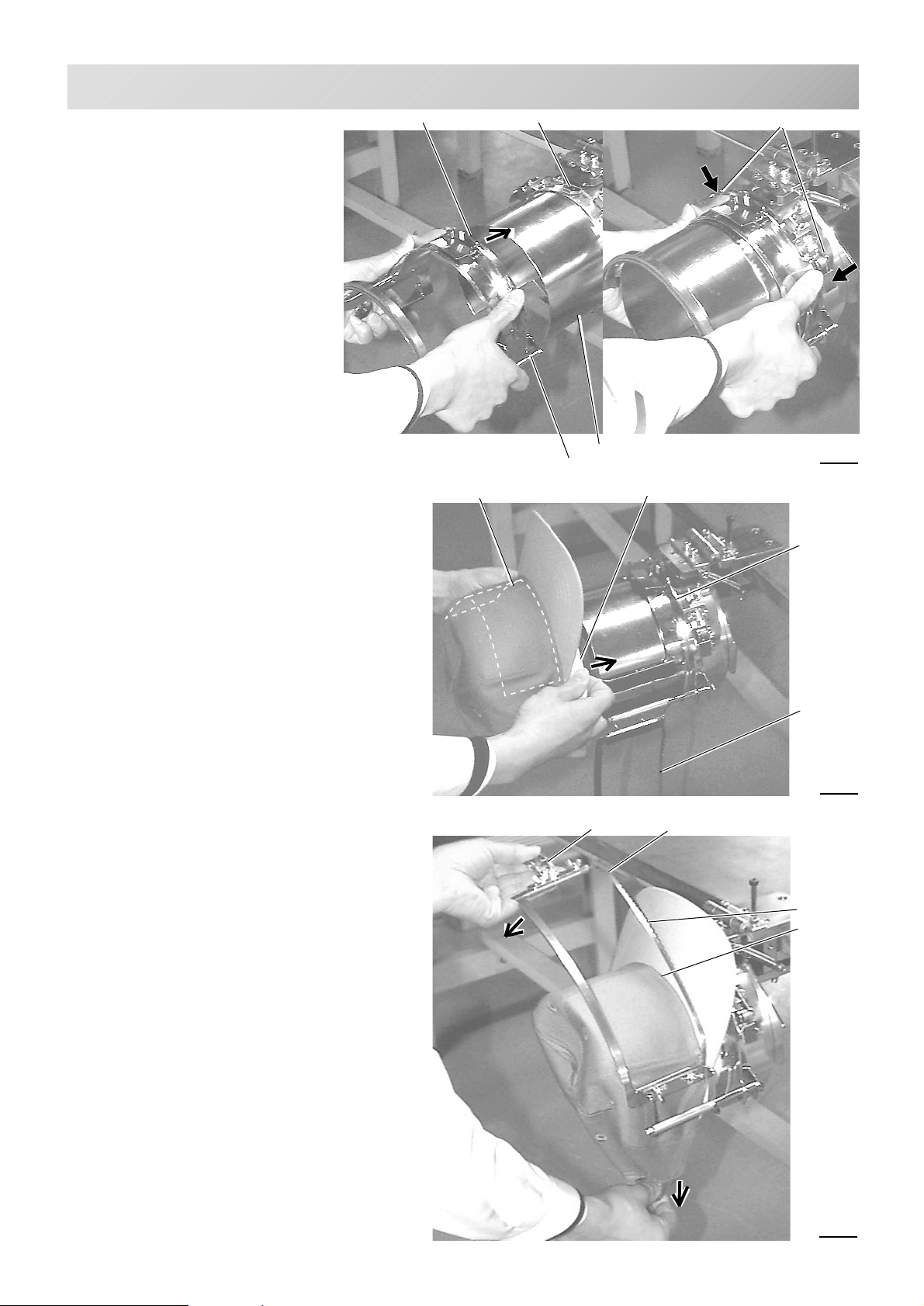
CAP FRAME (OPTION)
Hooping caps
1. Place cap stretcher securely
on a sturdy work bench.
2. As shown in Fig. 5, hold cap
frame with both hands and
place on cap stretcher. By
pushing locking levers at 2
places with fingers, place cap
frame so that center guide of
cap stretcher fits in concave
area of cap frame.
7-6
Center guideConcave
Locking levers
Confirm that the cap frame is securely
placed on cap stretcher.
3. As shown in Fig. 6, open clamp and
keep open to the right.
4. Turn the sweatband of the cap inside
out a slide onto the cap frame as
shown.
Place it so that the edge of the sweatband contacts the flange of the cap
frame.
Please place one or two sheets of nonwoven fabric (backing) of standard thickness under unstructured caps.
5. As shown in Fig. 7, pull back part of cap
and hook it on the hook and smooth out
creases on cap.
At this time, align the center of the cap
to the center mark on the cap frame so
that notched portion of the clamp fits
into the seam of the visor.
Nonwoven fabric
Cap stretcher
Cap frame
Hook
Fig. 5
liner
Flange
Clamp
Fig. 6
Clamp
Notched
portion
Seam
6. Latch the hook, taking care not to
cause wrinkles in the cap.
If you can't get rid of wrinkles on the cap,
adjust the cap frame again according to
"Adjustment" on the previous.
Fig. 7
-CS -51
7_6 E201
Page 60
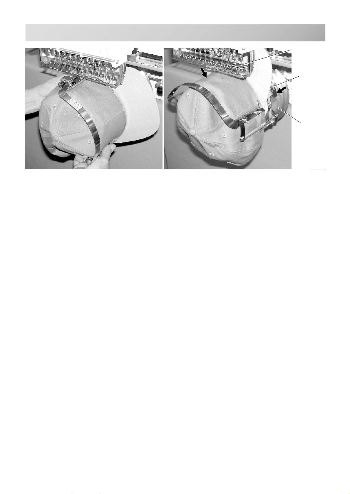
CAP FRAME (OPTION)
7. Remove the cap frame from the cap
stretcher.
7-7
Center guide
Hold lever
Cap drive
frame
Fig. 8
8. As shown in Fig. 8, place the cap frame on
cap the drive frame.
You will have to rotate the brim of the hat to
the side in order to get past the needle
case.
Then, push the holder lever in the 2 places
shown, and place the cap frame on so that
the center guide of the drive frame assembly
fits into the cap frame notch.
Confirm that the frame is firmly seated on the cap
drive frame assembly without any gaps.
If there is a gap between the cap frame or the
cap drive holding lever doesn't go into the hole of
the cap frame, loosen the set screw on the hold
lever for adjustment.
-CS -52
7_7 FA27
Page 61
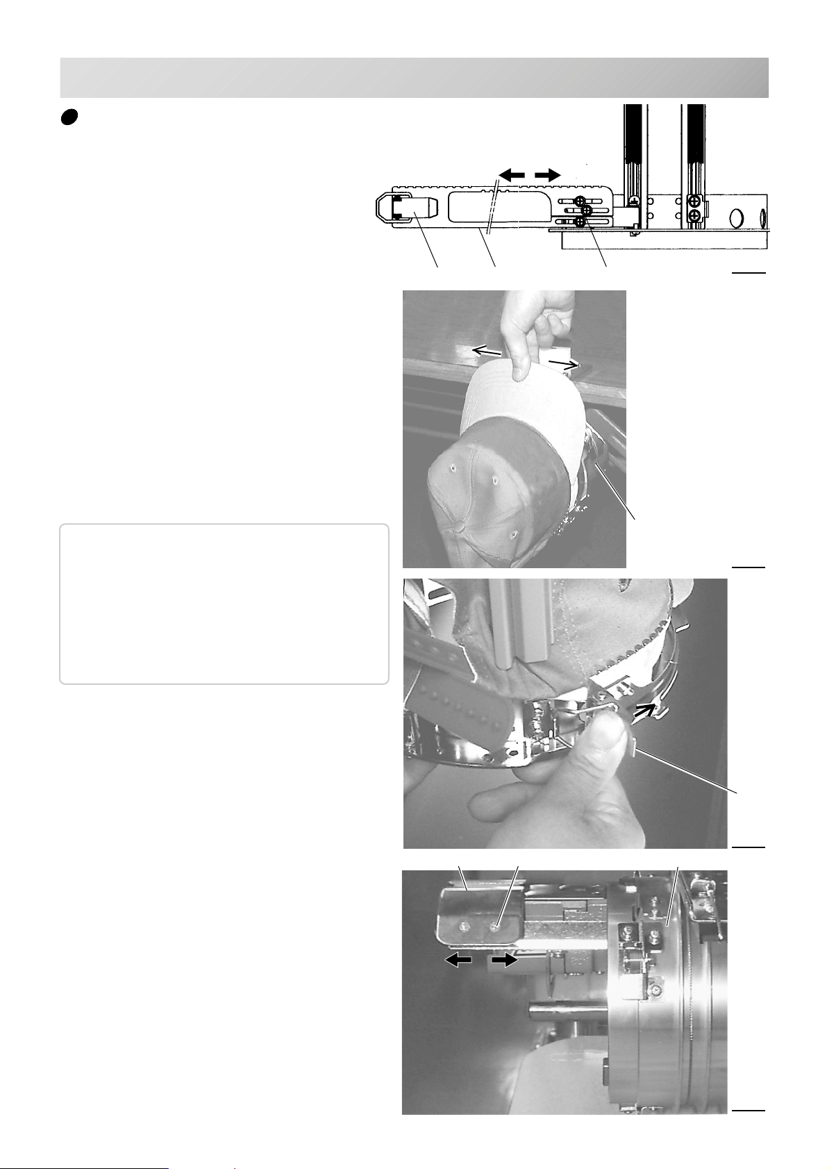
CAP FRAME (OPTION)
Wide cap frame
Adjustment
When you fix cap to cap hold frame, please
adjust in the following manner.
Make sure to do the adjustment of the cap
hold frame. If it is not adjusted properly, it
may cause the deformity, damage of the
cap, damage of the cap hold frame and
break of the cap grip.
After adjusting the cap hold frame, make
sure the cap to be set properly.
1. Adjust the length of the cap grip to suit
the thickness of the fabric. At this moment, hook should open and close
without feeling heavy.
(For the adjustment follow the next page
"Hooping caps" item 1 to 5.)
The adjustment to be done by three
adjusting screws. (Fig. 1)
If the cap grip is loose, even after
hooked the cap is not fixed tightly and
the cap is moving. (Fig. 2)
(Thick fabric)
Hook
Loosen
Tighten
(Thin fabric)
Adjusting screwCap grip
Cap stretcher
7-8
Fig. 1
Fig. 2
If the cap grip is too tight, you feel
heavy when it is hooked and the grip
bites into the cap too much. (Fig. 3)
If you feel hook extremely heavy in opening
and closing, there is a case that cap hold
frame will lose its shape or damage.
2. Adjust the guide position to suit the
height of the cap.
Remove screws at left and right to
adjust. (Fig. 4)
Guide
High Low
Screw
Hook
Fig. 3
Cap drive frame
Fig. 4
-CS -53
7_8 E201
Page 62
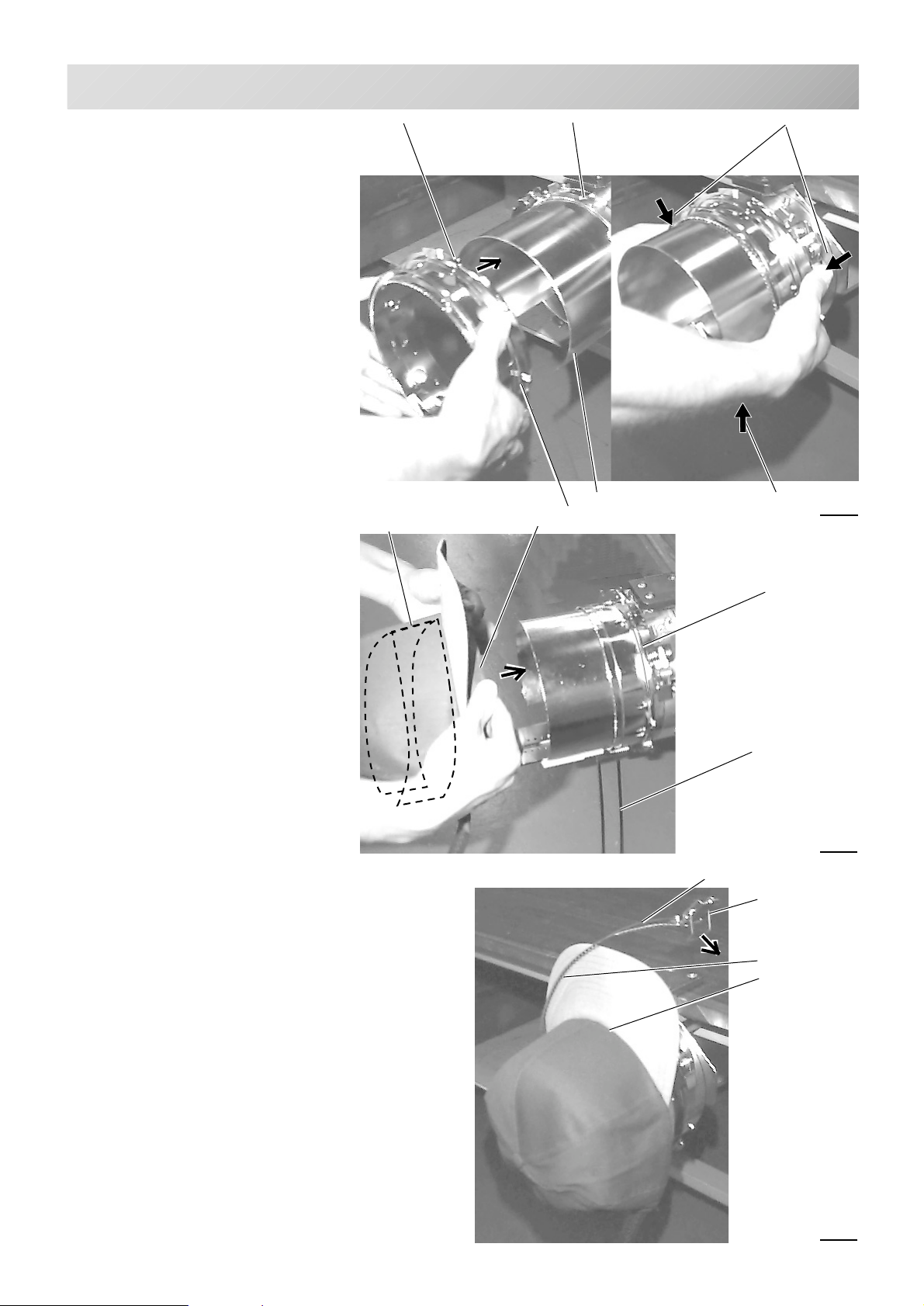
CAP FRAME (OPTION)
7-9
Hooping caps
1. Place cap stretcher securely on
sturdy work bench.
2. As shown in Fig. 1, hold cap
hold frame with both hands and
place on cap stretcher. By
pushing hold lever at 3 places
in arrow marks with fingers,
place cap hold frame so that
center guide of cap stretcher
gets in concave of upper cap
hold frame.
Confirm that cap holder frame is
securely placed on cap stretcher
without gap.
3. As shown in Fig. 2, remove cap
grip and keep open to the left.
Concave
Nonwoven fabric
Center guide
liner
Cap strecher
Cap hold frame
Hold lever
Hold lever
Fig. 1
4. Extend fore half of liner inside
cap toward outward and place
on cap stretcher.
At this moment, place it so that
tip of liner contacts flange of
cap hold frame.
Please place one or two sheets of
nonwoven fabric (backing) of standard thickness under unstructured
caps.
The length of nonwoven fabric
should be some as one of round of
cap.
5. As shown in Fig. 3, place hook
so as to have visor of cap get in
gap between cap grips.
At this moment, set center of
cap to center mark on cap hold
frame so that notched portion
of clamp gets into seam of
visor.
Close hook.
Flange
Cap grip
Fig. 2
Cap grip
Hook
Notched portion
Seam
Fig. 3
-CS -54
7_9 E201
Page 63
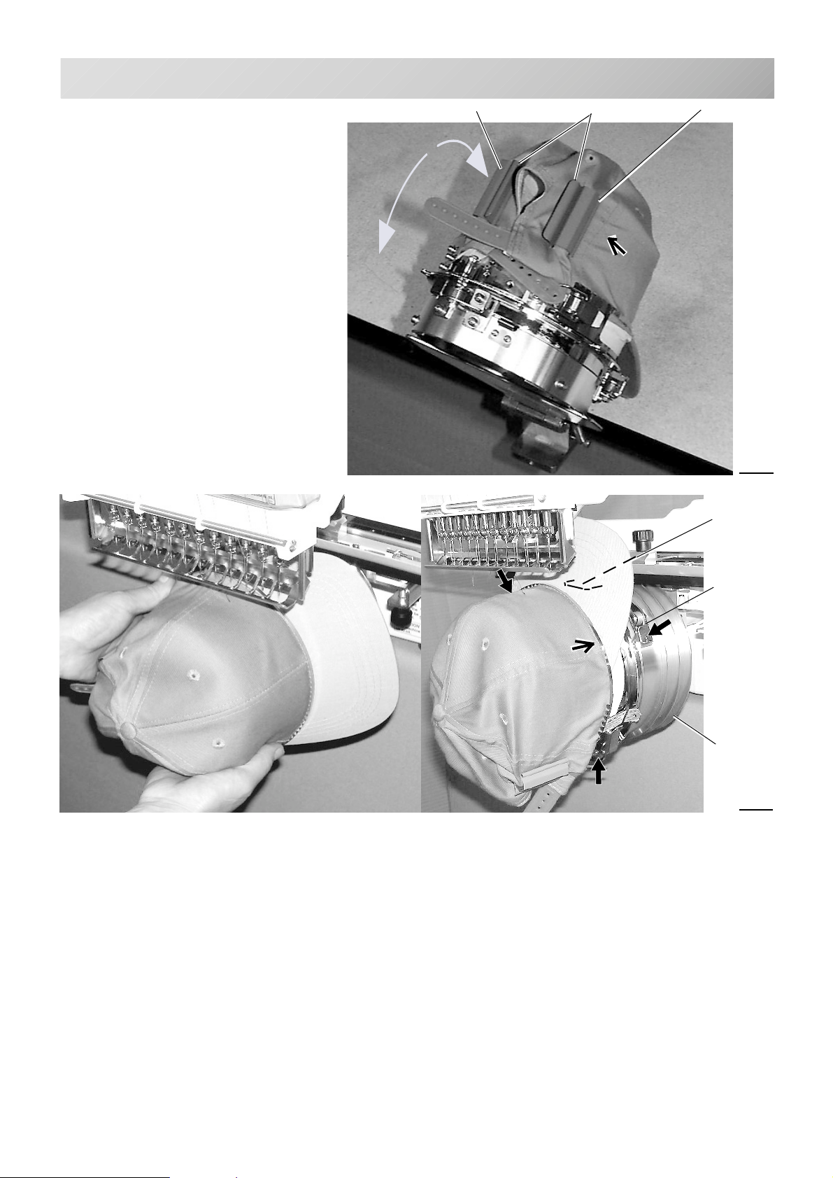
CAP FRAME (OPTION)
7-A
6. As shown in Fig. 4, tip the cap
stretcher forward.
Clip the back of the cap in two
places by stretching the crease out
as shown by the arrows.
Make the clip lever face the inside.
Clip
ClipLever for clip
Fig. 1
7. Remove the cap holder frame from the cap
stretcher.
8. As shown in Fig. 5, place the cap holder frame
the cap drive frame assembly.
Push the hold lever in at 3 places as shown by
the marks and place the cap holder frame so
that center guide of the drive frame assembly
gets in the upper cap holder frame.
Center
guide
Hold lever
Cap drive
frame
assembly
Fig. 2
Confirm that the cap holder frame is firmly attached to
the cap drive frame assembly without any gaps.
If there is a gap between cap holder frame and the
cap drive frame, or hold lever doesn't go into hole on
the cap holder frame well, loosen the set screw on the
lever to adjust.
-CS -55
7_A FA27
Page 64
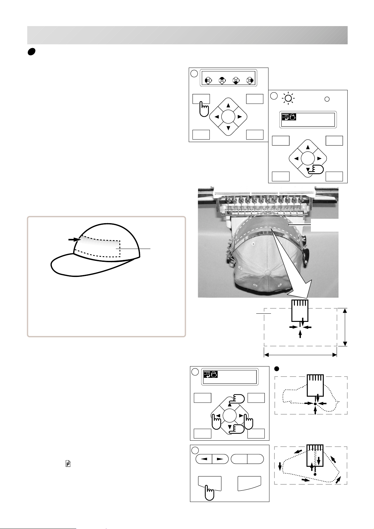
CAP FRAME (OPTION)
FORWARD
P.FOOT T.CUT
MENU
ENT.
FORWARD
P.FOOT T.CUT
MENU
ENT.
P.FOOT T.CUT
MENU
FORWARD
ENT.
START STOP
+
-
Starting to sew
7-B
1. If you press and hold the menu button for a
few second, you will see the direct frame
movement menu if the machine is stopped.
2. Press the “Down” arrow button.
Embroidery frame moves to the center of embroidery area automatically.
Embroidery
area
1
Org Top Cnt Pos
2
G
ID: 2 Nd: 4
BIRD
Embroidery
area
There is a case that the upper part of the cap cannot
be embroidered satisfactory depending on shape of a
cap.
We recommend to change design position or reducing
size of the design.
Refer to the instruction book of "Happy link" to reduce
the size of the design.
*1 Actual embroidery area will be restricted in
accordance with design and shape of a cap.
3. Press the arrow buttons (up, down, left,
right) and move the embroidering frame
position to the origin point of the pattern
(usually the center).
Once the cap drive is installed, the design
automatically rotates upside down for cap sewing.
4. Press the "START" button.
The embroidering frame moves for the design
trace. 5-3
Make sure that the pressure foot or needle does
not hit the frame.
If you push and hold the start button, the machine will discontinue the trace and move to the
first stitch point.
Embroidery area (Max. *1)
3
ID: 2 Nd: 4
0
4
180mm
290mm
(Normal cap frame)
(Wide cap frame)
:Original point (Start point)
You can confirm the outline
and position of design.
-CS -56
7_B E801
67mm
Page 65
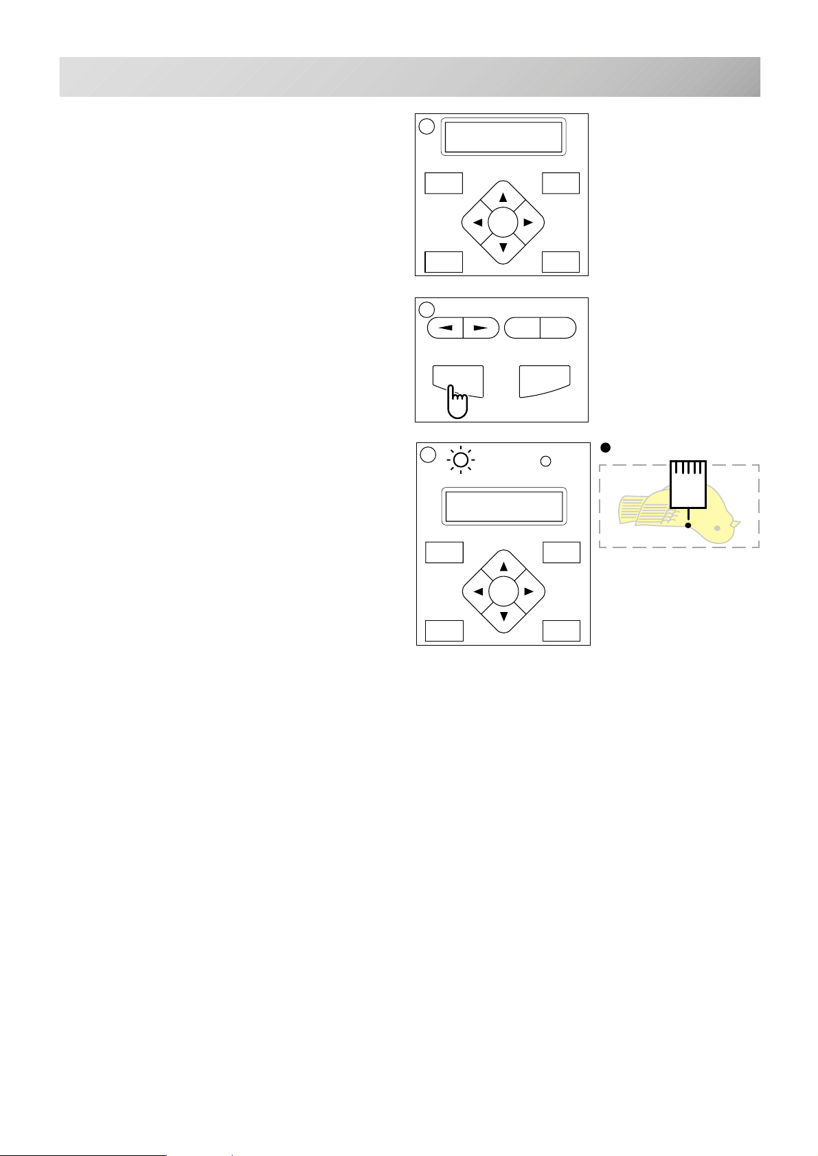
CAP FRAME (OPTION)
FORWARD
P.FOOT T.CUT
MENU
ENT.
FORWARD
P.FOOT T.CUT
MENU
ENT.
7
7-C
5. The display will show ">>Trace end" and
the embroidery frame will stop moving.
The embroidering frame has moved to the first
stitch point of the pattern.
6. If you are satisfied that the design will fit into
the hoop by viewing the trace, Press the
"START" button again to begin sewing.
7. After finishing your design, the display will
show ">>End" and the machine will stop.
The embroidery frame returns to the origin point
automatically.
5
>>Trace end
6
START STOP
G
>>End
-
+
:Original point (Start point)
-CS -57
7_C E201
Page 66
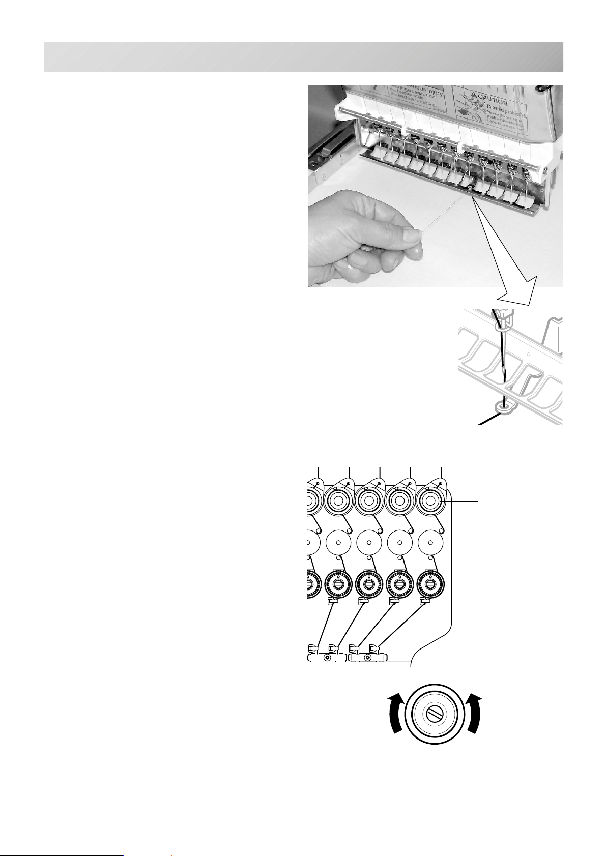
ADJUSTING THE THREAD TENSIONS
1. With the thread going through the hole of
the pressure foot, pull it out slowly toward
the front.
8-1
2. Adjust the Minor thread tension by the first
tension knob and then the second Thread
tension knob.
According to the type of upper thread and cloth.
Pressure foot
First tension
Second tension
LoosenTighten
-CS -58
8_1 E801
Page 67
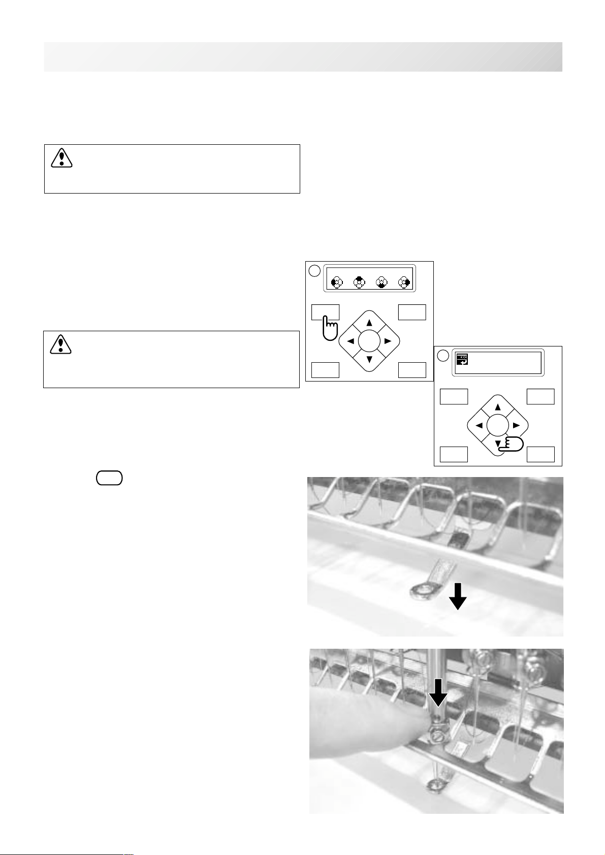
ADJUSTING THE LASER POINTER (OPTION)
P.FOOT T.CUT
MENU
FORWARD
ENT.
P.FOOT T.CUT
MENU
FORWARD
ENT.
8-2
Laser pointer indicates the needle position.
The beam of laser is coming from right upper side, thus the position of laser pointer can be
changed depending on the height of surface of fabric.
Please adjust then angle of laser pointer depending on thickness of fabric and type of frame
CAUTION: Laser beam (Class 1)
Do not stare into the beam.
1. Set fabric on the frame, then put white
paper to the position of needle and fix by
Scotch tape.
2. If you press and hold the menu button for a
few second, you will see the direct frame
movement menu when the machine is
stopped.
CAUTION: To prevent accidents.
The frame moves quickly.
Keep hands away from the frame.
3. Press the “Down” arrow button.
The embroidery frame will move to the center .
4. Press
P.FOOT
for down the Pressure foot.
2
Org Top Cnt Pos
3
ID: 2 Nd: 4
BIRD
5. Please down needle for make needle point
mark to white paper.
-CS -64
8_2 I604
Page 68
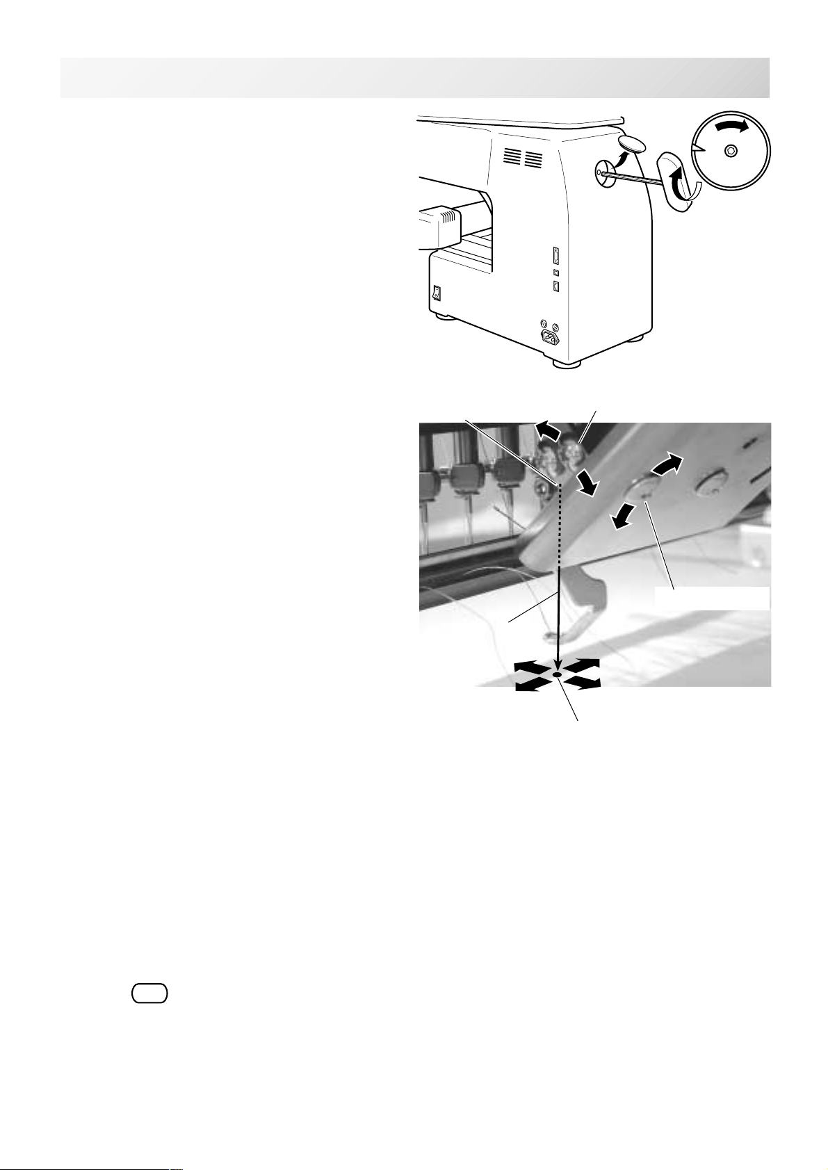
ADJUSTING THE LASER POINTER (OPTION)
6. Remove the cap over the small hole in the
rear of the machine. Using a 3 mm hexagonal wrench, Please turn the main shaft and
adjust it to the “C” point.
Down the needle and making needle point mark.
8-3
C
7. Little loose the "Fixing screw for X" and
move the screw head up and down for
adjust red laser mark point to needle point
mark.
8. Little loose the "Fixing screw for Y" and
move the screw head up and down for
adjust red laser mark point to needle point
mark.
9. Fix the fixing screw for X and the fixing
screw for Y.
Source of laser
Laser beam
X direction
Fixing screw for Y
Fixing screw for X
Y direction
Hole on paper
10.Check the hole position on paper and the
point of laser beam, and take paper out.
11.Press
P.FOOT
for up the Pressure foot.
-CS -65
8_3 I604
Page 69
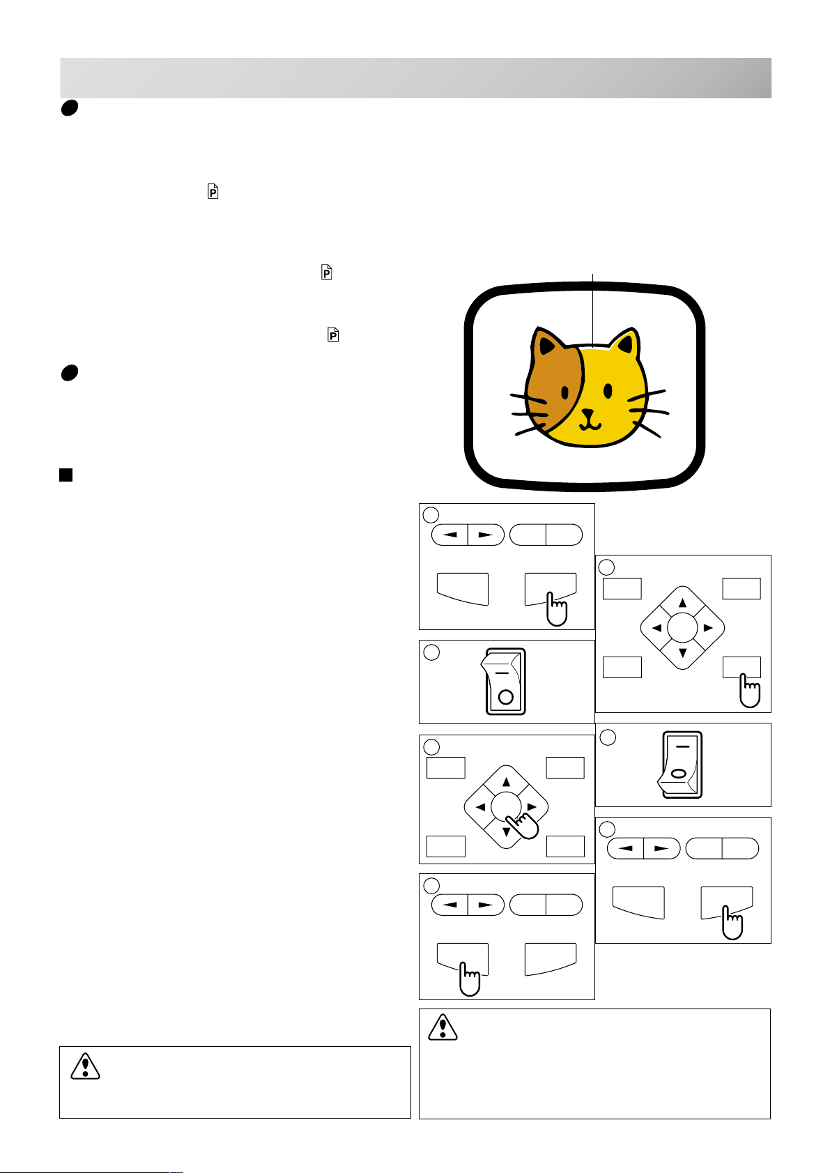
SEWING
P.FOOT T.CUT
MENU
FORWARD
ENT.
9-1
What to do if the thread breaks while sewing
In case thread breaks and thread shorts while sewing. The machine senses a thread break and
the frame moves back several stitches from the broken point and the machine stops.
(This function is to prevent open sections in the design when you start sewing again. See
Thread break back.
5-2)
If the upper thread breaks
Thread upper thread again.
(Reference to thread upper thread
4-6)
In case bobbin thread breaks
Thread lower thread again.
(See preparation of bobbin winding.
4-5)
Stopping and resuming sewing
If you wish to turn off the machine power while
sewing, you may re-start sewing from the
suspended point after turning on the machine
power again and then re-starting.
You need carefulness that suspending ma-
chine with sewing of pattern data half done
left and when some time pass and re-start
sewing, cloth crease may occurs, there
might be gap between sewing part which
you add after stopping machine and re-start
sewing and it's cloth crease by sewing.
To suspend sewing
1. Stop the sewing by pressing the "STOP"
button.
As an example; An unsatisfactory gap between
blocks and block. Because stopped machine at half
point of embroidery and shrunk material.
1
-
+
2
START STOP
3
ON
MENU
P.FOOT T.CUT
FORWARD
ENT.
2. Press the "Thread trim" button.
3. Turn off the power switch.
5
To start embroider again from half point of design
4. Turn on the power switch.
5. Press the "ENT." button.
The carriage and frame will move to the front
side and the right automatically and then will
return to the original point.
7
6. Back up several stitches from the stopped
point by pressing the stop button 3-4 times.
7. Start sewing again by pressing the "START"
button.
When turning power on, the embroidery
CAUTION: To prevent accidents.
When performing a thread trim, be careful of
the needle which will enter the fabric.
frame will make a sudden move to the front
and right side. Please keep your hands and
body from contacting the machine.
OFF
4
6
-
+
START STOP
START STOP
CAUTION: To prevent accidents.
9_1 D610
ON
OFF
-
+
-CS -59
Page 70
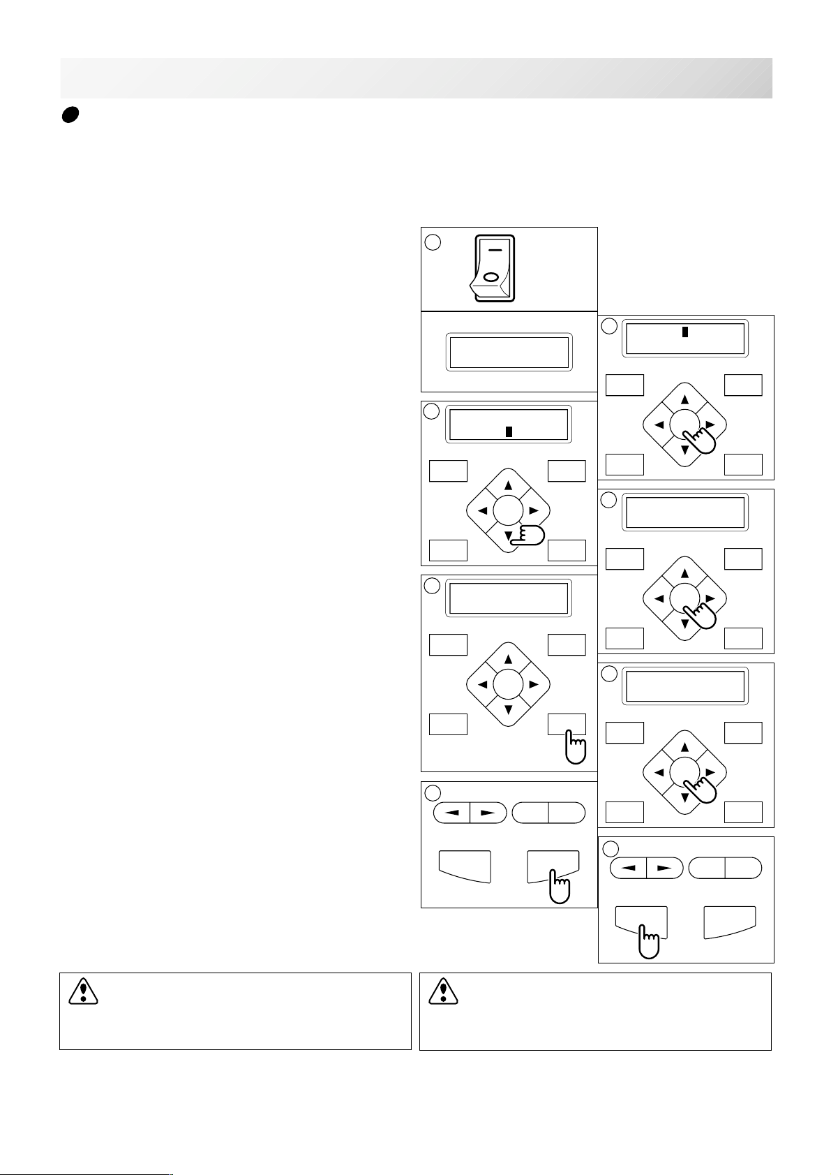
START STOP
+
-
SEWING
P.FOOT T.CUT
MENU
FORWARD
ENT.
P.FOOT T.CUT
MENU
FORWARD
ENT.
1
7
9-2
Loss of power while embroidering
If you had a power failure while embroidering, follow these instructions and you can restore the
position of the frame and pattern data its state before the power failure.
1. Turn on the power switch.
2. Press the "ENT." button.
3. Press the “Down” arrow button until the
cursor points to "Auto" (Automatic restore).
4. Press the "ENT." button.
The main shaft will make one rotation and stop at
the "C" point (proper stop position).
5. Press the "Thread trim” button.
The needle will go down and trim the thread.
error E-050
C point
3
[ERR] Manual
Auto
5
Caution !!
Frame moves
ON
OFF
2
[ERR] Manual
Auto
MENU
ENT.
P.FOOT T.CUT
4
Caution !! main
shaft turns
MENU
ENT.
P.FOOT T.CUT
FORWARD
FORWARD
6. Press the "ENT." button.
The carriage and frame move to the front and
right side automatically and then return to the
original point.
7. Back up several stitches from the stopped
point by pressing the stop button 3-4 times.
8. Start sewing again by pressing the "START"
button.
CAUTION: To prevent accidents.
When performing a thread trim, be careful of
the needle which will enter the fabric.
6
Caution !!
Frame moves
MENU
ENT.
P.FOOT T.CUT
8
-
START STOP
CAUTION: To prevent accidents.
The frame moves quickly.
Keep your hands away from the frame.
FORWARD
+
9_2 D610
-CS -70
Page 71
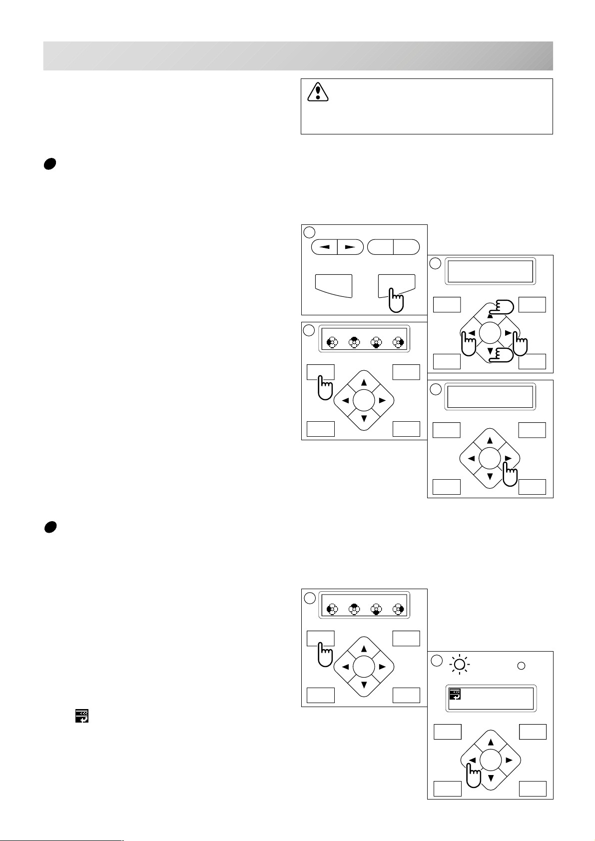
SEWING
START STOP
+
-
1
9-3
CAUTION: To prevent accidents.
The frame moves quickly.
Keep hands away from the frame.
Moving the hoop while embroidering then returning to the correct location (Position)
If you wish to move the embroidery frame at a midpoint of the design, follow these steps.
1. Stop the sewing by pressing the "STOP"
button.
2. Press an “Arrow ” button (up, down, left,
right) to move the embroidery hoop.
3. If you press the “MENU” for few second,
you will see the direct frame movement
menu.
4. Press the “Right” arrow button.
The frame will automatically return to the correct
position before it was moved.
And you return to drive mode.
1
3
Org Top Cnt Pos
MENU
ENT.
P.FOOT T.CUT
FORWARD
2
X:-234.5
Y: 123.8
MENU
ENT.
P.FOOT T.CUT
4
ID:10 Nd: 4
1230
MENU
ENT.
P.FOOT T.CUT
FORWARD
FORWARD
Moving to the beginning position (Origin)
The frame returns to the origin point (beginning position of design).
1. If you press and hold the “MENU” button for
a few seconds, you will see the direct frame
movement menu when the machine is
stopped.
2. Press the “Left” arrow button.
The frame will move to the origin point and the
data will be at the same point.
(Top) will be indicated on the panel.
You will then return to the drive mode.
If you want to get back to the previous status
from the origin point, do #1 and #2 above again.
Org Top Cnt Pos
MENU
ENT.
P.FOOT T.CUT
FORWARD
2
G
ID: 2 Nd: 4
BIRD
MENU
ENT.
P.FOOT T.CUT
9_3 D610
FORWARD
-CS -61
Page 72
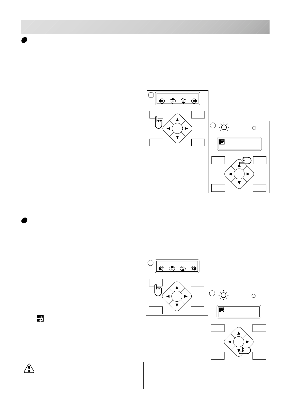
FORWARD
P.FOOT T.CUT
MENU
ENT.
SEWING
1
P.FOOT T.CUT
MENU
FORWARD
ENT.
9-4
Going back to the start of design data (Top)
To stop sewing at a midpoint, change the design location in the hoop, then restart from the
beginning.
If you use the menu item “Top”, you can make the pattern data only return to the start point with
the frame position left where it is.
1. If you press and hold the “MENU” button for
a few seconds, you will see the direct frame
Org Top Cnt Pos
movement menu.
FORWARD
2
G
ID: 2 Nd: 4
BIRD
MENU
FORWARD
ENT.
P.FOOT T.CUT
2. Press the “Up” arrow button.
The design data will return to the beginning point
of the pattern data.
The display returns to drive mode, and the drive
lamp is green.
If you want to get back to the previous status
from “Top”. Do procedure #1, and #2 again.
MENU
ENT.
P.FOOT T.CUT
Placing the design in the center of the selected embroidery frame (Center)
Move embroidery frame position to the center automatically.
1. If you press the “MENU” button for a few
seconds, you will see the direct frame
movement menu.
2. Press the “Down” arrow button.
The embroidery frame will move to the center
automatically, and the pattern data will return to
the start point.
(Top) will be indicated on the panel.
The display returns to the drive mode, and the
drive lamp is green.
If you want to get back to the previous status
from “Center”. Do procedure #1 and #2 above
again.
CAUTION: To prevent accidents.
The frame moves quickly.
Keep hands away from the frame.
1
Org Top Cnt Pos
2
G
ID: 2 Nd: 4
BIRD
9_4 D610
-CS -62
Page 73
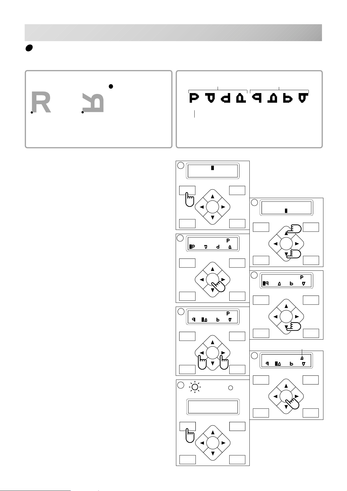
SEWING
P.FOOT T.CUT
MENU
FORWARD
ENT.
P.FOOT T.CUT
MENU
FORWARD
ENT.
P.FOOT T.CUT
MENU
FORWARD
ENT.
P.FOOT T.CUT
MENU
FORWARD
ENT.
G
1
7
Rotating and mirroring designs (Convert)
Convert selected pattern data.
9-5
Setting example
: Start point of pattern
Normal
Mirror reverse + 90°
With start point of pattern as pivot,
the machine changes angle in 90
degree increments through reversed.
1. Press the "MENU" button until [MENU] is
shown when the machine is stopped.
2. Press the “Up” or “Down” arrow button until
the cursor points to "Convert".
3. Press the "ENT." button when showing
[CONVERT].
The control box displays standard pattern adjustment.
Normal
0° 90° 180° 270° 0° 90° 180° 270°
Normal angle
[MENU] Pattern
Needle
Mirror reverse
2
[MENU] Read
Convert
MENU
3
[CONVERT] ( )
P.FOOT T.CUT
FORWARD
ENT.
4. Press the down "Arrow" button.
The control box displays mirror reverse.
5. Press the ”Left” or “Right” arrow button, to
select which you would like.
6. Press the "ENT." button.
The current setting changes to the desired
setting.
7. Finally, Press "MENU" button until the
green lamp on control box is lit.
You can start embroidering.
5
[CONVERT] ( )
ID:10 Nd: 4
1230
MENU
ENT.
FORWARD
4
[CONVERT] ( )
MENU
FORWARD
ENT.
P.FOOT T.CUT
presently setting
6
[CONVERT] ( )
P.FOOT T.CUT
-CS -68
9_5 H701
Page 74
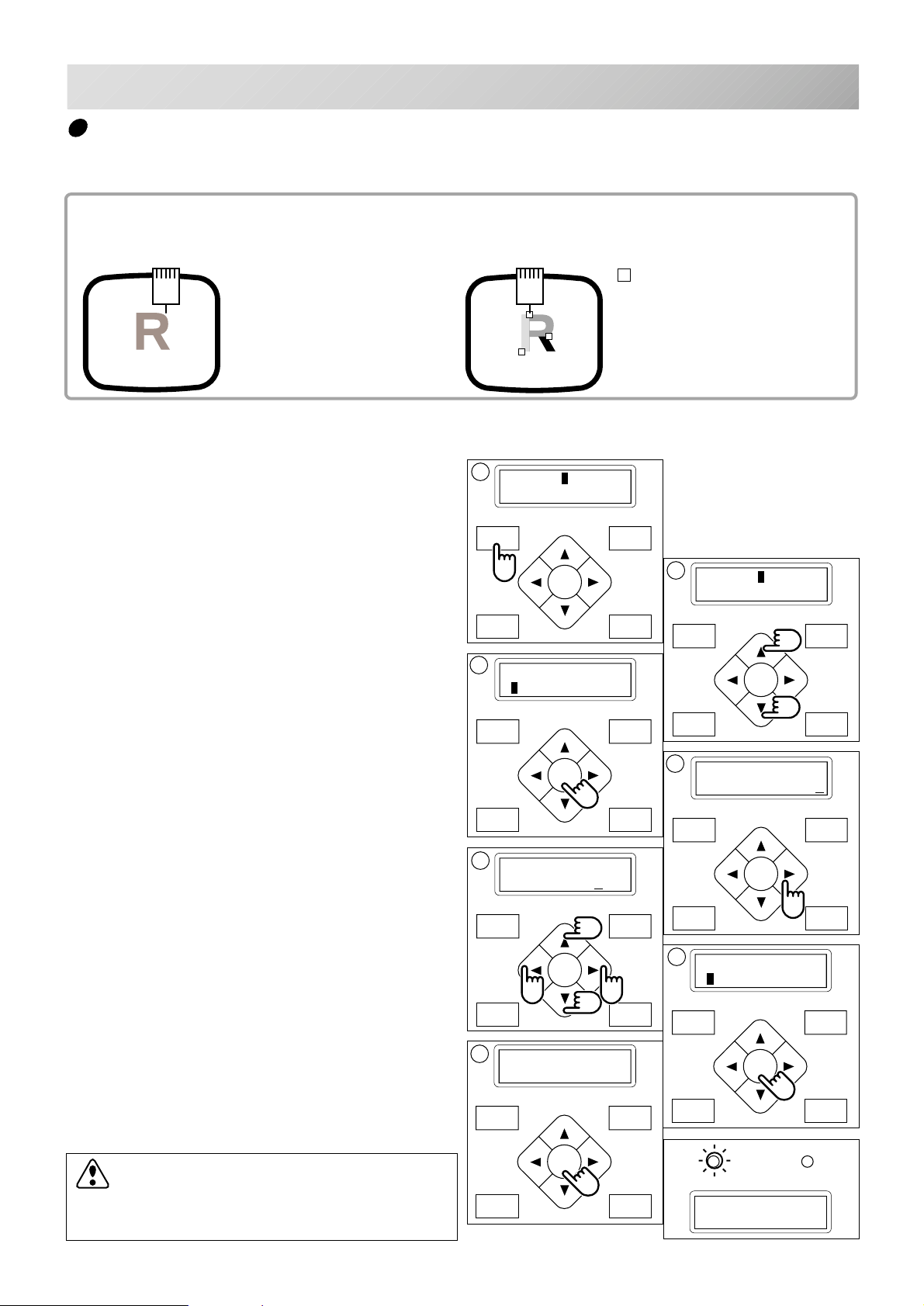
SEWING
P.FOOT T.CUT
MENU
FORWARD
ENT.
3
P.FOOT T.CUT
MENU
FORWARD
ENT.
9-6
Starting from a midpoint of a design (F.Posi)
This function allows you to go directly to a stitch number or a color change and positions the
hoop correctly.
Stitch (Number of stitches )
This moves the frame to any stitch number
desired.
+ : Any stitches
+
Stitch
1. Press the "MENU" button until [MENU] is
shown when the machine is stopped.
2. Press the “Up” or Down” arrow button until
the cursor points to "F •Posi".
3. Press the "ENT." button when showing
[F•POSI].
Change (Color position )
This moves the frame to the beginning of any
color number.
: Beginning of any couloir number
2
3
1
1
[MENU] Pattern
Needle
MENU
ENT.
P.FOOT T.CUT
[F•POSI]
Stitch: 0
FORWARD
2
[MENU] F•Posi
Create
MENU
ENT.
FORWARD
4. Press ”Right” arrow button.
The cursor will move to be under the needle
number.
5. Pressing the ”Left” or ”Right” arrow button,
moves the cursor to select which number to
change.
Press the “Up” or “Down” arrow button to
set each number to the needed stitch number.
The number will increase by pressing the “Up”
arrow button.
The number will decrease by pressing the
”Down” arrow button.
6. Press the "ENT." button.
The cursor will return to the left side.
7. Press the "ENT." button.
After the controller displays "- Calculating -", the
frame will move to the selected stitch number
position.
CAUTION: To prevent accidents.
The frame moves quickly.
Keep your hands away from the frame.
MENU
FORWARD
ENT.
P.FOOT T.CUT
5
[F•POSI]
Stitch: 5643
MENU
FORWARD
ENT.
P.FOOT T.CUT
7
- Calculating -
P.FOOT T.CUT
4
[F•POSI]
Stitch: 0
MENU
FORWARD
ENT.
P.FOOT T.CUT
6
[F•POSI]
Stitch: 5643
G
ID:10 Nd: 4
5643
-CS -64
9_6 D424
Page 75
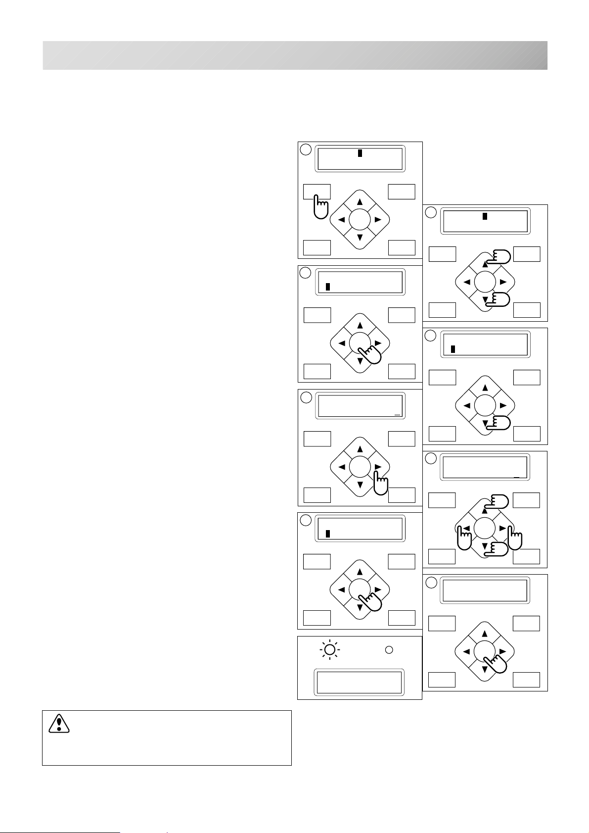
P.FOOT T.CUT
MENU
FORWARD
ENT.
P.FOOT T.CUT
MENU
FORWARD
ENT.
3
P.FOOT T.CUT
MENU
FORWARD
ENT.
P.FOOT T.CUT
MENU
FORWARD
ENT.
SEWING
Change
Starting from a midpoint in the design by color
No.
9-7
1. Press the "MENU" button until [MENU] is
shown when machine is stopped.
2. Press the “Up” or “Down” arrow button until
the cursor points to "F •Posi".
3. Press the "ENT." button when showing
[F •POSI].
4. Press the “Down” arrow button until the
cursor points to "Change".
5. Press the ”Right” arrow button.
The cursor moves to be under the color number.
1
[MENU] Pattern
Needle
[F•POSI]
Stitch: 0
MENU
FORWARD
ENT.
P.FOOT T.CUT
5
[F•POSI]
Change: 1
MENU
FORWARD
2
[MENU] F•Posi
Create
MENU
FORWARD
ENT.
P.FOOT T.CUT
4
[F•POSI]
Change: 0
MENU
FORWARD
ENT.
P.FOOT T.CUT
6. Pressing the “Left” or ”Right” arrow button,
moves the cursor to the selected number.
Press the ”Up” or ”Down” arrow button to
set the number.
The number will increase by pressing the ”Up”
arrow button.
The number will decrease by pressing the
“Down” arrow button.
7. Press the "ENT." button.
The cursor will return to the left side of the
display.
8. Press the "ENT." button.
After the controller displays "- Calculating -", the
frame moves to the selected color position.
CAUTION: To prevent accidents.
The frame moves quickly.
Keep hands away from the frame.
ENT.
P.FOOT T.CUT
7
[F•POSI]
Change: 10
G
ID:10 Nd: 4
5643
6
[F•POSI]
Change: 10
8
- Calculating -
-CS -65
9_7 D610
Page 76
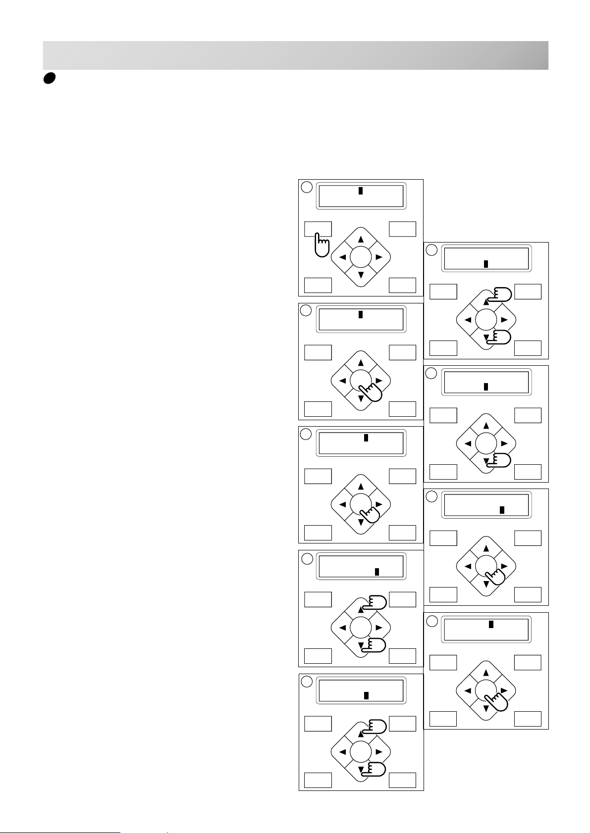
OTHER SETTINGS
FORWARD
P.FOOT T.CUT
MENU
ENT.
FORWARD
P.FOOT T.CUT
MENU
ENT.
FORWARD
P.FOOT T.CUT
MENU
ENT.
7
3
5
FORWARD
P.FOOT T.CUT
MENU
ENT.
FORWARD
P.FOOT T.CUT
MENU
ENT.
Create network
Set this menu when you use Network cable to connect PC and machine(s).
Also use separate network software instruction together with this setup.
9-8
1. Press the "MENU" button until [MENU] is
shown when machine is stopped.
2. Press the “Up” or “Down” arrow button until
the cursor points to "Other".
3. Press the "ENT." button when showing
[OTHER].
4. Press the “Down” arrow button until the
cursor points to "Net".
5. Press the "ENT." button when showing
[NET].
Port No. "Port"
Sets the “Port No.”.
6. Press the "ENT." button.
Now you can change the setting.
1
[MENU] Pattern
Needle
[OTHER] Setup
Clock
[NET] Port
Mac
2
[MENU] Letter
Other
MENU
FORWARD
ENT.
P.FOOT T.CUT
4
[OTHER] Detect
Net
MENU
FORWARD
ENT.
P.FOOT T.CUT
6
[PORT]
Server 7891
7. Press the ”Up” or ”Down” arrow button to
set the number.
The number will increase by pressing the “Up”
arrow button.
The number will decrease by pressing the
”Down” arrow button.
8. Press the "ENT." button.
The setting is fixed.
To cancel your setting, please press the
"MENU" button.
Machine IP "IP"
Sets the “Machine IP Address”.
9. Press the “Up” or “Down” arrow button until
the cursor points to "IP".
[PORT]
Server 7892
9
[NET] Port
IP
MENU
FORWARD
ENT.
P.FOOT T.CUT
8
[NET] Port
IP
MENU
FORWARD
ENT.
P.FOOT T.CUT
-CS -66
9_8 G401
Page 77
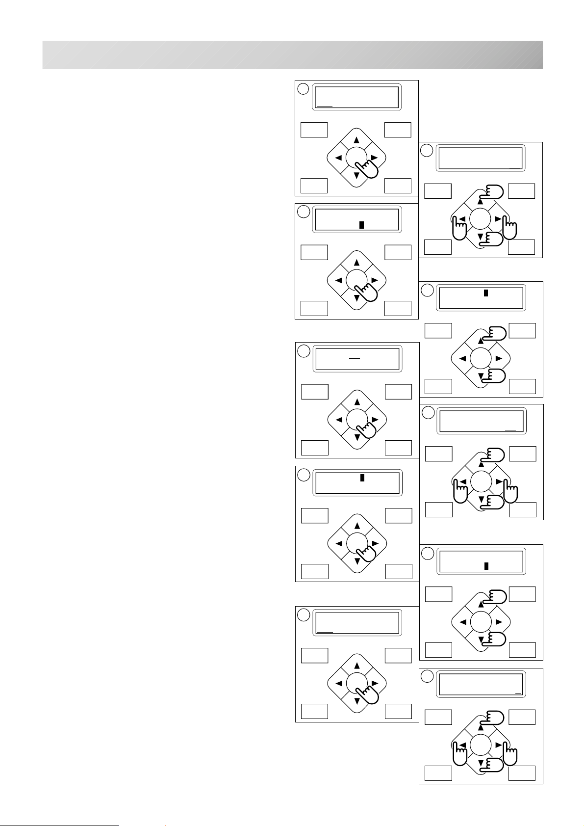
FORWARD
P.FOOT T.CUT
MENU
ENT.
OTHER SETTINGS
FORWARD
P.FOOT T.CUT
MENU
ENT.
P.FOOT T.CUT
MENU
FORWARD
ENT.
P.FOOT T.CUT
MENU
FORWARD
ENT.
FORWARD
P.FOOT T.CUT
MENU
ENT.
9-9
10.Press the "ENT." button.
Now you can change the setting.
11.Move the cursor to the next item you wish to
change by using the “right” and “left” arrow
buttons.
Press the ”Up” or ”Down” arrow button to
set the number.
The number will increase by pressing the “Up”
arrow button.
The number will decrease by pressing the
”Down” arrow button.
12.Press the "ENT." button.
The setting is fixed.
To cancel your setting, please press the
"MENU" button.
Mac Address "Mac"
Sets the "Mac Address".
13.Press the “Up” or “Down” arrow button until
the cursor points to "Mac".
14.Press the "ENT." button.
Now you can change the setting.
15.Move the cursor to the next item you wish to
change by using the “right” and “left” arrow
buttons.
Press the ”Up” or ”Down” arrow button to
set the number.
The number will increase by pressing the “Up”
arrow button.
The number will decrease by pressing the
”Down” arrow button.
16.Press the "ENT." button.
The setting is fixed.
To cancel your setting, please press the
"MENU" button.
10
[IP]
192.168. 1. 10
12
[NET] Port
IP
14
[MAC] 48 50 59
53 48 43
16
[NET] Mac
PC
MENU
FORWARD
ENT.
P.FOOT T.CUT
11
[IP]
192.168. 1. 11
MENU
FORWARD
ENT.
P.FOOT T.CUT
13
[NET] Mac
PC
MENU
FORWARD
ENT.
P.FOOT T.CUT
15
[MAC] 48 50 59
53 48 44
17
[NET] Mac
PC
Server IP Address "PC"
Sets the "Server IP Address".
17.Press the “Up” or “Down” arrow button until
the cursor points to "PC".
18.Press the "ENT." button.
Now you can change the setting.
19.Move the cursor to the next item you wish to
change by using the “right” and “left” arrow
buttons.
Press the ”Up” or ”Down” arrow button to
set the number.
The number will increase by pressing the “Up”
arrow button.
The number will decrease by pressing the
”Down” arrow button.
18
[PC]
192.168. 1. 1
MENU
FORWARD
ENT.
P.FOOT T.CUT
MENU
FORWARD
ENT.
P.FOOT T.CUT
19
[IP]
192.168. 1. 2
-CS -67
9_9 G401
Page 78
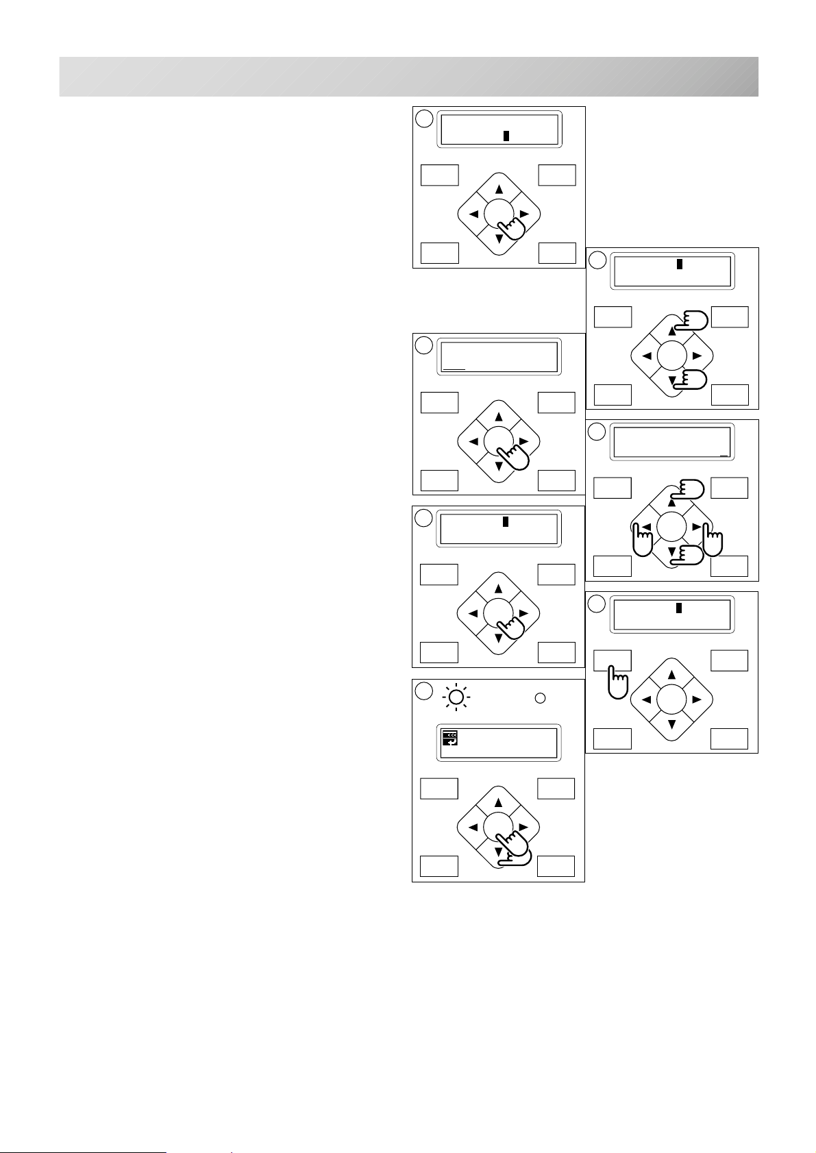
FORWARD
P.FOOT T.CUT
MENU
ENT.
P.FOOT T.CUT
MENU
FORWARD
ENT.
FORWARD
P.FOOT T.CUT
MENU
ENT.
FORWARD
P.FOOT T.CUT
MENU
ENT.
OTHER SETTINGS
9-A
20.Press the "ENT." button.
The setting is fixed.
To cancel your setting, please press the
"MENU" button.
Subnet mask "Mask"
Sets the "Subnet Mask".
21.Press the “Up” or “Down” arrow button until
the cursor points to "Mask".
22.Press the "ENT." button.
Now you can change the setting.
23.Move the cursor to the next item you wish to
change by using the “right” and “left” arrow
buttons.
Press the ”Up” or ”Down” arrow button to set
the number.
The number will increase by pressing the “Up”
arrow button.
The number will decrease by pressing the
”Down” arrow button.
20
[NET] Mac
PC
MENU
FORWARD
ENT.
P.FOOT T.CUT
22
[MASK]
225.225.225. 0
MENU
FORWARD
ENT.
P.FOOT T.CUT
24
[NET] Mask
21
[NET] Mask
MENU
FORWARD
ENT.
P.FOOT T.CUT
23
[MASK]
225.225.225. 1
24.Press the "ENT." button.
The setting is fixed.
To cancel your setting, please press the
"MENU" button.
25.Press the "MENU" button.
26.Press the "Down" button and select "OK"
then press "ENT." button.
(Will change network setting and return to drive
menu.)
Select "Cancel" and press the "ENT." but-
ton.
(Will cancel network setting and back to procedure 24.)
26
G
ID:10 Nd: 4
BIRD
25
[NET] Cancel
OK
-CS -68
9_A G401
Page 79
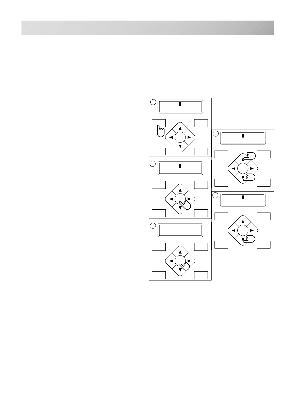
LOG-IN • LOG-OUT • TURN-OFF
FORWARD
P.FOOT T.CUT
MENU
ENT.
FORWARD
P.FOOT T.CUT
MENU
ENT.
FORWARD
P.FOOT T.CUT
MENU
ENT.
FORWARD
P.FOOT T.CUT
MENU
ENT.
FORWARD
P.FOOT T.CUT
MENU
ENT.
5
Log-in is for the use of networking between the machine and PC.
Log-out is for disconnecting the machine from the network between PC.
Turn-off is for the use or turn off the machine when machine is networking.
Refer to the Network software instruction which correspond to this machine.
9-B
1. Press the "MENU" button until the display
shows [MENU] while the machine is
stopped.
2. Press the “Up” or “Down” arrow button until
the cursor points to "Log".
3. Press the "ENT." button when showing
[LOG].
Select "Log-in" when machine Log-out, and
select "Log-out" when machine Log-in automatically.
4. Press “Up” or “Down” key for move cursor
to you wish to select.
Log-in : Log-in
Log-out : Log-out
Pwr off : Power off
1
[MENU] Pattern
Needle
3
[LOG] Log-in
Log-out
2
[MENU] Log
4
[LOG] Pwr off
5. Press the "ENT." button.
Perform you selected "Log-in or Log-out" and
return to drive mode.
If you select "Owr off", machine shut down power
automatically.
-CS -69
9_B G401
Page 80
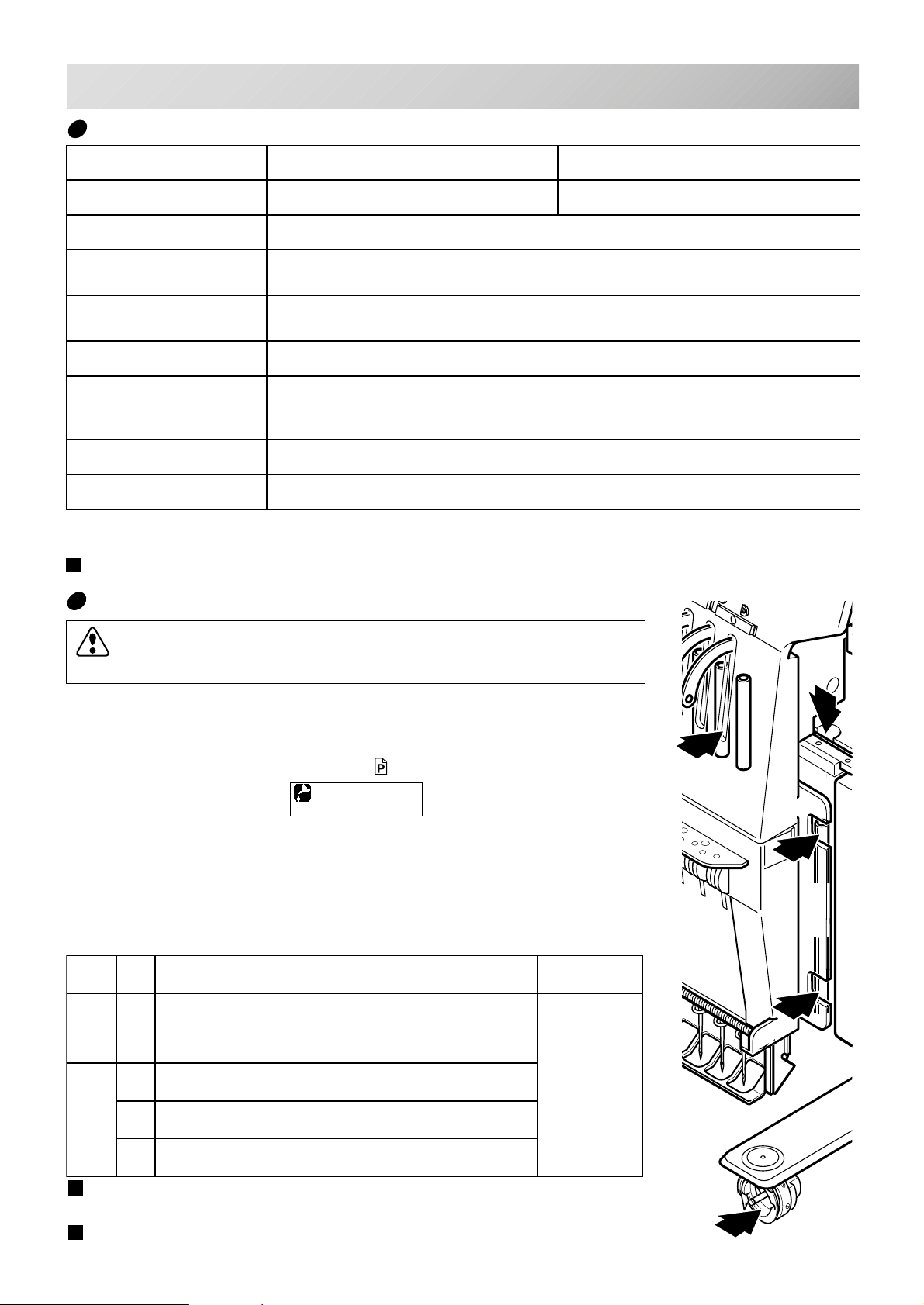
SPECIFICATIONS • MAINTENANCE
2
4
1
2
3
Specifications
egatloV%5+~%01-V511~V001esahp1 %01+~%01-V032~V002esahp1
noitpmusnocyticirtcelEhW022hW022
10-1
ycneuqerF05
noitidnoclatnemnorivnE
noisnemiD
)htpeDxthgieHxhtdiW(
thgieWgK04
)XxY(aerayrediorbmE
yticapacyromeMsehctits000,052
nrettapderetsigeR.tap99
/
zH06
C°04~0erutarepmeT
%58~54erutsioM
"3.92x"92x"5.12,mm547xmm437xmm645
*1 Actual embroidery area will be restricted in accordance with inner frame size.
*2 Actual embroidery area will be restricted in accordance with shape of a cap.
Specifications are subject to change without notice.
Oiling
CAUTION: To prevent accidents.
When taking care of the machine, be sure to remove the plug.
1*.xaM"4.11x"2.11,mm092xmm582)02323-ATPfodleifweS(emarfralubuT
2*.xaM"7x"6.2,mm081xmm76)noitpO(emarfpaclamroN
2*.xaM"4.11x"6.2,mm092xmm76)noitpO(emarfpacediW
The machine will advise you that lubrication is necessary on the basis
of stitch number.
When it is turned on, the machine will display an icon and letter to
indicate that lubrication is necessary.
A B
3-4
Please lubricate the specified oil locations according to the instructions below.
Running the machine without proper oiling will damage the machine.
Lint will gather in and around the rotary hook. Rotary hooks then wear
which will cause the threads to break. Please clean lint with a brush
and run the machine idly for 2 ~ 3 minutes.
kraM.oNliootecalPliodeificepS
A1 koohyratoR
dnahsurbllamsahtiwylthgilsliohtiwetacirbuL(
rennidnaretuoehtneewteblioenihcamgniwes
).strapkoohyrator
B2 rabediugtooferusserP
3tfahsdaeH
gniweS
lioenihcam
4rabeldeeN
When oiling the pressure foot guide bar, please move the head to
the left and set it to needle No. 1.
Too much oil may stain fabrics and threads.
-CS -70
10_1 F201
Page 81
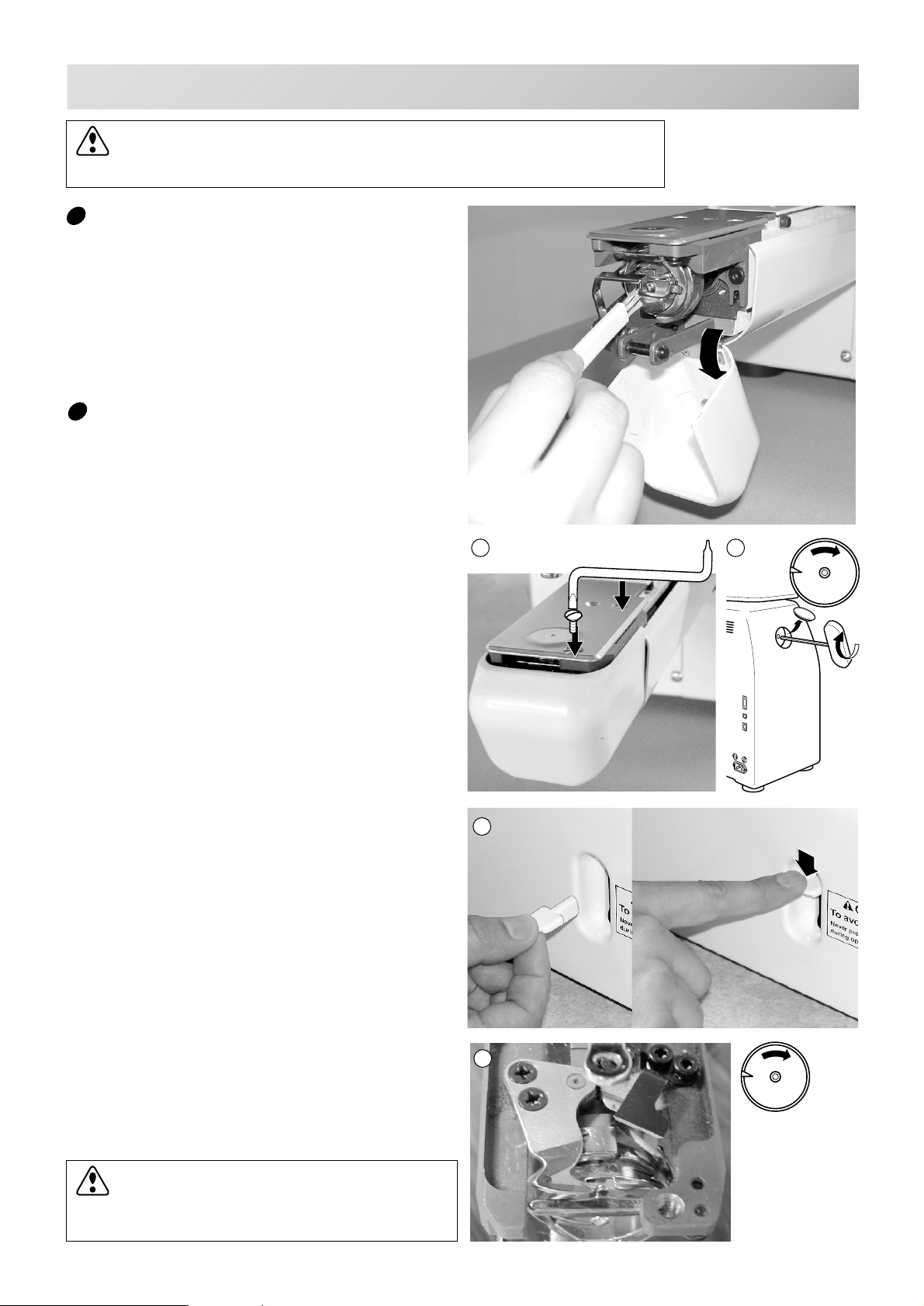
SPECIFICATIONS • MAINTENANCE
CAUTION: To prevent accidents.
When taking care of the machine, be sure to remove the plug.
Cleaning of the rotary hook
If the rotary hook is clogged with waste thread
or dust, it will degrade the stitch quality of the
embroidery or may cause other problems.
For a long sewing life, please keep the rotary
hook clean.
Use the included brush for cleaning the hook.
Cleaning the thread cutting knife
If the thread cutting knife is clogged with waste
thread or dust, the knife will not work correctly.
Please keep the thread cutting knife and device
clean.
10-2
1. Remove set screw (2 pieces) by offset
driver and remove the needle plate.
2. Turn the main shaft toward the arrow mark
until the gauge points to the "C" point by
using the 3 mm hexagonal driver.
3. Insert manual lever and pull down the
manual lever that is in the left hand side of
the machine as you face it.
4. Keep pressing the manual lever and turn
the main shaft toward the arrow mark until it
points to the "L" point.
5. Remove any waste thread and dust from
the thread cutting knife and surrounding
area.
6. Adjust the main shaft until the gauge points
to the "C" point.
Thread cutting knife returns to the original
position.
1 2
C
3
7. Remove manual lever and put the needle
plate back on the bed and attach it with the
screws (2 pieces).
Please do not keep manual lever to knob.
Please take care of manual lever.
CAUTION: To avoid problems.
Never press the manual lever while
the machine is running.
4
L
-CS -71
10_2 G401
Page 82
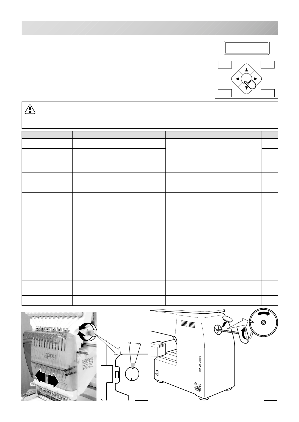
P.FOOT T.CUT
MENU
FORWARD
ENT.
ERRORS AND WHAT TO DO
10-3
If something unusual happens to the machine when running it, please
refer to the following table for troubleshooting solutions. Press the
”ENT.” button on the controller to release any error and correct it ac-
error E-050
C point
cording to the list below.
When errors occur frequently, please contact your dealer.
Automatic errors backup
The machine recovers from some errors (E-050, E-190, E-193) automatically after detecting the error(s) by it self. When the machine does
not recover from the error automatically, Please follow the “Solutions”
below according to the shown number.
CAUTION: To prevent accidents.
In case of "Automatic errors backup", the machine's sudden movement might be caused
without showing errors or messages after its stoppage.
.oN
100draobtiucriClortnocnidetcetedsawytilamronbA
400yromemmetsySredrofotuosiyromemmetsyS
510pirtretrevnIelbuortdetalerrotomgniweS
810tfahsniaMnrutt'nseodtfahsniaM erasevirdrotfahsniamfierusekaM
020tcetedeldeeNeldeeN.detcetedtonsinoitisopeldeeN
120
220
420retneceldeeN.retnecffosinoitisoppotsrabeldeeN
520revoeldeeNehtnignitsixetonrebmuneldeeN
620reffideldeeNtratsdnahsiniffoemittarebmuneldeeN
030hctamsimwolSwoltatnemtsujdadeepsreporpmI
050tniopCstifotuositfahsniamfonoitisoppotS
yalpsiD rorrE snoituloS egaP
notinrutdnaecruosrewopffonruT
ehtdnametsysenihcamehtezilaitinI
epocs(noitisopdexifforetnectates
dnaeldeenfonoitcnuflamgnixifretfA
rabeldeennrut,revelpu-ekatdaerht
epocs(noitisopdexifforetnectates
ehtdnametsysenihcamehtezilaitinI
evomeldeeNtinunoitcelesrabeldeenrofrotoM
.draobtiucric
,tiucrictrohs,rotomgniwesnodaol-revO
tinuevirdrotomfoelbuort
.noitisoppotsstiffositinunoitcelesrab
tiucricgnitcetednoitisopfoelbuorT
draob
.yawflahdeppots
fonoitcnuflamotgniwotnemevomoN
foelbuortrorevelpu-ekatdaerht
.draobtiucricgnitcetednoitisop
.ecalpfotuosinoitisoppotsrabeldeeN
.deificepssawenihcam
otdegnahcsawtI.sreffidnoitarepofo
.enotcerroc
wolebesaercedt'nseoddeepS.deeps
.deepswoltampr001
calp
.niaga
2.giF
.lamron
.deepsenihcam
noitcelesrabeldeennruTtinutievahot
.)evom
1.giF
.)evomt'nseodnoitcelesrab
1.giF
.)evom
1.giF
.deepsenihcam
.woleb2.giFeeS6-01
.dnahhtiwtfahsniamnrutdnarewoptuC
.niaganonrut,dnuofsiytilamronbaonfI
1-11
t'nseodnoitcelesrabeldeenhcihwnihtiw
foretnectatestievahottinunoitceles
eldeenhcihwnihtiwepocs(noitisopdexif
tievahottinunoitcelesrabeldeennruT
t'nseodnoitcelesrabeldeenhcihwnihtiw
1-11
1-11
Turn the needle bar
selection knob to the
marked area with hand.
Marked area
Fig. 1 Fig. 2
C
Turn the disk with
3mm hexagonal
driver clockwise.
-CS -77
10_3 I512
Page 83
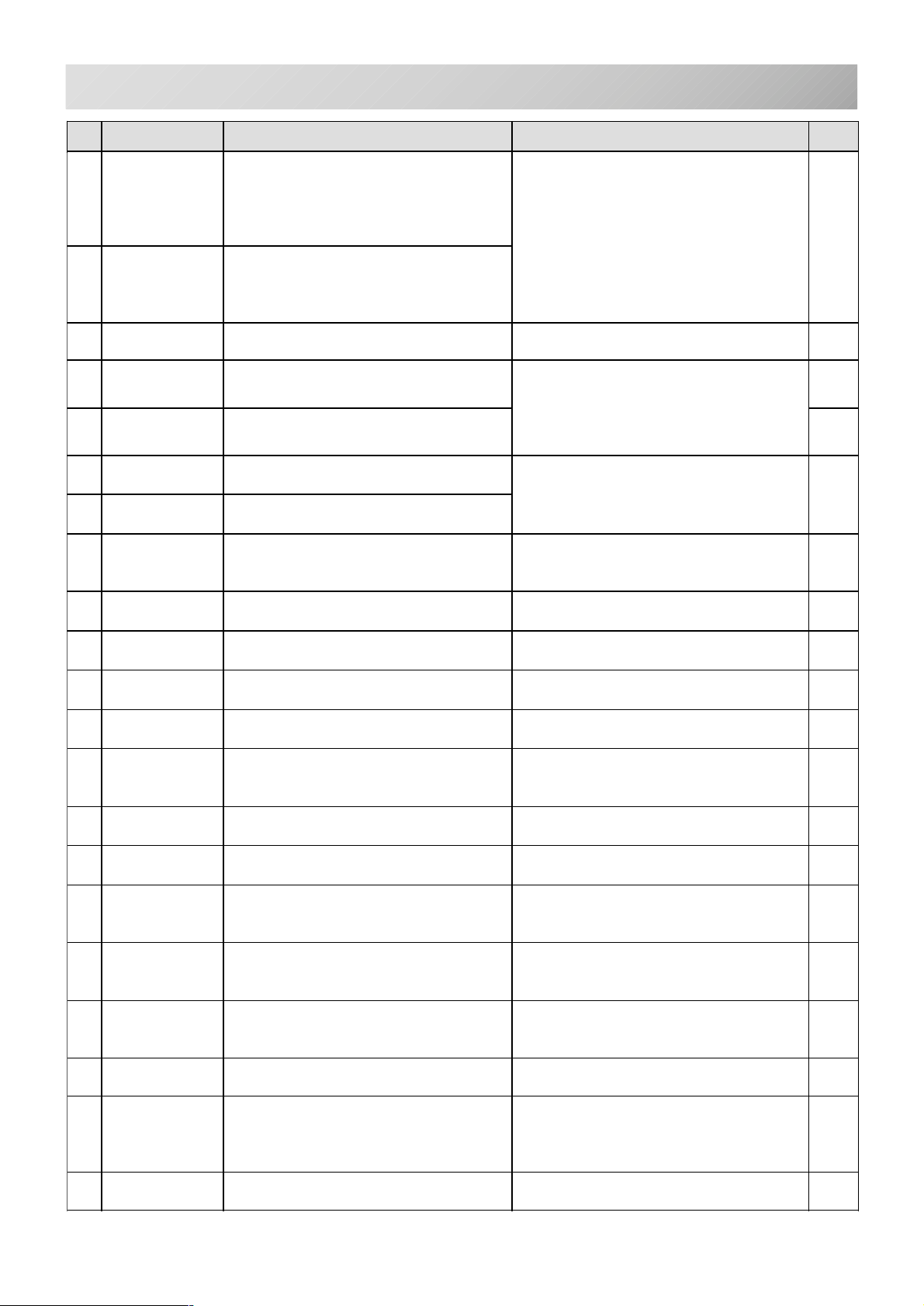
ERRORS AND WHAT TO DO
10-4
.oN
150rosnesLytrid,draobgnitcetedgnimitfoelbuorT
250rosnesCniats,draobgnitcetedgnimitfoelbuorT
550revocpu-ekaT.neposirevocrevelpuekaT.revocrevelpuekatehtesolC
060timilX-edisaeragniwesdnoyebdevomemarF
160timilYaeragniwesdnoyebdevomemarF
090noitpecerssiMfonoitacinummocgnirudderruccororrE
190dnesoN.sdnoces01revorofnitnestondidataD
301tamrofataDyllacitamotuatonnacenihcamehT
yalpsiD rorrE snoituloS egaP
).P.L(]2HP[rosnesotohp
"noitisopeldeentsewoL"fonoitcnuflaM
.draobtiucricgnitcetednorosnes
.etalptilsfotnemtsujdareporpmI
.).P.C(]1HP[rosnesotohpfo
"noitisopegnahcroloC"fonoitcnuflaM
.draobtiucricgnitcetedgnimitnorosnes
.syaw
.esiw-htgnel
.atad
.atadnrettapehtfotamrofehtenimreted
etalptilsehtroytridsirosnesotohP
.rosnesstcatnoc
ehtdnametsysenihcamehtezilaitinI
.deepsenihcam
esuybaeragniwesnihtiwemarfnruteR
.nottubworraehtfo
fostnetnocdnaezisnrettapkcehC
.sgnittes
ehtmorfniagaatadnrettapdaeR
.gninnigeb
.atadnrettapfotamrofatadkcehC
.ylreporptamrofatadteS
1-11
4-5
2-5
401noitcnufssiMdaerotgnimiTatadnrettapt'nseod
.mrofnoc
501noitcnuflauD.snoitcnuf2nahteromsahhctitsenO ehtmorfniagaatadnrettapdaeR
801daerreporpmIrorrena,atadnrettapgnidaerelihW
.derrucco
011llufyromeMyromem,nrettapagnidaerelihW
.yticapacstidedeecxe
111revoegnahCeht,atadnrettapgnidaerelihW
).oNroloc(egnahcrolocfoycneuqerf
.semit052dedeecxe
211rorreataDebotnrettapfoatadnrettaP
.degamadsiderediorbme
411revodIsahyromemnisnrettapforebmunehT
.99fomumixamdehcaer
811revoatadecarTerewatadecartsehctits4201revO
.atadnrettapfognidaergniruddetaerc
021rorreyromeMstnetnocniaterotelbissopmiemacebtI
.yromemfo
031rorredraCaidemyromemfognisopsidfoelbapacnI
.ylsuounitnoc
131ydaertoNyromeMaidem.testonsiyromemfikcehCaidem.tesylreporpsi5-5
daeRatadnrettapehtmorfniaga
.gninnigeb
.gninnigeb
ehtmorfniagaatadnrettapdaeR
gninnigeb.
daerdnasnrettapyrassecennueteleD
.testuoehtmorf
enofoegnahcrolocfoycneuqerfecudeR
.semit052nahtsselotnrettap
dnanrettapeteleDatadnrettapdaer
.niaga
daerdnasnrettapyrassecennueteleD
.gninnibebehtmorfniaga
yrediorbmEothtgnelhctitsmumixamteS
htgnel(m2nihtiwatadnrettapfoaera
.)esiwedis(m2x)esiw
UPC,yltneuqerfsrucconoitidnocsihtfI
.redrofotuosidraobtiucric
.relaeDruoytcatnoC
notinrutdnaecnoecruosrewopffonruT
.niaga
.relaedruoytcatnoc,KOtonfI
4-5
4-5
4-5
8-5
8-5
8-5
331dracdaByromeMaidem.nekorbroreporptonsiyromeMaidemnekorbrodaerebtonnac
yromemaidemtondracyromemro
.dezilaitini
.relaeDruoytcatnoC
141emandnuoftoN.dnuoftonsinrettapdetangiseDyromeMaidem.tcerroctonsi5-5
-CS -78
10_4 H701
5-5
Page 84

ERRORS AND WHAT TO DO
10-5
.oN
091edalbtuC.noitisoppotstatonsiefinktucdaerhT.wolebsnoitcurtsniehtwolloF7-01
391rehctaCnoitisopstiffosikoohhctacdaerhT
yalpsiD rorrE snoituloS egaP
.wolebelpmasxeehtwollofesaelP
tonsinoitisoptcetedothctiwstimiL
."FFO"
.yletelpmoc
.daerhttuctonseodtifikcehC.1
ehtnruterdnatituc,tuctonsidaerhtfI
.noitisoplamronstiotkoohhctacdaerht
hctacdaerhtfikcehc,tucerasdaerhtfI.2
noitisopstiotdenrutersahdaehnokooh
8-01
-CS -74
10_5 D609
Page 85
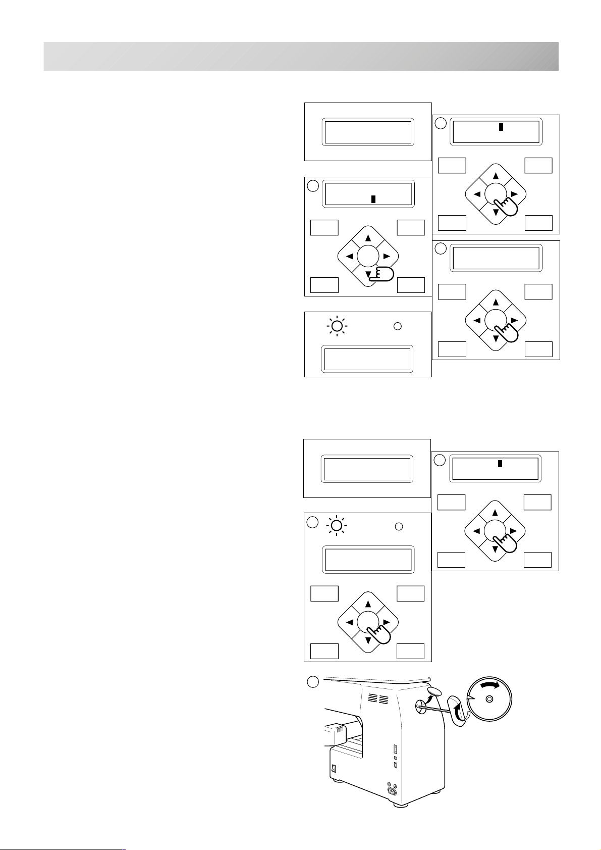
ERRORS AND WHAT TO DO
P.FOOT T.CUT
MENU
FORWARD
ENT.
2
FORWARD
P.FOOT T.CUT
MENU
ENT.
3
10-6
What to do for “Stop position of main shaft is out of its place (error E-050)”
1. Press the “ENT.” button when showing
[ERR].
2. Press the “Down” arrow button until the
cursor points to “Auto”.
3. Press the “ENT.” button.
The main shaft turns 2 to 3 times and returns to
a stop position (“C” point ) automatically.
The display returns to drive mode.
error E-050
C point
[ERR] Manual
Auto
G
ID:10 Nd: 1
1240
1
[ERR] Manual
Auto
MENU
FORWARD
ENT.
P.FOOT T.CUT
3
Caution !! main
shaft truns
MENU
FORWARD
ENT.
P.FOOT T.CUT
When you cannot clear by the method above (Auto)
1. Press the “ENT.” button when showing
[ERR].
2. Press the “ENT.” button.
The error status is released and the display
shows “drive mode”.
3. Remove the cap over the small hole in the
rear of the machine. Using the 3 mm hexagonal driver, Please turn the main shaft
and adjust it to the “C” point.
error E-050
C point
2
G
ID:10 Nd: 1
1240
1
[ERR] Manual
Auto
MENU
FORWARD
ENT.
P.FOOT T.CUT
C
-CS -75
10_6 G401
Page 86
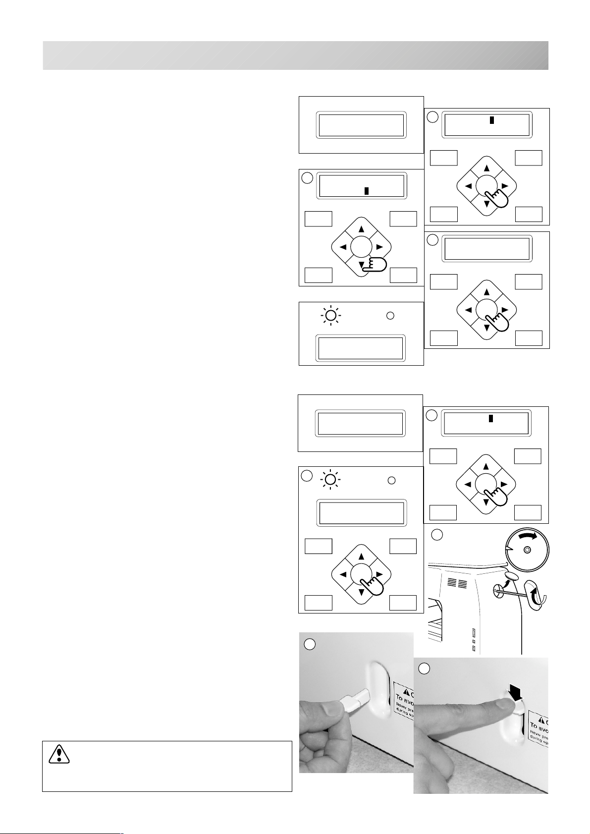
ERRORS AND WHAT TO DO
P.FOOT T.CUT
MENU
FORWARD
ENT.
2
FORWARD
P.FOOT T.CUT
MENU
ENT.
10-7
What to do for "Thread cut knife is not at the stop position (error E-190)"
1. Press the "ENT." button when showing
[ERR].
error E-190
Cut blade
2. Press the “Down” arrow button until the
cursor points to "Auto".
[ERR] Manual
Auto
3. Press the "ENT.” button.
The main shaft turns 2 to 3 times and the thread
cutting knife returns to the stop position.
The display returns to the drive mode.
G
ID:10 Nd: 1
1240
When you cannot clear by the method above (Auto)
1
[ERR] Manual
Auto
MENU
FORWARD
ENT.
P.FOOT T.CUT
3
Caution !! main
shaft truns
MENU
FORWARD
ENT.
P.FOOT T.CUT
1. Press the "ENT." button when showing
[ERR].
2. Press the "ENT." button.
The error status is released and the screen
shows "drive mode".
3. Remove the cap over the small hole in the
rear of the machine. Using the 3 mm hexagonal driver, Please turn the main shaft
and adjust it to the "C" point.
4. Insert manual lever that is in the left hand
side of the machine as you face it.
5. While pressing the manual lever, turn the
main shaft a complete revolution and set it
to the “C” point.
The knife will return to it’s proper position.
error E-190
Cut blade
2
G
ID:10 Nd: 1
1240
4
1
[ERR] Manual
Auto
MENU
FORWARD
ENT.
P.FOOT T.CUT
3
C
5
6. Remove the manual lever.
Please do not keep manual lever to knob.
Please take care of manual lever.
CAUTION: To avoid problems.
Never press the manual lever while
the machine is running.
-CS -76
10_7 G401
Page 87
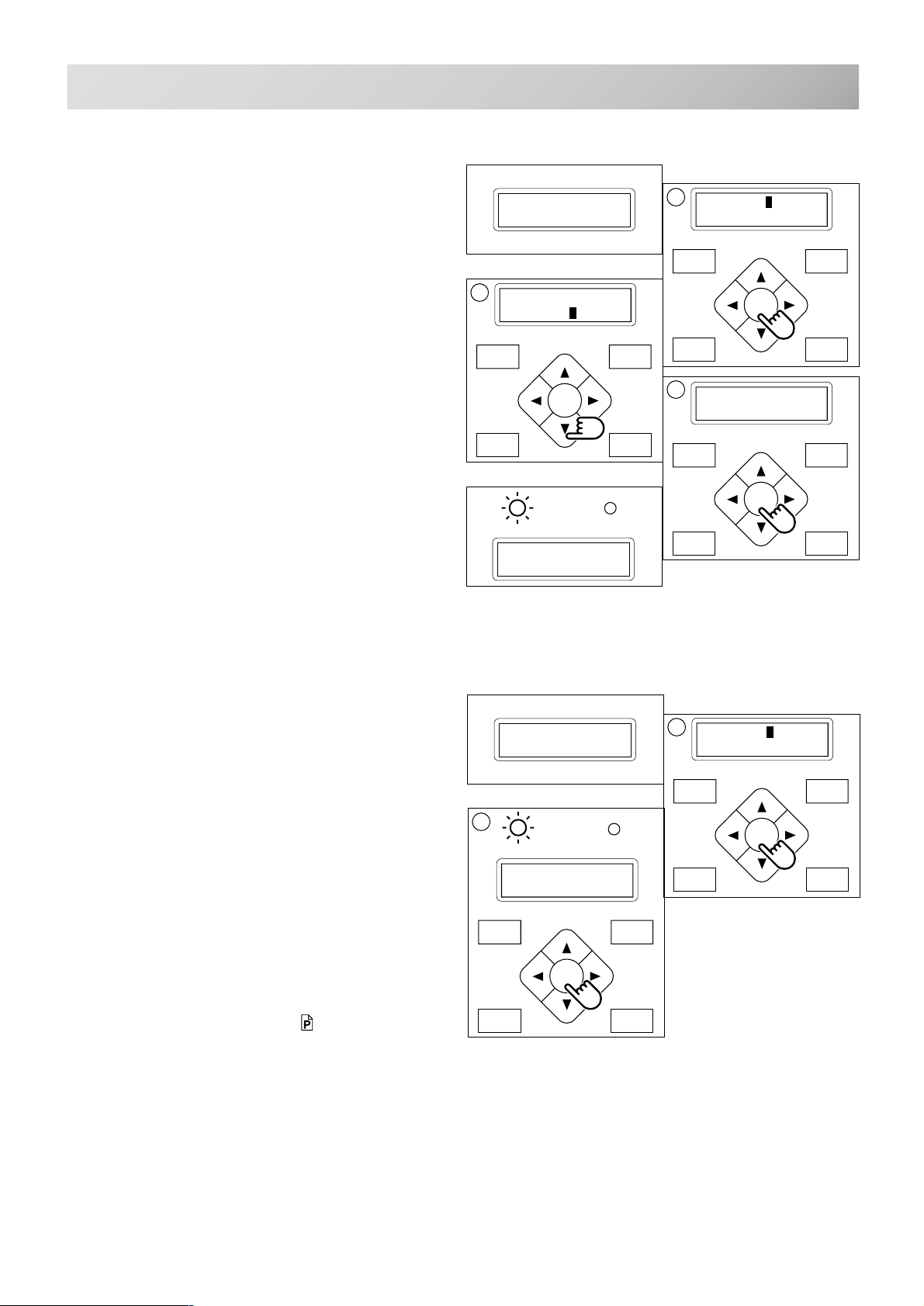
ERRORS AND WHAT TO DO
P.FOOT T.CUT
MENU
FORWARD
ENT.
FORWARD
P.FOOT T.CUT
MENU
ENT.
2
10-8
What to do
for "Thread catch hook is off its position (error E-193)"
1. Press the "ENT." button when showing
[ERR].
2. Press the “Down” arrow button until the
cursor points to "Auto".
3. Press "ENT.” button.
The thread catch hook returns to the original
position.
The display returns to drive mode.
error E-193
Catcher
2
[ERR] Manual
Auto
MENU
FORWARD
ENT.
P.FOOT T.CUT
G
ID:10 Nd: 3
1240
1
[ERR] Manual
Auto
MENU
FORWARD
ENT.
P.FOOT T.CUT
3
Caution !!
Catcher moves
MENU
FORWARD
ENT.
P.FOOT T.CUT
When you cannot clear by the method above (Auto)
1. Press the "ENT." button when showing
[ERR].
2. Press the "ENT.” button.
The Error status is cleared and the display
shows "drive mode".
3. Refer to the page (ERRORS AND WHAT
TO DO), locate the cause that the hook
does not return to the original position, and
follow the steps outlined.
10-5
error E-193
Catcher
G
ID:10 Nd: 3
1240
1
[ERR] Manual
Auto
-CS -77
10_8 D610
Page 88
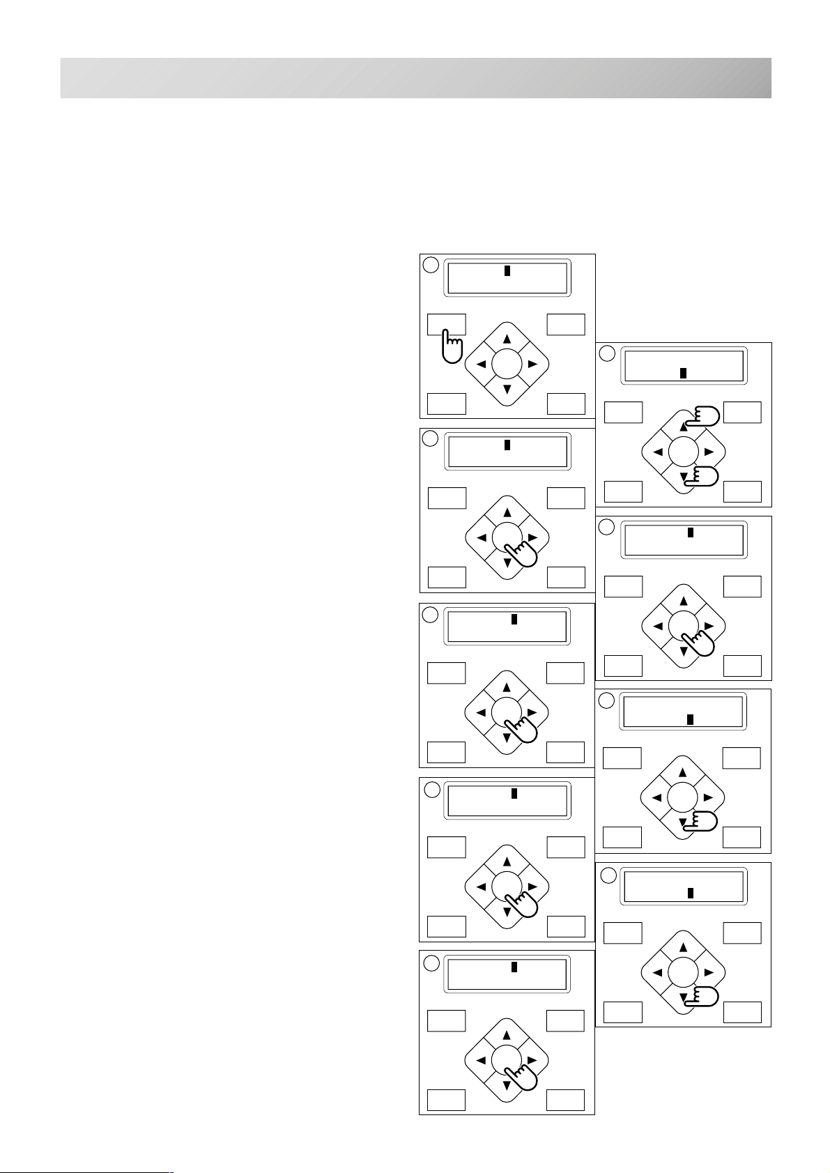
INITIALIZING MACHINE SETTINGS
P.FOOT T.CUT
MENU
FORWARD
ENT.
P.FOOT T.CUT
MENU
FORWARD
ENT.
3
5
P.FOOT T.CUT
MENU
FORWARD
ENT.
7
P.FOOT T.CUT
MENU
FORWARD
ENT.
11-1
If you have E-18, E-30, E-51 or E-52 while sewing, Please try initializing the machine settings.
You will always need to initialize the machine speed when you initialize the settings.
Initialize of machine system
1. Press the "MENU" button until [MENU] is
showing when the machine is stopped.
2. Press the ”Up” or “Down” arrow button until
the cursor points to "Other".
1
[MENU] Pattern
Needle
2
[MENU] Letter
Other
3. Press the "ENT." button when showing
[OTHER].
4. Press the "ENT." button.
5. Press the "ENT." button.
Choose either “Cancel” or “OK”.
6. Press the “Down” arrow button and move
the cursor to "OK".
Press the "ENT." button to cancel.
The display will return to drive mode.
[OTHER] Setup
Clock
MENU
FORWARD
ENT.
P.FOOT T.CUT
[SYSTEM] Cancel
OK
[SETUP] System
Speed
MENU
FORWARD
ENT.
P.FOOT T.CUT
4
[SETUP] System
Speed
MENU
FORWARD
ENT.
P.FOOT T.CUT
6
[SYSTEM] Cancel
OK
MENU
FORWARD
ENT.
7. Press the "ENT." button.
Formatting of the machines systems are carried
out.
Initializing of machine speed
8. Press the “Down” arrow button until the
cursor points to "Speed".
9. Press the "ENT." button.
Choose either “Cancel” or “OK”.
9
[SPEED] Cancel
OK
P.FOOT T.CUT
8
[SETUP] System
Speed
MENU
FORWARD
ENT.
P.FOOT T.CUT
-CS -78
11_1 D610
Page 89
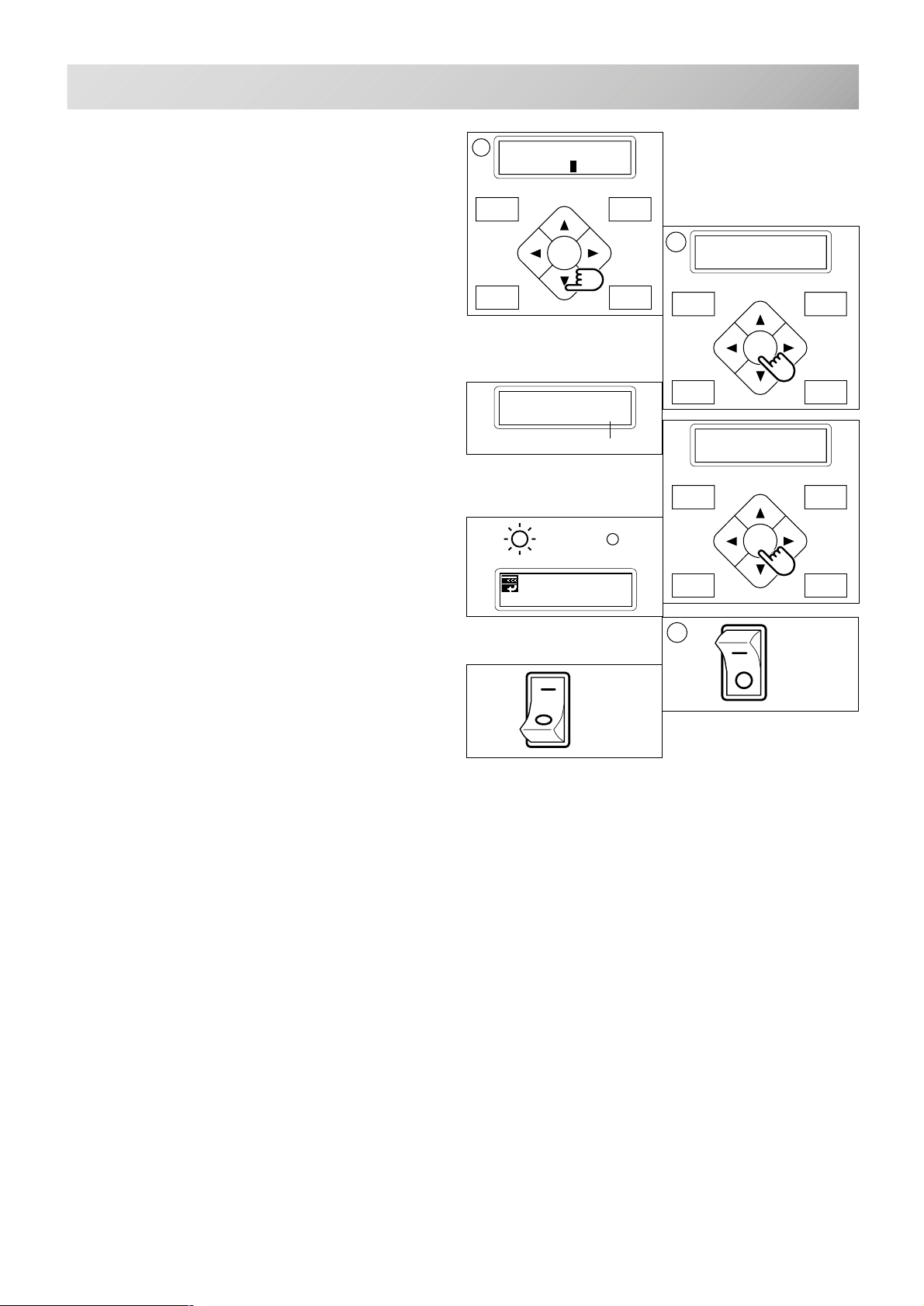
INITIALIZING OF MACHINE SETTINGS
P.FOOT T.CUT
MENU
FORWARD
ENT.
P.FOOT T.CUT
MENU
FORWARD
ENT.
P.FOOT T.CUT
MENU
FORWARD
ENT.
10
11-2
10.To initialize, press the ”Down” arrow button
and move cursor to "OK".
Press the "ENT." button to cancel.
The display returns to drive mode.
11.Press the "ENT." button.
The machine will show a notice then start turning
the main shaft automatically and the speed will
slowly increase.
The speed will increase to maximum and then
stop automatically and indicate " -- Complete --".
[SPEED] Cancel
OK
[SPEED]
1000
Revolution speed
G
ID: 5 Nd: 4
BIRD
11
Caution !! main
shaft truns
[SPEED]
-- Complete --
12.Turn off the power switch and turn on the
power switch again.
ON
OFF
12
ON
OFF
-CS -79
10_2 D424
Page 90
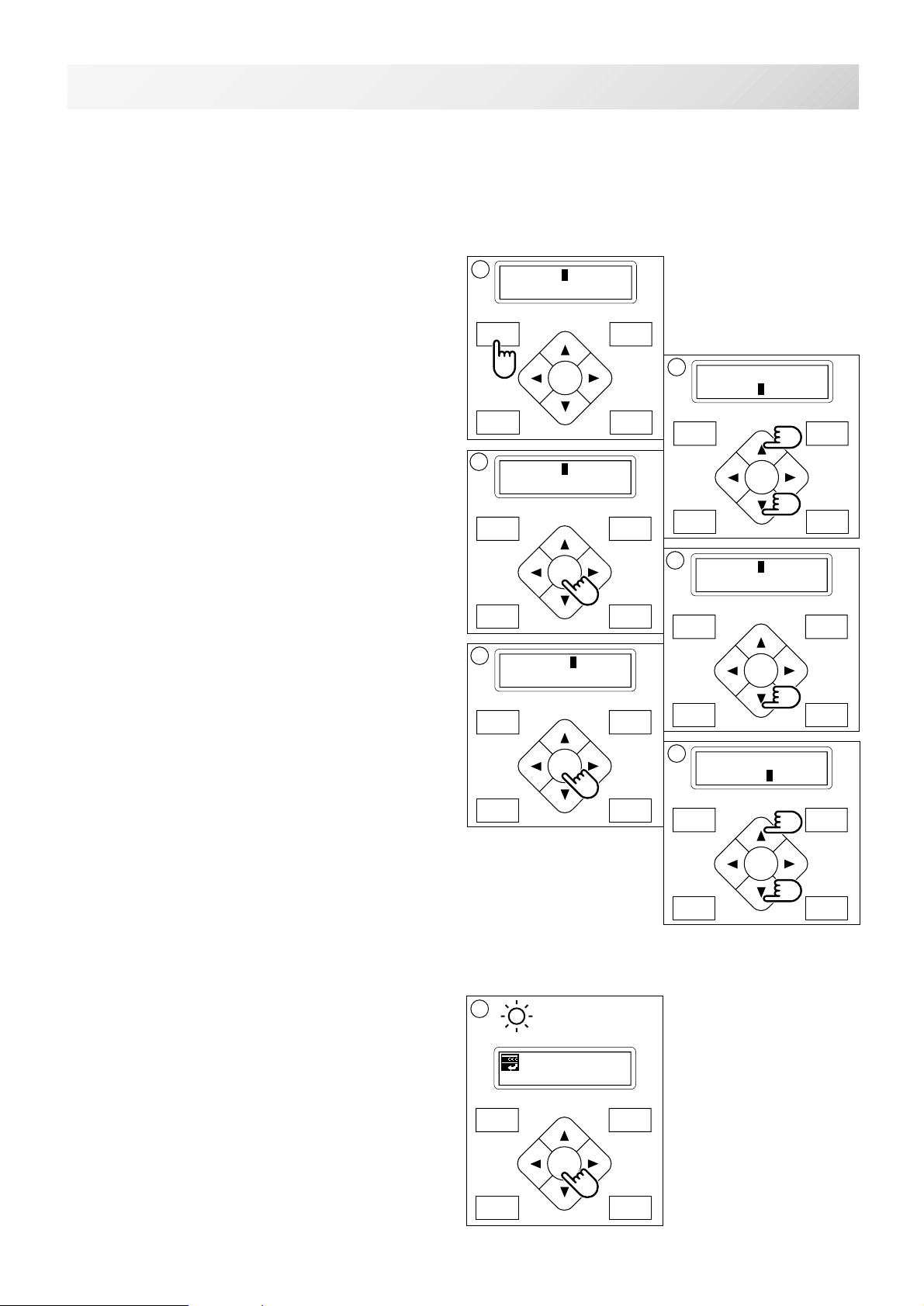
P.FOOT T.CUT
MENU
FORWARD
ENT.
P.FOOT T.CUT
MENU
FORWARD
ENT.
CHANGE OF THREAD BREAK DETECTION
3
Sensitivity selection of the thread break detect sensor.
You can select the sensitivity.
By default it is set to "Normal".
11-3
1. Press the "MENU" button until [MENU] is
showing when the machine is stopped.
2. Press the ”Up” or “Down” arrow button until
the cursor points to "Other".
3. Press the "ENT." button when showing
[OTHER].
4. Select "Detect" by press down "Arrow"
button.
5. Press the "ENT." button.
1
[MENU] Pattern
Needle
MENU
FORWARD
ENT.
P.FOOT T.CUT
[OTHER] Setup
Clock
MENU
FORWARD
ENT.
P.FOOT T.CUT
5
[DETECT] Normal
Quick1
MENU
FORWARD
2
[MENU] Letter
Other
4
[OTHER] Detect
MENU
FORWARD
ENT.
P.FOOT T.CUT
6. Pressing the “Up” or “Down” arrow button,
moves the cursor to the selected sensitivity.
Off : Detect system off
Slow3 : Lower sensitivity detection 3
Slow2 : Lower sensitivity detection 2
Slow1 : Lower sensitivity detection 1
Normal: Standard sensitivity detection
Quick1: High sensitivity detection 1
Quick2: High sensitivity detection 2
Quick3: High sensitivity detection 3
7. Press the "ENT." button.
Make your change and return to drive mode.
ENT.
P.FOOT T.CUT
7
G
ID:10 Nd: 4
BIRD
6
[DETECT] Off
Slow3
MENU
FORWARD
ENT.
P.FOOT T.CUT
-CS -88
11_3 K101
Page 91
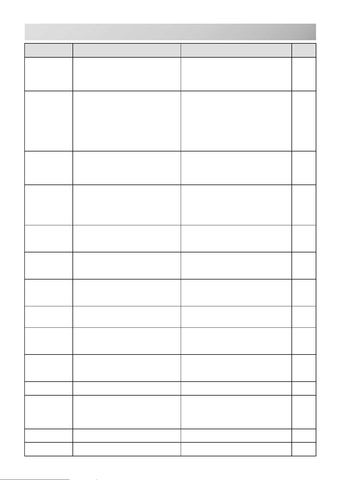
HELPFUL HINTS
MELBORP ESUAC NOITCERROC EGAP
12-1
tratstonseoD
gnirediorbme
gnisserpnehw
"TRATS"
nottub
daerhtreppU
skaerb
.ytilauqdaerhtrooP
koohyrD
.enocdaerht
daerhtrewoL
skaerb
.koohehtnotriD
koohyrD
kaerbdaerhT
pusthgilpmal
daerhtetipsed
gniebton
eslaF(nekorb
)skaerbdaerht
spiksenihcaM
sehctits
srekcupcirbaF.ylreporptonenihcaM
.eldeentnulB
enihcaM
esoolsekam
rosehctits
spool
noisnetrooP
ecnalab
koohyrD
ngisedrooP
noitartsiger
.ylreporp
skaerbeldeeN.eldeentnulbrotneB
.gnipoohrooP
snurenihcaM
ytluciffidhtiw
lliwenihcaM
nurton
nonruttonlliw.nottubycnegremegnikcoL.nottubycnegremefokcolesaeleR7-3
.teltuo
.gnikaerb
.eldeentnulbrotneB
.lairetamcitsalegnisU
.ecarkoohehtnotriD.koohyratorehtnaelC
.neposirevocrevelpuekaT.revocrevelpuekatehtesolC4-01
.dedaerhtylreporptonenihcaM
.yltcerrocnidetresnieldeeN
.thgitootnoisnetdaerhT
ynitsuounitnocrosehctitsytpmE
.atadngisednisehctits
reppunanidelgnatsidaerhT
.yltcerrocnidedaerhtnibboB
.llufootroylnevenudnuownibboB
.thgitootnoisnetdaerhT
gnissaptonsidaerhtreppU
.rellorgnitcetedehtdnuora
.yltcerrocnidetresnieldeeN
.eldeenfoezistcerrocnI
.yltcerrocnidedaerhtnibboB
.thgitootnoisnetdaerhT
.yltcerrocnidedaerhtnibboB
.dedaerhtylreporptonenihcaM
.ylreporpdetsujdatonnoisneT
.yltcerrocnidedaerhtnibboB
.dedaerhtylreporptonenihcaM
.yltcerrocdepoohtoncirbaF
enihcamotnidellatsnitonpooH
.tcerrocnignitteseldeeN
.lairetamtsniagaeldeennihT
lacirtceleotnideggulptondroC
.nodenruttonsihctiwsrewoP
siesufecruosrewopehT
.yltcerroc
.cirbaf
gniliOyratoreht.kooh
.enihcamdaerht-eR
.eldeentresni-eR
.noisnetdaerhttsujdaeR
.koohyratorehtgniliO
.niagaatadngiseddaer
.daerhtehtelgnat-nU
.nibbobehtdaerht-eR
.nibbobehtdniweR
.noisnetdaerhttsujdaeR
.koohehtnaelC
.koohotgniliO
.eldeentresni-eR
.eldeenwentresnI
.enihcamdaerht-eR
.nibbobehtdaerht-eR
.eldeenwentresnI
.noisnetdaerhttsujdaeR
.nibbobehtdaerht-eR
.enihcamdaerht-eR
.noisnetdaerhttsujdaeR
.nibbobehtdaerht-eR
.enihcamdaerht-eR
.koohotgniliO
.yltcerrocgnippoohteS
.gnikcabtcerrocesU
.yltcerrocpoohteS
.eldeenwentresnI
.eldeentresni-eR
.eldeenrekcihtotegnahC
.cirbafpooh-eR
.teltuootniyllufgulptresnI
.hctiwsehtnonruT
.enowenaot)A6(
6-4
1-4
1-8
.daerhtytilauqdooghtiwecalpeR
1-01
nehtnoitcnufpeewshctitsnonruT
daerhtreppuehtdaerhtesaelP
rofeldeenezistcerrocesoohC
esufecruosrewopehtegnahC
2-5
5-4
4-4
4-4
2-01
1-01
7-4
1-4
1-4
2-4
6-4
5-4
1-4
1-8
5-4
6-4
1-8,5-4
5-4
6-4
1-01
4-7,2-6
2-6
5-7,3-6
1-4
1-4
2-4
2-01
1-01
5-3
1-3
eestonnaC
unem
.tsartnocfognittesgnorW.tsartnocDCLtsujdaesaelP5-3
-CS -81
12_1 D610
Page 92

EMBROIDER Y TERMS
12-2
Color number
The Needle number (thread color) to be sewn can
be set to each color number. For example, if the
pattern is divided by a color change function at 2
places, 3 color numbers exist in the pattern.
When the needle number is set to it’s respective
color number, the pattern is embroidered in 3
colors.
Memory pattern
Patterns stored in memory.
Start point of the frame
This is the point where the frame begins to move
before starting embroidery.
Trace back
This is to move the frame and memory pattern in
the reverse direction of sewing.
Trace forward
This is to move the frame and memory pattern
toward the sewing direction.
Original point
The frame position where the machine embroiders
the pattern from the beginning is automatically
registered in the machine as the original point.
Reverse
The pattern can be reversed like a object appearing
in a mirror.
Communication speed
The communication speed between the machine
and The pattern data output device (PC) if they
are connected with a serial port. If the communication speed value becomes bigger, the speed
becomes faster, however in this case a communication error could happen more easily. If you have
a communication error often, decrease this value.
Memory media
What saves design data by things, such as
memory card and a USB memory.
Data format
This is the format that the tape pattern data is
converted into.
Color change stop
When color change stop is set to a color number,
the machine embroiders the set color number and
stops.
Zero stitch
This is a stitch that the move distance of both
sidewise and lengthwise is "0" and the needle
lands in the same position.
Conversion
The Angle of a pattern can be changed by 90
degree.
-CS -87
12_2 H701
Page 93
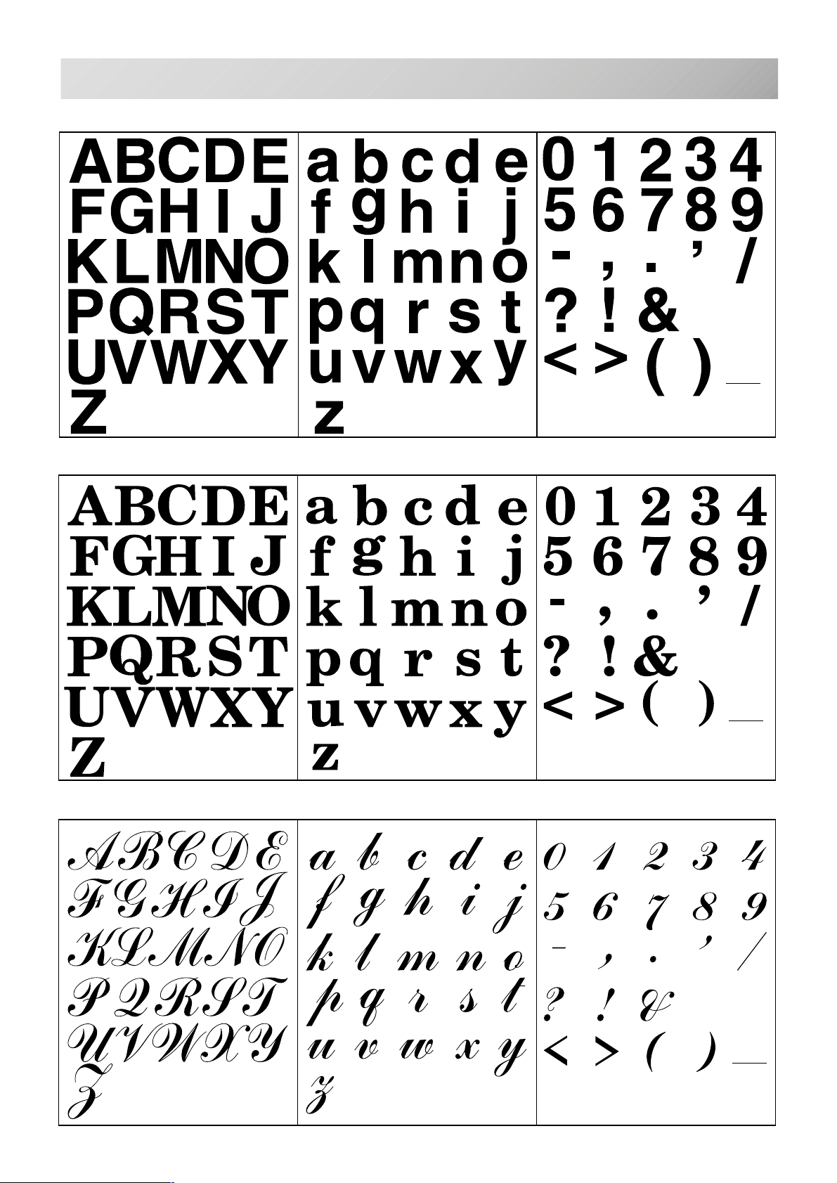
BUILT-IN FONT LIST
Style 1
Style 2
12-3
Style 3
-CS -83
12_2 D424
Page 94

HEAD OFFICE 9-16, 5-chome, Miyamachi, Yamagata-City 990-0057,
Japan
Phone: 023-623-7111 FAX: 023-623-2654
TOKYO OFFICE 2-9-5, T aito, Taito-Ku, Tokyo 110-0016, Japan
Phone: 03-3834-0711 Telex: 265-5482
FAX: 03-3835-8917 Cable: HAPPYSEW TOKYO
HAPPY
INDUSTRIAL
GmbH
Am Kuemmerling, 10-12
55294 Bodenheim, (Mainz)
Germany
Phone: 06135-8101 FAX. 06135-3995
J428E
 Loading...