

Page 1

NETWORK CAMERA
User Manual
SNV-6013
Page 2

Network Camera
User Manual
Copyright
©201
4 Samsung Tec hwin Co., Ltd . All right s reserve d.
Trad em ark
The name of thi s product is the reg istered tradema rk of Samsung Techwin C o., Ltd.
Other trad emarks mention ed in this manual are t he registered trad emark of their res pective compan y.
Restriction
Samsung Techwi n Co., Ltd shall reser ve the copyrigh t of this document. U nder no circumst ances, this docu ment shall
be reproduc ed, distribute d or changed, par tially or wholly, wit hout formal auth orization of Sa msung Techwin.
Disclaimer
Samsung Techwi n makes the best to ve rify the integr ity and correc tness of the conte nts in this documen t, but no
formal guar antee shall be provi ded. Use of this do cument and the subs equent results sh all be entirely on the u ser’s own
responsib ility. Samsung Techwi n reserves the ri ght to change the con tents of this docu ment without pri or notice.
Design an d specificat ions are subjec t to change wit hout prior not ice.
The defau lt password c an be exposed to a h acking threa d so it is recommen ded to change th e password
after in stalling the p roduct.
Note that t he security a nd other relat ed issues caus ed by the unchan ged password s hall be respon sible
for the user.
is the regist ered logo of Samsun g Techwin Co., Ltd.
Page 3
overview
IMPORTANT SAFETY INSTRUCTIONS
1. Read these instructions.
2. Keep these instructions.
3. Heed all warnings.
4. Follow all instructions.
5. Do not use this apparatus near water.
6. Clean only with dry cloth.
7. Do not block any ventilation openings, Install in accordance with the manufacturer’s
instructions.
8. Do not install near any heat sources such as radiators, heat registers, stoves, or other
apparatus (including amplifiers) that produce heat.
9. Do not defeat the safety purpose of the polarized or grounding-type plug. A polarized
plug has two blades with one wider than the other. A grounding type plug has two
blades and a third grounding prong. The wide blade or the third prong are provided for
your safety. If the provided plug does not fit into your outlet, consult an electrician for
replacement of the obsolete outlet.
10. Protect the power cord from being walked on or pinched particularly at plugs,
convenience receptacles, and the point where they exit from the apparatus.
11. Only use attachments/ accessories specified by the manufacturer.
12. Use only with the cart, stand, tripod, bracket, or table specified by
the manufacturer, or sold with the apparatus. When a cart is used,
use caution when moving the cart/apparatus combination to avoid
injury from tip-over.
13. Unplug this apparatus during lighting storms or when unused for
long periods of time.
14. Refer all servicing to qualified service personnel. Servicing is required when the
apparatus has been damaged in any way, such as power-supply cord or plug is
damaged, liquid has been spilled or objects have fallen into the apparatus, the apparatus
has been exposed to rain or moisture, does not operate normally, or has been dropped.
● OVERVIEW
English _3
Page 4
overview
WARNING
TO REDUCE THE RISK OF FIRE OR ELECTRIC SHOCK, DO NOT EXPOSE
THIS PRODUCT TO RAIN OR MOISTURE. DO NOT INSERT ANY METALLIC
OBJECT THROUGH THE VENTILATION GRILLS OR OTHER OPENNINGS
ON THE EQUIPMENT.
Apparatus shall not be exposed to dripping or splashing and that no objects
filled with liquids, such as vases, shall be placed on the apparatus.
To prevent injury, this apparatus must be securely attached to the Wall/ceiling
in accordance with the installation instructions.
CAUTION
CAUTION
RISK OF ELECTRIC SHOCK.
DO NOT OPEN
CAUTION
REFER SERVICING TO QUALIFIED SERVICE PERSONNEL.
: TO REDUCE THE RISK OF ELECTRIC SHOCK.
DO NOT REMOVE COVER (OR BACK).
NO USER SERVICEABLE PARTS INSIDE.
EXPLANATION OF GRAPHICAL SYMBOLS
The lightning flash with arrowhead symbol, within an
equilateral triangle, is intended to alert the user to the
presence of “dangerous voltage” within the product’s
enclosure that may be of sufficient magnitude to constitute a
risk of electric shock to persons.
The exclamation point within an equilateral triangle is intended
to alert the user to the presence of important operating
and maintenance (servicing) instructions in the literature
accompanying the product.
4_ overview
Page 5

Class construction
An apparatus with CLASS construction shall be connected to a MAINS
socket outlet with a protective earthing connection.
Battery
Batteries(battery pack or batteries installed) shall not be exposed to excessive
heat such as sunshine, fire or the like.
Disconnection Device
Disconnect the main plug from the apparatus, if it’s defected. And please call
a repair man in your location.
When used outside of the U.S., it may be used HAR code with fittings of
an approved agency is employed.
CAUTION
Risk of explosion if battery is replaced by an incorrect type.
Dispose of used batteries according to the instructions.
These servicing instructions are for use by qualified service personnel only.
To reduce the risk of electric shock do not perform any servicing other than
that contained in the operating instructions unless you are qualified to do so.
The CVBS out terminal of the product is provided for easier installation, and is
not recommended for monitoring purposes.
Please use the input power with just one camera and other devices must not
be connected.
The ITE is to be connected only to PoE networks without routing to the
outside plant.
● OVERVIEW
English _5
Page 6

overview
Please read the following recommended safety precautions carefully.
Do not place this apparatus on an uneven surface.
Do not install on a surface where it is exposed to direct sunlight, near
heating equipment or heavy cold area.
Do not place this apparatus near conductive material.
Do not attempt to service this apparatus yourself.
Do not place a glass of water on the product.
Do not install near any magnetic sources.
Do not block any ventilation openings.
Do not place heavy items on the product.
User’s Manual is a guidance book for how to use the products.
The meaning of the symbols are shown below.
Reference : In case of providing information for helping of product’s usages
Notice : If there’s any possibility to occur any damages for the goods and
human caused by not following the instruction
Please read this manual for the safety before using of goods and keep it in
the safe place.
6_ overview
Page 7

CONTENTS
OVERVIEW
3
INSTALLATION &
CONNECTION
15
NETWORK CONNECTION
AND SETUP
22
3 Important Safety Instructions
9 Product Features
10 Recommended PC Specifications
10 Recommended Micro SD/
SDHC/SDXC Memory Card
Specifications
11 NAS recommended specs
11 What’s Included
13 At a Glance
15 Installation
19 Inserting/Removing a Micro SD
Memory Card
20 Memory Card Information
(Not Included)
21 Connecting with other Device
22 Connecting the Camera Directly
to Local Area Networking
23 Connecting the Camera Directly
to a DHCP Based DSL/Cable
Modem
24 Connecting the Camera Directly
to a PPPoE Modem
25 Connecting the Camera to a
Broadband Router with the
PPPoE/Cable Modem
26 Buttons used in IP Installer
27 Static IP Setup
31 Dynamic IP Setup
32
Port Range Forward (Port Mapping)
Setup
34 Connecting to the Camera from a
Shared Local PC
34 Connecting to the Camera from a
Remote PC via the Internet
● OVERVIEW
English _7
Page 8

overview
WEB VIEWER
35
SETUP SCREEN
52
APPENDIX
107
35 Connecting to the Camera
37 Password setting
37 Login
38 Installing Silverlight Runtime
41 Installing STW WebViewer Plugin
43 Using the Live Screen
45 Playing the recorded video
52 Setup
52 Video Setup
68 Network Setup
79 Event Setup
98 System Setup
107 Specification
112 Product Overview
113 Troubleshooting
115 Open Source Announcement
8_ overview
Page 9

PRODUCT FEATURES
• Dustproof/Waterproof (IP66)
The dustproof and waterproof design makes you feel at ease when installing the product
outdoors or exposing it to rain.
• Full HD Video Quality
• Multi-Streaming
This network camera can display videos in different resolutions and qualities
simultaneously using different CODECs.
• Alarm
When an event occurs, the related image is sent to the email address registered by a user
to the FTP server or saved in a micro SD card or the NAS.
• Web Browser-based Monitoring
Using the Internet web browser to display the image in a local network environment.
• Tampering Detection
Detects tempering attempts on video monitoring.
• Motion Detection
Detects motion from the camera’s video input.
• Intelligent Video Analysis
Analyzes video to detect logical events of specified conditions from the camera’s video
input.
• Face Detection
Detects faces from the camera’s video input.
• Smart codec
A clearer version of image of the area set by a user is transmitted.
• Auto Detection of Disconnected Network
Detects network disconnection before triggering an event.
• ONVIF Compliance
This product supports ONVIF Profile-S.
For more information, refer to www.onvif.org.
● OVERVIEW
English _9
Page 10

overview
RECOMMENDED PC SPECIFICATIONS
• CPU : Intel Core 2 Duo 2.4 GHz or higher (for using 1920x1080 30 fps)
Intel Core i7 2.8 GHz or higher (for using 1920x1080 60 fps)
Web Plug-in is optimized to SSE 4.1 Instruction Set.
• Resolution :
• RAM : 2GB or higher
• Supported OS : Windows XP / VISTA / 7 / 8, MAC OS X
• Supported Browser : Microsoft Internet Explorer (Ver.
Mozilla Firefox (Ver. 9~19), Google Chrome (Ver. 15~25),
Apple Safari (Ver. 6.0.2(Mac OS X 10.8, 10.7 only), 5.1.7)
• Video Memory : 256MB or higher
RECOMMENDED MICRO SD/SDHC/SDXC MEMORY CARD
SPECIFICATIONS
• 4GB ~ 64GB
• For your camera, we recommend you use a memory card from the following
manufacturers:
Micro SD/SDHC/SDXC Memory Card : Sandisk, Transcend
• For the framerate below 30 fps, it is recommended to use the specification memory card
of Class 6 or higher.
• For the framerate over 31 fps, it is recommended to use the specification memory card of
Class 10 UHS or higher.
1280X1024 pixels or higher (32 bit color)
10.7
7~10),
Windows 8 is supported only in the Desktop mode.
Neither a beta test version unlike the version released in the company website nor the developer version will
be supported.
For IPv6 connection, Window 7 or higher is recommended.
For Mac OS X, only the Safari browser is supported.
If the driver of the video graphic adapter is not installed properly or is not the latest version, the
J
video may not be played properly.
For a multi-monitoring system involving at least 2 monitors, the playback performance can be
deteriorated depending on the system.
10_ overview
Page 11
NAS RECOMMENDED SPECS
• Recommended capacity : 200GB or higher is recommended.
• Simultaneous access : One unit of NAS can accept a maximum of sixteen camera
accesses.
• For this camera, you are recommended to use a NAS with the following manufacturer’s
specs.
Recommended products Available sizes
Netgear NAS A maximum of 16 cameras can access simultaneously.
Synology NAS A maximum of 16 cameras can access simultaneously.
When you use Netgear’s NAS equipment, do not allocate the capacity for use.
J
If you use NAS equipment for purposes other than video saving, the number of accessible
cameras may be reduced.
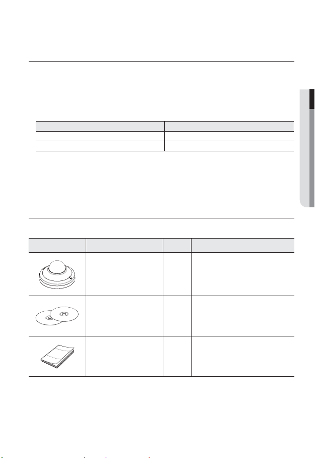
WHAT’S INCLUDED
Please check if your camera and accessories are all included in the product package.
Appearance Item Name Quantity Description
Camera 1
Instruction book,
Installer S/W CD,
CMS S/W DVD
2
● OVERVIEW
Quick Guide
(Optional)
1
English _11
Page 12
overview
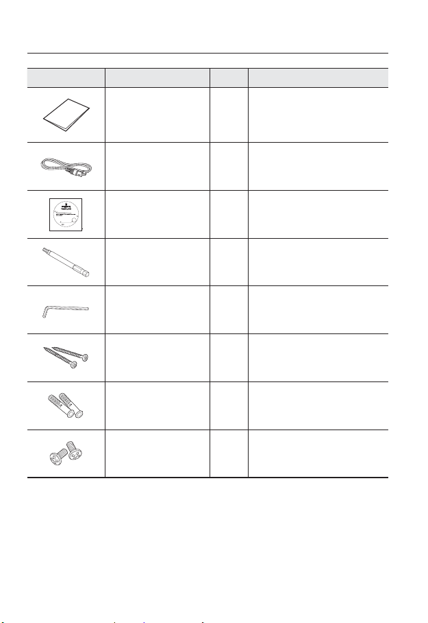
Appearance Item Name Quantity Description
Warranty card
(Optional)
Cable for the testing monitor 1
5.5 mm 2 Holes
20 mm CABLE Hole
케이블 구멍
Template 1 Product installation guide
Drill bit 1
L Wrench 1
Tapping Screw 2
1
Used to test the camera connection to a
portable display device
For dome cover disassembly, assembly or
camera installation.
For dome cover disassembly, assembly or
camera installation.
Used for installation on the
wall or ceiling
For fixing a screw,
Plastic Anchor 2
Inserted in a hole
(reinforced anchoring force)
Used for assembling the dome case when
Machine Screws 2
installing the product on the pipe, wall
mount, etc. or blocking a hole.
12_ overview
Page 13
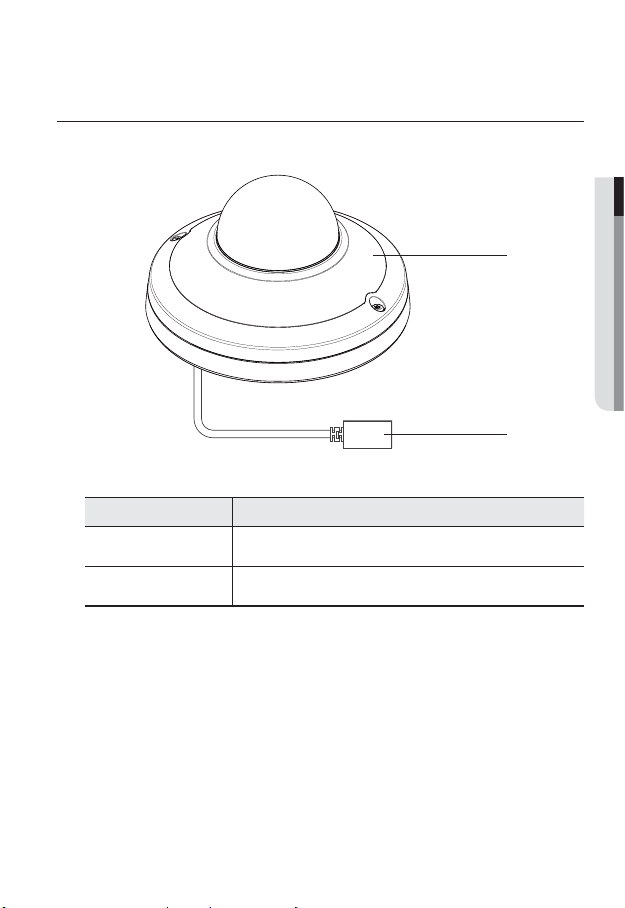
AT A GLANCE
Appearance
Item Description
Dome cover
● OVERVIEW
b
Case cover used to protect the lens and the main unit.
b
PoE Connector
Connects to the network and supplies power through Ethernet cable.
English _13
Page 14
overview
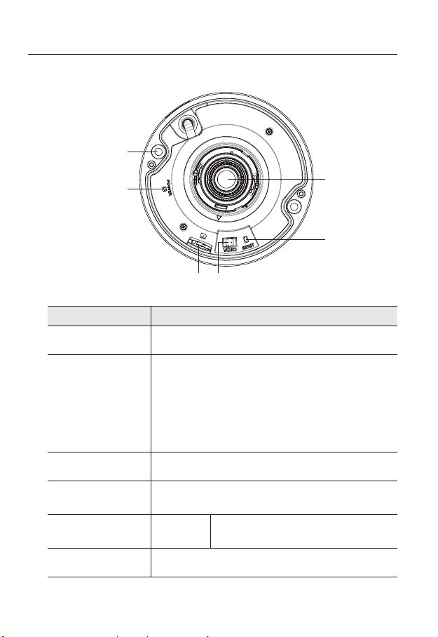
Inside
c
Item Description
Lens Lens for the camera.
The button restores all camera settings to the factory default.
Press and hold for about 5 seconds to reboot the system.
If you reset the camera, the network settings will be adjusted so that
Reset Button
b
Video Out Port Analog video output port. (for installation)
c
Micro SD Memory
Card Compartment
Power indicators POWER
Camera fixing hole Hole used for securing the camera onto a ceiling.
J
DHCP can be enabled. If there is no DHCP server in the network, you
must run the IP Installer program to change the basic network settings
such as IP address, Subnet mask, Gateway, etc., before you can
connect to the network.
Compartment for the Micro SD memory card.
ON : While the power is on
OFF : If the power is off
b
14_ overview
Page 15
installation & connection
INSTALLATION
This camera is waterproof and in compliance with the IP66 spec, but the jack connected to the
J
external cable is not. You are recommended to install this product below the edge of eaves to
prevent the cable from being externally exposed.
Precautions before installation
Ensure you read out the following instructions before installing the camera:
• Select an installation site that can hold at least 5 times the camera’s weight.
• Stuck-in or peeled-off cables can cause damage to the product or a fire.
• For safety purposes, keep anyone else away from the installation site.
And put aside personal belongings from the site, just in case.
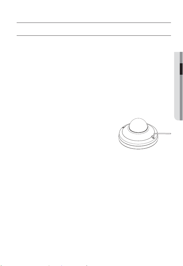
Disassembling
1. Using the L-wrench or drill bit provided, loosen
2 screws by turning them counterclockwise and
separate the dome cover.
Note that it is not necessary to loosen the screws completely.
● INSTALLATION & CONNECTION
English _15
Page 16
installation & connection
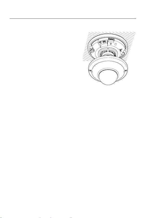
Installation
1. Using the template provided as an
accessory, drill a hole(diameter 6mm, min
depth of 45mm) for screw installation and
firmly insert the plastic anchor provided as
an accessory.
2. Fit the bottom hole to the anchor hole and
insert and fix the taping screw (M4xL40).
3. Connect and arrange the necessary cables
lest that they should be damaged or twisted
while installing the camera.
Adjust the lens in a desired direction by
4.
referring to the “Adjusting the monitoring
direction for the camera” section. (page 17)
5. Close the dome cover.
To ensure waterproofing, tight up the fixing bolts using the L-wrench and drill bit.
16_ installation & connection
Page 17

Adjusting the monitoring direction for the camera
Pan
Tilt
Lens rotation
Adjusting the monitoring direction
You can adjust the camera direction only when the camera is fixed on the ceiling.
Where, rotating the camera unit to the left or right is called Pan, adjusting the tilt is called
Tilt, and turning the lens on its axis is called Rotation.
- The effective range of pan is a total of 355 degrees.
- The effective range of rotation is a total of 355 degrees.
- The effective range of tilt is a total of 59 degrees.
Methods of adjustment
1. After installing the camera, adjust the panning angle in consideration of the
monitoring direction.
2. Set the horizontal angle so that the image is not reversed.
3. Adjust the tilt angle so that the camera faces toward the monitoring object.
● INSTALLATION & CONNECTION
English _17
Page 18

installation & connection
Outdoor installation
When you install the camera outdoors, it should be waterproofed with waterproof butyl
rubber tape (which can be purchased in stores) so that water does not leak from the gap of
the cable connected in the outdoor area.
1. Connect the PoE cable.
2. Wrap the black cable jacket (Area A) and the
cable connection area with waterproof (butyl
rubber) tape so that more than half of the butyl rubber tape is overlapped.
If the cable jacket is not waterproofed properly, then it can directly cause leakage. Make sure to
J
protect the cable with a dense layer of taping.
Waterproof butyl tape is made of butyl rubber that can be stretched to twice its normal length.
Camera System
AA
18_ installation & connection
Page 19
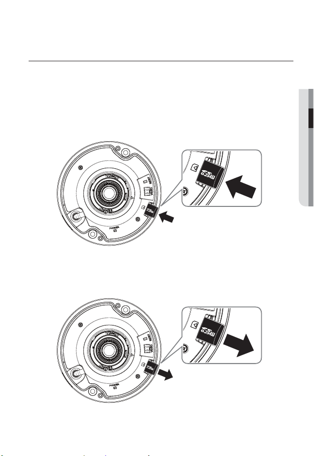
INSERTING/REMOVING A MICRO SD MEMORY CARD
Disconnect the power cable from the camera before inserting the Micro SD memory card.
J
Do not insert the Micro SD memory card while it’s upside down by force.
Otherwise, it may damage the Micro SD memory card.
Inserting a Micro SD Memory Card
Push the Micro SD memory card in the direction of the arrow shown in the diagram.
Removing a Micro SD Memory Card
Gently press down on the exposed end of the memory card as shown in the diagram to
eject the memory card from the slot.
● INSTALLATION & CONNECTION
English _19
Page 20

installation & connection
Pressing too hard on the Micro SD memory card can cause the card to shoot out uncontrollably
J
from the slot when released.
Before removing your Micro SD memory card, turn off the camera or go to <Storage>, turn the
device off, and press the [Apply (
If you turn off the camera or remove the Micro SD memory card that contains data from the
product, the data may be lost or damaged.
MEMORY CARD INFORMATION (NOT INCLUDED)
What is a memory card?
The memory card is an external data storage device that has been developed to offer an
entirely new way to record and share video, audio, and text data using digital devices.
Selecting a memory card that’s suitable for you
Your camera supports Micro SD/SDHC/SDXC memory cards.
You may, however, experience compatibility issues depending on the model and make of
the memory card.
For your camera, we recommend you use a memory card from the following
manufacturers:
Micro SD/SDHC/SDXC Memory Card : Sandisk, Transcend
Memory cards of 4GB ~ 64GB is recommended for using with this camera.
Playback performance can be affected depending on the speed of memory card, so use
the high-speed memory card.
For the framerate below 30 fps, it is recommended to use the specification memory card of
Class 6 or higher.
For the framerate over 31 fps, it is recommended to use the specification memory card of
Class 10 UHS or higher.
)] button. (Page 80)
Memory Card Components
Contacts
Micro SD/SDHC/SDXC
20_ installation & connection
Page 21
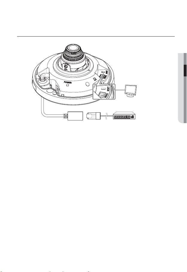
CONNECTING WITH OTHER DEVICE
Powering and networking
Connect the PoE device and camera’s PoE connectors.
Connect to a PoE (Power over Ethernet) enabled router’s PoE connector.
J
Use PoE (Power over Ethernet) that is compliant with the IEEE802.3af protocols.
● INSTALLATION & CONNECTION
Monitor
PoE device
English _21
Page 22
network connection and setup
You can set up the network settings according to your network configurations.
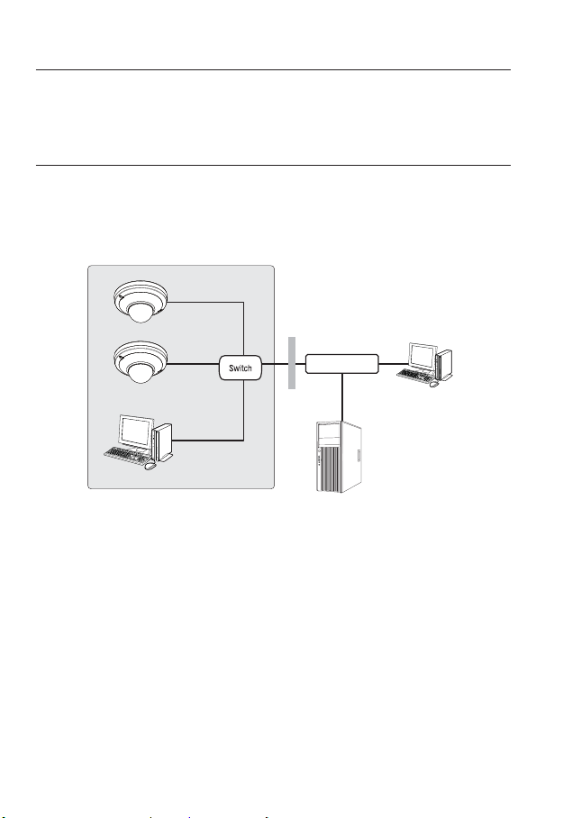
CONNECTING THE CAMERA DIRECTLY TO LOCAL AREA
NETWORKING
Connecting to the camera from a local PC in the LAN
1. Launch an Internet browser on the local PC.
2. Enter the IP address of the camera in the address bar of the browser.
Camera
INTERNET
Camera
Local PC
<Local Network>
A remote PC in an external Internet out of the LAN network may not be able to connect to the
M
camera installed in the intranet if the port-forwarding is not properly set or a firewall is set.
In this case, to resolve the problem, contact your network administrator.
By factory default, the IP address will be assigned from the DHCP server automatically.
If there is no DHCP server available, the IP address will be set to 192.168.1.100.
To change the IP address, use the IP Installer.
For further details on IP Installer use, refer to “Static IP Setup”. (Page
Firewall
External Remote PC
DDNS Server
(Data Center, KOREA)
27)
22_ network connection and setup
Page 23

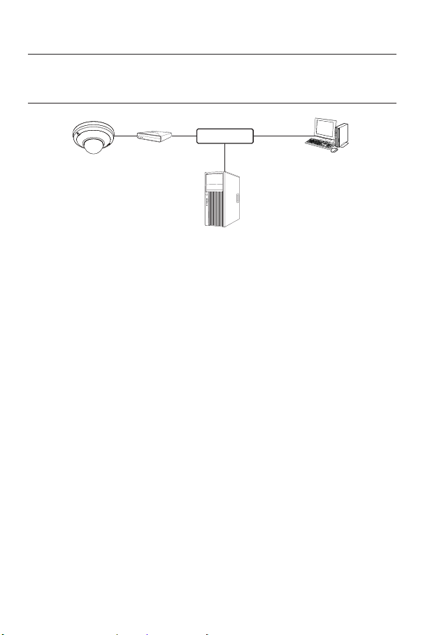
CONNECTING THE CAMERA DIRECTLY TO A DHCP
BASED DSL/CABLE MODEM
Camera External Remote PC
1. Connect the user PC directly with the network camera.
2. Run the IP Installer and change the IP address of the camera so that you can use
the web browser on your desktop to connect to the Internet.
3. Use the Internet browser to connect to the web viewer.
4. Move to [Setup] page.
5. Move to [Network] – [DDNS] and configure the DDNS settings.
6. Move to [Network] – [Interface], and set the network type to [DHCP].
7. Connect the camera, which was removed from your PC, directly to the modem.
8. Restart the camera.
For registering the DDNS settings, refer to “Registering with DDNS”. (page 71)
M
For configuring the DDNS settings, refer to “DDNS”. (page 70)
For setting the network type, refer to “Interface”. (page 68)
DSL/Cable Modem
INTERNET
DDNS Server
(Data Center, KOREA)
●
NETWORK CONNECTION AND SETUP
English _23
Page 24
network connection and setup
CONNECTING THE CAMERA DIRECTLY TO A PPPoE
MODEM
Camera External Remote PC
1. Connect the user PC directly with the network camera.
2. Run the IP Installer and change the IP address of the camera so that you can use
the web browser on your desktop to connect to the Internet.
3. Use the Internet browser to connect to the web viewer.
4. Move to [Setup] page.
5. Move to [Network] – [DDNS] and configure the DDNS settings.
6. Move to [Network] - [Interface] Setup Page, set the network type to [PPPoE], and
enter the ID and password.
7. Connect the camera, which was removed from your PC, directly to the modem.
8. Restart the camera.
For registering the DDNS settings, refer to “Registering with DDNS”. (page 71)
M
For configuring the DDNS settings, refer to “DDNS”. (page 70)
For setting the network type, refer to “Interface”. (page 68)
PPPoE Modem
INTERNET
DDNS Server
(Data Center, KOREA)
24_ network connection and setup
Page 25
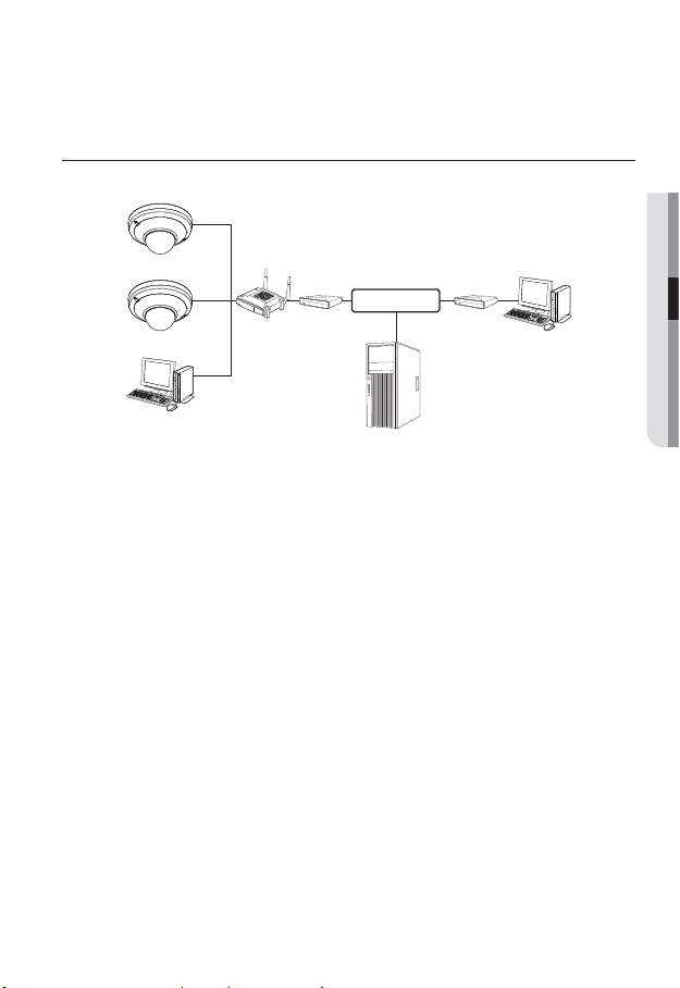
CONNECTING THE CAMERA TO A BROADBAND ROUTER
WITH THE PPPoE/CABLE MODEM
This is for a small network environment such as homes, SOHO and ordinary shops.
Camera
●
NETWORK CONNECTION AND SETUP
INTERNET
PPPoE or
Cable Modem
DDNS Server
(Data Center, KOREA)
External Remote PC
Camera
Local PC
Broadband
Router
PPPoE or
Cable Modem
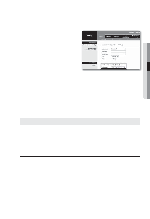
Configuring the network settings of the local PC connected to a
Broadband Router
Configuring the network settings of the local PC connected to a Broadband Router, follow
the instructions below.
• Select : <Network> <Properties> <Local Area Connection> <General>
<Properties> <Internet Protocol (TCP/IP)> <Properties> <Obtain an
IP address automatically> or <Use the following IP address>.
• Follow the instructions below if you select <Use the following IP address>:
ex1) If the address (LAN IP) of the Broadband Router is 192.168.1.1
IP address : 192.168.1.100
Subnet Mask : 255.255.255.0
Default Gateway : 192.168.1.1
ex2) If the address (LAN IP) of the Broadband Router is 192.168.0.1
IP address : 192.168.0.100
Subnet Mask : 255.255.255.0
Default Gateway : 192.168.0.1
ex3) If the address (LAN IP) of the Broadband Router is 192.168.xxx.1
IP address : 192.168.xxx.100
Subnet Mask : 255.255.255.0
Default Gateway : 192.168.xxx.1
For the address of the Broadband Router, refer to the product’s documentation.
M
For more information about port forwarding of the broadband router, refer to “Port Range
Forward (Port Mapping) Setup”. (Page
32)
English _25
Page 26
network connection and setup
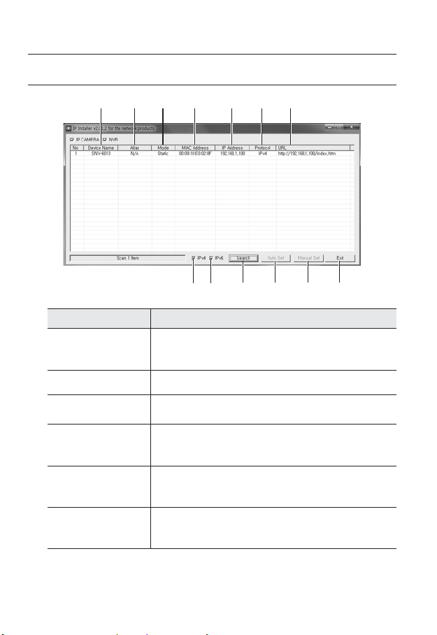
BUTTONS USED IN IP INSTALLER
b c
Item Description
Device Name
Alias This function is not currently implemented.
b
Mode
c
MAC(Ethernet)
Address
IP Address
Protocol
26_ network connection and setup
Model name of the connected camera.
Click the column to sort the list by model name.
However, search will be stopped if clicked during the search.
Displays either <Static>, <Dynamic> or <PPPoE> for the current network
connection status.
Ethernet address for the connected camera.
Click the column to sort the list by Ethernet address.
However, search will be stopped if clicked during the search.
IP address.
Click the column to sort the list by IP address.
However, search will be stopped if clicked during the search.
Network setting for the camera.
The factory default is “IPv4”.
Cameras with the IPv6 setting will be displayed “IPv6”.
m
Page 27
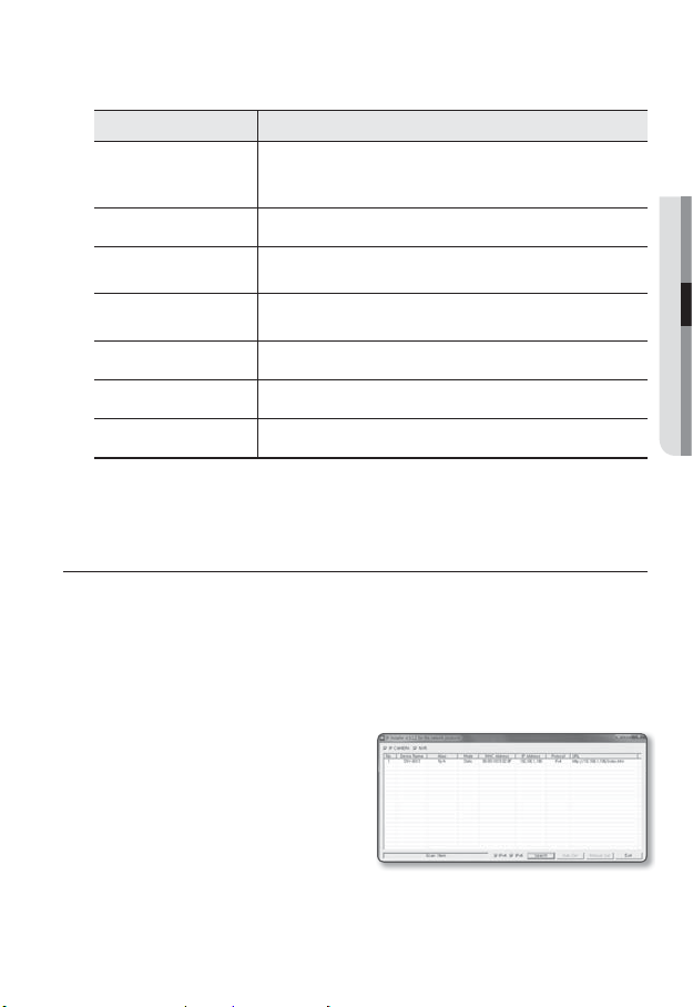
Item Description
URL
IPv4 Scans for cameras with the IPv4 setting.
IPv6
Search
Auto Set The IP Installer automatically configures the network settings.
Manual Set You should configure the network settings manually.
Exit Exits the IP Installer program.
m
For the IP installer, use only the installer version provided in the installation CD or use the latest one if
M
available. You can download the latest version from the Samsung web site (www.samsungcctv.com).
DDNS URL address enabling access from the external Internet.
However, this will be replaced with the <IP Address> of the camera if
DDNS registration has failed.
Scans for cameras with the IPv6 setting.
Activated in an IPv6 compliant environment only.
Scans for cameras that are currently connected to the network.
However, this button will be grayed out if neither IPv4 nor IPv6 is checked.
STATIC IP SETUP
Manual Network Setup
Run <IP Installer_v2.XX.exe> to display the camera search list.
At the initial startup, both [Auto Set] and [Manual Set] will be grayed out.
For cameras found with the IPv6 setting, these buttons will be grayed out as the cameras do not
M
support this function.
1. Select a camera in the search list.
Check the MAC address of the camera
on the camera’s label.
Both the [Auto Set] and [Manual Set]
buttons will be activated.
●
NETWORK CONNECTION AND SETUP
English _27
Page 28
network connection and setup
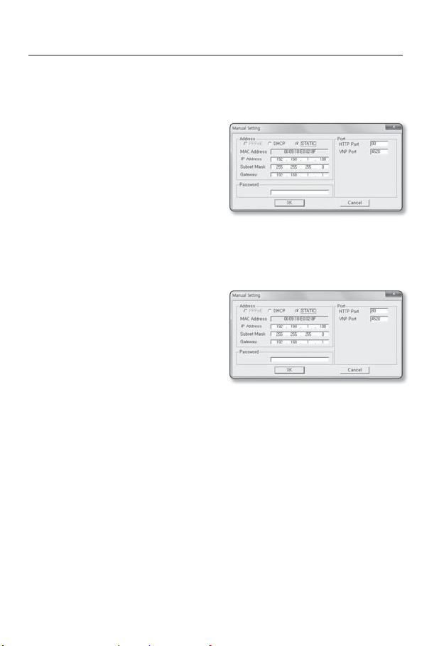
2. Click [Manual Set].
The Manual Setting dialog appears.
<IP Address>, <Subnet Mask>, <Gateway>, <HTTP Port>, and <VNP Port> of
the camera are displayed in the preset values.
3. In the <Address> pane, provide the
necessary information.
• MAC (Ethernet) Address : The MAC
address imprinted on the camera
label is automatically displayed and
requires no user setting.
IP related parameters can be set only
M
when DHCP is not checked.
If not using a Broadband Router
For setting <IP Address>, <Subnet Mask>, and <Gateway>, contact your network
administrator.
4. In the <Port> pane, provide necessary
information.
• HTTP Port : Used to access the
camera using the Internet browser,
defaulted to 80.
• VNP Port : Used to control the video
signal transfer, defaulted to 4520.
5. Enter the password.
Enter the password of “admin” account, which was used to access the camera.
The default password is “4321”.
The default password is vulnerable to security threats. You should change it.
J
If you want to change the password, refer to “Administrator password change” of the user
setup. (page
100)
6. Click [OK].
Manual network setup will be completed.
28_ network connection and setup
Page 29
If using a Broadband Router
• IP Address : Enter an address falling in
the IP range provided by the Broadband
Router.
ex) 192.168.1.2~254,
192.168.0.2~254,
192.168.XXX.2~254
• Subnet Mask : The <Subnet Mask>
of the Broadband Router will be the
<Subnet Mask> of the camera.
• Gateway : The <Local IP Address> of
the Broadband Router will be the <Gateway> of the camera.
The settings may differ depending on the connected Broadband Router model.
M
For more information, refer to the user manual of the applicable router.
For more information about port forwarding of the broadband router, refer to “Port Range
Forward (Port Mapping) Setup”. (Page
If the Broadband Router has more than one camera connected
Configure the IP related settings and the Port related settings distinctly with each other.
ex)
Category Camera #1 Camera #2
32)
●
NETWORK CONNECTION AND SETUP
IP related settings
Port related settings
If the <HTTP Port> is set other than 80, you must provide the <Port> number in the address bar
M
of the Internet browser before you can access the camera.
ex) http://IP address : HTTP Port
IP Address
Subnet Mask
Gateway
HTTP Port
VNP Port
http://192.168.1.100:8080
192.168.1.100
255.255.255.0
192.168.1.1
8080
4520
192.168.1.101
255.255.255.0
192.168.1.1
8081
4521
English _29
Page 30
network connection and setup
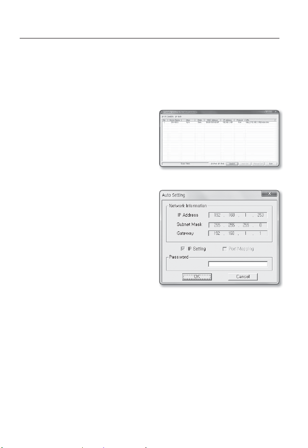
Auto Network Setup
Run <IP Installer_v2.XX.exe> to display the camera search list.
At the initial startup, both [Auto Set] and [Manual Set] will be grayed out.
For cameras found with the IPv6 setting, these buttons will be grayed out as the cameras do not
M
support this function.
1. Select a camera in the search list.
Check the MAC address of the camera
on the camera’s label.
Both the [Auto Set] and [Manual Set]
buttons will be activated.
2. Click [Auto Set].
The Auto Setting dialog appears.
The <IP Address>, <Subnet Mask>,
and <Gateway> will be set automatically.
3. Enter the password.
Enter the password of “admin” account,
which was used to access the camera.
The default password is “4321”.
The default password is vulnerable to
J
security threats. You should change it.
If you want to change the password, refer
to “Administrator password change” of
the user setup. (page
4. Click [OK].
Auto network setup will be completed.
100)
30_ network connection and setup
Page 31

DYNAMIC IP SETUP
Dynamic IP Environment Setup
• Example of the Dynamic IP environment
- If a Broadband Router, with cameras connected, is assigned an IP address by the
DHCP server
- If connecting the camera directly to modem using the DHCP protocols
- If IPs are assigned by the internal DHCP server via the LAN
Checking the Dynamic IP
1. Run the IP Installer on the user’s local
computer.
Cameras allocated with <Dynamic IP>
address are shown in the list.
2. Select a camera from the search result.
3. Click the [Manual Set] button and
check the camera’s <Dynamic IP>
address.
If you uncheck <DHCP>, you can
change IP to <Static>.
●
NETWORK CONNECTION AND SETUP
English _31
Page 32
network connection and setup
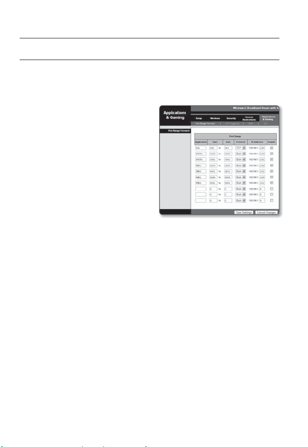
PORT RANGE FORWARD (PORT MAPPING) SETUP
If you have installed a Broadband Router with a camera connected, you must set the port range
forwarding on the Broadband Router so that a remote PC can access the camera in it.
Manual Port Range Forwarding
1. From the Setup menu of the Broadband
Router, select <Applications &
Gaming> - <Port Range Forward>.
For setting the port range forward for
a third-party Broadband Router, refer
to the user guide of that Broadband
Router.
2. Select <TCP> and <UDP Port>
for each connected camera to the
Broadband Router.
Each port number for the Broadband
Router should match that specified in
<Setup> - <Network> - <Port> from
the camera’s web viewer menu.
3. When done, click [Save Settings].
Your settings will be saved.
Above sample instructions are based on the CISCO’s Broadband Router.
M
The settings may differ depending on the connected Broadband Router model.
For more information, refer to the user manual of the applicable router.
32_ network connection and setup
Page 33
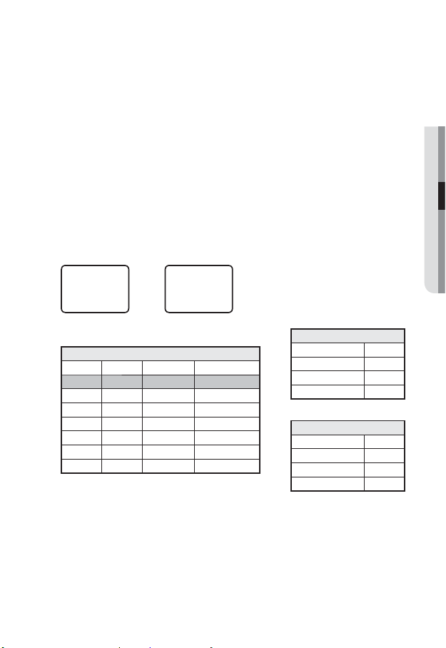
Setting up Port Range Forward for several network cameras
When several network cameras are connected to one Broadband Router device, you
should forward the TCP 943 port of the router to the TCP 943 port of a connected camera.
If you don’t set properly the TCP 943 port of the router, you cannot get any video stream from the
J
web page of the camera.
• TCP 943 port is a port for the Silverlight policy server of a camera.
• You can set a rule of Port Forwarding on the Broadband Router device through its
configuration web page.
• You cannot change the Silverlight policy server port of a camera.
• You can change the ports of the camera except the policy server port through its
configuration web pages.
When Camera1 and Camera2 are connected to a router :
●
NETWORK CONNECTION AND SETUP
User Internet
Start End Protocol IP Address
943 943 TCP 192.168.1.100
3000 3000 TCP/UDP 192.168.1.100
3001 3001 TCP/UDP 192.168.1.101
4520 4520 TCP/UDP 192.168.1.100
4521 4521 TCP/UDP 192.168.1.101
8080 8080 TCP/UDP 192.168.1.100
8081 8081 TCP/UDP 192.168.1.101
M
Ù
Ú
Broadband Router
Port forwarding can be done without additional router setup if the router supports the UPnP
(Universal Plug and Play) function.
After connecting the network camera, set <Quick connect> of <Samsung DDNS> to <On> in
the “Setup Network DDNS” menu.
Camera1 (192.168.1.100)
HTTP Port 8080
Ù
Ù
Device port 4520
RTSP Port 3000
Policy Server Port 943
Camera2 (192.168.1.101)
HTTP Port 8081
Device port 4521
RTSP Port 3001
Policy Server Port 943
English _33
Page 34

network connection and setup
CONNECTING TO THE CAMERA FROM A SHARED LOCAL PC
1. Run the IP Installer.
It will scan for connected cameras and
display them as a list.
2. Double-click a camera to access.
The Internet browser starts and
connects to the camera.
Access to the camera can also be gained by typing the camera’s IP address in the address bar of
M
the Internet browser.
CONNECTING TO THE CAMERA FROM A REMOTE PC VIA
THE INTERNET
Since using the IP Installer on a remote computer that is not in the Broadband Router’s network
cluster is not allowed, users can access cameras within a Broadband Router’s network by using
the camera’s DDNS URL.
1. Before you can access a camera in the Broadband Router network, you should have
set the port range forward for the Broadband Router.
2. From the remote PC, launch the Internet browser and type the DDNS URL address
of the camera, or the IP address of the Broadband Router in the address bar.
ex) http://www.samsungipolis.com/Product ID
For registering the DDNS settings, refer to “Registering with DDNS”. (page 71)
M
34_ network connection and setup
Page 35
web viewer
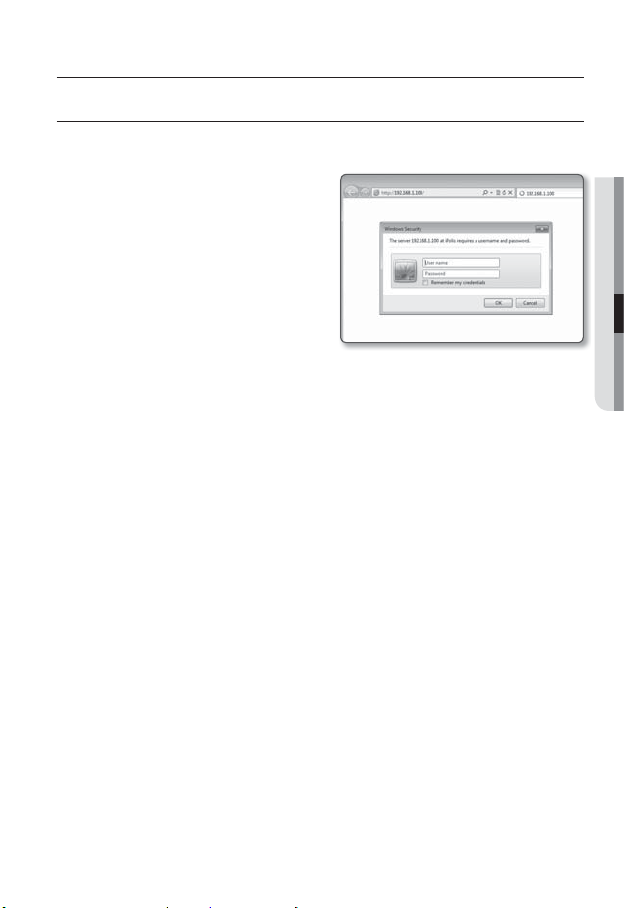
CONNECTING TO THE CAMERA
Normally, you would
1. Launch the Internet browser.
2. Type the IP address of the camera in
the address bar.
ex) • IP address (IPv4) : 192.168.1.100
http://192.168.1.100
- the Login dialog should appear.
IP address (IPv6) : 2001:230:abcd:
•
ffff:0000:0000:ffff:1111
http://[2001:230:abcd:ffff:0000
:0000:ffff:1111] - the Login dialog
should appear.
If the HTTP port is other than 80
1. Launch the Internet browser.
2. Type the IP address and HTTP port number of the camera in the address bar.
ex) IP address : 192.168.1.100:HTTP Port number(8080)
http://192.168.1.100:8080 - the Login dialog should appear.
Using URL
1. Launch the Internet browser.
2. Type the DDNS URL of the camera in the address bar.
ex) URL address : http://www.samsungipolis.com/Product ID
- the Login dialog should appear.
Network connection is disabled in the LAN only environment.
J
● WEB VIEWER
English _35
Page 36

web viewer
Connecting via UPnP
1. Run the client or operating system in support of the UPnP protocol.
2. Click the camera name for search.
In the Windows operating system, click the camera name searched from the
network menu.
- The login window is displayed.
Connecting via Bonjour
1. Run the client or operating system in support of the Bonjour protocol.
2. Click the camera name for search.
In the Mac operating system, click the camera name searched from the Bonjour tab
of Safari.
- The login window is displayed.
To check the DDNS address
If the camera is connected directly to the DHCP cable modem, DSL modem, or PPPoE
modem, the IP address of your network will be changed each time you try to connect to
the ISP (Internet Service Provider) server.
If this is the case, you will not be informed of the IP address changed by DDNS.
Once you register a dynamic IP-based device with the DDNS server, you can easily check
the changed IP when you try to access the device.
To register your device to the <DDNS> server, visit www.samsungipolis.com and register
your device first, and then set the Web Viewer’s <Network> - <DDNS> to <Samsung
DDNS>, as well as providing <Product ID> that had been used for DDNS registration.
36_ web viewer
Page 37
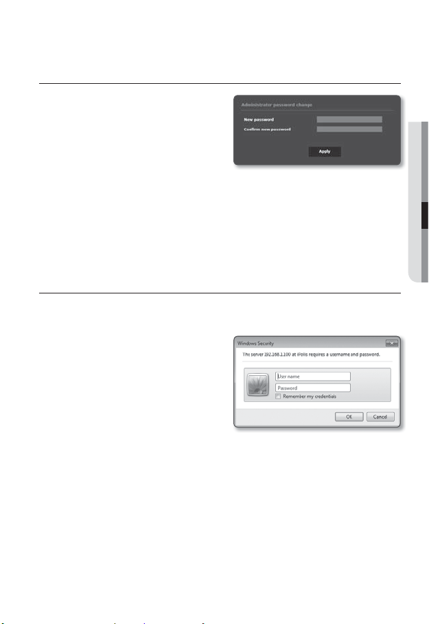
PASSWORD SETTING
When you access the product for the first time,
you must register the login password.
When the “Password change” window appears,
enter the new password.
A new password should be eight to fifteen
J
letters long and a combination of at least
two of uppercase/lowercase alphabets, numbers and special characters.
Special characters that are allowed. : ~`!@#$%^*()_-+=|{}[].?/
-
You cannot use your ID as your password. You cannot repeat same letters more than twice and
you cannot use the three consecutive keyboard buttons.
If you lose your password, you cannot use the equipment. You must memorize the password or
write it down somewhere.
LOGIN
Whenever you access the camera, the login window appears.
Enter the User ID and password to access the camera.
1. Enter “admin” in the <User name>
input box.
The administrator ID, “admin”, is fixed
and can not be changed.
2. Enter the password in the <Password>
input field.
3. Click [OK].
If you have logged in successfully, you
will the Live Viewer screen.
If you check the “Remember my credentials” option when your input is done, in future you will
M
be logged in automatically without being prompted to enter the login information.
You will experience the best video quality if the screen size is 100%. Reducing the ratio may cut
the image on the borders.
● WEB VIEWER
English _37
Page 38
web viewer
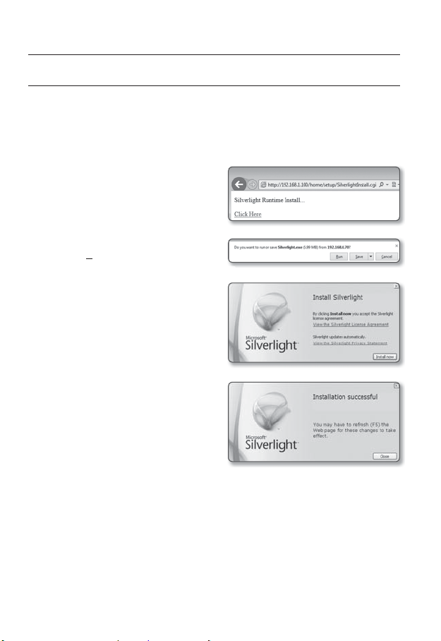
INSTALLING SILVERLIGHT RUNTIME
If your PC has not installed Silverlight Runtime or has just installed an old runtime version, you will
be redirected to the Silverlight Runtime installation page automatically when accessing the web
viewer.
To install on Windows OS
1. Click <Click Here>.
2. When the file download dialog pops up,
click <Run>.
3. When the download is completed, click <Yes>.
4. The Silverlight Runtime installation page
will be displayed. <Install now> to
proceed with the installation.
5. When done, click <Close>.
38_ web viewer
Page 39
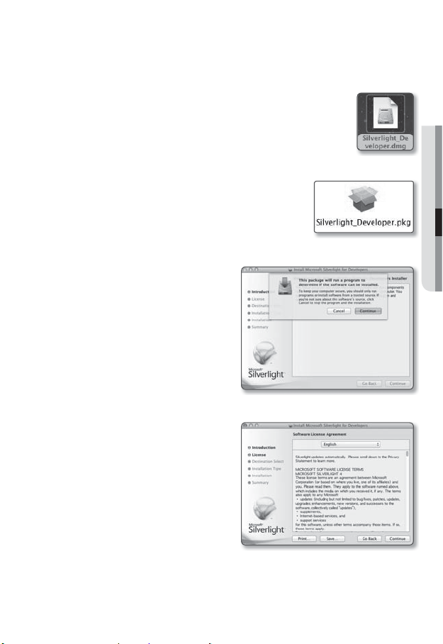
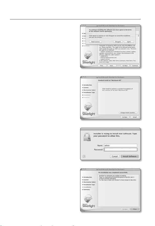
To install on MAC OS
1. Run the file trailing with “.dmg”.
2. Run the install package file automatically created, ending
with “.pkg”.
3. Click <Continue>.
4. Select your language on the language
selection screen, and click <Continue>.
● WEB VIEWER
English _39
Page 40
web viewer
5. Click <Agree>.
6. Click <Install>.
7. Enter the password of the account
currently logged in, and click <Install
Software> and continue.
8. Once completed, click <Close>.
40_ web viewer
Page 41
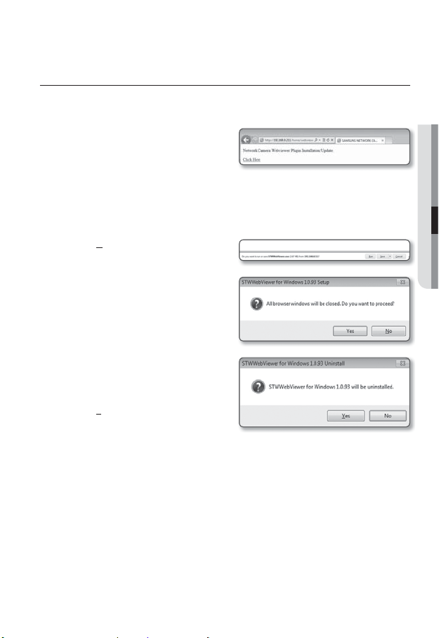
INSTALLING STW WebViewer PLUGIN
If connecting to a camera for the first time, you will see the installation message. Then, install the
required WebViewer Plugin to access the camera and control the video from it in real time.
1. When the monitoring page is accessed
for the very first time, the installation
page is displayed. Click [Click Here] to
begin installation.
If the plug-in installation file download status is suspended at 99% in the Internet Explorer
J
browser, retry it after selecting “Release SmartScreen filter” in “Tool SmartScreen filter”.
2. Click [Run] in the message window.
3. Click [Yes] when the notice window
saying that all browser windows will be
closed.
4. When the old version of the Web Viewer
Plug-in is installed, a notice window
saying the old version will be deleted is
displayed.
Click [Yes ] when the notice window is
displayed.
Steps 4 and 5 will be skipped if no Web Viewer Plug-in is installed.
M
● WEB VIEWER
English _41
Page 42

web viewer
5. Click [OK].
The old version of Web Viewer Plug-in
is deleted.
6. Click [Install] to begin installation of the
Web Viewer Plug-in.
7. Click [Finish].
STW Web Viewer Plug-in installation is
completed.
In your internet explorer, if you need
J
to move to the installation screen
after installing the STW webviewer
plugin, check whether webviewer_
activexplugin_lib.control in the “Tool
Additional Function Management” menu
is “Activated”. If not, and if there is a
persisting problem, then select “Tools
Internet Options General” and delete all the search records.
42_ web viewer
Page 43

USING THE LIVE SCREEN
b
Item Description
Monitoring Move to the monitoring screen.
Playback
b
Setup Move to the Setup screen.
c
Viewer Screen
Profile type
Screen
Optimization
Fix the resolution
Move to the screen where you can search for the video recording saved in your Micro
SD memory card or NAS.
Displays the Live video on the screen.
You can select a profile type in <Video profile> under the <Video> setup menu.
The video size of the camera will switch to as big as the Web browser.
Regardless of the resolution setup configured in the camera, it sets the resolution to
640x480. Press it again to switch back to the default resolution.
c
You can use the mouse wheel to activate the digital zooming in Viewer screen.
When the Web Viewer is connected, the profile information currently using is
displayed.
● WEB VIEWER
English _43
Page 44

web viewer
Item Description
Full Screen Switch the current video to the maximum size of the monitor.
Capture Saves the snapshot as an image file in the .bmp or .jpg format.
Hide the context
menu
To capture the snapshot
1. Click [Capture ( )] on the scene to
capture.
The Capture dialog should appear.
2. Confirm the save path and click [Save]
button.
The screenshot will be saved in the
specified path.
If you encounter an interrupted video
M
when capturing the image with IE8 on a Windows 7-based PC, deselect “Turn On Protected
Mode” from “Tools – Internet Options – Security”.
If the screen is not captured by IE browser in Windows 7 or 8, run the IE Browser with the Admin
privilege.
To fit the full screen
1. Click the [Full Screen (
2. This will fit the Viewer to the full screen.
3. To exit the full screen mode, press [Esc] on the keyboard.
The left-corner context menu will disappear but only the menu icon.
)] button.
For the Internet Explorer and Google Chrome browser, you can switch to the full screen.
M
44_ web viewer
Page 45

PLAYING THE RECORDED VIDEO
Before you can play the video, you must configure the record settings. For details on record settings,
M
refer to “Storage”. (page
Name of event search screen and its function
b
c
Item Description
Search range setting
Search event setting Set the event type to search within the search period.
b
80)
Set the search date and time range for data saved in your Micro SD memory
card or NAS.
● WEB VIEWER
Event search Run the event search.
c
English _45
Page 46

web viewer
To play the content after searching by event
1. Click the [Playback ( )] button.
2. Specify the start time and end time of
your search.
3. Select an event type for your search
within the specified period.
4. Click the [Event search] button.
The search results will be displayed in
the list.
If more than 800 events are recorded
M
within the search period, your search will be limited up to the date when the 800th event is
recorded.
For instance, if the search period is between 10th and 15th day of the month, and more than 800
events were recorded 10th through 11th, your search will be limited up to 11th day with a total of
800 events, and events after then (from 12th) will not be found.
5. Select a data item to play in the search
list.
6. Click the [Play (
7. To stop playing the video, click
[Stop (
8. To return to the search screen,
click [Exit (
)] button.
)].
)].
46_ web viewer
Page 47

Name of time search screen and its function
b
c
Item Description
Time bar The section in the specific period is played by moving the time bar.
Search date setting
b
Screen optimization The camera image is converted to fit the Web browser window.
c
Fix the resolution
Full screen The current image is converted to cover the maximum size of the monitor.
Set the search date using the calendar.
If there is data saved in your Micro SD memory card or NAS on the
day, it is marked as a box on the calendar.
Regardless of the resolution setup configured in the camera, it sets
the resolution to 800x600. Press it again to switch back to the default
resolution.
● WEB VIEWER
Capture The current image is saved as a .jpg or .bmp image file.
English _47
Page 48
web viewer
Item Description
Video information Time data of the replayed video is displayed on the screen.
Set the desired date to make a backup copy of video data saved in your
Backup
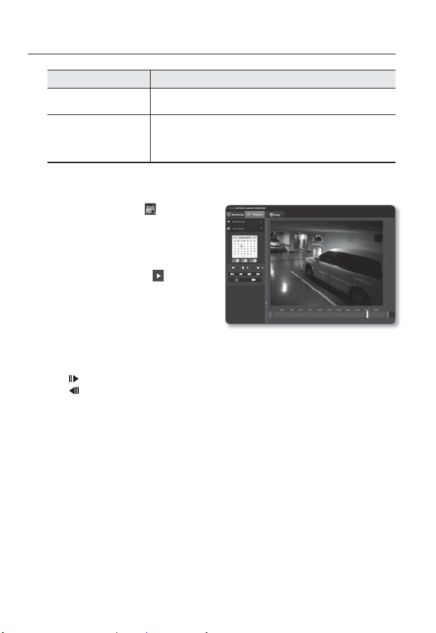
To play after searching by time
1. Click [Time Search ( )].
2. Click a desired date in the calendar.
The video on the specified date will be
played.
3. If the video playback is stopped, select
a time and click [Play (
The video on the selected time will be
played.
4. While the video is being played, the
recording time for the current video will
be shown.
5. Search for the video forward or backward, and control the play speed.
- How to Control the Play Interval
: Select this button to move 1 frame forward.
: Select this button to move 1 second back.
- To control the play speed
If selecting ), the button will switch to x1, x2, x4, x8, and the play speed will
increase accordingly.
When the ( button is selected, the playing speed is decreased to -1x, -2x, -4x, -8x
and the playing speed slows down gradually. Subsequently the quick playing speed
is returned to the normal speed and the reverse playing speed increases.
- To control the playback direction
If you see the ) button with the play speed displayed, the video will be played
forward; Whereas, if you see the ( button with the play speed displayed, the video
will be played backward.
Micro SD memory card or NAS.
Can be set as up to 5 minutes.
)].
48_ web viewer
Page 49
- How to set the time bar
If you press the
If you press the
can be selected more easily.
6. Move [Time bar (
The time containing a normal recoding file will be highlighted in blue; the time with
the event recording will be highlighted in red.
button, the details of the time bar section can be viewed.
button, you can view a wider range of times and the desired time
)] to a desired time point of the video before playing it.
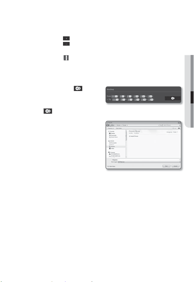
To back up the searched video
1. During playback, click [ ] on the
scene to back up.
The scheduling window for backup
start and end time appears.
2. Click [ ] button.
The Save As window appears.
3. Confirm the save path and click [Save]
button.
The screenshot will be backed up to
the specified path.
To play the backup video
The backed up images are saved in an .avi format. Gom Player, VLC Player, and Window
Media Player are recommended as the media player compatible with this format.
In case of Windows Media Player, download the latest codec from www.windows7codecs.com
M
and install it prior to use.
● WEB VIEWER
English _49
Page 50
web viewer
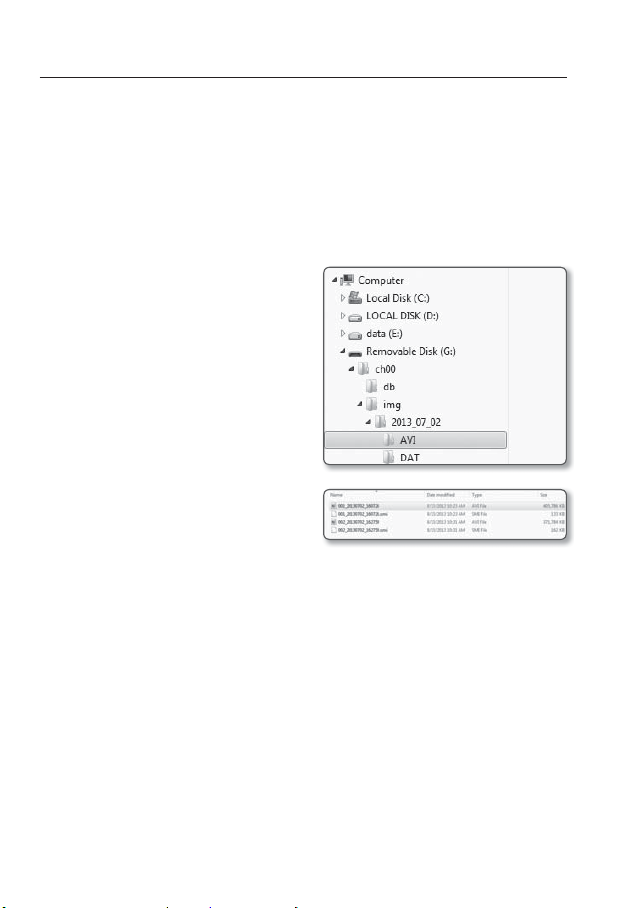
To Play an AVI File
(1) Micro SD memory card
1. Separate the micro SD memory card from the camera.
Before separating the micro SD memory card, set the <Device> to <Off> in the “Setup
J
Event Storage” menu.
2. Insert the micro SD memory card into the PC.
3. Play the AVI file in the “\ch00\img\
YYYY_mm_DD\AVI” directory, using a
media player.
A filename starts with the format “001_
M
YYYYMMDD_HHMMSS.avi” and the file
number is incremented by one.
YYYYMMDD_HHMMSS indicates the start
time of data saving.
“001_YYYYMMDD_HHMMSS.smi” file
is a caption file, and you can view it if it
exists in the same directory as its related
AVI file.
The max recording time per AVI file is 5
minutes.
Once corrupted, the data in the micro SD memory card cannot be replayed in the Web Viewer’s
[Playback].
50_ web viewer
Page 51
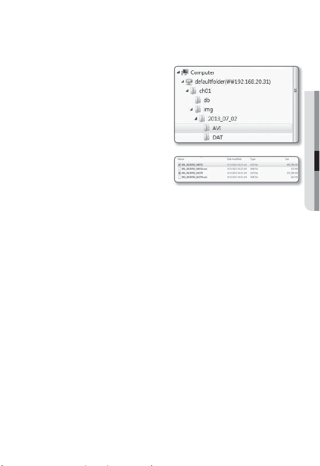
(2) NAS (Network-Attached Storage)
1. In Windows browser, use \\<ip
address>\ to access.
ex)\\192.168.20.31\defaultfolder\ch01\
img\2013_07_02\AVI
2. Go to <Computer> <Network drive
connection> Enter 1.
3. Connected to the NAS.
The directory structure is same as
the directory structure for a Micro SD
memory card.
A filename starts with the format “001_
M
YYYYMMDD_HHMMSS.avi” and the file
number is incremented by one.
YYYYMMDD_HHMMSS indicates the start time of data saving.
“001_YYYYMMDD_HHMMSS.smi” file is a caption file, and you can view it if it exists in the
same directory as its related AVI file.
The max recording time per AVI file is 30 minutes.
If you change or damage the saved data on your own, it will not play back or save properly.
● WEB VIEWER
English _51
Page 52
setup screen
SETUP
You can configure the video, network, event and system settings of the camera in the network.
(
)
]
1. In the Live screen, click [Setup
2. The Setup screen appears.
Microsoft Silverlight 5.0 or higher is required to be installed on the PC for setup pages that provide
J
preview video.
If not installed already, automatically moves to the Silverlight setup.
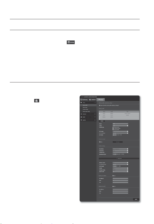
VIDEO SETUP
Video profile
1. From the Setup menu, select the
<Video ( )> tab.
2. Click <Video profile>.
3. Set the <Video profile connection
policy>.
• Keep connection when profile
setting is changed : Changing profile
properties that is used by existing
connection does not affect such
connection and remains with old
profile setup.
If not selected, changing a profile
used by an existing connection
resets such connection.
4. Select each profile properties.
For more details, refer to “To Add/
Change the Video Profile”. (Page
5. Click the input box of each item and
enter / select a desired value.
The context menu may differ depending on
the selected codec type.
• Default profile : If no profile is
selected when using the Web Viewer,
the default video profile is applied.
.
54)
52_ setup screen
Page 53

• E-mail/FTP profile : Video profile to be transferred to the specified email or FTP
site.
Only the MJPEG codec can be set as the E-mail/FTP profile.
• Record profile :
you record video.
6. According to your situation, set ATC (Auto Transmit Control) mode.
• ATC mode : It adjusts the video
properties according to the variance
in the network bandwidth, controlling
the bit rate. Adjusting the bit rate
depends on the ATC mode.
- Control framerate : Reduce the frame rate if the network bandwidth drops down.
- Control compression : Control the compression rate if the network bandwidth
drops down.
Compression adjustment can cause deterioration of the image quality.
If <Bitrate control> is set to <CBR>, the encoding priority according to the ATC mode will be
fixed as below:
Bitrate control / ATC mode Control framerate Control compression
• ATC sensitivity : Affect the transfer rate according to the variance in the network
bandwidth.
The transfer rate will be adjusted to the fastest if the bandwidth is <Very high>,
and adjusted to the latest if the bandwidth is <Very low>.
• ATC limit : If the quality or frame rate is adjusted, the property will be changed to
the applied value (%) against the previous setting value (100%).
Note that if you reduce the property value too much, you may encounter flickering
on the screen. So it is advisable to adjust the value within the threshold.
It is recommended to apply ATC control only for cameras supporting ATC.
J
Set the ATC sensitivity to <Very low> in a network environment with high variance in the network
bandwidth.
If the network connection is unstable, you may encounter flickering on the screen.
7. Select Able or Disable for the Crop Encoding function.
For more details, refer to “To Use Crop Encoding”. (Page
• Crop encoding : It cuts only the selected area out of the full screen and outputs it
at the resolution specified in <Profile setting>.
The resolution should be less than the Crop Encoding setting area.
8. When done, click [Apply (
The profile is applied to your Micro SD memory card or NAS when
CBR Framerate Compression
56)
)].
● SETUP SCREEN
English _53
Page 54

setup screen
To Add/Change the Video Profile
The profile setup can be added or modified to accommodate various profiles depending on
the recording conditions.
1. Select one from the <Video profile> options.
2. Provide the name and select a codec.
3. Specify the conditions under which the codec will be applied.
4. Specify the details of the selected codec including resolution and frame rate.
Click <Advanced> to display the context menu.
• Resolution : Set the video size of the H.264 and MJPEG files.
• Framerate : Set the max number of video frames per sec.
The <Sensor> mode setup in Camera Setup changes the maximum configurable framerate.
M
Sensor 25 fps 30 fps 50 fps 60 fps
Framerate 1~25 fps 1~30 fps 1~50 fps 1~60 fps
• Compression : Specify the compression rate of the video.
• Maximum bitrate : Set the max bit rate of video when the bit rate control is set to
VBR.
As the bit rate can be adjusted limitedly according to the resolution, frame rate and screen
J
complexity, the actual bit rate can be greater than the maximum bit rate. So you must
consider the use conditions when setting the value.
• Target bitrate : Set the target bit rate when the bit rate control is set to CBR.
• Bitrate control : You can select one from constant bit rate and variable bit rate for
compression. Constant bit rate (CBR) varies the video quality and fixes network
transfer bit rate, while variable bit rate emphasizes the quality by varying network
transfer bit rate.
If the bit-rate control is set to the Constant Bit Rate, the actual transmission frame rate
J
may be less than the set frame rate because the Frame Rate First Mode is changed to the
Compression Rate First Mode to ensure the highest image quality at a bit rate which is set
depending on the complexity of the screen.
54_ setup screen
Page 55

• Encoding priority : You can set the video transfer method to Framerate or
Compression.
• GOV length : It specifies the distance (in terms of number of frames) between two
consecutive I-Frames in a video sequence when H.264 codec was selected. (One
I-Frame + 0~Several P-Frames)
• Profile : You can select the H.264 profiling method.
• Entropy coding : Reduce the possible compression loss due to encoding.
• Smart codec : Specify the use of Smart codec.
The Smart Codec will be active only if the codec is of H.264 and the compression system is
M
CBR.
• Multicast(SVNP) : Specify the use of the SVNP protocol.
- IP address : Enter an IPv4 address with which you can connect to the IPv4 network.
- Port : Specify the video communication port.
- TTL : Set the TTL for the SVNP packet.
• Multicast(RTP) : Specify the use of the RTP protocol.
- IP address : Enter an IPv4 address with which you can connect to the IPv4
network.
- Port : Specify the video communication port.
- TTL : You can set the TTL for the RTP packet.
If you set the Multicast address to 224.0.0.0~224.0.0.255, multicast may not work properly
J
in all environments. In that case, we recommend you change the multicast address.
What is GOV length?
GOV(Group of Video object planes) is a set of video frames for H.264 compression,
indicating a collection of frames from the initial I-Frame (key frame) to the next I-Frame.
GOV consists of 2 kinds of frames: I-Frame and P-Frame.
I-Frame is the basic frame for the compression, also known as Key Frame, which contains
one complete image data. P-Frame contains only the data that has changed from the
preceding I-Frame.
For H.264 codec, you can determine the GOV length.
● SETUP SCREEN
English _55
Page 56
setup screen
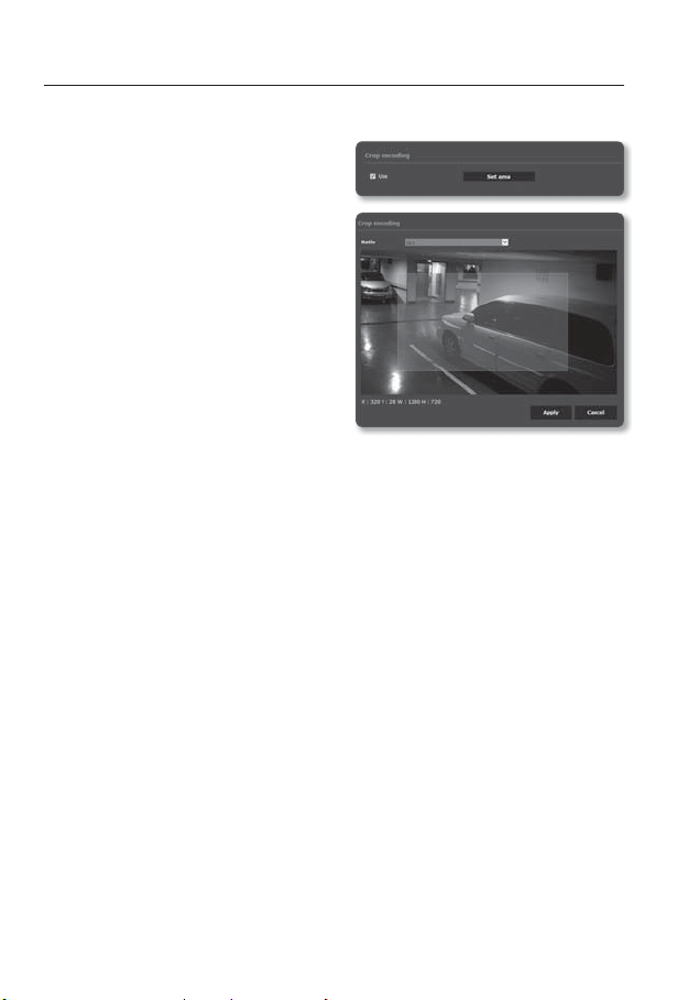
To Use Crop Encoding
1. Select <Use>.
2. Click <Set area>.
The Crop Encoding Area Setup window
will pop up.
3. Select <Ratio>.
• Ratio: It sets up the aspect ratio of
the user specified area.
- 16:9 : The aspect ratio shall be
set to 16:9 as close as to the user
specified area.
The supporting size ranges from
426X240 to 1280X1024 and
supporting output resolutions are
320X180, 640X360, 800X450, and
1280X720.
- 4:3 : The aspect ratio shall be set to 4:3 as close as to the user specified area.
The supporting size ranges from 320X240 to 1280X960 and supporting output
resolutions are 320X240, 640X480, 800X600, 1024X768, and 1280X960.
- Manual : It sets up the aspect ratio of the user specified area.
The supporting size ranges from 320X240 to 1280X1024 and all supporting output
resolutions are available except 1920X1080.
4. Drag the mouse on the screen to specify the Crop Encoding area at your discretion.
If set to <Manual>, the output image may be different from the actual one because of the aspect
J
ratio inconsistency between the Crop Encoding area and the output resolution.
The Crop Encoding area setup can change depending on the DIS setup. Reset the Crop Encoding
area when the DIS setup is changed.
56_ setup screen
Page 57
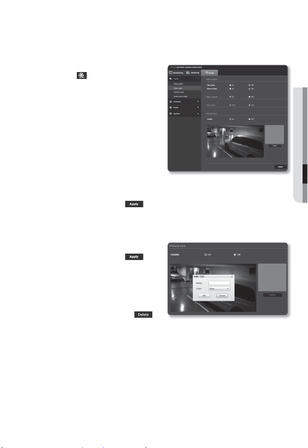
Video setup
1. From the Setup menu, select the
<Video ( )> tab.
2. Click <Video setup>.
3. Select a <Video source> mode.
• Flip mode : Turn upside down
the image that is captured by the
camera.
• Mirror mode : Flip horizontal the
image that is captured by the
camera.
4. Select Able or Disable for the analog
video output.
5. Select the video type.
6. Specify the privacy zone.
7. When done, click [Apply (
To set the privacy zone
You can specify a certain area of the camera video to be protected for your privacy.
1. Set it to <On>.
2. When done, click [Apply (
3. Select 4 vertices on the screen with
your mouse to specify the area.
4. Enter the name and select the color,
and then click [OK].
5. If you want to delete a name in the list,
select one and click [Delete ( )].
)].
)].
● SETUP SCREEN
English _57
Page 58

setup screen
Camera setup
You can change the camera settings according to the environment where the camera is
located.
1. From the Setup menu, select the
<Video (
2. Click <Camera setup>.
3.
Configure the settings as necessary of :
Image preset,
balance, Back light, Exposure, Day/
Night, Special, OSD
4. When done, click [Apply ( )].
If you want to set an image preset
Users can set presets easily.
The selected image preset mode will operate for the active period set by you, and the value
assigned to the mode will be used for the non-active period.
1. Select <Image preset>.
2. Set the <Schedule>.
• Off : Your camera will execute a
• On : Your camera will execute a specific image preset operation for the time
3. Click the [Add ( )] button.
)> tab.
Sensor, SSDR, White
If a certain time (timeout: 240s) is elapsed
your not pressing the [Apply (
button after changing the settings, your
changes will not be applied.
specific image preset operation at all
times.
period set by you on each date.
with
)]
58_ setup screen
Page 59

4. Set the <Mode>.
• Definition focus : This is the factory setting for your camera. Select it for video
recording, focusing on reproducibility.
• Motion focus : Record a moving object clearly. If there are many moving objects,
such as on a road or in a crowded place like a museum, select this option.
Noise level can increase in a low illumination environment, and sensitivity can go down.
J
• Reduced noise : Select this when you need a video with low noise in the low
illumination environment.
• Bright video : This makes the dark area in a full video brighter.
Video contracts effects are reduced.
J
• Motion focus&Reduced noise : Use this when there are many moving objects,
such as on a road or in a crowded place like a museum, or when you need a
video with low noise in a low illumination environment.
• Motion focus&Bright video : Use it when there are many moving objects, such as
on a road or in a crowded place like a museum, or when you need to make a dark
area in full video brighter.
5. Set the operation time.
Initial setting for each image preset mode
Image preset
Definition focus (Default)
When you change the
profile
Motion focus 1/30 1/12000 Default (High) Default (12) 4
Reduced noise 1/15 - Middle Default (12) Default (12)
Bright video Default (1/5) - Default 18 Default (12)
Motion focus&Reduced
noise
Motion focus&Bright video 1/30 1/12000 Default 18 4
Minimum
shutter
Default (1/5) - Default (High) Default (12) Default (12)
Maximum
shutter
1/30 1/12000 Middle Default (12) 4
AGC SSDR SSNR
● SETUP SCREEN
English _59
Page 60

setup screen
The preset setup functions as an aid to users to configure setup. After setting each preset mode,
M
users can freely change and save camera setup modes.
While using the preset mode, if any mode of the preset fails to perform the function for items
changed by the user, they can manually switch to the “Initial setting for each image preset
mode” for each table mode or perform factory resetting to revert to the original setup before use.
If you change the image preset, only shutter/AGC/SSDR/SSNR will be initialized for each mode.
Each preset’s “Camera Setup” is not saved.
To Set the Sensor
It specifies how many frames the camera CMOS sensor will capture per second.
1. Select <Sensor>.
2. Select <Mode>.
Refer to “Video profile” for the framerate
M
setup range of the <Video profile>
according to mode setup. (Page
If the sensor mode is set to 50 fps or 60 fps, the <Back light> mode cannot be set to <WDR>.
To Set SSDR (Samsung Super Dynamic Range)
In a scene where the difference between bright and dark is severe, you can increase the
brightness of the dark area alone to regulate the overall brightness.
1. Select <SSDR>.
2. Set <Mode> to <On>.
3. Configure the <Level> and <D-Range>
settings as necessary.
• Level : Adjust the level of the
dynamic range.
• D-Range : Select the amplitude area of the dynamic range.
52)
60_ setup screen
Page 61

To Set White Balance
You can correct the image colors based on white under any lighting conditions.
1. Select <White balance>.
2. Select <Mode>.
• ATW : Corrects the colors of the
camera video automatically.
• Manual : You can adjust the red and
blue gains of the camera video manually.
• AWC : Corrects the colors of the camera video to be optimized to the current
lighting condition and screen mode.
To obtain the optimal condition for the current lighting, put the focus of the camera
to a white paper and press the [Set AWC] button. If the lighting environment is
changed, you should readjust the settings accordingly.
• Outdoor : Automatically corrects the video colors of the camera to be optimized
to the outdoor environment.
• Indoor : Automatically corrects the video colors of the camera to be optimized to
the indoor environment.
In AWC mode, click the [Set AWC] button if you want to keep the white balance level of the
M
current image.
The white balancing may not work properly in the following conditions:
J
If this is the case, switch to AWC mode.
If the surrounding condition of the object is out of the temperature correction range
-
ex) Clear sky, sunset
If the surrounding of the object is dark
-
If the focus of the camera directly faces the florescent lighting or if the camera is installed in a
-
place of variable illumination, the white balancing operation may be unstable.
● SETUP SCREEN
English _61
Page 62

setup screen
To Set BLC
You can specify a desired area on the video manually and set the area to be displayed
more clearly.
1. Select <Back light>.
2. Set <Mode> to <BLC>.
3. Set <BLC level>.
You can change the level to adjust the
brightness of the monitoring area.
4. Set the <Top, Bottom, Left, Right>
levels to specify the target area.
When BLC is set, the green box is displayed on the screen for 15 seconds.
J
To prevent malfunction at the time of BLC setup, the vertical space of the BLC area should be over
40 and below 60 while the horizontal space over 30 and below 60.
To Set WDR
It displays a sharp image of the objects in a scene where both bright and dark areas exist.
1. Select <Back light>.
2. Set <Mode> to <WDR>.
3. Specify the <WDR level>.
It is recommended to use WDR in the
J
indoor environment.
Noise may exist between the dark area and the bright area in the WDR mode.
If the <Back light> mode is set to <WDR>, the sensor mode cannot be set to 50 fps or 60 fps.
The maximum and minimum shutter values are initialized whenever you turn on or off the WDR
mode.
62_ setup screen
Page 63

To Set Exposure
You can adjust the exposure level of the camera.
1. Select <Exposure>.
2. Select each item and set it properly.
• Brightness : Adjust the screen
brightness.
• Minimum shutter : The limit of the
longest exposure time.
Shutter is the mode to set up the range of the sensor exposure time which will specify the upper
and lower limits for the electronic shutter movement.
The framerate may be reduced in the dark condition if Shutter has a lower value than specified in
the Sensor mode.
• Maximum shutter : The limit of the shortest exposure time.
• Anti flicker : It prevents screen flickering incurring from the dissonance between the
surrounding lighting and the frequency.
• SSNR : Select Able or Disable for the video noise elimination function.
• SSNR level : Adjust the noise reduction level.
• AGC : Select AGC Control mode.
Adjust the gain value of the video (that, in particular, was recorded at a low
contrast scene and had a lower brightness level than normal) to control the video
brightness.
The image exposure can be saturated depending on the Shutter setup range.
J
● SETUP SCREEN
English _63
Page 64

setup screen
To Set Day/Night
1. Select <Day/Night>.
2. Select each item and set it properly.
• Mode: Mode is used to adjust the
color of Color or Black and White.
- Color : The video is always output in
color.
- B/W : The video is always output in
black and white.
- Auto : Normally, it is set to Color but
to B&W under low luminance at night.
If AGC of the <Exposure> menu is set to <Off>, the day/night mode cannot be set to <Auto>.
- Schedule : Set the time during which the camera is operated in the color mode.
• Dwell Time : It specifies the period for which the selected brightness condition
must be maintained to switch the lighting mode from Day to Night or vice versa.
• Duration : It specifies the interval of lighting mode conversion.
• Activation time(Color) : It specifies the schedule for color mode operation.
If it is set, the Color mode is maintained from 00 second of the starting time to 59 second of the
ending time.
64_ setup screen
Page 65

To Setup Special
1. Select <Special>.
2. Select each item and set it properly.
• Sharpness mode : Adjust the overall
sharpness of the image.
If selecting <On>, you can adjust the
sharpness of the image.
• Sharpness level : The higher the level is, the sharper and clearer the outline of the
image becomes.
• Gamma : Adjust the contrast of the image.
• Color level : Adjust the strength of video color.
• Defog : Compensate the video in the foggy or cloudy weather.
It is set to <Off> as a default. Specials are used when the video looks blurry in the
foggy weather.
- Off : Disable the fog elimination function.
- Auto : The image is automatically compensated according to the foggy level.
Adjust <Defog level> to be more effective.
- Manual : The user manually sets the amount of compensation for each image.
If the defog mode is set to <Auto>, the performance is proportional to the fog level. To keep
J
the set defog level without regard to the fog level, set the defog mode to <Manual>.
If the manual defog level is high in a thin fog, the image may become too dark.
• Defog level : Control the defog level.
• DIS : Compensates the image automatically when it is seen to shake for stable
image output.
Mitigate the degree of image vibration when the camera vibrates due to the external factors
M
such as wind.
● SETUP SCREEN
English _65
Page 66

setup screen
To Set OSD
1. Select <OSD>.
2. Select each item and set it properly.
• Title overlay : It specifies if the
camera name shall be displayed on
the screen.
• Camera title : It specifies the name
of the camera to be displayed on the
screen.
• Title position X, Y : It specifies the position of the camera name on the screen.
• Time display : Specify the use of time display on the screen.
• Date notation : Specify the date format that will be displayed on the screen.
• Time position X, Y : Specify the position of time display on the screen.
• Weekday overlay : Specify the use of date display date on the screen.
• Size : It specifies the size of the text displayed on the screen.
Depending on the video output resolution and the OSD size, the OSD location can be automatically
J
adjusted.
66_ setup screen
Page 67
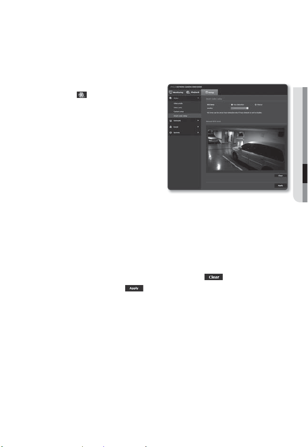
Smart codec setup
Set a desired area of the video incoming from the camera as ROI area and specify the
detection sensitivity for the area.
1. From the Setup menu, select the
<Video (
2. Click <Smart codec setup>.
3. Select ROI Area.
• Face detection : Active if a face is
J
• Manual : Specify the ROI area to monitor manually.
4. Set the image quality.
The ROI area will be displayed in the specified quality.
5. If you want to set the area of your interest by <Manual>, first, select the area with
your mouse and drag it.
6. To cancel all the settings for the area, click the [Clear (
7. When done, click [Apply (
J
)> tab.
recognized on the monitoring screen.
You can detect max 35 faces on the
screen at the same time.
The minimum size of detectable face
is 45x45 (horizontal x vertical) pixels
for the given max resolution. But there
may be some errors depending on the
characteristics of your face or lighting.
You can specify up to 5 distinct areas.
)] button.
)].
The Smart codec will not be active if it is set to <Off> in <Video profile>. (page 52)
Go to <Event> <Event setup> <Face detection> and change it to <Enable> to set the
desired area for facial detection.
● SETUP SCREEN
English _67
Page 68
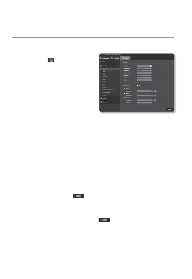
setup screen
NETWORK SETUP
Interface
1. From the Setup menu, select the
<Network (
2. Click <Interface>.
3. Set the <Interface> and <IPv6 setup>
as necessary.
• IP type : Select an IP connection type.
- Manual : Specify the IP address,
Subnet mask, Gateway, DNS1,
and DNS2.
- DHCP : Specify the DNS1 and
DNS2.
- PPPoE : Specify the DNS1, DNS2, ID and Password.
If you set it to <Manual>, you should specify the IP, Subnet mask, Gateway, DNS 1 & 2 manually.
• MAC address : Shows the MAC address.
• IP address : Displays the current IP address.
• Subnet mask : Displays the <Subnet mask> for the set IP.
• Gateway : Displays the <Gateway> for the set IP.
• DNS1/DNS2 : Displays the DNS(Domain Name Service) server address.
4. Set the <IPv6 setup>.
Set to <Use> to use IPv6 address.
• Default : Use the default IPv6 address.
• DHCP : Display and use the IPv6 address obtained from the DHCP server.
• Manual : Enter IP address and gateway manually and use it.
5. When done, click [Apply ( )].
)> tab.
The IP addressing system will be defaulted to DHCP. If no DHCP server is found, the previous
J
settings will be restored automatically.
Once completed with editing, click [Apply ( )] to apply changes and the browser exits.
After a while, connect again with the changed IP.
68_ setup screen
Page 69
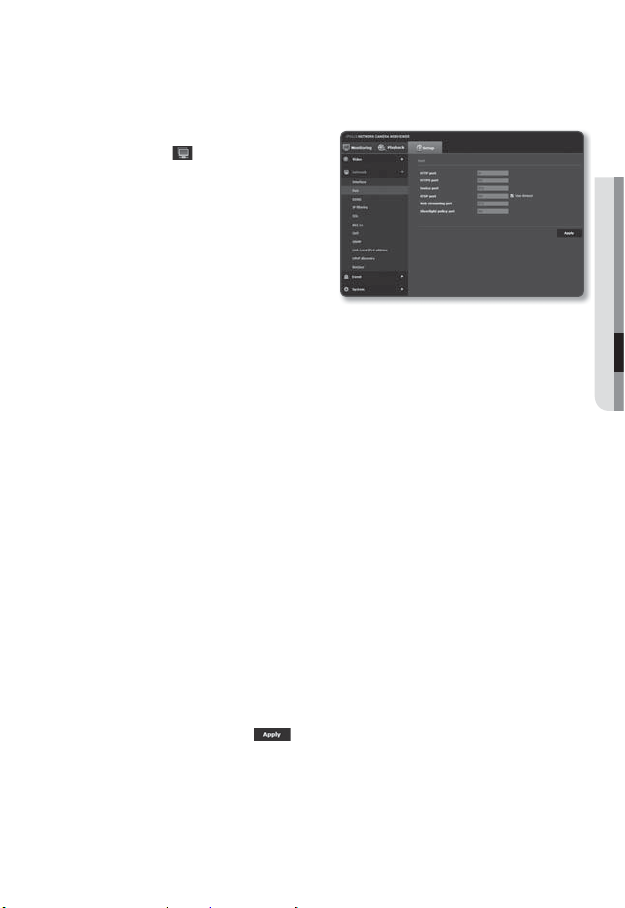
Port
1. From the Setup menu, select the
<Network ( )> tab.
2. Click <Port>.
3. Type in each item in the Port menu as
necessary.
When setting your ports, you cannot use port
numbers such as 0~1023, 3702 or 49152.
• HTTP port : HTTP port used to
access the camera via the web
browser.
The default is 80(TCP).
Setting the HTTP port for Safari and Google Chrome browsers to 65535 is not allowed by security
policy.
• HTTPS port : It is the more secure version of HTTP, web communication protocol.
In SSL, set the HTTPS mode for use. The initial value is 443(TCP).
The permitted setting range is 1024 to 65535. (For the security reasons, in google chrome
browser, you cannot set the HTTPS port to 65535 for access.)
• Device port : Set a port used to transfer video signals with the Samsung
protocols.
• RTSP port : Used to transfer videos in the RTSP mode; the default is 554.
• Web streaming port : Used to transfer videos to the Web Viewer; the default is 4520.
• Silverlight policy port : Silverlight is used to permit to acquire a network
connection; the default is 943.
If changed the HTTP port, the browser exits.
M
Afterwards, address should contain the newly assigned HTTP port trailing the IP.
ex) IP address: 192.168.1.100, HTTP port : Assigned 8080 http://192.168.1.100:8080
(If HTTP port is set to 80, no need to specify the port number)
The port range of the Web Streaming is between 4502 and 4534. If the Device port is with this
effective range, the Web Streaming port should be specified the same as the Device port.
You cannot change the Web Streaming/Silverlight policy server port of a camera.
4. When done, click [Apply (
)].
● SETUP SCREEN
English _69
Page 70
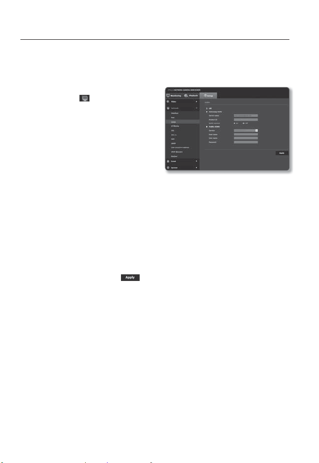
setup screen
DDNS
DDNS is an abbreviation of Dynamic Domain Name Service that converts the IP address of
a camera into a general Host Name so that the user can easily remember it.
1. From the Setup menu, select the
<Network (
2. Click <DDNS>.
3. Select the <DDNS> connection type.
4. Type in the DDNS items according to
the selected type.
• Samsung DDNS : Select this if you
use the DDNS server provided by
Samsung Techwin.
- Product ID : Enter the product ID that is registered with the Samsung DDNS
service.
- Quick connect : It sets port forwarding automatically when used with a UPnP
(Universal Plug and Play) supporting router.
• Public DDNS : Select one of provided public DDNS servers when you use a public
DDNS server.
- Service : Select desired public DDNS service server.
- Host name : Enter the name of the host that is registered with the DDNS server.
- User name : Enter the user name for the DDNS service.
- Password : Enter the password for the DDNS service.
5. When done, click [Apply (
J
)> tab.
)].
If selected <Quick connect>, be sure to select Samsung DDNS service.
70_ setup screen
Page 71
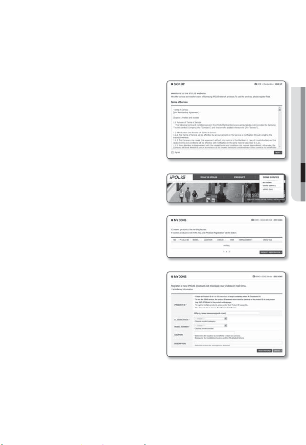
Registering with DDNS
To register your product with the Samsung DDNS
1. Visit the iPOLiS web site
(www.samsungipolis.com) and sign in
with a registered account.
2. From the top menu bar, select <DDNS
SERVICE> - <MY DDNS>.
3. Click [PRODUCT REGISTRATION].
4. Enter the product ID.
You must perform the duplicate check for the
ID that you entered.
5. Select a <CLASSIFICATION> and
specify the <MODEL NUMBER>.
6. Specify the product location with a
description if necessary.
7. Click [REGISTRATION].
The product will be added to the
product list that you can check.
● SETUP SCREEN
English _71
Page 72
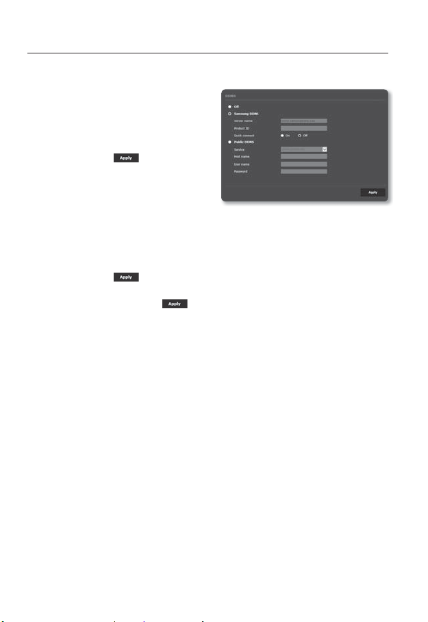
setup screen
To connect to the Samsung DDNS in camera setup
1. From the DDNS setup page, set
<DDNS> to <Samsung DDNS>.
2. Provide the <Product ID> that you
registered product ID with the DDNS
site.
3. Click [Apply (
When the connection is successfully
made, you will see the message of
<(Success)> on the screen.
Configuring public DDNS in Camera Settings
1. Open the DDNS settings page and select <Public DDNS> for <DDNS>.
2. Enter the corresponding site’s host name, user name and password.
3. Click [Apply (
If the connection properly establishes, <(Success)> appears.
4. When done, click [Apply (
To use DDNS service properly, both DDNS setup and the router’s port forwarding setup are
M
required.
For port forwarding setup, refer to “Port Range Forward (Port Mapping) Setup”. (page
)].
)] button.
)].
32)
72_ setup screen
Page 73
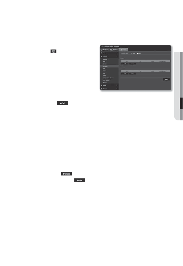
IP filtering
You can create a list of IPs that you want to grant or deny access to them.
1. From the Setup menu, select the
<Network (
2. Click <IP filtering>.
3. Select <Filtering type>.
• Deny : If selecting this, access from
those IPs that are added to the
filtering will be restricted.
• Allow : If selecting this, access from
only those IPs that are added to the
filtering will be accepted.
4. Click the [Add (
The IP list will be created.
5. Provide the IP that you want to grant or deny access from.
When you enter an IP address and a Prefix, the list of IP addresses available will
appear in the right-side filter range column.
M
6. Select an IP to delete from the list.
Click the [Delete (
7. When done, click [Apply ( )].
)> tab.
)] button.
If selected <Allow> for IP Filtering and <IPv6 setup> of <Interface> is set to <Use>, both IPv4
and IPv6 addresses of the computer currently configuring should be assigned.
The IP address of the computer used for the current setup cannot be added to <Deny>, it should
be added to <Allow>.
Only the IP addresses that are set to <Use> will be displayed in the filter column.
)] button.
● SETUP SCREEN
English _73
Page 74

setup screen
SSL
You can select a secure connection system or install the public certificate for this purpose.
1. From the Setup menu, select the
<Network (
2. Click <SSL>.
3. Select a secure connection system.
To access the camera using HTTPS mode, you
have to type the IP address for the camera in
the form of “https://<Camera_IP>”.
If you failed to configure the Web viewer
settings in HTTPS mode with Internet Explorer,
edit the Internet options as follows: <Menu
Tools Internet Options Advanced Security Uncheck TLS 1.0, and check TLS 1.1, TLS 1.2>
4. Search for the public certificate that you want to install on the camera.
To install the certificate on the camera, you need to provide a certificate name (it
can be arbitrarily assigned by the user), certificate file issued from the certification
authority and a key file.
The <HTTPS (Secure connection mode using the public certificate)> item will be active only if
there exists a public certificate installed.
5. When done, click [Apply (
Installing the certificate
1.
Enter the certificate name.
2.
Select the certificate file to be installed and certificate key, and click [Install ( )]
button.
Deleting the certificate
1. Click [Delete ( )] button.
2. To delete a public certificate, you should access the network video decoder in
the mode of <HTTP (Do not use secure connection)> or <HTTPS (Secure
connection mode using a unique certificate)>.
)> tab.
)].
74_ setup screen
Page 75
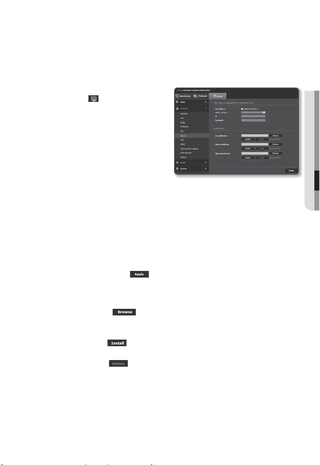
802.1x
When connecting network, you can choose whether using 802.1x protocol, and then install
the certification.
1. From the Setup menu, select the
<Network (
2. Click <802.1x>.
3. Set the <IEEE 802.1x setting(EAPOL
using EAP-TLS)>.
• Enable IEEE 802.1x : Specify the use
of the 802.1x protocol.
• EAPOL version : Select version 1 or 2.
• ID : Enter the client certificate ID.
• Password : Enter the client private
key password. If the key file used is not encrypted, you don’t need to enter it.
J
4. Install/remove the certificate.
• CA certificates : Select a public certificate that contains the public key.
• Client certificate : Select a public certificate that contains the client certificate key.
• Client private key : Select a public certificate that contains the client private key.
5. When done, click [Apply (
To install/remove 802.1x related certificates
1. Press the [Browse ( )] button for each item and select a certificate to install.
2. If no certificate is installed, you will see “Not Available” appearing next to the selected
item.
3. Press the [Install (
next to the item.
4. Press the [Delete ( )] button to remove the certificate.
)> tab.
If the connected network device does not support the 802.1x protocol, the protocol will not
operate properly even if you set it.
)].
)] button to start installation with a message of “Installed”
● SETUP SCREEN
English _75
Page 76

setup screen
QoS
You can specify the priority to secure a stable transfer rate for a specific IP.
1. From the Setup menu, select the
<Network (
2. Click <QoS>.
3. Click the [Add (
The IP list will be created.
4. Enter an IP address to which you will
apply QoS.
M
5. Select an IP to delete from the list.
Click the [Delete (
6. When done, click [Apply ( )].
SNMP
With the SNMP protocols, the system or network admin can monitor the network devices
on a remote site, and configure the environment settings.
1. From the Setup menu, select the
<Network (
2. Click <SNMP>.
3. Specify the <SNMP>.
• Enable SNMP v1 : SNMP version 1
will be active.
• Enable SNMP v2c : SNMP version 2
will be active.
- Read community : Provide the
name of the read community where
you can access to the SNMP information.
The default name is <public>.
- Write community : Provide the name of the write community where you can
access to the SNMP information. The default name is <write>.
)> tab.
)] button.
The default prefix for IPv4 is 32;
For DSCP, the default is set to 63.
Only the IP addresses that are set to <Use> can be prioritized.
)] button.
)> tab.
76_ setup screen
Page 77

• Enable SNMP Trap : SNMP trap is used to send important events and conditions
to the Admin.
- Community : Enter the trap community name to receive messages.
- IP address : Enter the IP address to which messages will be sent.
- Authentication failure : It specifies whether an event shall be generated when the
community information is invalid.
- Network connection : It specifies whether an event shall be generated when the
network disconnection is restored.
• Enable SNMP v3 : SNMP version 3 will be active.
- Password : Specify the default password for SNMP version 3. The default
password is <admin4321>.
The default password can be exposed to a hacking thread so it is recommended to change the
password after installing the product.
Note that the security and other related issues caused by the unchanged password shall be
responsible for the user.
Password should be longer than 8 characters, no more than 16 characters.
4. When done, click [Apply (
SNMP v3 is only able to be set when the secure connection mode is HTTPS.
J
Refer to “SSL”. (page
)].
74)
Link-Local IPv4 address
An additional IP address may be assigned to assess the camera from the Link-Local
network.
1. From the Setup menu, select the
<Network (
2. Click <Link-Local IPv4 address>.
3. Set the <Link-Local IPv4 address>.
• Auto configure : It specifies Able
or Disable for the Link-Local IPv4
address.
• IP address : Display the assigned IP
address.
• Subnet mask : Display the subnet
mask of the assigned IP.
4. When done, click [Apply (
)> tab.
)].
● SETUP SCREEN
English _77
Page 78

setup screen
UPnP discovery
Cameras can be automatically searched in the client and operating system in support of
the UPnP protocol.
1. From the Setup menu, select the
<Network (
2. Click <UPnP discovery>.
3. Set the <UPnP discovery>.
• UPnP discovery : It specifies Able or
Disable for UPnP Discovery.
• Friendly name : Display the camera
name.
Friendly name is displayed in the
format of SAMSUNG-<Model
Name>-<MAC Address>.
M
4. When done, click [Apply (
Bonjour
Cameras can be automatically searched in the client and operating system in support of
the Bonjour protocol.
1. From the Setup menu, select the
<Network (
2. Click <Bonjour>.
3. Set the <Bonjour>.
• Bonjour : It specifies Able or Disable
for Bonjour.
• Friendly name : Display the camera
name.
Friendly name is displayed in the
format of SAMSUNG-<Model
Name>-<MAC Address>.
4. When done, click [Apply (
)> tab.
In the Windows operating system which basically supports UPnP, the cameras connected to the
network are displayed.
)].
)> tab.
)].
In the Mac operating system, which support Bonjour by default, the connected cameras are
M
automatically displayed in the Bonjour bookmark of the Safari web browser.
If the Bonjour bookmark is not displayed, check Bookmarks Setup in the “Preference” menu.
78_ setup screen
Page 79

EVENT SETUP
FTP / E-mail
When an event occurs, you can set the FTP/email server to send an image recorded by
your camera.
1. From the Setup menu, select the
<Event (
2. Click <FTP / E-mail>.
3. Select <FTP configuration> or
<E-mail configuration> and enter /
select a desired value.
• FTP configuration
)> tab.
- Server address : Enter the IP
address of the FTP server to send
an event image.
- ID : Enter the user ID with which
you will log in to the FTP server.
- Password : Enter the user account
password for logging into the FTP
server.
- Upload directory : Set the FTP account path to send an event image.
- Port : The default port of the FTP server is 21; however, you can use a different
port number according to the FTP server settings.
- Passive mode : Select <On> if you need to connect in passive mode due to the
firewall or the FTP server settings.
● SETUP SCREEN
English _79
Page 80
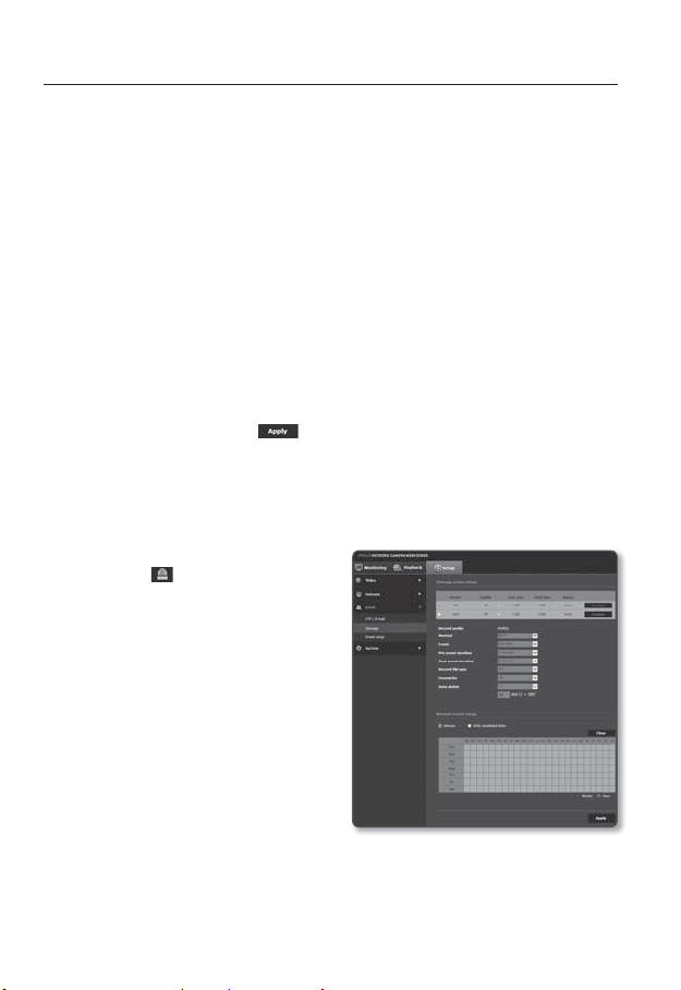
setup screen
• E-mail configuration
- Server address : Enter the IP address of the e-mail server to send an event
image.
- Use authentication : Select whether to use authorization.
- Use SSL : Specify the use of SSL.
- ID : Enter the user ID for logging into the email server.
- Password : Enter the user account password for logging into the email server.
- Port : The default port of the email server is 25; however, you can use a different
port number according to the email server settings.
- Recipient : Enter the address of the email recipient.
- Sender : Enter the address of the email sender. If the sender address is
incorrect, the email from the sender may be classified as SPAM by the email
server and thus may not be sent.
- Subject : Enter a subject for your email.
- Body : Provide the text for the massage. Attach an event image to your email.
4. When done, click [Apply (
Storage
You can activate recording on your device, set the recording conditions, check the saved
data capacity and format the device itself.
1. From the Setup menu, select the
<Event (
2. Click <Storage>.
3. Select a device to save data in.
M
)> tab.
If your device is properly recording data, it
will display “Recording”.
)].
80_ setup screen
Page 81

To make recording on the Micro SD memory
1. Check the memory card’s <Free size> and <Total size>.
2. Otherwise, check the stored data and if you find them not important, then click
<Format> to format the Micro SD memory.
Some frames may be skipped if the micro SD memory card operates at the lower speed than
recommended.
For more details, refer to “Recommended Micro SD/SDHC/SDXC Memory Card Specifications”.
(Page 10)
For a Micro SD memory card with a large capacity, the formatting will be slowed down accordingly.
The data traffic will increase when the camera is set to higher resolution, higher bit rate, and/or higher
framerate.
If there is too much data traffic, some frame may be skipped although it is stored in a full frame.
When a frame skip occurs, images are saved at the rate of min. one image per sec.
3. Specify the storage action.
• Record profile : Shows recording profile’s codec type.
• Normal : Make recording at a certain frame rate.
• Event : Set the recording type for a certain event that occurs.
• Pre event duration : Specify the time point before the occurrence of the alarm;
starting from the time point, the images will be transferred. You can specify up to
5 seconds before the occurrence of the alarm.
• Post event duration : Specify the time point after the occurrence of the alarm; to
the specified time point, the images will be transferred. You can specify up to 120
seconds after the occurrence of the alarm.
• Record file type : It specifies the file format of the recorded images.
If you insert a SD card saved in another saving file type (AVI/STW), you will need
to format it before use.
- STW : It is Samsung Techwin’s unique file format.
- AVI : It is the conventional avi format.
• Overwrite : If the Micro SD memory is full, this will delete old data and store new
data in replacement.
• Auto delete : Data for a certain period is deleted, while other data is not deleted.
This can be set within the range of one day to 180 days.
If the storage period is expired, data is automatically deleted and new data will be recorded.
J
Once deleted, it cannot be recovered.
● SETUP SCREEN
English _81
Page 82

setup screen
4. Specify the <Normal record setup>.
• Always : Always save recorded video in the Micro SD memory card.
If set to Always, the activation time cannot be changed.
• Only scheduled time :
• [Clear ( )] : Reset all settings.
5. When done, click [Apply (
If you want to record in your NAS
1. Set the saving operation and basic
recording.
Auto deletion is supported only if your NAS
J
meets the recommended specifications.
2. Enter the information registered in your
NAS.
• IP address : Unique IP address
assigned to the NAS.
• ID : An ID registered in the NAS.
• Password : Password registered in
the NAS.
• Default folder : Designate the NAS
user folder to save data in.
3. Click the [Test] button to see if you can
successfully connect to the NAS.
If the success message is displayed, it
J
means that you can successfully save data in the NAS.
If the fail message is displayed, check the following.
Confirm that the IP address of the NAS is valid.
-
Confirm that the ID/password of the NAS is valid.
-
Confirm that you can access the folder designated as the default folder using the ID of the
-
NAS.
Confirm that the NAS SMB/CIFS items are unchecked.
-
Records only on the specified time of the specified day of week.
)].
82_ setup screen
Page 83

Confirm that the NAS IP address and the camera IP address are in the same format.
-
ex) The NAS & camera subnet mask initial value is 255.255.255.0.
If the IP address is 192.168.20.32 then the NAS IP address should be in the range of
192.168.20.1~192.168.20.255.
Check whether you tried to access as another user without formatting the default folder saved
-
or used.
Confirm that you used recommended NAS equipment.
-
4. Once the setting is complete, change the setting of the NAS from <Off> to <On>
and click the [Apply (
5. Access the NAS to check the available capacity and the total capacity.
6. If the capacity is insufficient, check the data and click the [Format] button to format
the NAS on your own.
Due to network access errors, you might be unable to save the NAS temporarily.
The data traffic will increase when the camera is set to higher resolution, higher bit rate, and/or higher
framerate.
If there is too much data traffic, some frame may be skipped although it is stored in a full frame.
When a frame skip occurs, images are saved at the rate of min. one image per sec.
)] button.
● SETUP SCREEN
English _83
Page 84
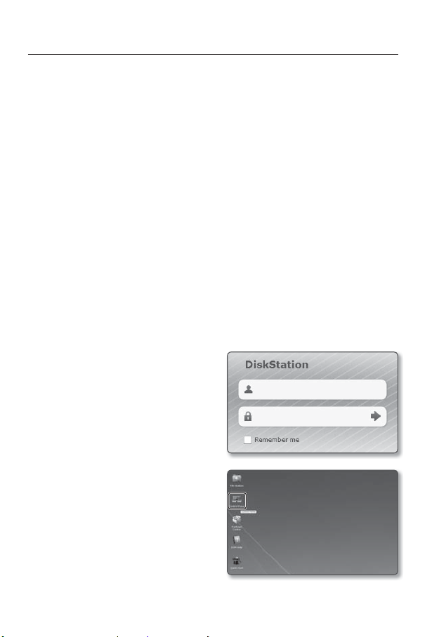
setup screen
NAS (Network Attached Storage) guide
When you use the NAS, you might be unable to save data due to temporary network
J
disconnections.
If the setting allows a Micro SD memory card and the NAS to be simultaneously connected for
use, the higher priority for recording goes to the NAS.
If you activate Overwrite to the NAS by setting it to <On> and the available capacity is below 1%,
it will be saved in the micro SD card.
If you are saving data in the NAS, you might be unable to save it when you insert a Micro SD
memory card used by another camera.
NAS recommended specs : Refer to “NAS recommended specs”. (Page 11)
If you change the NAS saving while saving data in the NAS, it will not be reflected in the system
immediately.
If you remove NAS equipment on your own while saving data, or if the network is disconnected,
NAS saving operation will be terminated abnormally.
As a rule of thumb, you are recommended to use one NAS sharing directory per camera without
duplicated use.
The following is a description of how to save data using the NAS according to the Synology
NAS method, which is one of the recommended products.
1. Access the Synology NAS as an admin.
In this example, the NAS IP Address is
set to [192.168.20.253].
2. If you access it as an admin, the
following screen will be displayed. Click
the [Control Panel].
84_ setup screen
Page 85
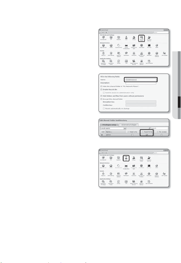
3. Click the <Shared Folder> in the file
sharing and privilege menu.
4. Click the [Create] button.
5. After entering the shared folder
name(ID), click the [OK] button to
create a shared folder.
In this example, the shared folder name
is [testDirectory].
6. In Windows, for NAS access, set
the privilege for the shared folder as
follows.
Check the admin’s [Read/Write].
7. Click on the <User> in the file sharing
and privilege menu.
● SETUP SCREEN
English _85
Page 86
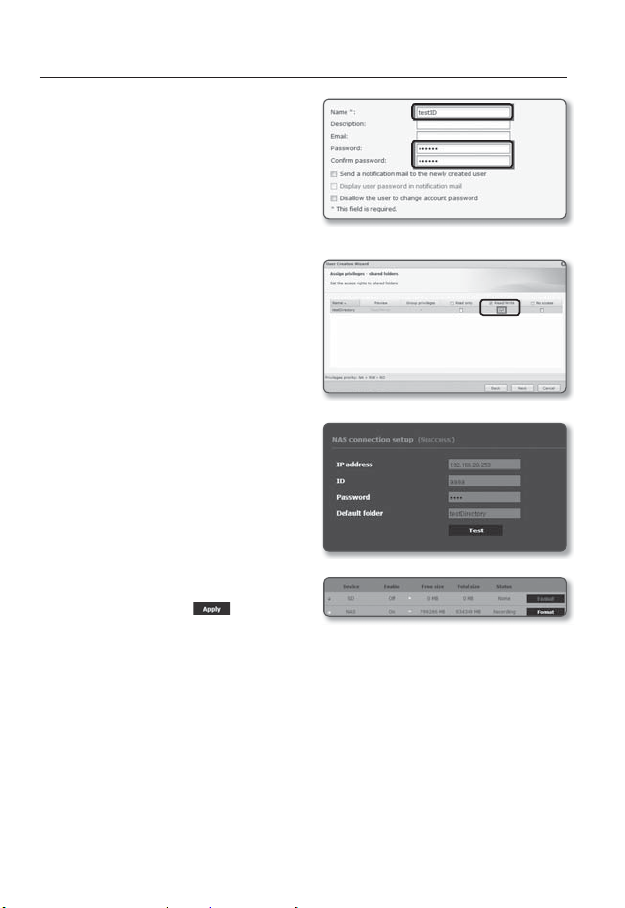
setup screen
8. After clicking the [Create] button, enter
name(ID) and password.
In this example, name(ID) is set to
[testID] and password is also set to
[testID].
According to the NAS recommendations,
J
when you use Netgear’s NAS equipment,
do not allocate the capacity for use.
9. In Windows, set the privilege for NAS
access.
For the shared folder created in step
4 called “testDirectory” check [Read/
Write].
10. Basic setting in the NAS is completed.
Connect your camera to the actual
NAS.
As shown below, enter the NAS
connection setting items.
11. After entering item 10, check <On>.
12. Click the [Apply (
Finish saving by using the NAS.
)] button.
86_ setup screen
Page 87
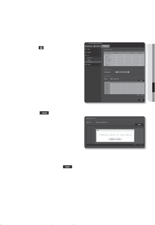
Time schedule
You can set to save the video data at a certain interval as scheduled regardless of the
actual occurrence of the event.
1. From the Setup menu, select the
<Event (
2. Click <Event setup>.
3. Select <Time schedule> from <Event
action setup>.
4. Set whether or not to <Enable>.
5. Specify the <Transfer interval>.
6. Specify the <Activation time>.
• Always : Runs the specified operation
• Only scheduled time : Operation is
• [Clear (
• Minute : Click an area in Activation
• Hour : Drag your mouse at Activation
J
7. Set the operational conditions.
• FTP : Set whether to perform FTP transmission at the designated time.
8. When done, click [Apply (
)> tab.
always.
If set to <Always>, the activation time
cannot be changed.
executed periodically on the set days/time.
Time and set the time by minutes.
Time and set the time by hours.
)] : Reset all settings.
The transfer interval setting value must be
smaller than the preset activation interval
to succeed in image transmission.
)].
● SETUP SCREEN
English _87
Page 88
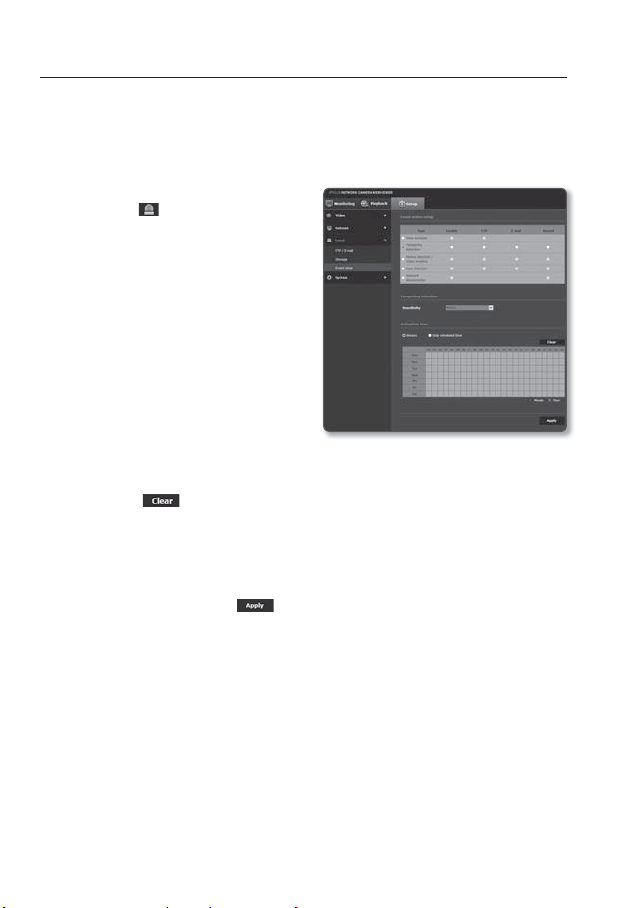
setup screen
Tampering detection
You can set to detect tampering attempts and trigger events, such as sudden change
of camera’s framing direction, blocked lens and other overall change of scenes from the
video.
1. From the Setup menu, select the
<Event ( )> tab.
2. Click <Event setup>.
3. Select <Tampering detection> from
<Event action setup>.
4. Set whether or not to <Enable>.
5. Set the tampering detection sensitivity.
The higher the sensitivity, detects the
minutest tampering attempts.
6. Specify the <Activation time>.
• Always : Always check whether
an event occurs. When an event
occurs, the designated operation is
executed.
• Only scheduled time : On the designated date/time, periodically check whether an
event occurs. When an event occurs, the set operation is executed.
• [Clear (
7. Set the operation which will be executed when an event occurs.
• FTP : Specify whether to perform FTP transmission when an event occurs.
• E-mail : Specify whether to perform e-mail transmission when an event occurs.
• Record : Specify whether to save in the SD memory card when an event occurs.
8. When done, click [Apply (
J
)] : Deselect the selected times.
)].
The default tampering detection function may not work properly in the following cases:
Under circumstances of simple background or low illumination and night time may lower the
-
detection sensitivity.
A severe shaking of the camera or a drastic change to the illumination can be considered a
-
tampering by mistake.
Detection of the tampering may take some time (maximum 5 seconds) right after the
-
tampering was made.
Once a tampering is detected, the camera will resume a normal operating after a certain
-
stability time (approx. 5 seconds) during which no detection will be performed.
88_ setup screen
Page 89
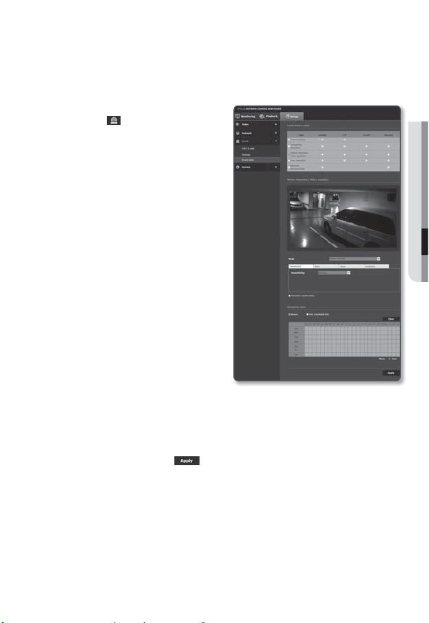
Motion detection / Video analytics
Events of motion detection and video analysis can be set to trigger event signal output.
1. From the Setup menu, select the
<Event (
2. Click <Event setup >.
3. Select <Motion detection / Video
analytics> from <Event action
setup>.
4. Set whether or not to <Enable>.
5. According to your purpose, select from
motion detection and intelligent video
analysis.
6. Set <Sensitivity>, <Size> and <Area>.
When selected Intelligent Video
Analysis, set <Analytics> too.
7. Set whether to use <Detection result
overlay>.
When a motion is detected, its size and
position is marked with a rectangle on
the screen.
• Green : All targets detected as
• Red : It is an object judged to have
8. Specify the activation time and activation condition.
9. When done, click [Apply (
)> tab.
moving.
passed, entered or escaped (with the
color maintained for 1 or 2 seconds)
or to have appeared or disappeared (with the color maintained for 3 to 5 seconds).
For more information about <Activation time> and <Action>, refer to “Tampering detection”.
(page
88)
)].
● SETUP SCREEN
English _89
Page 90

setup screen
Motion detection and Video analytics cannot be used simultaneously.
J
Before using, set the minimum and maximum motion sizes to suit desired motion range to be
detected.
Detected size of an object may have difference with the actual size according to its shape.
Up to 16 objects from the top side of the screen can be displayed.
If camera is capturing a close object, the video analysis capability may degrade.
In the following cases, motion detection and intelligent video analysis function may be degraded
or cause improper detection.
The object color or brightness is similar to the background.
-
Small activities around the border area of the camera’s field of view.
-
Multiple movements continue occurring at random due to a scene change, rapid lighting
-
changes or other reasons.
A fixed object continues moving in the same position.
-
Motions of less position changing such as approaching to the camera or fading away from the
-
camera.
Moving object approaches to the camera too close
-
An object hides other objects behind.
-
Two or more objects overlap or one object divides in multiple portions.
-
Too fast object (for a proper detection, one object should be found overlapping between
-
contiguous frames).
Reflection / blur / shadow due to a strong light such as direct sunlight, illumination, or headlamp.
-
In severe snow, rain, wind or in dawn / dusk.
-
90_ setup screen
Page 91

To use Motion detection
It detects a motion that meets all conditions specified by sensitivity, size and area.
1. Select a motion detection mode.
2. Select <Sensitivity> tab to set the
sensitivity level. You can set the sensor’s
sensitivity to detect a motion out of the
background from the monitoring video.
In a situation that definitely distinguishes
J
objects out of backgrounds, set this to
a low sensitivity level. For opposite case
that is hard to distinguish objects like low
illuminated situation, set this to a high
level.
3. Select <Size> tab.
You can limit the minimum/maximum
size of motion to be detected.
• Minimum Size : To set the minimum
size of detected motions, select
<Minimum Size> and then point
and drag to the desired size on the
screen using the mouse.
• Maximum Size : To set the maximum
size of detected motions, select
<Maximum Size> and then point
and drag to the desired size on the screen with your mouse.
Motions smaller than the specified minimum size or bigger than the maximum size are not
J
detected. To avoid unintended detections caused by great and small noises, set minimum/
maximum motion sizes appropriately in accordance to your environments.
Note that same motions on the same location can be differently detected in their detection size;
it is recommended to consider and include the tolerable difference when setting the minimum/
maximum detection sizes.
● SETUP SCREEN
English _91
Page 92

setup screen
4. Select <Area> tab.
You can specify an area on the screen
to include or exclude the area to/from
detection.
You can specify up to 4 areas.
• Detection area : Sets the entire
screen as excluded from detection,
and adds specified area as motion
detection area. Select 4 vertices in
the image with your mouse to specify
the detection area.
• Non detection area : Sets the entire
screen as motion detection area, and
excludes specified area as not to
be detected. Select 4 vertices in the
image with your mouse to specify the
non-detection area.
5. To delete an area, right click on the
screen to open popup context menu
and select Delete, and [OK] button.
6. When done, click [Apply (
)].
92_ setup screen
Page 93

To use Video analytics
It detects event that meets all conditions specified by sensitivity, size and area and the
event condition rules.
1. Select the video analysis mode.
2. Set <Sensitivity>, <Size> and <Area>.
For further details on settings, refer
to “To use Motion detection”. (Page
91~92)
3. Select <Analytics> tab.
4. Select the video analysis type.
• Passing : It will detect objects
passing by the line set by a user.
• Entering/Exiting : It will detect objects
coming in or out of the area set by a
user.
• Appearing (Disappearing) : Detects
motions of appearing on or
disappearing from the user-defined
area or the entire screen area.
5. Set the video analysis rules.
For further details on settings, refer to
“To set the video analysis rules”.
94~95)
(page
6. Set whether to use <Detection result
overlay>.
Specified rules of virtual lines and areas
are displayed on the monitoring page.
7. When done, click [Apply (
)].
● SETUP SCREEN
English _93
Page 94

setup screen
To set the video analysis rules
Passing
1. Set the type to <Passing>.
2. On the screen, click on preferred
starting and ending point of the virtual
line, then a popup window appears.
3. Select the desired rule:
• Right: Detects motions of moving
from the left to the right, over the
virtual line.
• Left: Detects motions of moving from
the right to the left, over the virtual
line.
4. Click [OK].
5. To remove a defined rule, right click on the displayed virtual line to open popup
context menu and select [Delete] button.
Entering/Exiting
1. Set the type to <Entering/Exiting>.
2. On the screen, click four vertices to
define detection area and a popup
window appears.
3. Select the desired rule:
• Entering : Detects motions of moving
object whose center point entering
into the defined area, from outside of
the area.
• Exiting : Detects motions of moving
object whose center point exiting
from the defined area, from inside of the area to outside.
4. Click [OK].
5. To remove a defined rule, right click on the displayed side lines of the area to open
popup context menu and select [Delete] button.
94_ setup screen
Page 95

Appearing (Disappearing)
1. Set the analysis type to <Appearing
(Disappearing)>.
2. Select the desired event rule:
• Defined
Area Based Rules : It detects
event of appearing object that
appears in the area and remaining
for a certain time period while not
passing through the area borders,
and opposite case of disappearing of
objects existed in the area.
On the screen, click four vertices to
define detection area.
Select the <Appearing(Disappearing)> from the popup.
Area Based Rules : If there is
• Entire
new object in the full area for a while
or an object that was in the full area
disappears, it will be detected.
Click on the <Entire area based
rules> menu to select a rule in the
pop up window.
3. Click [OK].
4. To remove a defined rule, right click on
the displayed side lines of the area or
on the screen to open popup context
menu and select [Delete] button.
● SETUP SCREEN
English _95
Page 96
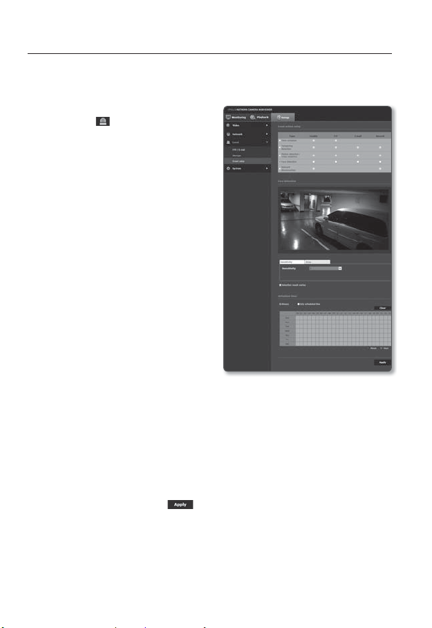
setup screen
Face detection
You can set to detect recognized face and trigger an event accordingly.
1. From the Setup menu, select the
<
Event ( )> tab.
2. Click <Event setup>.
3.
Select <
Face detection> from <Event
action setup>.
4.
Set whether or not to <Enable>.
5. Select <Sensitivity> tab to set the
sensitivity level.
As the sensitivity grows, face detection
becomes more close and detailed.
6. Select the <Area> tab and select
4 vertices in the image with your mouse
to specify the detection area.
You can detect max 35 faces on the
J
screen at the same time.
The minimum size of detectable face
is
45x45 (horizontal x vertical) pixels
for the given max resolution. But there
may be some errors depending on the
characteristics of your face or lighting.
7. To delete the specified area, click the right button of your mouse and click [OK] in
the popup window.
8. Set whether to use <Detection result overlay>.
When faces are detected, their positions and sizes are marked with rectangles on
the screen.
9. Specify the activation time and activation condition.
For more information about <Activation time> and <Action>, refer to “Tampering detection”.
(page
88)
10. When done, click [Apply (
)].
96_ setup screen
Page 97
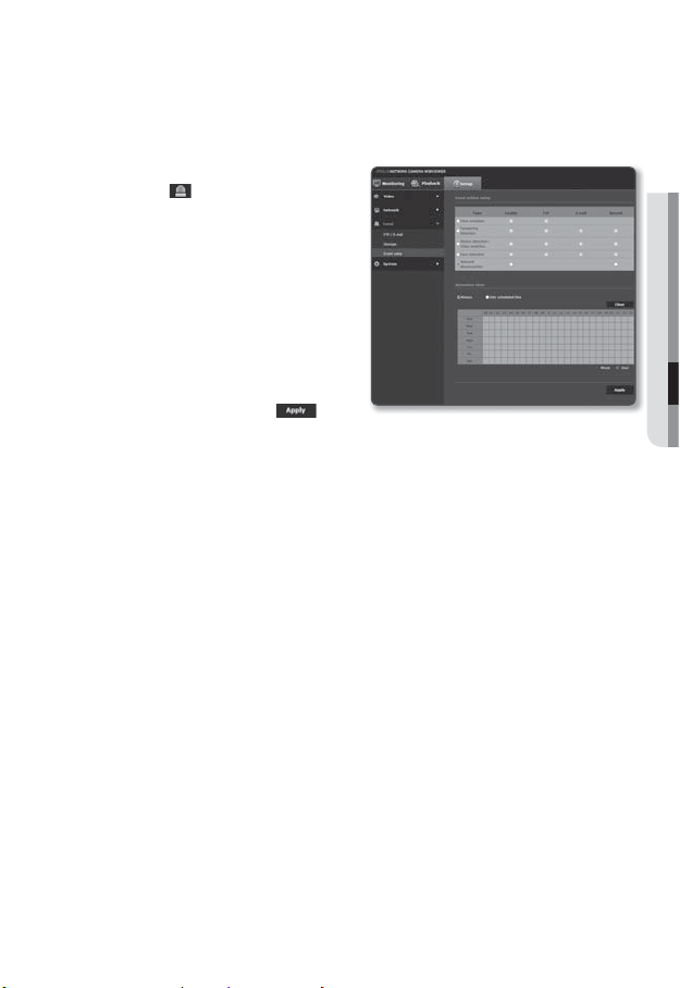
Network disconnection
You can receive and save events of a physically disconnected network.
1. From the Setup menu, select the
<Event (
2. Click <Event setup>.
3.
Select <Network disconnection> from
<Event action setup>.
4.
Set whether or not to <Enable>.
5. Specify the activation time and
activation condition.
6. When done, click [Apply (
)> tab.
For more information about <Activation
time> and <Action>, refer to “Tampering
detection”. (page
88)
)].
● SETUP SCREEN
English _97
Page 98
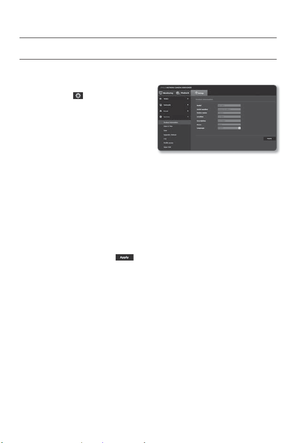
setup screen
SYSTEM SETUP
Product information
1. From the Setup menu, select the
<System (
2. Click <Product information>.
3. Check the camera information, or
provide details according to your
network environment.
• Model : Model name of the product.
• Serial number : Product serial
number.
• Device name : Provide a device name that will be displayed on the Live screen.
• Location : Specify the location where the camera is installed.
• Description : Provide detailed
information about the camera location.
• Memo : Provide an explanation about the camera for better understanding.
• Language : Select a preferred language for the Web Viewer OSD.
4. When done, click [Apply (
)> tab.
The default language is set to <English>.
M
)].
98_ setup screen
Page 99
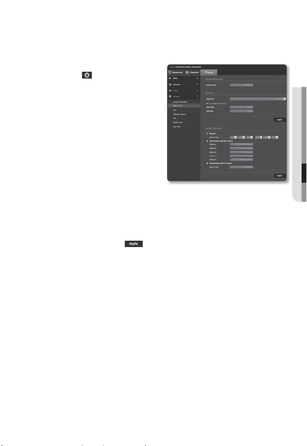
Date & Time
1. From the Setup menu, select the
<System ( )> tab.
2. Click <Date & Time>.
3. Specify the time and date that will be
applied to the camera.
• Current system time : Displays the
current time settings of your system.
• Timezone : Specify the local time
zone based on the GMT.
• Use daylight saving time :
If checked, the time will be set one
hour before the local time zone for
the specified time period.
This option will be displayed only in
areas where DST is applied.
• System time setup : Specify the time and date that will be applied to your system.
- Manual : Specify the time manually.
- Synchronize with NTP server : Sync with the time of the specified server address.
- Synchronize with PC viewer : Sets to the time of the computer connected.
4. When done, click [Apply (
If you select the <Synchronize with PC viewer>, the standard timezone should be set the same
J
as the current timezone in PC.
)].
● SETUP SCREEN
English _99
Page 100
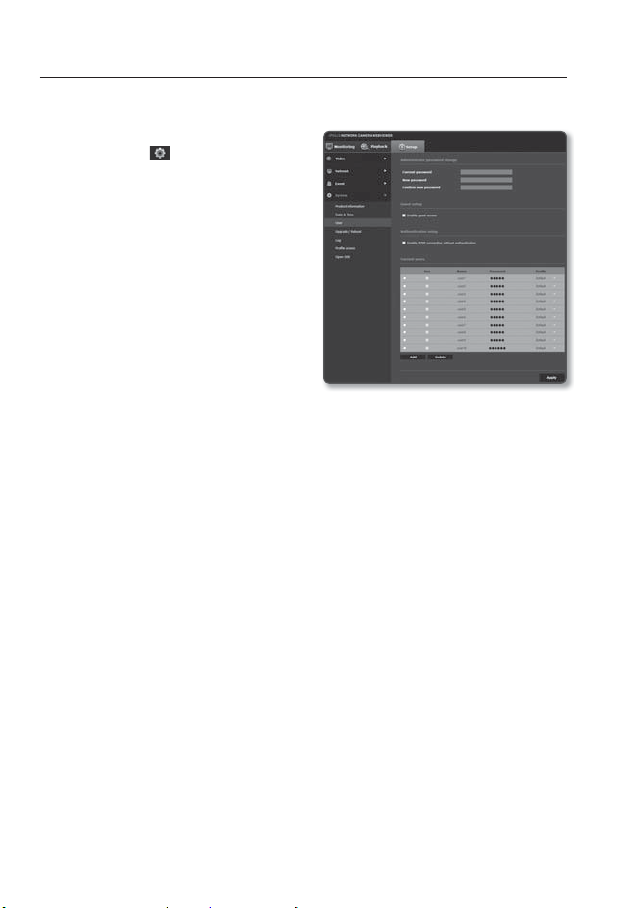
setup screen
User
1. From the Setup menu, select the
<System ( )> tab.
2. Click <User>.
3. Provide the necessary user information.
• Administrator password change :
Change the password for the
administrator.
The default password is vulnerable to
J
security threats. You should change it.
It is recommended to change your
password once every three months.
The password length and limits are
shown as follows.
A combination of at least two types of upper case, lower case, numeric, and special
-
characters: 8 to 15 characters.
Should be different from the ID.
-
Cannot repeat the same letter, number of special characters more than three times.
-
Cannot use three consecutive letters (e.g. abc, 123, 321, or ascii code values in the
-
sequential increasing or decreasing order)
Special characters that are allowed. : ~`!@#$%^*()_-+=|{}[].?/
-
After the factory setting, the admin password is set to 4321 and the user accounts are
-
user 1 through user 10 and with the passwords, user1 through user10.
When you access the camera web page for the first time or access it after the initialization,
-
you will be moved to the admin password setting menu.
In this menu, you need to login again with the new password before using the camera web
-
page menus.
100_ setup screen
 Loading...