

Page 1

NETWORK CAMERA
User Manual
SNP-L6233/SNP-L6233H
Page 2

Network Camera
User Manual
Copyright
©201
6 Hanwha Techw in Co., Ltd. Al l rights re served.
Trad em ark
Each of trad emarks herein is re gistered. The nam e of this product an d other trademark s mentioned in thi s manual are
the registe red trademark of th eir respective c ompany.
Restriction
Copyrigh t of this document is r eserved. Unde r no circumstanc es, this document s hall be reproduce d, distributed or
changed, pa rtially or wholl y, without formal au thorization.
Disclaimer
Samsung mak es the best to verif y the integrit y and correctne ss of the content s in this document, bu t no formal
guarantee s hall be provided. U se of this document a nd the subsequent r esults shall be ent irely on the user’s ow n
responsib ility. Samsung res erves the right t o change the conten ts of this documen t without prior no tice.
Design an d specificat ions are subjec t to change wit hout prior not ice.
The initi al administra tor ID is “admin” a nd the passwor d should be set wh en logging in for t he first time .
Please ch ange your pass word every thr ee months to sa fely protect p ersonal inf ormation and t o prevent
the damage o f the informat ion theft.
Please, t ake note that it ’s a user’s respo nsibility fo r the securit y and any other pr oblems cause d by
mismanag ing a password .
Page 3
overview
IMPORTANT SAFETY INSTRUCTIONS
1. Read these instructions.
2. Keep these instructions.
3. Heed all warnings.
4. Follow all instructions.
5. Do not use this apparatus near water.
6. Clean only with dry cloth.
7. Do not block any ventilation openings, Install in accordance with the manufacturer’s
instructions.
8. Do not install near any heat sources such as radiators, heat registers, stoves, or other
apparatus (including amplifiers) that produce heat.
9. Do not defeat the safety purpose of the polarized or grounding-type plug. A polarized
plug has two blades with one wider than the other. A grounding type plug has two
blades and a third grounding prong. The wide blade or the third prong are provided for
your safety. If the provided plug does not fit into your outlet, consult an electrician for
replacement of the obsolete outlet.
10. Protect the power cord from being walked on or pinched particularly at plugs,
convenience receptacles, and the point where they exit from the apparatus.
11. Only use attachments/ accessories specified by the manufacturer.
12. Use only with the cart, stand, tripod, bracket, or table specified by
the manufacturer, or sold with the apparatus. When a cart is used,
use caution when moving the cart/apparatus combination to avoid
injury from tip-over.
13. Unplug this apparatus during lighting storms or when unused for
long periods of time.
14. Refer all servicing to qualified service personnel. Servicing is required when the
apparatus has been damaged in any way, such as power-supply cord or plug is
damaged, liquid has been spilled or objects have fallen into the apparatus, the apparatus
has been exposed to rain or moisture, does not operate normally, or has been dropped.
15. This product is intended to be supplied by Power Unit marked “Class 2” or “LPS” and
rated 24 Vac(50 or 60 Hz), min. 1.0 A. (SNP-
16. This product is intended to be supplied by Power Unit marked “Class 2” or “LPS” and
rated 24 Vac(50 or 60 Hz), min. 2.9 A. (SNP-
L6233)
L6233H)
● OVERVIEW
English _3
Page 4
overview
WARNING
TO REDUCE THE RISK OF FIRE OR ELECTRIC SHOCK, DO NOT EXPOSE
THIS PRODUCT TO RAIN OR MOISTURE. DO NOT INSERT ANY METALLIC
OBJECT THROUGH THE VENTILATION GRILLS OR OTHER OPENNINGS
ON THE EQUIPMENT.
Apparatus shall not be exposed to dripping or splashing and that no objects
filled with liquids, such as vases, shall be placed on the apparatus.
To prevent injury, this apparatus must be securely attached to the Wall/ceiling
in accordance with the installation instructions.
CAUTION
CAUTION
RISK OF ELECTRIC SHOCK.
DO NOT OPEN
CAUTION
REFER SERVICING TO QUALIFIED SERVICE PERSONNEL.
: TO REDUCE THE RISK OF ELECTRIC SHOCK.
DO NOT REMOVE COVER (OR BACK).
NO USER SERVICEABLE PARTS INSIDE.
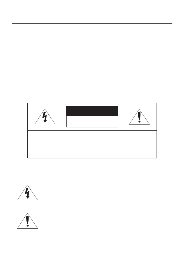
EXPLANATION OF GRAPHICAL SYMBOLS
The lightning flash with arrowhead symbol, within an
equilateral triangle, is intended to alert the user to the
presence of “dangerous voltage” within the product’s
enclosure that may be of sufficient magnitude to constitute a
risk of electric shock to persons.
The exclamation point within an equilateral triangle is intended
to alert the user to the presence of important operating
and maintenance (servicing) instructions in the literature
accompanying the product.
4_ overview
Page 5

Battery
Batteries(battery pack or batteries installed) shall not be exposed to excessive
heat such as sunshine, fire or the like.
CAUTION
Risk of explosion if battery is replaced by an incorrect type.
Dispose of used batteries according to the instructions.
These servicing instructions are for use by qualified service personnel only.
To reduce the risk of electric shock do not perform any servicing other than
that contained in the operating instructions unless you are qualified to do so.
The CVBS out terminal of the product is provided for easier installation, and is
not recommended for monitoring purposes.
Please use the input power with just one camera and other devices must not
be connected.
The ITE is to be connected only to PoE networks without routing to the
outside plant.
● OVERVIEW
English _5
Page 6

overview
Please read the following recommend safety precautions carefully.
Do not place this apparatus on an uneven surface.
Do not place this apparatus near conductive material.
Do not attempt to service this apparatus yourself.
Do not install near any magnetic sources.
Do not block any ventilation openings.
Do not place heavy items on the product.
Do not expose the camera to radioactivity.
User’s Manual is a guidance book for how to use the products.
The meaning of the symbols are shown below.
Reference : In case of providing information for helping of product’s usages
Notice : If there’s any possibility to occur any damages for the goods and
human caused by not following the instruction
Please read this manual for the safety before using of goods and keep it in
the safe place.
6_ overview
Page 7

CONTENTS
OVERVIEW
3
INSTALLATION &
CONNECTION
21
NETWORK CONNECTION
AND SETUP
40
3 Important Safety Instructions
9 Product Features
10 Recomended PC Specifications
11 Recomended SD/SDHC/SDXC
Memory Card Specifications
11 NAS recommended specs
12 What’s Included
14 At a Glance (SNP17 At a Glance (SNP-L6233H)
22 Connecting with other Device
25 Installation
37 Inserting/Removing a SD Memory
Card
39 Memory Card Information
(Not Included)
40 Connecting the Camera Directly
to Local Area Networking
41 Connecting the Camera Directly
to a DHCP Based DSL/Cable
Modem
42 Connecting the Camera Directly
to a PPPoE Modem
43 Connecting the Camera to a
Broadband Router with the
PPPoE/Cable Modem
44 Buttons used in IP Installer
45 Static IP Setup
49 Dynamic IP Setup
50
Port Range Forward (Port Mapping)
Setup
52 Connecting to the Camera from a
Shared Local PC
52 Connecting to the Camera from a
Remote PC via the Internet
L6233)
● OVERVIEW
English _7
Page 8

overview
WEB VIEWER
53
SETUP SCREEN
70
APPENDIX
141
53 Connecting to the Camera
54 Password setting
55 Login
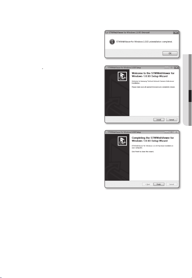
56 Installing STW WebViewer Plugin
58 Using the Live Screen
63 Playing the recorded video
70 Setup
70 Basic Setup
80 PTZ setup
90 Video & Audio setup
103 Network Setup
112 Event Setup
118 NAS (Network Attached Storage)
guide
135 System Setup
140 Viewing profile information
141 DIP Switch Setting
143 Camera Wiring
144 Specification
149 Product Overview
151 Troubleshooting
153 Open Source Announcement
8_ overview
Page 9

PRODUCT FEATURES
• Full HD Video Quality
• Multi-Streaming
This network camera can display videos in different resolutions and qualities
simultaneously using different CODECs.
• Web Browser-based Monitoring
Using the Internet web browser to display the image in a local network environment.
• Alarm
If an event occurs, the camera sends the relevant videos to the e-mail address or the FTP
server registered by the user, saves them in an SD card or NAS, or sends the signal to the
alarm output terminal.
• Tampering Detection
Detects tempering attempts on video monitoring.
• Motion Detection
Detects motion from the camera’s video input.
• Intelligent Video Analysis
Analyzes video to detect logical events of specified conditions from the camera’s video
input.
• Face Detection
Detects faces from the camera’s video input.
• Audio Detection
Detects sound louder than a certain level specified by user.
• Auto Detection of Disconnected Network
Detects network disconnection before triggering an event.
• ONVIF Compliance
This product supports ONVIF Profile-S.
For more information, refer to www.onvif.org.
● OVERVIEW
English _9
Page 10

overview
RECOMENDED PC SPECIFICATIONS
• CPU : Intel Core 2 Duo 2.6 GHz or higher (for using 1920x1080 30 fps)
Web Plug-in is optimized to SSE 4.1 Instruction Set.
• Resolution : 1280X1024 pixels or higher (32 bit color)
• RAM : 2GB or higher
• Supported OS : Windows XP / VISTA / 7 /
• Supported Browser : Microsoft Internet Explorer (Ver. 8~11),
Mozilla Firefox (Ver. 9~19), Google Chrome (Ver. 15~
Apple Safari (Ver. 6.0.2(Mac OS X 10.8, 10.7 only), 5.1.7) *Mac OS X Only
Windows 8 is supported only in the Desktop mode.
Neither a beta test version unlike the version released in the company website nor the developer version will
be supported.
It is recommended to connect to IPv6 in Windows 7.
The camera does not support Internet Explorer Compatability View settings.
For Mac OS X, only the Safari browser is supported.
• Video Memory : 256MB or higher
If the driver of the video graphic adapter is not installed properly or is not the latest version, the
J
video may not be played properly.
For a multi-monitoring system involving at least 2 monitors, the playback performance can be
deteriorated depending on the system.
It is advisable to use Intel Core 2 Duo 2.93GHz or higher in a multi-browser environment.
8, MAC OS X 10.7
25),
10_ overview
Page 11

RECOMENDED SD/SDHC/SDXC MEMORY CARD
SPECIFICATIONS
• Recommended capacity : 4GB ~ 64GB
• For your camera, we recommend you use a memory card from the following
manufacturers:
SD/SDHC/SDXC Memory Card : Sandisk, Transcend
• For the framerate below 30 fps, it is recommended to use the specification memory card
of Class 6 or high
er.
NAS RECOMMENDED SPECS
• Recommended capacity : 200GB or higher is recommended.
• Simultaneous access : One unit of NAS can accept a maximum of sixteen camera
accesses.
• For this camera, you are recommended to use a NAS with the following manufacturer’s
specs.
Recommended products Available sizes
Netgear NAS A maximum of 16 cameras can access simultaneously.
Synology NAS A maximum of 16 cameras can access simultaneously.
When you use Netgear’s NAS equipment, do not allocate the capacity for use.
J
If you use NAS equipment for purposes other than video saving, the number of accessible
cameras may be reduced.
● OVERVIEW
English _11
Page 12
overview
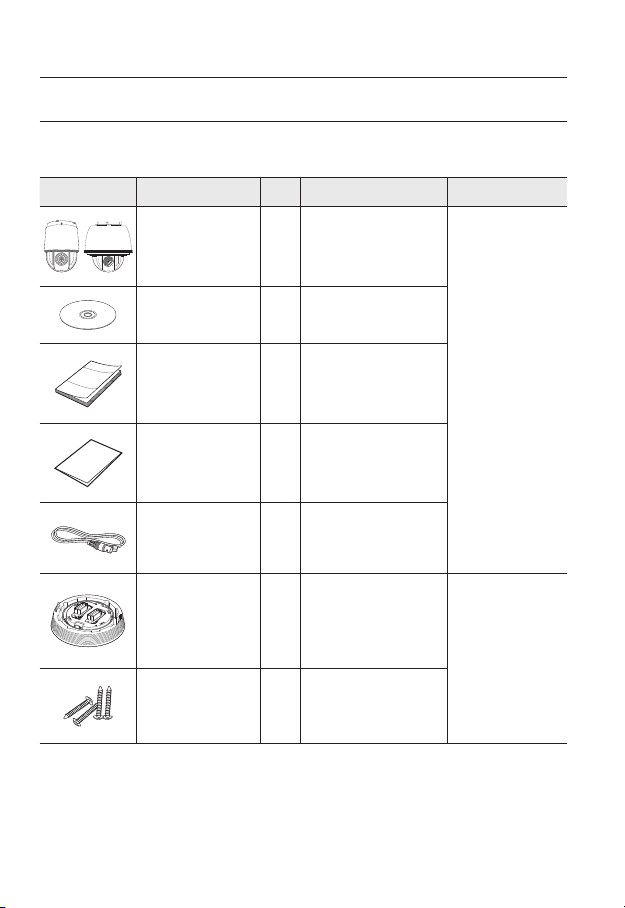
WHAT’S INCLUDED
Please check if your camera and accessories are all included in the product package.
(As for each sales country, accessories are not the same.)
Appearance Item Name
Camera 1
Quantity
Description Model Name
12_ overview
Instruction book,
Installer S/W CD
Quick Guide
(Optional)
Warranty card
(Optional)
Cable for the testing
monitor
Installation base 1
Tapping Screw 4
1
1
1
Used to test the camera
1
connection to a portable display
device
If installing it indoors or in a
ceiling housing
Used for installation on the
ceiling
SNP-
SNP-
SNP-
L6233 or
L6233H
L6233
Page 13
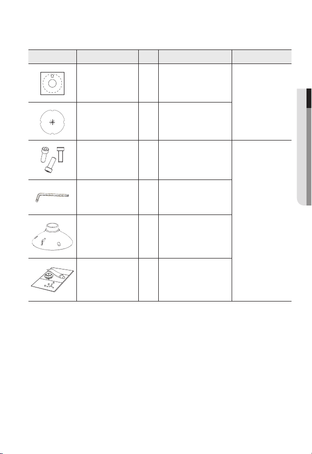
Appearance Item Name
Quantity
Description Model Name
Template 1 Product installation guide
Insulation Sheet 1
Hexagon screw 3
Use when installing the camera
at highly humid place
Used for attaching the
installation base to the camera
Used for fixing the installation
L Wrench 1
base after attaching it to the
camera
Installation base 1 Bracket for mounting outdoors
Waterproofing accessory 1
Install and use where there is
high humidity.
SNP-
SNP-
● OVERVIEW
L6233
L6233H
English _13
Page 14
overview
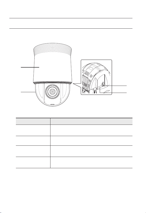
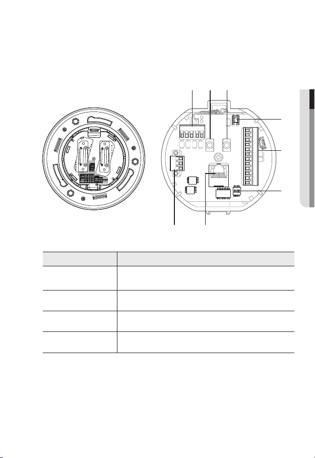
AT A GLANCE (SNP-L6233)
Appearance
Inside
b
Item Description
Main unit
Dome Cover Dome cover for the lens and unit protection.
b
Reset Button
c
SD Memory Card
Compartment
Protects the internal PTZ mechanism from the direct sunlight or external
impact.
Pressing and holding this button for about 5 seconds will reset all camera
settings to the factory default.
Compartment for the SD memory card.
c
14_ overview
Page 15
Bottom View of Installation
Base
Inner View of Installation Base
c
b
● OVERVIEW
ON
SW1
1
234
123
UART
Termination
RS-422 ON
NOT Termination
Termination
RS-485 OFF
Switch No.4 : Not used Pin
ON
OFF
OFFOFF
ON ON
AC- FG AC-
Item Description
Communications
Ports
Audio Input Port Used to connect the audio input cable.
b
Audio Output Port Used to connect the audio output cable.
c
Video Out Port Analog video output port. (for installation)
Used for RS-485/422 communications.
D+ D- TXD+ TXD- GND
AUDIO OUTAUDIO IN
2.NC
2.NO
2.COM
1.NO 1.NCIN1 IN2 GND IN3 IN4
1.COM
GND
English _15
Page 16

overview
Item Description
Alarm I/O Port Used to connect the alarm I/O cable.
Communications
Setup Switch
Network
Connections
Power Port Used to connect the power.
Set communication protocol (RS-486/422) and indicate whether to
terminate.
You can use a PoE+ or an Ethernet cable to connect this terminal to the
network.
16_ overview
Page 17
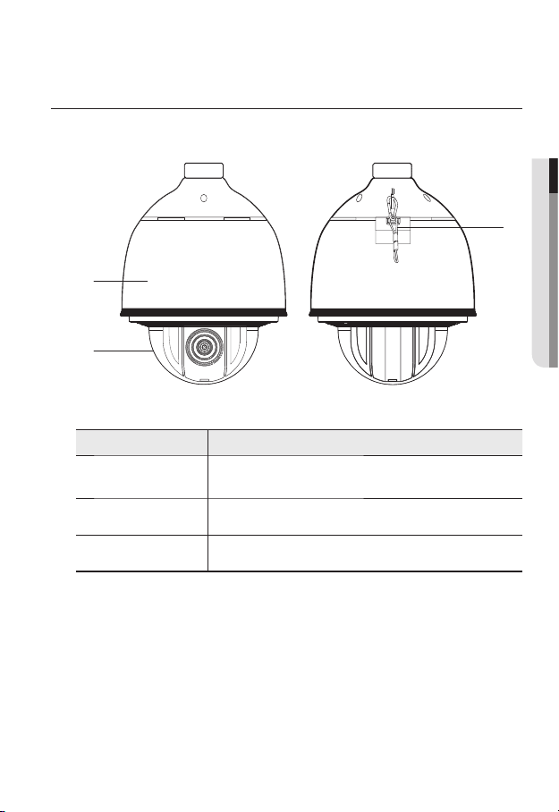
AT A GLANCE (SNP-L6233H)
Appearance
b
Item Description
Main unit
Dome Cover Dome cover for the lens and unit protection.
b
Safety Cable The cable prevents the product from dropping during installation.
c
Protects the internal PTZ mechanism from the direct sunlight, rain or
external impact.
● OVERVIEW
c
English _17
Page 18
overview
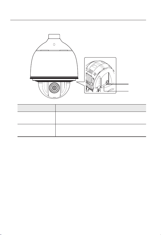
Inside
Item Description
Reset Button
SD Memory Card
b
Compartment
b
Pressing and holding this button for about 5 seconds will reset all camera
settings to the factory default.
Compartment for the SD memory card.
18_ overview
Page 19
Bottom View of Installation
Base
Inner View of Installation Base
c
b
● OVERVIEW
AC- FG AC-
Item Description
Communications
Ports
Audio Input Port Used to connect the audio input cable.
b
Audio Output Port Used to connect the audio output cable.
c
Video Out Port Analog video output port. (for installation)
Used for RS-485/422 communications.
D+ D- TXD+ TXD-GND
AUDIO OUTAUDIO IN
2.NC
2.NO
2.COM
1.NO 1.NCIN1 IN2 GND IN3 IN4
1.COM
GND
English _19
Page 20

overview
Item Description
Alarm I/O Port Used to connect the alarm I/O cable.
Communications
Setup Switch
Network
Connections
Power Port Used to connect the power.
Set communication protocol (RS-486/422) and indicate whether to
terminate.
You can use a PoE+ or an Ethernet cable to connect this terminal to the
network.
20_ overview
Page 21
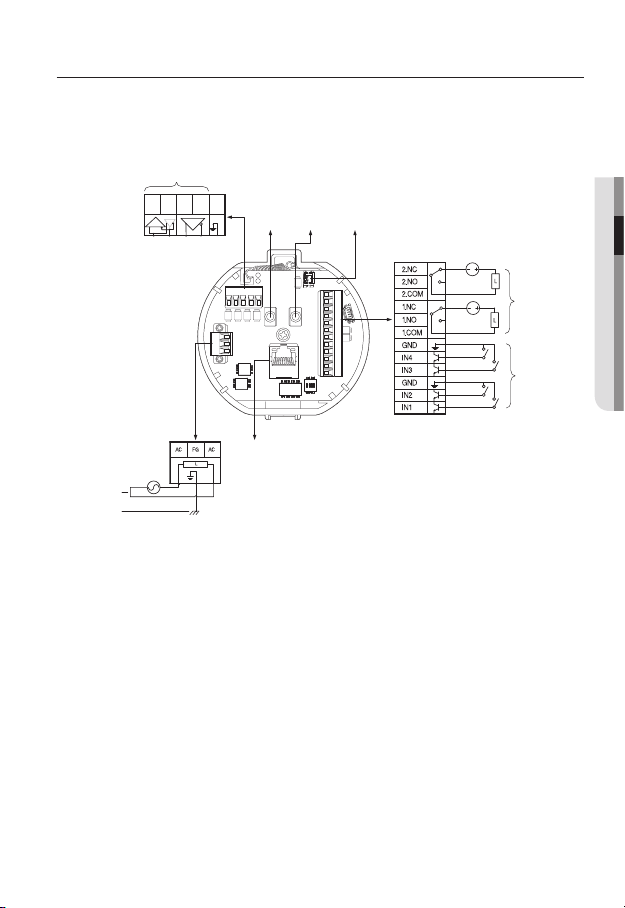
installation & connection
Camera Wiring Interface Board
For the camera wiring, please refer to the picture below.
Refer to Control Signal
Connection Diagram
D+ D- TXD+ TXD- GND
Communications
(SNP-L6233 : AC 24V, 2.5A/
SNP-L6233H : AC 24V, 3A)
Power Input
Ground
Select Normal Open in the setup menu.
J
Select Normal Close from the Setup menu.
The maximum capacity of the alarm output terminal is 30V DC/2A, 125V AC/0.5A and 250V
AC/0.25A.
When connecting alarm input and output cables, be sure to connect one cable to each
terminal respectively.
To connect products over the camera’s capacity, please use an additional relay device.
If power and GND cables are connected inappropriately to the NC/NO or COM port, a fire or
breakdown of equipment may occur.
Audio INAudio
D+ D- TXD+ TXD-GND
AC- FG AC-
Power
Supply
ETHERNET
The sensor input is activated during a short for contact type, or when it is at “Low” level for
-
the active type.
The sensor input is activated when open for the contact type or when in high impedance
-
state (open collector) for the active type.
Video
Output
OUT
Alarm
2.NC
2.NO
AUDIO OUTAUDIO IN
2.COM
1.NO 1.NCIN1 IN2 GND IN3 IN4
1.COM
GND
● INSTALLATION & CONNECTION
Alarm output
Alarm Input
English _21
Page 22
installation & connection
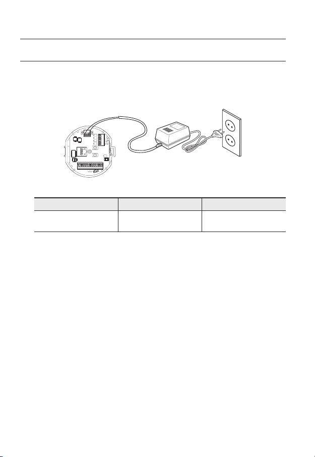
CONNECTING WITH OTHER DEVICE
Preparing Adapter and Cable
Connect the camera to the power adaptor. Then, plug the power cord of the adaptor to the wall
J
outlet.
AC- FGAC-
D+ D-TXD+ TXD-GND
AUDIO OUTAUDIO IN
GND
1.COM
1.NO 1.NCIN1 IN2 GND IN3 IN4
2.COM
2.NO
2.NC
Check out the rated voltage and current before making connections.
Rated Power Allowable Input Voltage Current Consumption
AC 24V AC 22V ~ 26V
If applied with both PoE+ and AC 24V power supplies, the device is powered from the first
J
engaged supply.
It is preferred to use single power supply of either one of PoE+ and AC 24V.
-
If connected to a switch device that provides PoE+ power, you don’t need to apply a power source
of AC 24V supply.
Make sure the PoE device suffices PoE+ (IEEE 802.3at) specifications.
If your device is connected to the switch with the standard of PoE (IEEE 802.3af), then go to
-
the switch setup menu to “deactivate PoE”.
For further information on switch device, refer to the manufacturer’s manual.
It is recommended to use a cable that complies with the PoE+ spec.
-
If you use a PoE+ as a power, the boot time may vary depending on a switch model (by channel)
or a maker (as PoE+ connection time is included.).
L6233 : AC 24V, 2.5A/
(SNP-
L6233H : AC 24V, 3A)
SNP-
22_ installation & connection
Page 23

Electrical Resistance of Copper Wire at [20°C (68°F)]
Copper Wire Gauge (AWG) #24(0.22mm2) #22(0.33mm2) #20(0.52mm2) #18(0.83mm2)
Resistance (Ω/m) 0.078 0.050 0.030 0.018
Drop Voltage (V/m) 0.028 0.018 0.011 0.006
Recommended Distance (m) Less than 20 Less than 30 Less than 30 Less than 30
As shown in the table above, you may encounter a voltage-sag depending on the wire length.
If you use an excessively long wire for camera connection, the camera may not work properly.
Camera Operating Voltage: AC 24V±10%
-
Voltage drop measurements on the chart above may vary depending on the type and manufacture of
-
the copper cable.
Ethernet Connection
Connect the Ethernet cable to the local network or to the Internet.
● INSTALLATION & CONNECTION
English _23
Page 24
installation & connection
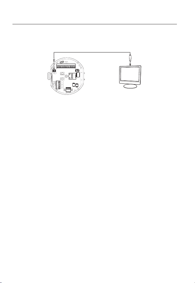
Connecting the installation monitor
Connect the cable to the camera’s rear video output terminal and the installation monitor’s
video input terminal.
GND
1.COM
1.NO 1.NCIN1 IN2 GND IN3 IN4
2.COM
2.NO
2.NC
AUDIO OUTAUDIO IN
D+ D-TXD+ TXD-GND
AC- FG AC-
The wiring varies depending on your monitor type and peripheral devices; please refer to the user manual
for each device.
Please make sure the monitor and camera are turned off when connecting them.
This product is a network camera that transfers video over a network; the video output terminal is
J
used to set the imaging range of the camera at installation.
Using the terminal for monitoring purposes may cause problems such as degradation in video
quality.
It is not suitable for 24-hour monitoring using professional CRT monitors or TFT/LCD portable
monitors.
Use the network transfer screen for 24-hour monitoring and storage.
Monitor
24_ installation & connection
Page 25
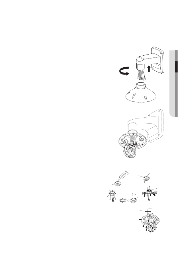
INSTALLATION
Preparing & Installing Camera Bracket
For installation guidelines for brackets and housings, refer to the installation manual that is
enclosed with the bracket or housing.
Available Bracket Models
Model Item SNP-L6233 SNP-L6233H
SHP-3701H Outdoor Housing
-SHP-3701F Ceiling-mount Housing
SBP-301HM3 Hanging Mount
SBP-300WM1
SBP-300WM
SBP-300CM Ceiling Mount
SBP-300LM Parapet Mount
SBP-300KM Corner Mount
SBP-300PM Pole Mount
See “Optional Accessories for Installation” for the appearance of each bracket (unbundled).
M
(page 33)
Wall Mount
Yes
Yes
● INSTALLATION & CONNECTION
English _25
Page 26
installation & connection
Installing by surface attachment
SNP-L6233H cannot be installed on the surface of a wall or ceiling.
M
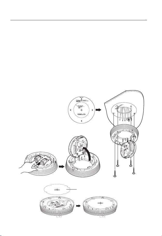
Attaching Template & Installing installation base
1. Attach the provided template on the ceiling. Based on the template, drill a 86mm
hole in the ceiling and arrange the wires through the hole.
2. Install installation base as shown.
3. Before installing the exposed bracket, open the hinged door at the bottom of the
bracket as shown in the picture. Hold the knob on the hinged door to open it.
In the case of installing the camera at highly humid place, install it on the ceiling after attaching
J
the enclosed insulation sheet on the back of install base.
Template
26_ installation & connection
Insulation Sheet
<Attaching insulatioin sheet>
Page 27
Connect Terminal Wires
1. Connect the cables to the terminal block on the
hinged door. Refer to “Camera Wiring Interface
Board”. (page 21)
2. Once the wiring is complete, close the hinged
door.
Do not connect the camera to a power outlet until the
J
installation is complete. Supplying power while the
installation is in progress may cause fire or damage the
product.
Connecting Camera Safety Cable and Attaching Camera
1. First, as shown in the left hand picture, pull out the safety cable from the base and
then hook it to the mount. The safety cable is coiled inside the base.
To attach the camera to the mount, refer to the alignment guide marks as shown in the picture.
2. Carefully attach the camera to the mount following the alignment guide marks as
shown in the picture.
Direction
Guides
Direction
Guides
Align the Direction
Guides
● INSTALLATION & CONNECTION
Make sure to hook the camera’s safety cable to the mount before proceeding. Otherwise you may
J
be exposed to serious injury caused by the camera falling.
English _27
Page 28
installation & connection
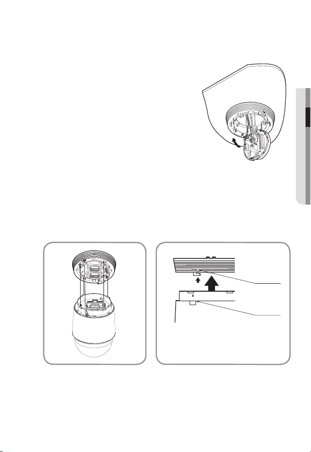
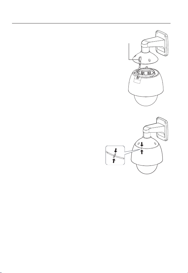
- To attach or detach the camera, refer to the picture.
• Attaching the Camera : Push up the camera unit and rotate it clockwise until
it cannot be rotated anymore, as shown in the figure. After rotation, fasten the
screws assembled to the install base.
< To Attach the Camera >
• Detaching the Camera : Unfasten the screws as shown in the figure, push in the
hook, and rotate it counterclockwise.
(The screws are not completely disassembled.)
When the hook does not rotate any more, pull down the camera unit and
separate it.
28_ installation & connection
< To Detach the Camera >
Page 29
Installing by wall mount
Fix the installation base with the bracket
1. Fix the base with the bracket by turning it
clockwise.
2. As shown in the picture below, gently press and
lift up the handle of the hinged door on the bottom
of the installation base. Please refer to the “Camera
Wiring Interface Board” on page 21, connect the
wires.
Do not connect the camera to a power outlet until the
J
installation is complete. Supplying power while the
installation is in progress may cause fire or damage the
product.
Check cable connection method and install.
M
Note that BUSHINGs are provided for outdoor
installations where exposed to a moisture
condition through the PIPE or MOUNT, install
the HOUSING using the BUSHING to prevent
moisture entering.
Apply grease of proper dose on the BUSHING
-
before assembling, and run cables through
each hole of the bushings. Use PINS to stop up empty holes
having no cable running.
Assemble the BUSHING to the top side of HOUSING’s inside
-
as shown in the diagram below. At the moment, apply pressure
evenly on the BUSHING to secure it tightly to the HOUSING as
shown in the diagram.
● INSTALLATION & CONNECTION
POE+ 또는 이더넷 케이블
POE+ or Ethernet cable
POWER
POWER (AC24V)
(AC24V)
기타 케이블
인터페이스
INTERFACE
핀
PIN
BUSH
BUSH
하우징
HOUSING OR
또는 마운트
MOUNT
ETC CABLE
BUSH
BUSH
하우징
HOUSING
BUSH
BUSH
BUSH
BUSH
BUSH
BUSH
English _29
Page 30
installation & connection
3. Connect the camera safety wire to the installation base.
Safety Cable
4. Assemble Camera and Installation Base
Assemble the installation base and camera
by matching the installation direction guides.
30_ installation & connection
Page 31
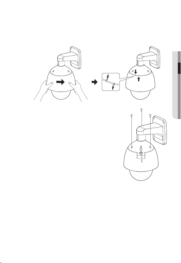
5. Attach Camera
Rotate the mounted camera unit clockwise so that the reference indicators of top
and bottom are as shown in the image on the right.
6. Secure Camera and Installation Base
As shown in the picture below, secure
the installation base and camera using 3
hexagon screws.
● INSTALLATION & CONNECTION
English _31
Page 32

installation & connection
Notes for Waterproofing
This product is an indoor unit. If it is installed outdoors, use the outdoor housing to make it
waterproof.
Installing the unit on the wall by combining the outdoor housing and wall
mount
1. Install the wall mount on the vertical wall.
If the mount is installed on an inclined
wall, moisture can penetrate inside the
outdoor housing through the external
cable.
2. Wrap the screw part of the housing with
a sufficient amount of Teflon tape for
assembly.
3. When separating the dome cover and
fastening it to the housing frame, make
sure that the gasket is not loosened to
separate from the dome cover.
4. Install the wall mount adapter for
waterproofing, and apply the silicon
sealant between and around the wall and
wall mount for sealing.
Take particular caution to ensure that there
J
is proper sealing if the installed side is not
flat.
Silicon
sealant
Wall mount
Screw
unit
Concrete wall
Teflon tape
Dome gasket
32_ installation & connection
Page 33

Installing on the wall by combining the outdoor housing and ceiling mount
adapter
1. Wrap the screw part of the housing
with a sufficient amount of Teflon tape
for assembly.
2. When separating the dome cover and
fastening it to the housing frame, make
sure that the gasket is not loosened to
separate from the dome cover.
3. Install the ceiling mount adapter for
waterproofing, and apply the silicon
sealant between and around the wall
and ceiling mount for sealing.
Take particular caution to ensure that
J
there is proper sealing if the installed side
is not flat.
Ceiling mount
adapter
Ceiling board
Screw
unit
Concrete ceiling
Silicon
sealant
Teflon tape
Dome gasket
Optional Accessories for Installation
For your easier installation, you can purchase appropriate optional accessories available.
1. If installing the camera on the wall
• Wall mount (SBP-300WM1)
● INSTALLATION & CONNECTION
English _33
Page 34

installation & connection
• Wall mount (SBP-300WM)
2. If installing the camera on the ceiling
• Ceiling Mount (SBP-300CM)
3. If installing the wall mount (SBP-300WM/SBP-300WM1) on an at least 80mm-long
cylinder
• Pole Mount (SBP-300PM)
34_ installation & connection
Page 35

4. If installing the wall mount (SBP-300WM/SBP-300WM1) on a corner of the wall
• Corner Mount (SBP-300KM)
5. If installing on a building rooftop
• Parapet Mount (SBP-300LM)
● INSTALLATION & CONNECTION
6. If installing SNP-
L6233 outdoors
• Outdoor Housing (SHP-3701H)
English _35
Page 36

installation & connection
7. If installing SNP-L6233 on a ceiling as built-in component
• Flush-Mount Indoor Housing for PTZ Dome Camera
(SHP-3701F)
8. If installing SNP-
• Hanging Mount (SBP-301HM3)
36_ installation & connection
L6233 in the wall mount or ceiling mount
Page 37

INSERTING/REMOVING A SD MEMORY CARD
Disconnect the power cable from the camera before inserting the SD memory card.
J
Inserting a SD Memory Card
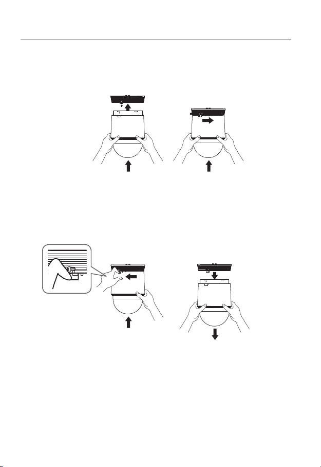
1. Turn dome cover counterclockwise to open.
(SNP-L6233)
Using the screw driver, loosen 3 screws by turning them
counterclockwise and separate the dome cover.
L6233H)
(SNP-
● INSTALLATION & CONNECTION
English _37
Page 38

installation & connection
2. Push the SD memory card in the direction of the
arrow shown in the diagram.
Do not insert the SD memory card while it’s upside down
J
by force. Otherwise, it may damage the SD memory card.
Removing a SD Memory Card
Gently press down on the exposed end of the memory
card as shown in the diagram to eject the memory card
from the slot.
Pressing too hard on the SD memory card can cause
J
the card to shoot out uncontrollably from the slot when
released.
To turn off the camera or remove the SD memory card,
set the card to <Off> in <Storage> menu and press the
[Apply (
If you turn off the camera or remove the SD memory card
that contains data from the product, the data may be lost or damaged.
)] button. (page 114)
38_ installation & connection
Page 39

MEMORY CARD INFORMATION (NOT INCLUDED)
What is a memory card?
The memory card is an external data storage device that has been developed to offer an
entirely new way to record and share video, audio, and text data using digital devices.
Selecting a memory card that’s suitable for you
Your camera supports SD/SDHC/SDXC memory cards.
You may, however, experience compatibility issues depending on the model and make of
the memory card.
For your camera, we recommend you use a memory card from the following
manufacturers:
SD/SDHC/SDXC Memory Card : Sandisk, Transcend
Memory cards of 4GB ~ 64GB is recommended for using with this camera.
Playback performance can be affected depending on the speed of memory card, so use
the high-speed memory card.
For the framerate below 30 fps, it is recommended to use the specification memory card of
Class 6 or high
Memory Card Use
SD/SDHC/SDXC memory cards feature a switch that disables writing data on to the media.
Having this switch to the Lock position will prevent accidental deletion of data stored in the
memory card but at the same time will also prevent you from writing data on to the media.
er.
● INSTALLATION & CONNECTION
English _39
Page 40

network connection and setup
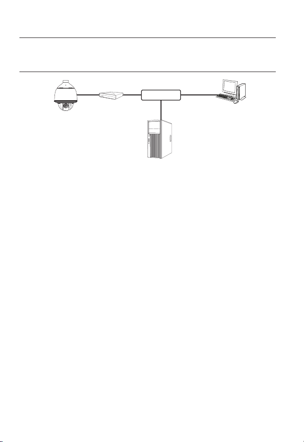
You can set up the network settings according to your network configurations.
CONNECTING THE CAMERA DIRECTLY TO LOCAL AREA
NETWORKING
Connecting to the camera from a local PC in the LAN
1. Launch an Internet browser on the local PC.
2. Enter the IP address of the camera in the address bar of the browser.
Camera
Camera
Local PC
<Local Network>
A remote PC in an external Internet out of the LAN network may not be able to connect to the
M
camera installed in the intranet if the port-forwarding is not properly set or a firewall is set.
In this case, to resolve the problem, contact your network administrator.
In the IP installer, you can use the initial password, “4321” to set IP Address, Subnet Mask,
Gateway, HTTP Port, VNP Port, IP type. After changing the network interface, for better security,
access the web viewer and change the password.
By factory default, the IP address will be assigned from the DHCP server automatically.
If there is no DHCP server available, the IP address will be set to 192.168.1.100.
To change the IP address, use the IP Installer.
For further details on IP Installer use, refer to “Static IP Setup”. (Page 45)
40_ network connection and setup
Switch
Firewall
INTERNET
External Remote PC
DDNS Server
(Data Center, KOREA)
Page 41

CONNECTING THE CAMERA DIRECTLY TO A DHCP
BASED DSL/CABLE MODEM
INTERNET
DDNS Server
(Data Center, KOREA)
External Remote PC
Camera
DSL/Cable
Modem
1. Connect the user PC directly with the network camera.
2. Run the IP Installer and change the IP address of the camera so that you can use
the web browser on your desktop to connect to the Internet.
3. Use the Internet browser to connect to the web viewer.
4. Move to [Setup] page.
5. Move to [Network] – [DDNS] and configure the DDNS settings.
6. Move to [Basic] – [IP & Port], and set the IP type to [DHCP].
7. Connect the camera, which was removed from your PC, directly to the modem.
8. Restart the camera.
For configuring the DDNS settings, refer to “DDNS”. (page 103)
M
For registering the DDNS settings, refer to “Registering with DDNS”. (page 104)
Refer to “IP & Port” for how to setup IP. (page 78)
●
NETWORK CONNECTION AND SETUP
English _41
Page 42
network connection and setup
CONNECTING THE CAMERA DIRECTLY TO A PPPoE
MODEM
PPPoE Modem
Camera
1. Connect the user PC directly with the network camera.
2. Run the IP Installer and change the IP address of the camera so that you can use
the web browser on your desktop to connect to the Internet.
3. Use the Internet browser to connect to the web viewer.
4. Move to [Setup] page.
5. Move to [Network] – [DDNS] and configure the DDNS settings.
6. Move to [Basic] – [IP & Port] Setup Page, set the IP type to [PPPoE], and enter the
network service’s ID and password.
7. Connect the camera, which was removed from your PC, directly to the modem.
8. Restart the camera.
For configuring the DDNS settings, refer to “DDNS”. (page 103)
M
For registering the DDNS settings, refer to “Registering with DDNS”. (page 104)
Refer to “IP & Port” for how to setup IP. (page 78)
INTERNET
DDNS Server
(Data Center, KOREA)
External Remote PC
42_ network connection and setup
Page 43

CONNECTING THE CAMERA TO A BROADBAND ROUTER
WITH THE PPPoE/CABLE MODEM
This is for a small network environment such as homes, SOHO and ordinary shops.
Camera
●
NETWORK CONNECTION AND SETUP
INTERNET
PPPoE or
Cable Modem
DDNS Server
(Data Center, KOREA)
External Remote
PC
Camera
Local PC
Broadband
Router
PPPoE or
Cable Modem
Configuring the network settings of the local PC connected to a
Broadband Router
Configuring the network settings of the local PC connected to a Broadband Router, follow
the instructions below.
• Select : <Network> <Properties> <Local Area Connection> <General>
<Properties> <Internet Protocol (TCP/IP)> <Properties> <Obtain an
IP address automatically> or <Use the following IP address>.
• Follow the instructions below if you select <Use the following IP address>:
ex1) If the address (LAN IP) of the Broadband Router is 192.168.1.1
IP address : 192.168.1.100
Subnet Mask : 255.255.255.0
Default Gateway : 192.168.1.1
ex2) If the address (LAN IP) of the Broadband Router is 192.168.0.1
IP address : 192.168.0.100
Subnet Mask : 255.255.255.0
Default Gateway : 192.168.0.1
ex3) If the address (LAN IP) of the Broadband Router is 192.168.xxx.1
IP address : 192.168.xxx.100
Subnet Mask : 255.255.255.0
Default Gateway : 192.168.xxx.1
For the address of the Broadband Router, refer to the product’s documentation.
M
For more information about port forwarding of the broadband router, refer to “Port Range
Forward (Port Mapping) Setup”. (Page 50)
English _43
Page 44

network connection and setup
BUTTONS USED IN IP INSTALLER
b c
m
Item Description
Device Name
Alias This function is not currently implemented.
b
Mode
c
MAC(Ethernet)
Address
IP Address
Protocol
Model name of the connected camera.
Click the column to sort the list by model name.
However, search will be stopped if clicked during the search.
Displays either <Static>, <Dynamic> or <PPPoE> for the current network
connection status.
Ethernet address for the connected camera.
Click the column to sort the list by Ethernet address.
However, search will be stopped if clicked during the search.
IP address.
Click the column to sort the list by IP address.
However, search will be stopped if clicked during the search.
Network setting for the camera.
The factory default is “IPv4”.
Cameras with the IPv6 setting will be displayed “IPv6”.
44_ network connection and setup
Page 45
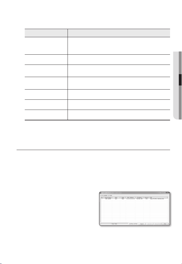
Item Description
URL
IPv4 Scans for cameras with the IPv4 setting.
IPv6
Search
Auto Set The IP Installer automatically configures the network settings.
Manual Set You should configure the network settings manually.
Exit Exits the IP Installer program.
m
For the IP installer, use only the installer version provided in the installation CD or use the latest one if
M
available. You can download the latest version from the Samsung web site.
DDNS URL address enabling access from the external Internet.
However, this will be replaced with the <IP Address> of the camera if
DDNS registration has failed.
Scans for cameras with the IPv6 setting.
Activated in an IPv6 compliant environment only.
Scans for cameras that are currently connected to the network.
However, this button will be grayed out if neither IPv4 nor IPv6 is checked.
STATIC IP SETUP
Manual Network Setup
Run <IP Installer_v2.XX.exe> to display the camera search list.
At the initial startup, both [Auto Set] and [Manual Set] will be grayed out.
For cameras found with the IPv6 setting, these buttons will be grayed out as the cameras do not
M
support this function.
1. Select a camera in the search list.
Check the MAC address of the camera
on the camera’s label.
Both the [Auto Set] and [Manual Set]
buttons will be activated.
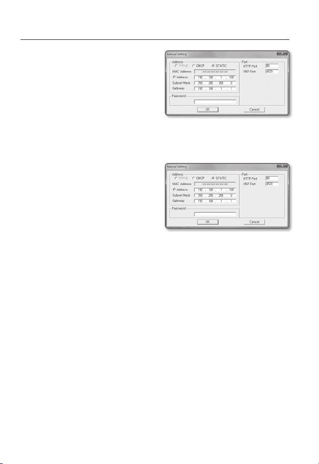
2. Click [Manual Set].
The Manual Setting dialog appears.
The default values of <IP Address>,
<Subnet Mask>, <Gateway>, <HTTP Port> and <VNP Port> of the camera will
be displayed.
●
NETWORK CONNECTION AND SETUP
English _45
Page 46
network connection and setup
3. In the <Address> pane, provide the
necessary information.
• MAC (Ethernet) Address : The MAC
address imprinted on the camera
label is automatically displayed and
requires no user setting.
You can configure the static IP settings
M
only if the DHCP checkbox is unchecked.
If not using a Broadband Router
For setting <IP Address>, <Subnet Mask>, and <Gateway>, contact your network administrator.
4. In the <Port> pane, provide necessary
information.
• HTTP Port : Used to access the
camera using the Internet browser,
defaulted to 80.
• VNP Port : Used to control the video
signal transfer, defaulted to 4520.
5. Enter the password.
Enter the password of “admin” account, which was used to access the camera.
For the security purposes, you are recommended to use a combination of numbers, alphabets
J
uppercase and lowercase and special characters for your password.
If you want to change the password, refer to “Administrator password change” of the user
setup. (page 75)
6. Click [OK].
Manual network setup will be completed.
46_ network connection and setup
Page 47
If using a Broadband Router
• IP Address : Enter an address falling in
the IP range provided by the Broadband
Router.
ex) 192.168.1.2~254,
192.168.0.2~254,
192.168.XXX.2~254
• Subnet Mask : The <Subnet Mask>
of the Broadband Router will be the
<Subnet Mask> of the camera.
• Gateway : The <Local IP Address> of
the Broadband Router will be the <Gateway> of the camera.
The settings may differ depending on the connected Broadband Router model.
M
For more information, refer to the user manual of the applicable router.
For more information about port forwarding of the broadband router, refer to “Port Range
Forward (Port Mapping) Setup”. (Page 50)
If the Broadband Router has more than one camera connected
Configure the IP related settings and the Port related settings distinctly with each other.
ex)
Category Camera #1 Camera #2
●
NETWORK CONNECTION AND SETUP
IP related settings
Port related settings
If the <HTTP Port> is set other than 80, you must provide the <Port> number in the address bar
M
of the Internet browser before you can access the camera.
ex) http://IP address : HTTP Port
IP Address
Subnet Mask
Gateway
HTTP Port
VNP Port
http://192.168.1.100:8080
192.168.1.100
255.255.255.0
192.168.1.1
8080
4520
192.168.1.101
255.255.255.0
192.168.1.1
8081
4521
English _47
Page 48

network connection and setup
Auto Network Setup
Run <IP Installer_v2.XX.exe> to display the camera search list.
At the initial startup, both [Auto Set] and [Manual Set] will be grayed out.
For cameras found with the IPv6 setting, these buttons will be grayed out as the cameras do not
M
support this function.
1. Select a camera in the search list.
Check the MAC address of the camera
on the camera’s label.
Both the [Auto Set] and [Manual Set]
buttons will be activated.
2. Click [Auto Set].
The Auto Setting dialog appears.
The <IP Address>, <Subnet Mask>,
and <Gateway> will be set automatically.
3. Enter the password.
Enter the password of “admin” account,
which was used to access the camera.
For the security purposes, you are
J
recommended to use a combination
of numbers, alphabets uppercase and
lowercase and special characters for your
password.
If you want to change the password, refer
to “Administrator password change” of
the user setup. (page 75)
4. Click [OK].
Auto network setup will be completed.
48_ network connection and setup
Page 49
DYNAMIC IP SETUP
Dynamic IP Environment Setup
• Example of the Dynamic IP environment
- If a Broadband Router, with cameras connected, is assigned an IP address by the
DHCP server
- If connecting the camera directly to modem using the DHCP protocols
- If IPs are assigned by the internal DHCP server via the LAN
Checking the Dynamic IP
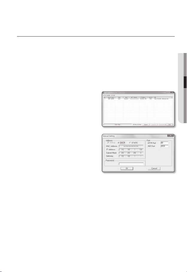
1. Run the IP Installer on the user’s local
computer.
Cameras allocated with <Dynamic IP>
address are shown in the list.
2. Select a camera from the search result.
3. Click the [Manual Set] button and
check the camera’s <Dynamic IP>
address.
If you uncheck <DHCP>, you can
change IP to <Static>.
●
NETWORK CONNECTION AND SETUP
English _49
Page 50

network connection and setup
PORT RANGE FORWARD (PORT MAPPING) SETUP
If you have installed a Broadband Router with a camera connected, you must set the port range
forwarding on the Broadband Router so that a remote PC can access the camera in it.
Manual Port Range Forwarding
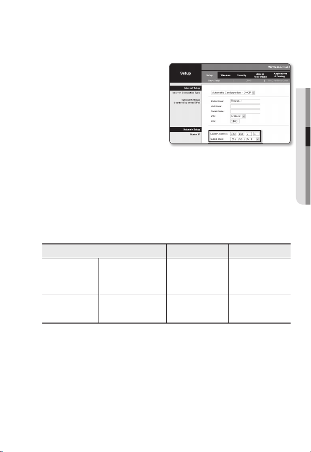
1. From the Setup menu of the Broadband
Router, select <Applications &
Gaming> - <Port Range Forward>.
For setting the port range forward for
a third-party Broadband Router, refer
to the user guide of that Broadband
Router.
2. Select <TCP> and <UDP Port>
for each connected camera to the
Broadband Router.
Each port number for the Broadband
Router should match that specified in
<Setup> - <Basic> - <IP & Port> from
the camera’s web viewer menu.
3. When done, click [Save Settings].
Your settings will be saved.
Above sample instructions are based on the CISCO’s Broadband Router.
M
The settings may differ depending on the connected Broadband Router model.
For more information, refer to the user manual of the applicable router.
50_ network connection and setup
Page 51

Setting up Port Range Forward for several network cameras
• You can set a rule of Port Forwarding on the Broadband Router device through its
configuration web page.
• A user can change each port using the camera setting screen.
When Camera1 and Camera2 are connected to a router :
●
NETWORK CONNECTION AND SETUP
User Internet
Start End Protocol IP Address
3000 3000 TCP/UDP 192.168.1.100
3001 3001 TCP/UDP 192.168.1.101
4520 4520 TCP/UDP 192.168.1.100
4521 4521 TCP/UDP 192.168.1.101
8080 8080 TCP/UDP 192.168.1.100
8081 8081 TCP/UDP 192.168.1.101
M
Ù
Ú
Broadband Router
Port forwarding can be done without additional router setup if the router supports the UPnP
(Universal Plug and Play) function.
After connecting the network camera, set <Quick connect> of <Samsung DDNS> to <On> in
the “Setup Network DDNS” menu.
Camera1 (192.168.1.100)
Ù
Camera2 (192.168.1.101)
Ù
HTTP port 8080
Device port 4520
RTSP port 3000
HTTP port 8081
Device port 4521
RTSP port 3001
English _51
Page 52

network connection and setup
CONNECTING TO THE CAMERA FROM A SHARED LOCAL PC
1. Run the IP Installer.
It will scan for connected cameras and
display them as a list.
2. Double-click a camera to access.
The Internet browser starts and
connects to the camera.
Access to the camera can also be gained by typing the camera’s IP address in the address bar of
M
the Internet browser.
CONNECTING TO THE CAMERA FROM A REMOTE PC VIA
THE INTERNET
Since using the IP Installer on a remote computer that is not in the Broadband Router’s network
cluster is not allowed, users can access cameras within a Broadband Router’s network by using
the camera’s DDNS URL.
1. Before you can access a camera in the Broadband Router network, you should have
set the port range forward for the Broadband Router.
2. From the remote PC, launch the Internet browser and type the DDNS URL address
of the camera, or the IP address of the Broadband Router in the address bar.
ex) http://www.samsungipolis.com/Product ID
For registering the DDNS settings, refer to “Registering with DDNS”. (page 104)
M
52_ network connection and setup
Page 53

web viewer
CONNECTING TO THE CAMERA
Normally, you would
1. Launch the Internet browser.
2. Type the IP address of the camera in
the address bar.
ex) • IP address (IPv4) : 192.168.1.100
http://192.168.1.100
- the Login dialog should appear.
IP address (IPv6) : 2001:230:abcd:
•
ffff:0000:0000:ffff:1111
http://[2001:230:abcd:ffff:0000
:0000:ffff:1111] - the Login dialog
should appear.
If the HTTP port is other than 80
1. Launch the Internet browser.
2. Type the IP address and HTTP port number of the camera in the address bar.
ex) IP address : 192.168.1.100:HTTP Port number(8080)
http://192.168.1.100:8080 - the Login dialog should appear.
Using URL
1. Launch the Internet browser.
2. Type the DDNS URL of the camera in the address bar.
ex) URL address : http://www.samsungipolis.com/Product ID
- the Login dialog should appear.
Connecting via UPnP
1. Run the client or operating system in support of the UPnP protocol.
2. Click the camera name for search.
In the Windows operating system, click the camera name searched from the
network menu.
- The login window is displayed.
● WEB VIEWER
English _53
Page 54

web viewer
Connecting via Bonjour
1. Run the client or operating system in support of the Bonjour protocol.
2. Click the camera name for search.
In the Mac operating system, click the camera name searched from the Bonjour tab
of Safari.
- The login window is displayed.
To check the DDNS address
If the camera is connected directly to the DHCP cable modem, DSL modem, or PPPoE
modem, the IP address of your network will be changed each time you try to connect to
the ISP (Internet Service Provider) server.
If this is the case, you will not be informed of the IP address changed by DDNS.
Once you register a dynamic IP-based device with the DDNS server, you can easily check
the changed IP when you try to access the device.
To register your device to the <DDNS> server, visit www.samsungipolis.com and register
your device first, and then set the Web Viewer’s <Network> - <DDNS> to <Samsung
DDNS>, as well as providing <Product ID> that had been used for DDNS registration.
You can use a DDNS connection only if you are connected to the external network.
J
PASSWORD SETTING
When you access the product for the first time,
you must register the login password.
When the “Password change” window appears,
enter the new password.
For a new password with 8 to 9 digits,
J
you must use at least 3 of the following:
uppercase/lowercase letters, numbers
and special characters. For a password
with 10 to 15 digits, you must use at least
2 types of those mentioned.
Special characters that are allowed. : ~`!@#$%^*()_-+=|{}[].?/
-
For higher security, you are not recommended to repeat the same characters or consecutive
keyboard inputs for your passwords.
If you lost your password, you can press the [RESET] button to initialize the product. So, don’t lose
your password by using a memo pad or memorizing it.
54_ web viewer
Page 55

LOGIN
Whenever you access the camera, the login window appears.
Enter the User ID and password to access the camera.
1. Enter “admin” in the <User name>
input box.
The administrator ID, “admin”, is fixed
and can not be changed.
2. Enter the password in the <Password>
input field.
3. Click [OK].
If you have logged in successfully, you
will the Live Viewer screen.
When you access the camera web viewer, pay special attention to the security by checking
J
whether the image data is encrypted.
If you check the “Remember my credentials” option when your input is done, in future you will
M
be logged in automatically without being prompted to enter the login information.
You will experience the best video quality if the screen size is 100%. Reducing the ratio may cut
the image on the borders.
● WEB VIEWER
English _55
Page 56

web viewer
INSTALLING STW WebViewer PLUGIN
If connecting to a camera for the first time, you will see the installation message. Then, install the
required WebViewer Plugin to access the camera and control the video from it in real time.
1. When the monitoring page is accessed
for the very first time, the installation
page is displayed. Click [Click Here] to
begin installation.
If the plug-in installation file download status is suspended at 99% in the Internet Explorer
J
browser, retry it after selecting “Release SmartScreen filter” in “Tool SmartScreen filter”.
2. Click [Run] in the message window.
3. Click [Yes] when the notice window
saying that all browser windows will be
closed.
Steps 4 and 5 will be skipped if no Web
M
Viewer Plug-in is installed.
4. When the old version of the Web Viewer
Plug-in is installed, a notice window
saying the old version will be deleted is
displayed.
Click [Yes ] when the notice window is
displayed.
56_ web viewer
Page 57
5. Click [OK].
The old version of Web Viewer Plug-in
is deleted.
6. Click [Install] to begin installation of the
Web Viewer Plug-in.
7. Click [Finish].
STW Web Viewer Plug-in installation is
completed.
In your internet explorer, if you need
J
to move to the installation screen
after installing the STW webviewer
plugin, check whether webviewer_
activexplugin_lib.control in the “Tool
Additional Function Management” menu
is “Activated”. If not, and if there is a
persisting problem, then select “Tools
Internet Options General” and delete all the search records.
● WEB VIEWER
English _57
Page 58
web viewer
USING THE LIVE SCREEN
bc
m
n
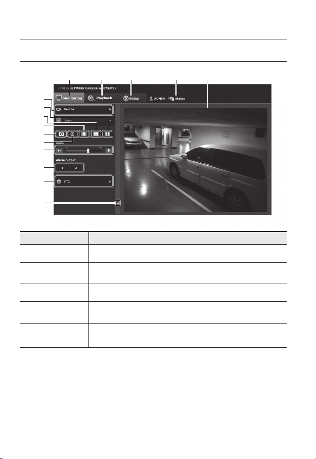
Item Description
Monitoring Move to the monitoring screen.
Playback
b
Setup Move to the Setup screen.
c
Profile access
information
Viewer Screen
Move to the screen where you can search for the video recording saved in your SD
memory card or NAS.
You can read the profile information.
Displays the Live video on the screen.
You can use the mouse wheel to activate the digital zooming in Viewer screen.
58_ web viewer
Page 59

Item Description
You can select a profile type in <Video profile> under the <Basic> setup menu.
When the Web Viewer is connected, the profile information currently using is
displayed.
Afterimages can be displayed on the screen under the following conditions if the
J
Profile type
Screen
Optimization
Fix the resolution
Full Screen Switch the current video to the maximum size of the monitor.
Capture Saves the snapshot as an image file in the .jpg format.
Manual recording
Audio/Microphone
Control
Alarm output Activate the Alarm Out port.
m
PTZ Control the pan/tilt/zoom operations of the camera.
n
Hide the context
menu
video is played in the monitoring page:
The resolution is changed due to a profile change.
-
Incoming data is being slowed due to a network delay when the profile is
-
changed.
The web browser window size and location is changed.
-
The video size of the camera will switch to as big as the Web browser.
Regardless of the resolution setup configured in the camera, it sets the resolution to
640x480. Press it again to switch back to the default resolution.
Users can save their video in the SD memory card or NAS on their own.
To take video manually, change the recording setting first. Refer to “Storage” for
how to set recording (page 114).
Enable Audio and Microphone are control the Audio volume.
Only the Audio volume can be controlled.
The left-corner context menu will disappear but only the menu icon.
● WEB VIEWER
English _59
Page 60
web viewer
To capture the snapshot
1. Click [Capture ( )] on the scene to capture.
2. When a captured video is saved, a notification message appears.
When using Internet Explorer, the captured video is saved in My Computer / My
Documents / Pictures.
In Mac OS, it is saved in “~/Pictures” or “/Users/{user account}/Pictures/”.
If you encounter an interrupted video when capturing the image with IE8 on a Windows 7-based
M
PC, deselect “Turn On Protected Mode” from “Tools – Internet Options – Security”.
If the screen is not captured by IE browser in Windows 7 or 8, run the IE Browser with the Admin
privilege.
How to record videos manually
1. Press [Manual recording ( )].
2. To end the recording, press [Manual recording ( )] again.
After inserting the SD card, go to <Event> - <Storage> and turn on the SD card by selecting “On”
M
or turn on NAS by selecting “On” after connecting to it. Then you can use the manual recording
function.
To fit the full screen
1. Click the [Full Screen (
2. This will fit the Viewer to the full screen.
3. To exit the full screen mode, press [Esc] on the keyboard.
For the Internet Explorer and Google Chrome browser, you can switch to the full screen.
M
)] button.
To Use Microphone
Click [Mic ( )] icon to activate the microphone.
60_ web viewer
Page 61
To Use Audio
1. Click [Audio ( )] icon to activate audio communication.
2. Use [
] bar to control the volume.
If there is no sound from pulling in and out the audio jack while it is in operation, click the
M
[Audio (
)] icon to enable it again.
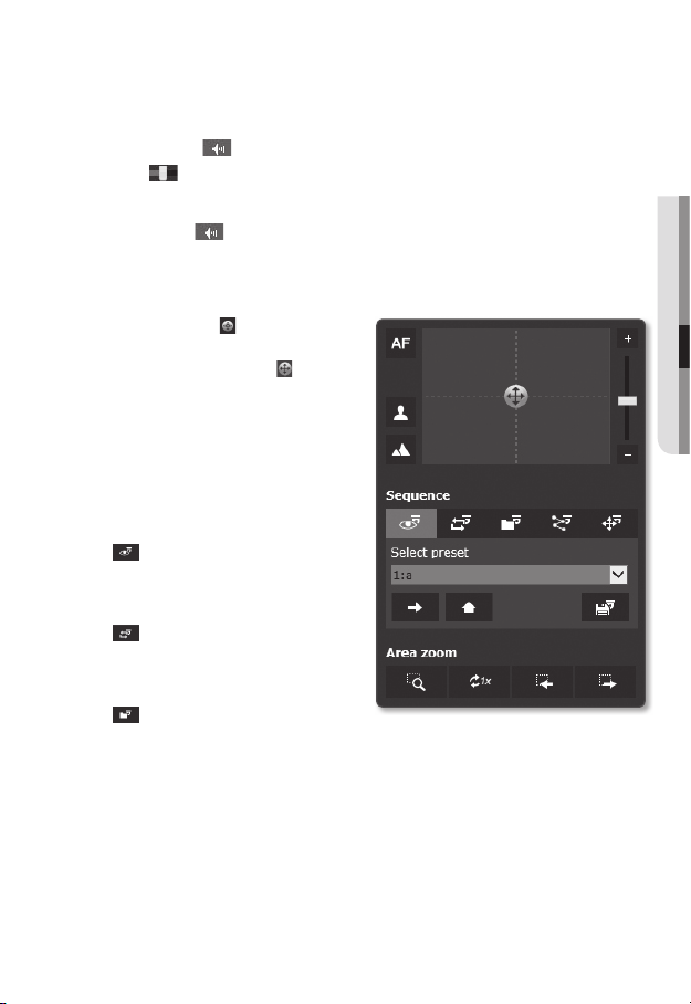
To control the PTZ
1. Press the [PTZ ( )] tab.
2. Adjust the direction of the camera
by controlling the cursor [ ] of the
screen moving pad, or control the
zoom or focus.
For further details on PTZ use, refer to
M
“PTZ setup”. (page 80)
To run a sequence
•
: Run a saved preset.
Refer to “To configure the detailed
settings for the preset” for details of
preset setting. (page 82)
•
: Run a saved swing.
Refer to “To configure the swing
settings” for details of swing setting.
(page 83)
•
: Run a saved group.
Refer to “To set a group” for details of group setting. (page 84)
● WEB VIEWER
English _61
Page 62
web viewer
•
: Run a saved tour.
Refer to “To configure the tour settings” for details of tour setting. (page 85)
•
: Run a saved trace.
Refer to “To set the tracing function” for details of trace setting. (page 85)
•
: Run a saved home position.
Refer to “To add the home position” for details of home position setting. (page 81)
•
: Configure preset.
For details on preset configuration, see “To configure the detailed settings for the
preset”. (page 82)
To enable the Area Zoom mode
•
: For zoom movement, click and drag to the location on the screen that you want
to move to.
•
: Change the current zoom factor to x1.
•
: Return to the previous area and settings.
•
: If navigated with Prev, it is switched to area and setting before navigation.
62_ web viewer
Page 63
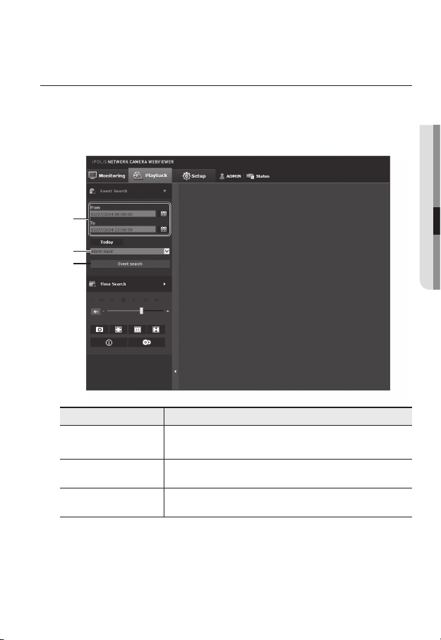
PLAYING THE RECORDED VIDEO
Before you can play the video, you must configure the record settings. For details on record settings,
M
refer to “Storage”. (page 114)
Name of event search screen and its function
b
c
Item Description
Search range setting
Search event setting Set the event type to search within the search period.
b
Set the search date and time range for data saved in your SD memory card
or NAS.
● WEB VIEWER
Event search Run the event search.
c
English _63
Page 64

web viewer
To play the content after searching by event
1. Click the [Playback ( )] button.
2. Specify the start time and end time of
your search.
3. Select an event type for your search
within the specified period.
4. Click the [Event search] button.
The search results will be displayed in
the list.
If more than 800 events are recorded
M
within the search period, your search will be limited up to the date when the 800th event is
recorded.
For instance, if the search period is between 10th and 15th day of the month, and more than 800
events were recorded 10th through 11th, your search will be limited up to 11th day with a total of
800 events, and events after then (from 12th) will not be found.
5. Select a data item to play in the search
list.
6. Click the [Play (
7. To stop playing the video, click
[Stop (
8. To return to the search screen,
click [Exit (
)] button.
)].
)].
64_ web viewer
Page 65

Name of time search screen and its function
b
c
Item Description
Time bar The section in the specific period is played by moving the time bar.
Search date setting
b
Speaker
c
Screen optimization The camera image is converted to fit the Web browser window.
Fix the resolution
Capture The current image is saved as a .jpg image file.
Set the search date using the calendar.
If there is data saved in your SD memory card or NAS on the day, it is
marked as a box on the calendar.
To listen to a voice signal (if present) in the recorded video, then activate the
voice signal icon when you play it.
Regardless of the resolution setup configured in the camera, it sets
the resolution to 800x600. Press it again to switch back to the default
resolution.
● WEB VIEWER
Full screen The current image is converted to cover the maximum size of the monitor.
English _65
Page 66

web viewer
Item Description
Video information Time data of the replayed video is displayed on the screen.
Set the desired date to make a backup copy of video data saved in your SD
Backup
To play after searching by time
1. Click [Time Search ( )].
2. Click a desired date in the calendar.
The video on the specified date will be
played.
3. If the video playback is stopped, select
a time and click [Play (
The video on the selected time will be
played.
4. While the video is being played, the
recording time for the current video will be shown.
5. Search for the video forward or backward, and control the play speed.
- How to Control the Play Interval
: Select this button to move 1 frame forward.
: Select this button to move 1 second back.
- To control the play speed
If selecting ), the button will switch to x1, x2, x4, x8, and the play speed will
increase accordingly.
Whenever you press the ( button, the reverse speed increases from -1x to -2x, -4x
and -8x.
- To control the playback direction
If you see the ) button with the play speed displayed, the video will be played
forward; Whereas, if you see the ( button with the play speed displayed, the video
will be played backward.
- How to set the time bar
If you press the
If you press the
can be selected more easily.
memory card or NAS.
Can be set as up to 5 minutes.
)].
button, the details of the time bar section can be viewed.
button, you can view a wider range of times and the desired time
66_ web viewer
Page 67

6. Move [Time bar (
The time containing a normal recoding file will be highlighted in blue; the time with
the event recording will be highlighted in red.
)] to a desired time point of the video before playing it.
To back up the searched video
1. During playback, click [ ] on the
scene to back up.
The scheduling window for backup
start and end time appears.
2. Click [
The Save As window appears.
3. Confirm the save path and click [Save]
button.
The screenshot will be backed up to
the specified path.
] button.
To play the backup video
The backed up images are saved in an .avi format. Gom Player, VLC Player, and Window
Media Player are recommended as the media player compatible with this format.
In case of Windows Media Player, download the latest codec from www.windows7codecs.com
M
and install it prior to use.
● WEB VIEWER
English _67
Page 68

web viewer
To Play an AVI File
(1) SD memory card
1. Separate the SD memory card from the camera.
Before separating the SD memory card, set the <Device> to <Off> in the “Setup Event
J
Storage” menu.
2. Insert the SD memory card into the PC.
3. Play the AVI file in the “\ch00\img\
YYYY_mm_DD\AVI” directory, using a
media player.
A filename starts with the format “001_
M
YYYYMMDD_HHMMSS.avi” and the file
number is incremented by one.
YYYYMMDD_HHMMSS indicates the start
time of data saving.
“001_YYYYMMDD_HHMMSS.smi” file
is a caption file, and you can view it if it
exists in the same directory as its related
AVI file.
The max recording time per AVI file is 5
minutes.
Once corrupted, the data in the SD memory card cannot be replayed in the Web Viewer’s
[Playback].
68_ web viewer
Page 69

(2) NAS (Network-Attached Storage)
1. In Windows browser, use \\<ip
address>\ to access.
ex)\\192.168.20.31\defaultfolder\ch01\
img\2013_07_02\AVI
2. Go to <Computer> <Network drive
connection> Enter 1.
3. Connected to the NAS.
The directory structure is same as the
directory structure for a SD memory
card.
A filename starts with the format “001_
M
YYYYMMDD_HHMMSS.avi” and the file
number is incremented by one.
YYYYMMDD_HHMMSS indicates the start time of data saving.
“001_YYYYMMDD_HHMMSS.smi” file is a caption file, and you can view it if it exists in the
same directory as its related AVI file.
The max recording time per AVI file is 30 minutes.
If you change or damage the saved data on your own, it will not play back or save properly.
● WEB VIEWER
English _69
Page 70

setup screen
SETUP
On the network, you can set up basic information on the camera, video and audio, network
events and system.
(
)
]
1. In the Live screen, click [Setup
2. The Setup screen appears.
The setting page for preview video requires the STW web viewer plug-in to be installed on the PC.
J
If it is not intalled properly, the installation page automatically apprears.
BASIC SETUP
Video profile
1. From the Setup menu, select the
<Basic ( )> tab.
2. Click <Video profile>.
3. Set the <Video profile connection
policy>.
• Keep connection when profile setting
is changed : Output uses the same
settings even when the settings of
the active profile are changed.
If not selected, changing a profile
used by an existing connection
resets such connection.
.
70_ setup screen
Page 71

4. Select each profile properties.
For more details, refer to “To Add/Change the Video Profile”. (Page 73)
5. Click the input box of each item and enter / select a desired value.
The context menu may differ depending on the selected codec type.
• Default profile : If no profile is selected when using the Web Viewer, the default
video profile is applied.
• E-mail/FTP profile : Video profile to be transferred to the specified email or FTP
site.
Only the MJPEG codec can be set as the E-mail/FTP profile.
• Record profile : This is the profile applied to video recording on SD card or NAS.
• Audio-In : Sets whether to use audio for video recordings.
6. According to your situation, set ATC (Auto Transmit Control) mode.
• ATC mode : It adjusts the video
properties according to the variance
in the network bandwidth, controlling
the bit rate. Adjusting the bit rate
depends on the ATC mode.
- Control framerate : Reduce the frame rate if the network bandwidth drops down.
- Control compression : Control the compression rate if the network bandwidth
drops down.
Compression adjustment can cause deterioration of the image quality.
If <Bitrate control> is set to <CBR>, the encoding priority according to the ATC mode will be
fixed as below:
Bitrate control / ATC mode Control compression
CBR Compression
● SETUP SCREEN
English _71
Page 72

setup screen
• ATC sensitivity : Affect the transfer rate according to the variance in the network
bandwidth.
The transfer rate will be adjusted to the fastest if the bandwidth is <Very high>,
and adjusted to the latest if the bandwidth is <Very low>.
• ATC limit : If the quality or frame rate is adjusted, the property will be changed to
the applied value (%) against the previous setting value (100%).
Note that if you reduce the property value too much, you may encounter flickering
on the screen. So it is advisable to adjust the value within the threshold.
It is recommended to apply ATC control only for cameras supporting ATC.
J
Set the ATC sensitivity to <Very low> in a network environment with high variance in the network
bandwidth.
If the network connection is unstable, you may encounter flickering on the screen.
7. When done, click [Apply (
)].
MJPEG, H264 is the default profile and you cannot delete it or change the name and codec.
M
72_ setup screen
Page 73
To Add/Change the Video Profile
The profile setup can be added or modified to accommodate various profiles depending on
the recording conditions.
1. Select one from the <Video profile> options.
2. Provide the name and select a codec.
3. Specify the conditions under which the codec will be applied.
4. Specify the details of the selected codec including resolution and frame rate.
Click <Advanced> to display the context menu.
• Resolution : Set the video size of the H.264 and MJPEG files.
• Framerate : Set the max number of video frames per sec.
The <Sensor> mode setup in Video Setup changes the maximum configurable framerate.
M
Sensor 25 fps 30 fps
Framerate 1~25 fps 1~30 fps
• Compression : Specify the compression rate of the video.
• Maximum bitrate : Set the max bit rate of video when the bit rate control is set to
VBR.
As the bit rate can be adjusted limitedly according to the resolution, frame rate and screen
J
complexity, the actual bit rate can be greater than the maximum bit rate. So you must
consider the use conditions when setting the value.
• Target bitrate : Set the target bit rate when the bit rate control is set to CBR.
• Bitrate control : You can select one from constant bit rate and variable bit rate for
compression. Fixed bitrate means that the network transmission bitrate is fixed
while varying the video quality or frame rate, variable bitrate means that a higher
priority is placed on the video quality while varying the bitrate.
After setting the fixed bit rate for bit control, if you select the video quality priority mode,
J
depending on the complexity of the screen, the actual transmitted frame rate may differ from
the frame rate setup in order to guarantee the optimal video quality for the given bit rate.
● SETUP SCREEN
English _73
Page 74

setup screen
• Encoding priority : You can set the priority of video transmission to frame rate or
compression.
• GOV length : It specifies the distance (in terms of number of frames) between two
consecutive I-Frames in a video sequence when H.264 codec was selected. (One
I-Frame + 0~Several P-Frames)
• Profile : You can select the H.264 profiling method.
• Entropy coding : Reduce the possible compression loss due to encoding.
• Smart codec : Specify the use of Smart codec.
Can be used when the bit rate control value is set to CBR and configured under Video &
M
Audio Smart Codec. (Page 102)
• Multicast(SVNP) : Specify the use of the SVNP protocol.
- IP address : Enter an IPv4 address with which you can connect to the IPv4 network.
- Port : Specify the video communication port.
- TTL : Set the TTL for the SVNP packet.
• Multicast(RTP) : Specify the use of the RTP protocol.
- IP address : Enter an IPv4 address with which you can connect to the IPv4
network.
- Port : Specify the video communication port.
- TTL : You can set the TTL for the RTP packet.
If you set the Multicast address to 224.0.0.0~224.0.0.255, multicast may not work properly
J
in all environments. In that case, we recommend you change the multicast address.
What is GOV length?
GOV(Group of Video object planes) is a set of video frames for H.264 compression,
indicating a collection of frames from the initial I-Frame (key frame) to the next I-Frame.
GOV consists of 2 kinds of frames: I-Frame and P-Frame.
I-Frame is the basic frame for the compression, also known as Key Frame, which contains
one complete image data. P-Frame contains only the data that has changed from the
preceding I-Frame.
For H.264 codec, you can determine the GOV length.
If you set a recording profile with H.264 codec, the GOV length will be framerate/2.
74_ setup screen
Page 75

User
1. From the Setup menu, select the
<Basic ( )> tab.
2. Click <User>.
3. Provide the necessary user information.
• Administrator password change :
Change the password for the
administrator.
For the security purposes, you are
J
recommended to use a combination
of numbers, alphabets uppercase and
lowercase and special characters for
your password.
It is recommended to change your
password once every three months.
The password length and limits are shown as follows.
A combination of at least three types of upper case, lower case, numeric, and special
-
characters: 8 to 9 characters.
A combination of at least two types of upper case, lower case, numeric, and special
-
characters: 10 to 15 characters.
Should be different from the ID.
-
Cannot repeat the same letter, number of special characters more than 4 times.
-
Don’t use 4 or more characters consecutive together. (examples : 1234, abcd)
-
Don’t use 4 or more characters repeated. (examples : !!!!, 1111, aaaa)
-
Special characters that are allowed. : ~`!@#$%^*()_-+=|{}[].?/
-
After the factory setting, the admin and user passwords are initialized. You need to reset
-
the password.
When you access the camera web page for the first time or access it after the initialization,
-
you will be moved to the admin password setting menu.
In this menu, you need to login again with the new password before using the camera web
-
page menus.
● SETUP SCREEN
English _75
Page 76

setup screen
If the existing password is not matched, when you change the admin password, you
-
cannot change the password.
After changing your password, if there is a camera connected to a CMS or NVR client,
-
then you need to re-register it with the newly changed password. If the camera is still
connected with the same password, then the account may be locked because a client
uses the previous password.
If you try to login with the registered account, 5 or more consecutive password authentication
has failed, and then the account may be locked for thirty seconds.
When the password is changed while multiple connections are active from a PC, the browser
may malfunction. In that case, reconnect to the server.
• Guest setup : If you select <Enable guest access>, the guest account can access
the Web viewer screen but can only view the live Viewer screen.
The ID/password for the guest account is <guest/guest>, which cannot be changed.
• Authentication setup : If you select <Enable RTSP connection without
authentication>, you can access RTSP without logging in and view the video.
• Current users : If you select <Use>, you can set or change the user permissions.
The administrator can set the audio input, audio output, alarm output and PTZ control permissions.
Profile : If you select <Default>, you can only see the default profile video; if selecting <All>, you
can see the full profile videos.
ONVIF functions available to a registered user allowed to use ONVIF functions are limited to those
J
of granted with permission.
Video Transfer and Changing Video Information: Set the profile to <All>, and set Audio Input and
Audio Output.
Video Transfer, Changing Video Information, Alarm Output : Set the profile to <All>, and select at
your preference for the rest.
PTZ control : Select <PTZ>.
4. When done, click [Apply (
)].
76_ setup screen
Page 77

Date & Time
1. From the Setup menu, select the
<Basic ( )> tab.
2. Click <Date & Time>.
3. Specify the time and date that will be
applied to the camera.
• Current system time : Displays the
current time settings of your system.
• Timezone : Specify the local time
zone based on the GMT.
• Use daylight saving time :
If checked, the time will be set one
hour before the local time zone for
the specified time period.
This option will be displayed only in areas where DST is applied.
• System time setup : Specify the time and date that will be applied to your system.
- Manual : Specify the time manually.
- Synchronize with NTP server : Sync with the time of the specified server address.
- Synchronize with PC viewer : Sets to the time of the computer connected.
4. When done, click [Apply (
When you select <Synchronize with PC viewer>, please select the appropriate standard time
J
zone for PC and camera.
)].
● SETUP SCREEN
English _77
Page 78
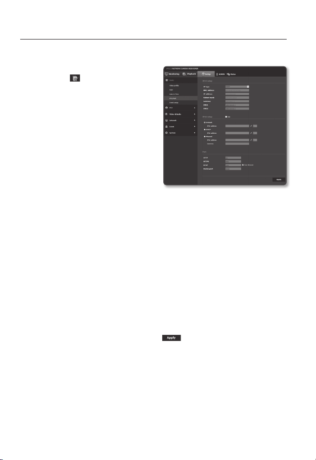
setup screen
IP & Port
1. From the Setup menu, select the
<Basic ( )> tab.
2. Click <IP & Port>.
3. Set the <IPv4 setup>.
• IP type : Select an IP connection type.
- Manual : Specify the IP address,
Subnet mask, Gateway, DNS1,
and DNS2.
- DHCP : Specify the DNS1 and
DNS2.
- PPPoE : Specify the DNS1, DNS2,
ID and Password.
If you set it to <Manual>, you should
specify the IP, Subnet mask, Gateway, DNS 1 & 2 manually.
• MAC address : Shows the MAC address.
• IP address : Displays the current IP address.
• Subnet mask : Displays the <Subnet mask> for the set IP.
• Gateway : Displays the <Gateway> for the set IP.
• DNS1/DNS2 : Displays the DNS(Domain Name Service) server address.
4. Set the <IPv6 setup>.
Set to <Use> to use IPv6 address.
• Default : Use the default IPv6 address.
• DHCP : Display and use the IPv6 address obtained from the DHCP server.
• Manual : Enter IP address and gateway manually and use it.
The IP addressing system will be defaulted to DHCP. If no DHCP server is found, the previous
J
settings will be restored automatically.
Once completed with editing, click [Apply ( )] to apply changes and the browser exits.
After a while, connect again with the changed IP.
78_ setup screen
Page 79
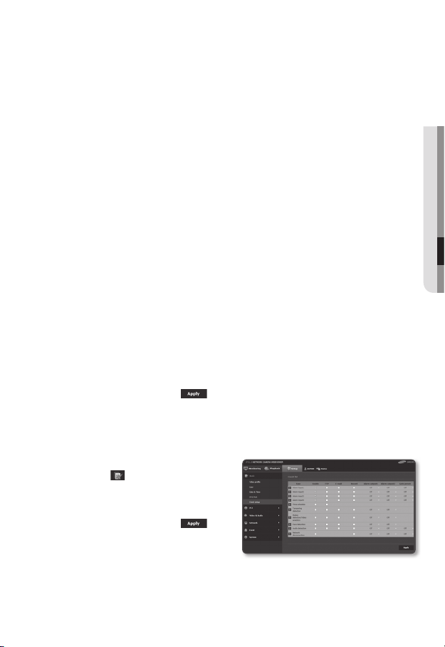
5. Type in each item in the Port menu as necessary.
Neither the port range between 0 and 1023 nor port 3702 is available.
• HTTP : HTTP port used to access the camera via the web browser.
The default is 80(TCP).
Setting the HTTP port for Safari and Google Chrome browsers to 65535 is not allowed by security
policy.
• HTTPS : In this version, the security of the web communication protocol HTTP is
strengthened. It can be used when you set HTTPS mode in SSL.
The initial value is set to 443(TCP).
The available setting range is 1024~65535. (For security reasons, in your Safari or Google Chrome
browser, you may not use 65535 as your HTTPS port.)
• RTSP : Used to transfer videos in the RTSP mode; the default is 554.
• Use timeout : When connecting to RTSP, this function resets the connection if
there’s no response for a certain time.
• Device port : Set a port used to transfer video signals with the Samsung
protocols.
If changed the HTTP port, the browser exits.
M
Afterwards, address should contain the newly assigned HTTP port trailing the IP.
ex) IP address: 192.168.1.100, HTTP port : Assigned 8080 http://192.168.1.100:8080
(If HTTP port is set to 80, no need to specify the port number)
Using RTSP and HTTPS is recommended in order to prevent the image information from being
restored.
6. When done, click [Apply (
)].
Event setup
You can easily set the event detection items, and move to the detailed setting.
1. From the Setup menu, select the
<Basic (
2. Click <Event setup>.
3. Activate desired items on the Event list.
4. When done, click [Apply (
)> tab.
)].
● SETUP SCREEN
To make detailed event settings, click
M
on your desired settings. Go to detailed
<Event> setting.
English _79
Page 80

setup screen
PTZ SETUP
Preset setup
You can change the direction of lens and activate the zoom.
1. From the Setup menu, select the <PTZ
(
)> tab.
2. Click <Preset setup>.
3. Click <▼ Show>.
4. Click the cursor [
moving pad to control movement of the
screen.
• Move screen: Scroll the cursor in the
direction desired.
• Control screen movement rate: The
further away the cursor is from the
center, the faster it moves on the
screen.
5. Control zoom movement.
• Zoom In: Move up the bar in the right
of the UI, or press the [
The farther the bar is from the center,
the faster the screen expands.
• Zoom Out: Move down the bar in the
right of the UI, or press the [
button. The farther the bar is from the
center, the faster the screen reduces
in size.
6. Adjust the focus.
• Manual focus (
• Auto focus (
] on the screen
] button.
]
/ ) : The user sets the focus.
) : The system sets the focus automatically.
When performing the sequence action at a high or low temperature, the system may respond
J
slower than the set rate for accurate sequence action.
80_ setup screen
Page 81

To add the home position
1. Move to a desired start screen point and press [ ].
The point will be set to the home position.
2. Click [
] in the home position. You will move to the predetermined home position.
3. When the camera is rebooted after setting, the screen is located at the home
position. (If the camera was on another sequence operation, the sequence is
performed.)
To add a preset
1. Click on the [ ] button.
2. Select the preset number to be added.
3. Set the preset name and click on the [OK] button.
To delete a preset
1. Select the preset number to delete.
2. Press the [ ] button.
To move to a desired preset
1. Click preset number you want to move in the preset settings.
● SETUP SCREEN
English _81
Page 82

setup screen
To configure the detailed settings for the preset
1. Select the number of preset that you
want to configure.
• After action : In the <After action>,
you can select auto execution/video
analysis operation after the preset
operation. (This setting does not
apply in the swing function.)
- Auto run : The sequence setting
for auto execution is performed. If
you turn off the function or if there
is no auto-executing operation, the
preset operation status is maintained. (This setting is not applied if preset is run
with a group or tour function.)
- Video analysis : MD/VA operation is run.
• Camera setup : You can change the camera setting to the environment of the
selected preset.
Refer to “Camera setup” for how to set the camera. (page 93)
• MD / VA : You can set the system to generate an event signal when a movement
is detected in the preset, or an intelligent video analysis event is detected.
For more details, refer to “MD / VA”. (Page 126)
2. When done, click [Apply (
After saving the preset setting, make sure to select <Sequence Setup> or run the preset. If
J
the operation is not performed, the system may run a wrong operation, such as an unintended
change of preset setting.
While setting preset edit, you cannot use the functions, such as preset setting, home position
setting and move to the home position.
)].
82_ setup screen
Page 83

PTZ sequence
1. From the Setup menu, select the <PTZ
( )> tab.
2. Click <PTZ sequence>.
3. Set swing, group, tour, tracing & auto
operation.
To configure the swing settings
Swing is a monitoring function that moves
between two preset points and enables you
to trace the motion.
1. Select <Swing>.
The menu screen will switch to the
swing setting screen.
2. Select a swing setting mode.
• Pan : You can set the swing
monitoring using the PAN function.
• Tilt : You can set the swing
monitoring using the Tilt function.
• Pan&Tilt : You can set the swing monitoring only using both PAN and Tilt
functions.
3. Set <First preset> and <Second preset> to specify a swing range.
When moving to the second preset from the first preset, the camera will move to the right
J
direction on the screen.
If you set <Flip/Mirror> to <On> in the video setup, it will move in the opposite direction. (Page 90)
4. Set movement speed and switching time.
5. Press the [ ] button.
The first preset, the second preset, speed, and switching time are saved in
accordance with the mode.
6. Press the [
It performs the swing operation.
7. Press the [ ] button.
The running swing will be stop.
If you want to set the swing, then you need at least two presets set already.
J
] button.
● SETUP SCREEN
English _83
Page 84
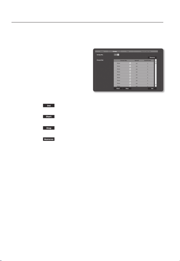
setup screen
To set a group
The group function enables you to group various presets before calling them in sequence.
Six groups can save a total of 128 presets each.
1. Select <Group>.
The menu screen will switch to the
group setting screen.
2. Select a group setting mode.
• Group No. : Select a group number.
• Preset No. : Select a preset number.
• Speed : Specify the speed of
movement.
• Dwell time : Specify the duration for
which an operation is kept at the preset position.
3. Press the [
Saved in the bottom list.
4. Press the [ ] button.
It performs the group operation.
5. Press the [ ] button.
The running group will be stop.
6. Press the [
Selected group data will be deleted.
] button.
] button.
84_ setup screen
Page 85

To configure the tour settings
The tour function enables you to call groups of your presets in sequence.
1. Select <Tour>.
The menu screen will switch to the tour
setting screen.
2. Configure the tour settings in detail.
• Group No. : Select a group number.
• Dwell time : Specify a waiting time
before a new group is called.
3. Press the [
] button.
Saved in the bottom list.
4. Press the [
] button.
It performs the tour operation.
5. Press the [ ] button.
The running tour will be stop.
6. Press the [ ] button.
Selected tour data will be deleted.
To set the tracing function
Tracking remembers the trace of movements instructed using the direction button and
reproduces it for your reference.
1. Select <Trace & Auto Run>.
This will bring up the tracing and auto
operation setting menu screen.
2. Select a tracking number.
The operation will be saved with display of the memory usage. The saving time
differs, depending on the level of the PTZ operation.
If memory is filled to 100% or the recording end configuration is not completed in
2 minutes from the beginning of saving, it will be automatically terminated.
● SETUP SCREEN
English _85
Page 86

setup screen
3. Press the [ ] button.
Selected tracing number will be saved.
4. Move the navigation path of saving using the pan/tilt/zoom.
5. Press the [ ] button.
Saving is terminated.
6. Press the [
Selected tracing number will be activated as set.
To set the auto run
This feature will activate the predefined sequence function if the user does not manipulate
anything on the product for a certain time.
1. Select <Trace & Auto Run>.
This will bring up the tracing and auto
operation setting menu screen.
2. Select an auto run mode.
• Home : It is moved to the home
position.
• Preset : It is moved to the selected preset number.
• Swing : Automatically executes the operation in Swing mode.
• Group : Automatically executes the operation in Group mode.
• Tour : Automatically executes the operation in Tour mode.
• Trace : Automatically executes the operation in Trace mode.
• Auto pan : Automatically executes the 360° rotation in the pan direction.
You can designate the tilt angle and speed.
• Schedule: You can set autorun function by day / time. You can set the action in
minutes, and the default setting is home position.
3. Set the start time of autorun. After selecting the mode, select time (5s/10s/20s/30s/
1m/2m/3m/4m/5m).
4. Press the [
Selected operation will be performed automatically.
] button.
] button.
86_ setup screen
Page 87
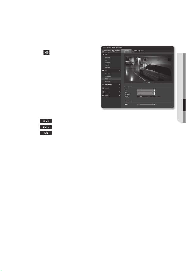
PT limit
You can specify restrictions on the pan or tilt function.
1. From the Setup menu, select the
<PTZ (
2. Click <PT limit>.
3. Decide if you want to limit the PT
operations. If so, specify the details.
4. Set the Propotional PT mode.
Pan and tilt speed is adjusted according to the zoom magnification. As the zoom
magnification grows, the pan and tilt speed decreases.
)> tab.
• Mode : Select a mode to set
between Pan limit and Tilt limit.
• Use : Select whether to use limit in
set mode.
• Tilt range : The tilt limiting range is
selected.
Select -5º~185º or -15º~195º.
• Action : PT limiting operation is set.
-[
] : Start limit setting.
] : Provide the start and end points.
-[
-[
] : If you want to change the point setting, click this to return to the
input dialog.
• Off : Turns off the zoom interworking mode.
• Slow : The manual pan and tilt control speed is changed according to the zoom
magnification. It slows down by 20%.
• Normal : he manual pan and tilt control speed is changed according to the zoom
magnification.
• Fast : the manual pan and tilt control speed is changed according to the zoom
magnification. It speeds up by 20%.
● SETUP SCREEN
English _87
Page 88
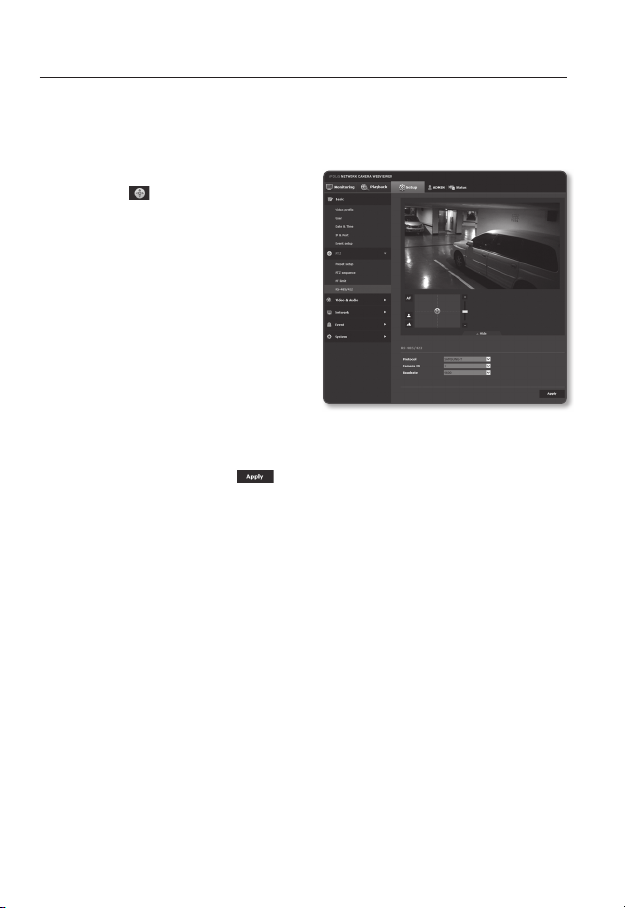
setup screen
RS-485/422
Configure the controller connection so that the camera’s PTZ can be controlled using the
controller connected to the camera’s RS-485/422 terminal.
1. From the Setup menu, select the
<PTZ (
2. Click <RS-485/422>.
3. Click <▼ Show>.
4. Specify the serial port.
The communication protocol used by
the controller connected to the network
camera can be set (RS-485/422).
5. When done, click [Apply (
)> tab.
• Protocol : Select the same protocol
version as the controller, choosing
from SAMSUNG-T / SAMSUNG-E /
PELCO-D / PELCO-P / PANASONIC
/ HONEYWELL / AD / VICON / GE /
BOSCH.
• Camera ID : Set the camera ID (1-255).
• Baudrate : Set the RS-485/422 communication speed.
)].
For this operation, the network camera and controller must be properly connected. Also, the
M
controller must have a serial port set to control the camera.
There may be functions that are not supported depending on the controller or protocol
J
specifications. Please see the following table for details.
88_ setup screen
Page 89

Functions Supported for Each Protocol
Zoom
Protocol P control P movement
SAMSUNG-T OOOOOOO XOO
SAMSUNG-E OOOOOOO XOO
PELCO-D OOOOOOOXOO
PELCO-P OOOOOOOXOO
PANASONIC OOOOOOOXOO
HONEYWELL OOOOO XOX OO
AD OOOOOXO XOO
VICON OOOOOXOXOO
GE OOOOOOOXOO
BOSCH OOOOOOOX OO
Company Protocol Name Version
AD RS-422/RS-485 Communications REV.B
BOSCH AutoDome Protocol 5/30/11
GE Calibur ImpacNet(RS485 Protocol) REV.4.01(05/21/2004)
HONEYWELL ScanDomeII Protocol V1.05(02/11/2004)
PANASONIC WV-CS950 Protocol VER,4.0
PELCO-D “D” Protocol Ver.4, Rev.1(4/7/2004)
PELCO-P “P” Protocol
SAMSUNG-E Samsung Protocol Ver. 2.3(2006/09)
VICON
speed
T control T movement
Zoom
movement
control
speed
RS-422 Receiver Communications
speed
Protocol
Focus
control
Focus
control
speed
Preset
Preset
save
movement
Rev 404(4/08/04)
Remarks
● SETUP SCREEN
English _89
Page 90
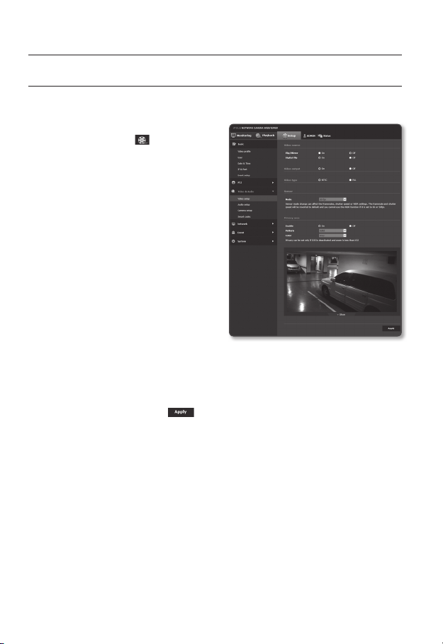
setup screen
VIDEO & AUDIO SETUP
Video setup
1. From the Setup menu, select the
<Video & Audio (
2. Click <Video setup>.
3. Select a <Video source> mode.
• Flip/Mirror : Displays the video from
the camera upside down or reversely.
• Digital Flip : This limits the vertical
screen navigation range of the
camera lens.
4. Click Activate or Inactivate of the analog
video output function.
5. Select the matching <Video type> of
the display equipment.
6. Select the sensor mode.
You can set the number of frames
captured by the CMOS sensor per
second.
Refer to “Video profile” for the framerate setup range of the <Video profile> according to mode
M
setup. (Page 7
7. Specify the privacy zone.
8. When done, click [Apply ( )].
)> tab.
0)
90_ setup screen
Page 91

To set the privacy zone
You can specify a certain area of the camera video to be protected for your privacy.
1. Set it to <On>.
2. Select the pattern and color of the
privacy field to be set.
3. When done, click [Apply (
4. Click <▼ Show>.
5. Place the cursor at a point in the video
and drag it to whatever you need.
Move the set area to the center of the
screen by controlling pan/tilt.
6. Check whether the field indicated on
the screen is consistent with the field to
be set and enter the name. When not
using the zoom indication restriction
function, select [Off] and then click on
the [OK] button. If the displayed field
and setting field are different, press on
the [Cancel] button and reset.
7. When using the zoom indication restriction function, select [On] and click on the [OK]
button. The privacy field will be set and a popup will appear. At this time, move to
the zoom position that you wish to set for the zoom operation and click on the [OK]
button. To cancel the privacy field setting, click on the [Cancel] button and reset.
The privacy field can be set only when shaking compensation (DIS, digital image stabilizer) is not used
M
and when zoom is under 32x.
Privacy fields that apply zoom indication restriction functions are shown with [zoom] following the
name.
)].
● SETUP SCREEN
English _91
Page 92
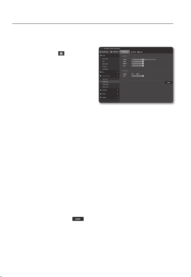
setup screen
Audio setup
You can configure the I/O settings of the audio source from the camera.
1. From the Setup menu, select the
<Video & Audio (
2. Click <Audio setup>.
3. Set the audio input value.
• Source : Sets the audio input.
- Line : Connect the cable to the
audio device.
- External microphone : 3.5 pi(¢)
mono type external MIC.
• Apply power to Ext. Mic. : If the
external microphone connected has no separate power supply, check this option
to set camera to supply power to the connected external microphone. The option
is enabled if <External microphone> is selected.
• Codec : Specify the audio codec.
- G.711 : A audio codec standard, it uses 64 Kbps PCM (Pulse Code Modulation)
encoding.
ITU standard audio codec that is adequate for digital voice transfer in PSTN
network or through a PBX.
- G.726 : ITU standard audio codec applying ADPCM (Adaptive Differential Pulse
Code Modulation) for variable bit rates of 40/32/24/16 Kbps to 64 Kbps PCM
encoding.
• Bitrate : Set the bit rate to differentiate compression ratio if using G.726 codec.
• Gain : Specify the audio input amplification.
Excessive volume or gain values from the sound source may cause problems such as degradation
M
in sound quality or howling.
4. Set the audio output level.
• Enable : Sets whether to use audio output.
• Gain : Set the amplification value for the audio output.
5. When done, click [Apply (
)> tab.
)].
92_ setup screen
Page 93
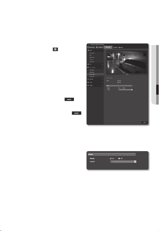
Camera setup
You can change the camera settings according to the environment where the camera is
located.
1. From the Setup menu, select the
<Video & Audio (
2. Click <Camera setup>.
3. Select the camera setting type.
• Global : The camera is set to be
suitable for the image location.
• Preset : The camera is set at the
location specified in <Preset setup>.
4. Configure the settings as necessary
of : SSDR, White balance, Back light,
Exposure, Special, Focus, OSD
5. When done, click [Apply (
If a certain time (timeout: 240s) is elapsed
M
with your not pressing the [Apply (
button after changing the settings, your
changes will not be applied.
SSDR (Samsung Super Dynamic Range) Setup
In a scene where the difference between bright and dark is severe, you can increase the
brightness of the dark area alone to regulate the overall brightness.
1. Select <SSDR>.
2. Set <Mode> to <On>.
3. Configure the <Level> setting as
necessary.
• Level : Adjust the level of the dynamic range.
)> tab.
)].
)]
● SETUP SCREEN
English _93
Page 94

setup screen
White balance Setup
You can correct the image colors based on white under any lighting conditions.
1. Select <White balance>.
2. Select <Mode>.
• ATW : Corrects the colors of the
camera video automatically.
ATW does not work under mercury/
sodium lamps.
• Manual : You can adjust the red and blue gains of the camera video manually.
• AWC : Corrects the colors of the camera video to be optimized to the
current lighting condition and screen mode.
To obtain the optimal condition for the current lighting, put the focus of the
camera to a white paper and press the [Set] button. If the lighting environment is
changed, you should readjust the settings accordingly.
• Outdoor : Automatically corrects the video colors of the camera to be
optimized to the outdoor environment.
• Indoor : Automatically corrects the video colors of the camera to be optimized to
the indoor environment.
• MERCURY : The image automatically compensates to the mercury lamp
environment.
In AWC mode, click the [Set] button if you want to keep the white balance level of the current
M
image.
The white balancing may not work properly in the following conditions:
J
If this is the case, switch to AWC mode.
If the surrounding condition of the object is out of the temperature correction range
-
ex) Clear sky, sunset
If the surrounding of the object is dark
-
If the focus of the camera directly faces the florescent lighting or if the camera is installed in a
-
place of variable illumination, the white balancing operation may be unstable.
94_ setup screen
Page 95
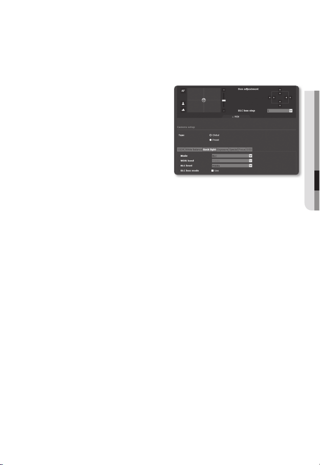
BLC Setup
You can specify a desired area on the video manually and set the area to be displayed
more clearly.
1. Select <Back light>.
2. Set <Mode> to <BLC>.
If you select BLC, the Box adjustment
screen and the BLC box step are
displayed on the PTZ Control screen.
3. Select each item and set it properly.
• BLC level : You can change the
level to adjust the brightness of the
monitoring area.
• BLC box Mode : Specify the mode of
BLC box.
• Box adjustment : Use the arrow buttons to adjust the size and position of the BLC
Box.
• BLC box Step : Specify the pixel unit for movement. You can use the arrow
buttons of <Box adjustment> to add or reduce the pixels.
● SETUP SCREEN
English _95
Page 96
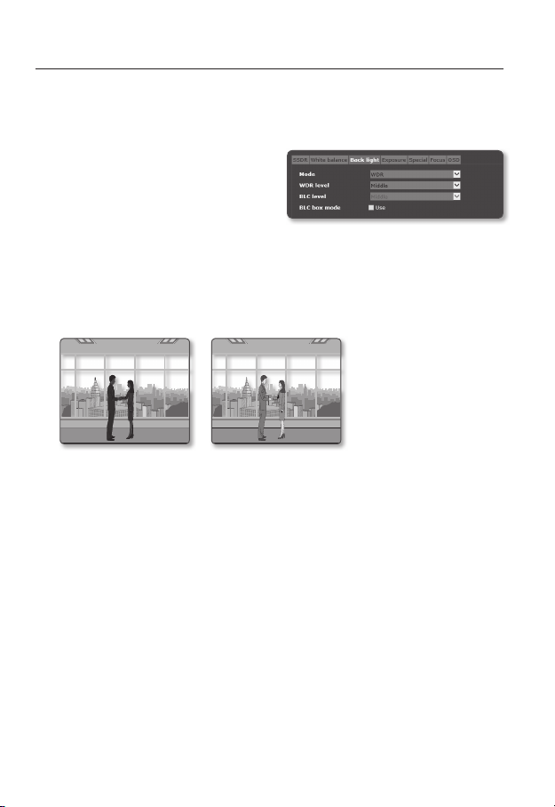
setup screen
WDR Setup
You can set to display a sharp image of the objects in a scene where both bright and dark
areas exist.
1. Select <Back light>.
2. Set <Mode> to <WDR>.
3. Select each item and set it properly.
• WDR level : Specify the WDR
sensitivity level.
If WDR mode is active, the shutter mode cannot be changed. Data transfer via the network is
M
available at up to 15 fps.
If the WDR mode is active, a moving object can cause an afterimage on the screen.
Ex)
<WDR OFF> <WDR ON>
If you select WDR, you may encounter the following problems. So set it to Not Used.
J
Unnatural change of colors that cause an unnatural image on the screen
-
Noise on the bright area of the image
-
As the performance of the WDR function may differ depending on the bright-area size of the
image, it is recommended to optimize the installation angle for the best performance.
At night operation, this function will be activated only if the incoming highlight exceeds a certain
area in a low contrast environment.
Increasing the maximum value may cause an unnatural portion of the image.
96_ setup screen
Page 97

For the best WDR performance, it is recommended to set the Iris mode to <Auto>.
Since the auto focus operation can be repeated depending on the lighting condition if user
backlight compensation is used, it is recommended to use the focusing mode of <One Shot AF>
or <Manual>.
Exposure Setup
You can adjust the exposure level of the camera.
1. Select <Exposure>.
2. Select each item and set it properly.
• Brightness : Adjust the screen
brightness.
• Minimum shutter : The limit of the
longest exposure time.
Shutter is the mode to set up the range of
the sensor exposure time which will specify
the upper and lower limits for the electronic shutter movement.
The framerate may be reduced in the dark condition if Shutter has a lower value than specified in
the Sensor mode.
• Maximum shutter : The limit of the shortest exposure time.
• Anti flicker : Select this feature if you encounter a flickering screen due to a
frequency mismatch with the ambient lighting.
• SSNR3 : Specify whether you want to remove the noises in the video.
When AGC mode is set to <Off>, SSNR3 cannot be used.
• SSNR3 level : Adjust the noise reduction level.
• Iris : You can set the camera iris to Auto or Manual to your preference.
- Auto : Automatically sets the iris adaptively to the ambient lighting and shutter
speed.
- Manual : Iris F-No is set manually.
• Iris F-No : If the iris mode is set to Manual, specify the F number of the iris.
As F-No increases, the iris decreases, so the screen is darkened, and as F-No decreases, the
screen is brightened.
• AGC : Select AGC Control mode.
Adjust the gain value of the video (that, in particular, was recorded at a low
contrast scene and had a lower brightness level than normal) to control the video
brightness.
If the AGC mode is set to <Off> or <Manual>, you cannot use SSNR3 and cannot select the
<Auto> mode for the Date/Night mode setting.
● SETUP SCREEN
English _97
Page 98

setup screen
Special Setup
1. Select <Special>.
2. Select each item and set it properly.
• DIS : Compensates the image
automatically when it is seen to
shake for stable image output.
Mitigates image blurring that occurs when
there is vibration of the camera due to
external factors like wind.
DIS cannot be used if VA/MD and tempering detection are used.
Digital zoom cannot be used if DIS is used.
• Day/Night : You can switch the mode to adjust the black and white level as well
as the colors.
- Color : Always displays the video in colors.
- B/W : Always displays the video in black and white.
- Auto : Displays in color mode during normal daytime and switches to black and
white mode in a low contrast scene at night.
When the AGC mode of <Exposure> is set to <Off>, automatic day/night mode setting cannot
be selected.
• Dwell time : This is the time while each applicable lighting condition is kept in
order to enable the switch between day and night modes.
• Duration : Specify the time interval of lighting at which the sequence operation is
triggered.
• Sharpness mode : Adjust the overall sharpness of the image.
If selecting <On>, you can adjust the sharpness of the image.
• Sharpness level : The higher the level is, the sharper and clearer the outline of the
image becomes.
98_ setup screen
Page 99

• Color level : Adjust the strength of video color.
• Defog : You can improve images in foggy or cloudy weather.
It is set to <Off> as a default. Specials are used when the video looks blurry in the
foggy weather.
- Off : Fog removal function is not active.
- Auto : Images are compensated automatically according to the amount of fog.
To improve the effects of this function, adjust the <Defog level>.
- Manual : You can set the amount of compensation manually for the image.
Use this function if the image is unclear due to foggy weather.
M
If <Auto> is selected for the defog mode, the level is reduced as the fog is reduced.
J
If you wish to maintain the fog removal level even when the amount of fog is reduced, select
<Manual>.
Note that the image can be dark if the fog level is high with the amount of fog being small.
• Defog level : Adjust the fog removal level.
● SETUP SCREEN
English _99
Page 100

setup screen
Focus Setup
1. Select <Focus>.
2. Select each item and set it properly.
• Mode
- Manual : The focus will be adjusted
manually according to the zoom
factor.
- Auto : The focus will be adjusted
automatically according to the zoom factor.
- One Shot AF : Auto Focus will be performed once after the zooming operation.
• Digital zoom : Specify the use of digital zoom.
Digital zoom cannot be used if DIS is used.
• Digital zoom limit : Specify the limit of the digital zoom.
• Zoom tracking : Specify the focus sync mode with the panning/tilting/zooming
operation.
- Off : Only the zoom lens will work.
- Auto-Track : It will control (detect and correct) the zooming operation to keep
fitting the focus.
- Tracking : The zooming operation will be guided by the focus track.
• Zoom speed : Adjust the zoom tracking speed.
• Init. lens : Reset the lens to prevent the step-out in zoom mode.
• Duration : Specify the frequency of resetting the lens.
You can specify the date of resetting the lens that will perform in auto focus mode. Specify the time
between 1 and 7 days, and the resetting will be performed at 24-hour interval starting from the
specified date.
The auto focus function might not work properly under any of the following conditions:
J
Bright or flashing lights (ex.- neon sign)
-
Low illumination of the target area
-
Slow-shutter action
-
Dark object
-
Excessive illumination of the target area
-
If a short-distance object and a long-distance object are in the target area
-
If there is no contract gap (sky, wall, etc.)
-
If the camera is taking a picture of a thin horizontal line
-
In the auto focus mode, because the camera focuses on the object at the center of the area, other
objects which are not in the center can be out of focus.
100_ setup screen
 Loading...