

Hanwha Techwin SNHV6430BNH, SNHV6430BN User Manual

SAMSUNG SMARTCAM
User Manual
SNH-V6430BN/
SNH-V6430BNH

Samsung SmartCam
User Manual
Copyright
+DQZKD7HFKZLQ
©2016
Tra de ma rk
Each of trademarks herein is registered. The name of this product and other trademarks mentioned in this
manual are the registered trademark of their respective company.
Restriction
Copyright of this document is reserved. Under no circumstances, this document shall be reproduced,
distributed or changed, partially or wholly, without formal authorization.
Disclaimer
+DQZKD7HFKZLQ
document, but no formal guarantee shall be provided. Use of this document and the subsequent results
shall be entirely on the user’s own responsibility.
contents of this document without prior notice.
For a Class B digital device or peripheral, the instructions furnished the user
shall include the following or similar statement, placed in a prominent location
in the text of the manual:
NOTE: This equipment has been tested and found to comply with the limits for
a Class B digital device, pursuant to part 15 of the FCC Rules. These limits are
designed to provide reasonable protection against harmful interference in a
residential installation. This equipment generates, uses and can radiate radio
frequency energy and, if not installed and used in accordance with the
instructions, may cause harmful interference to radio communications.
However, there is no guarantee that interference will not occur in a particular
installation. If this equipment does cause harmful interference to radio or
television reception, which can be determined by turning the equipment off
and on, the user is encouraged to try to correct the interference by one or
more of the following measures:
- Reorient or relocate the receiving antenna.
- Increase the separation between the equipment and receiver.
- Connect the equipment into an outlet on a circuit different from that to which the receiver is connected.
- Consult the dealer or an experienced radio/TV technician for help.
Co., Ltd. All rights reserved.
makes the best to verify the integrity and correctness of the contents in this
+DQZKD7HFKZLQ
reserves the right to change the
SPECIFY SERVICE INSTRUCTIONS AND WARRANTY TERMS
This device complies with Part 15 of the FCC Rules.
Operation is subject to the following two conditions: (1) this device may not cause
harmful interference, and (2) this device must accept any interference received, including
interference that may cause undesired operation.
FCC CAUTION:
Any changes or modifications in construction of this device which are not expressly
approved by the party responsible for compliance could void the user's authority to
operate the equipment.
FCC NOTE:
The manufacturer is not responsible for any radio or tv interference caused by
unauthorized modifications to this equipment.
Such modifications could void the user's authority to operate the equipment.
Operational Description
The operational description shall fulfil the requirements of Rule Part 2.1033(b)(4). The rule
part requires, "A brief description of the circuit functions of the device along with a
statement describing how the device operates. This statement should contain a
description of the ground system and antenna, if any, used with the device".
The above requirement has been further interpreted by the FCC to mean that the
description shall:
a. be an operational or technical description of how the device operates, is modulated
and meets requirements;
b. describe the EUT completely. What is it (in plain English as well as technical terms)?
Give a clear, concise functional description of device operation.
c. always describe the signal, such as modulation type, pulse repetition rate, signal type
and information being sent. Describe all modulation types and all data rates.

Instructions & Warranty
The manufacturer is not responsible for any loss or radio/TV interference caused by
The manufacturer is not responsible for any loss or radio/TV interference caused by
unauthorized modification of the product.
unauthorized modification of the product.
Such modification will void the warranty of the product as well as the user’s right of use.
To comply with FCC RF exposurre compliance requirements, a separation
distance of at least 20 cm must be maintained between the antennaof this device
and all persons. This device must not be co-located or operation in
with any otheer antenna or transmitter.
conjunction
WARNING
o The product must be assembled and installed by an adult.
o Before using, read all instructions on this manual thoroughly and follow operational
instructions, warnings on this manual and printed on the product.
o To avoid entangled power cord, do not place it around the baby bed or other infant
furniture. Keep this product and its power cord out of children’s reach.
o Especially, the power cord should be installed carefully while keeping it out of children’s
reach.
o Never use the product near bath tub, sink, washing machine and in wet basement to
avoid moisture.
o The product is not designed for medical monitoring, and requires a grown-up’s
protective supervision on its use.
o To avoid overheating of the product, do not expose the product to direct sunlight; do not
install or use near a heat source such as heater, radiator, cooking devices (ex: electric
stove or oven) and other warming devices (ex: audio amplifier, TV, etc.).
o Make sure to keep ventilated while using the product.
Avoid pillar or furniture that may block ventilation, when installing the product.
o Make sure to use the power adaptor provided. If used with unidentified adaptor, it may
damage the product. The power adaptor must be used with regular household electric
supply.
o Avoid sharp, pointed objects around the adaptor’s cable, not to damage the cable.
o Be warned and never hold the cable’s stripped part when connecting / disconnecting
the adaptor to/from the wall outlet.
o To avoid entangled cable lines, avoid using cable extension for adaptor’s power cord.
o The product’s servicing is allowed only to authorized Hanwha Techwin service
personnel.
o When using the product for children’s care, be careful to keep the product out of
children’s reach.
o The product partially contains component which might cause respiration difficulty.
Accessories and small parts of the product should be stored keeping out of children’s
reach.
o The product is not designed to replace responsibility of human supervision on children.
o The product is not equipped with device of immediate notification to adult with
accidental/sudden children‘s move; it requires periodic checks and human supervision.
o This appliance and its antenna must not be collocated or operation in conjunction with
any other antenna or transmitter. A minimum separation distance of 20 cm must be
maintained between the antenna and the person for this appliance to satisfy the RF
exposure requirements.
o Please note that the content of a micro SD card used for other purposes may be
deleted when it is mounted in the camera.

Contents
GETTING STARTED
5 Features (SNH-V6430BN)
6 Features (SNH-V6430BNH)
7 What’s Included (SNH-V6430BN)
8 What’s Included (SNH-V6430BNH)
9 Part names and functions (SNH-V6430BN)
11 Part names and functions (SNH-V6430BNH)
INSTALLATION & NETWORK CONNECTION
13 Indoor/Outdoor bracket switching
14 Installation (SNH-V6430BN)
16 Installation (SNH-V6430BNH)
18 Network Connection and Settings (SNH-V6430BN)
19 Network Connection and Settings (SNH-V6430BNH)
MONITORING
21 Registration
26 Live Video
29 Setup
36 Event Alarm
36 Playback
38 Information
APPENDIX
39 Specifications
44 Troubleshooting
G
ETTING
5 Features (SNH-V6430BN)
6 Features (SNH-V6430BNH)
7 What’s Included (SNH-V6430BN)
8 What’s Included (SNH-V6430BNH)
9 Part names and functions (SNH-V6430BN)
10 Power Supply
11 Part names and functions (SNH-V6430BNH)
12 Power Supply
S
TARTED
01
Features (SNH-V6430BN)
o Dedicated Wi-Fi Product
- The camera is registered through the Wi-Fi connection.
o Easy to install
- The Wi-Fi Direct button allows easy connection to a wireless router.
- Simply visit the home page (www.samsungsmartcam.com) and download and
install the program without a separate installer program.
o Remote monitoring
- Whenever and wherever if you are in the Internet enabled environment, remote
monitoring is ready for you.
- PC, laptop or smart phone can be used for monitoring.
o Real-time alarm
- When a motion and sound are detected, your smartphone will generate real time
alarms.
o Saving in SD card
- When an event occurs, the user can save the video in their SD card.
o Downloading a recorded video
- You can download a motion detection triggered/audio detection triggered/
manually recorded video saved on the SD card to your PC or smartphone
(Android-powered smartphone).
o Two-way Audio
- With the built-in speakers and microphone, you can make Two-way
communications.
However, it is available only with the smart phone. (Not applicable to the PC or
laptop computer.)
o Used for outdoor purposes
- You can easily install an indoor camera in an outdoor space using the housing for
outdoor use.
01
Getting Started
5

Features (SNH-V6430BNH)
o Easy to install
- The Wi-Fi Direct button allows easy connection to a wireless router.
- Simply visit the home page (www.samsungsmartcam.com) and download and
install the program without a separate installer program.
o Remote monitoring
- Whenever and wherever if you are in the Internet enabled environment, remote
monitoring is ready for you.
- PC, laptop or smart phone can be used for monitoring.
o Real-time alarm
- When a motion and sound are detected, your smartphone will generate real time
alarms.
o Saving in SD card
- When an event occurs, the user can save the video in their SD card.
o Downloading a recorded video
- You can download a motion detection triggered/audio detection triggered/
manually recorded video saved on the SD card to your PC or smartphone
(Android-powered smartphone).
o Dustproof/Waterproof (weather resistant)
- The dustproof and waterproof design enables it to be installed in outdoor spaces
that are exposed to dust and rain.
o PoE connection
- You can easily connect the camera to the power supply and network using a PoE
adapter, even in a demanding installation environment.
6
· English
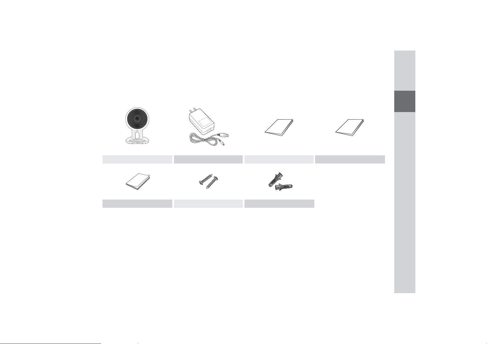
What’s Included (SNH-V6430BN)
Check for components when opening the product package.
Camera Power adapter and cable Quick Start Guide Warranty Card
GPL Lisence Tapping screw Plastic anchor
` Keep the packing container. You will need the serial number later to register the camera.
n
01
Getting Started
7
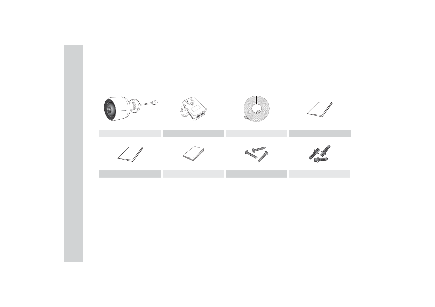
What’s Included (SNH-V6430BNH)
Check for components when opening the product package.
Camera PoE adapter & power plug LAN cable (10M) Quick Start Guide
Warranty Card GPL Lisence Tapping screw Plastic anchor
` Keep the packing container. You will need the serial number later to register the camera.
n
8
· English
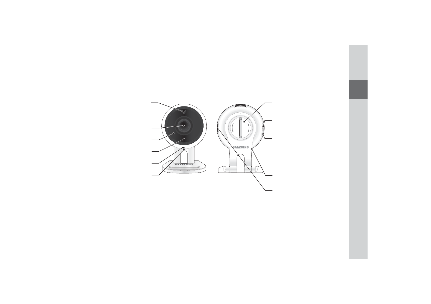
Part names and functions (SNH-V6430BN)
01
Detects light levels where the camera is placed.
Luminance Sensor
Night vision mode changes according to detection
result.
Camera lens
Built-in IR LEDs for night vision
Built-in microphone
Power/Wi-Fi status LED
Power Connection Button
It connects with a power adapter.
Bracket knob
Connect the camera and bracket.
7
,
*
1
(
+
6
7
2
(
1
2
/
Wi-Fi Direct button
Wi-Fi is used for wireless communication between
camera and smartphone.
5(6(7
Getting Started
Reset button
Resets the camera settings to the default.
The system restarts if you press the button for 10
seconds using a pointed object such as a needle.
` If you press too strongly, the button can break.
J
Speakers
Generate audio output from your smart phone.
Micro card insertion hole
9
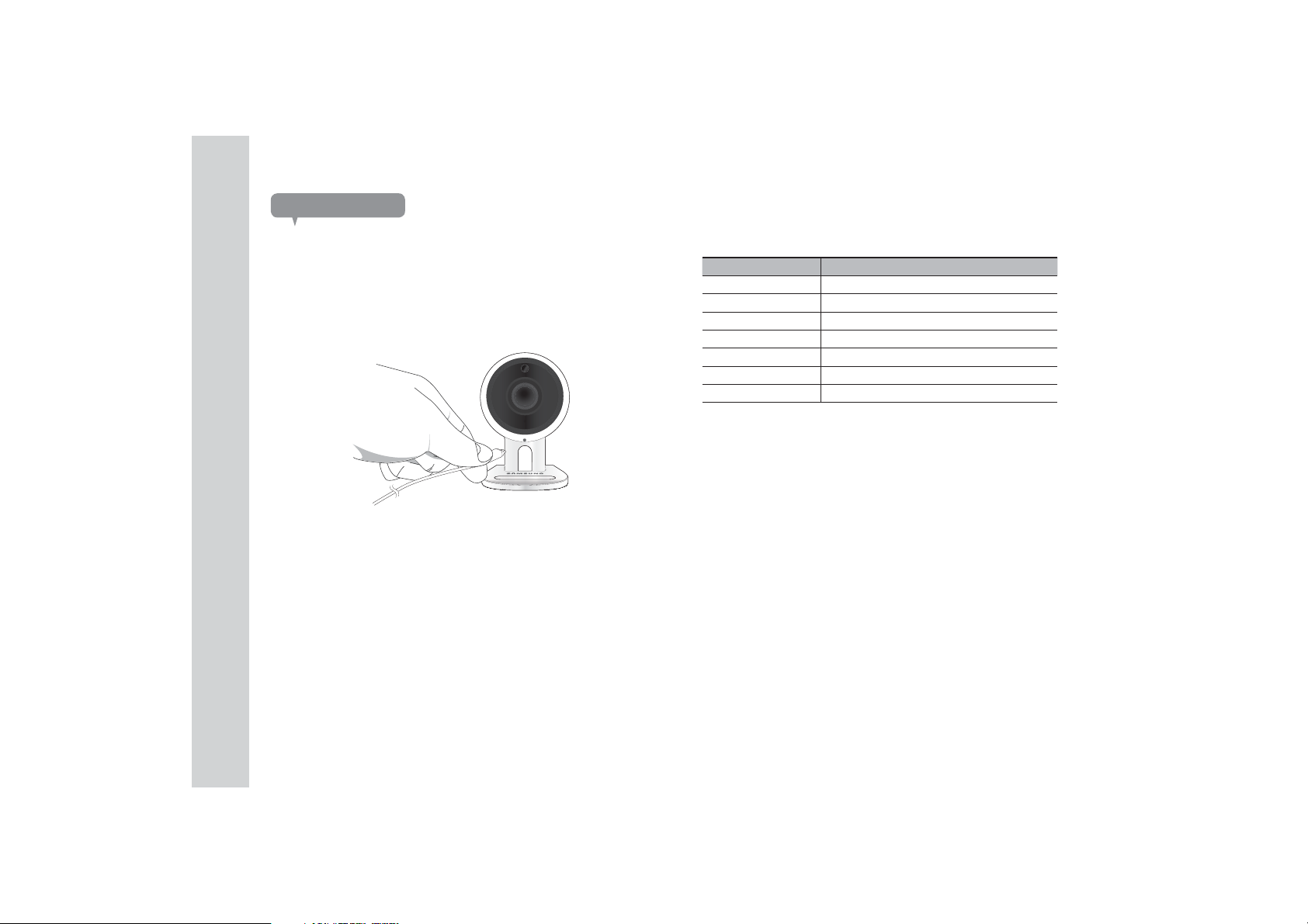
Power Supply
Plug-in the camera power adapter to the wall outlet and connect the camera as
shown.
`
Make sure to use the provided power adaptor. If you use an adaptor other than the
n
power supply adaptor provided in our package, the product may not operate properly.
` It takes about 30 seconds to reboot the camera completely.
` When the camera is turned on, the LED blinks red.
❖LED status
LED indicator shows operational status with colors.
Refer to table below for detailed meaning of the LED indicator.
Color Status
Red Booting up
Red Blinking Booting completed / Establishing network connection
Blue Blinking Connecting to the network.
Blue Local connection established
Green Connection to server completed / Normal operation
Yellow/Orange Waiting to connect with a wireless router
Purple Updating firmware
10
· English
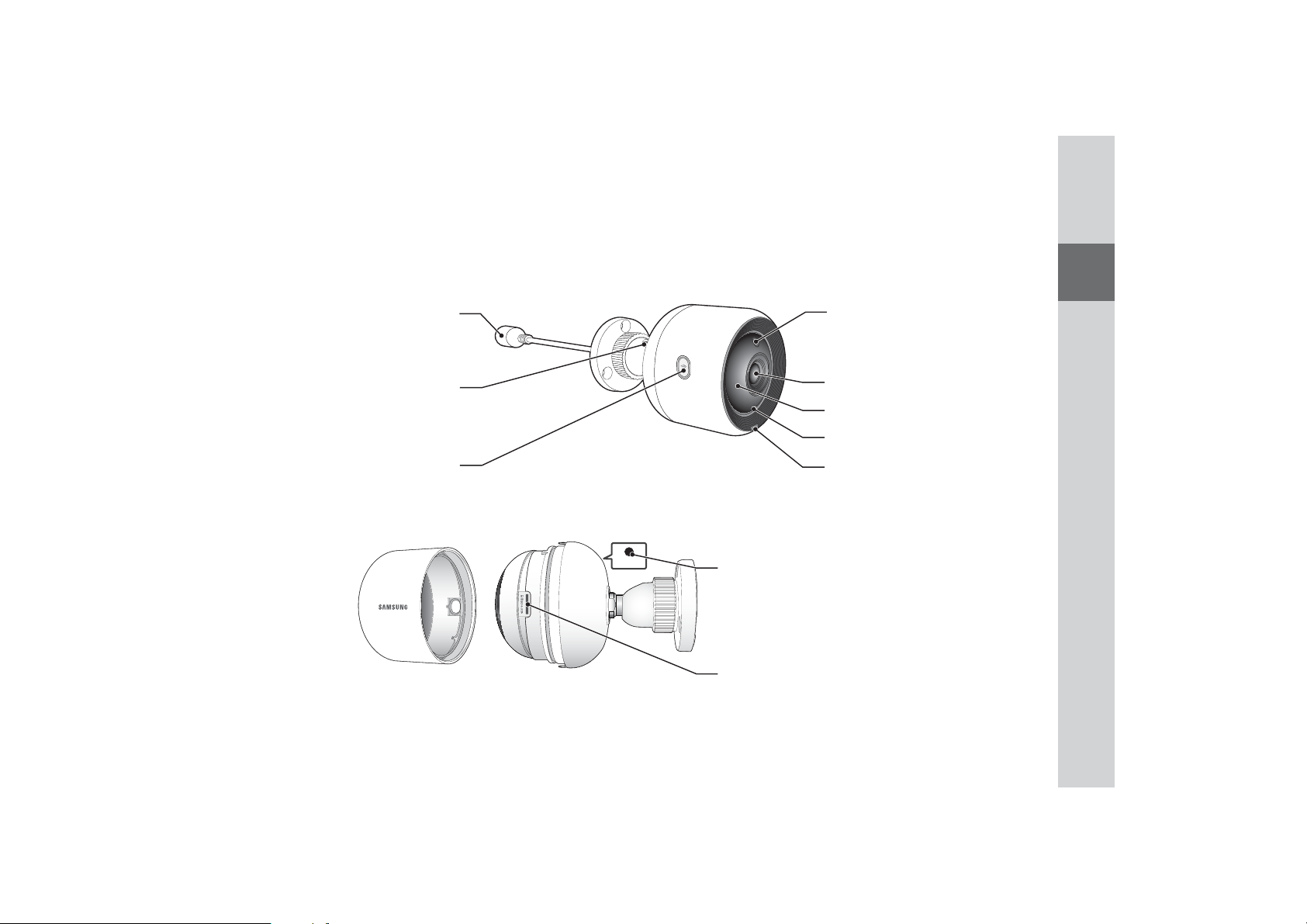
Part names and functions (SNH-V6430BNH)
01
The camera is connected with the PoE adapter to
connect with the power supply and the network.
Wi-Fi is used for wireless communication between
PoE connection port
Angle adjustment hinge
Wi-Fi Direct button
camera and smartphone.
5(6(7
Luminance Sensor
Detects light levels where the camera is placed.
Night vision mode changes according to detection
result.
Camera lens
Built-in IR LEDs for night vision
Built-in microphone
Power/Network status LED
Reset button
Resets the camera settings to the default.
The system restarts if you press the button for 10
seconds using a pointed object such as a needle.
` If you press too strongly, the button can break.
J
Micro card insertion hole
Getting Started
11
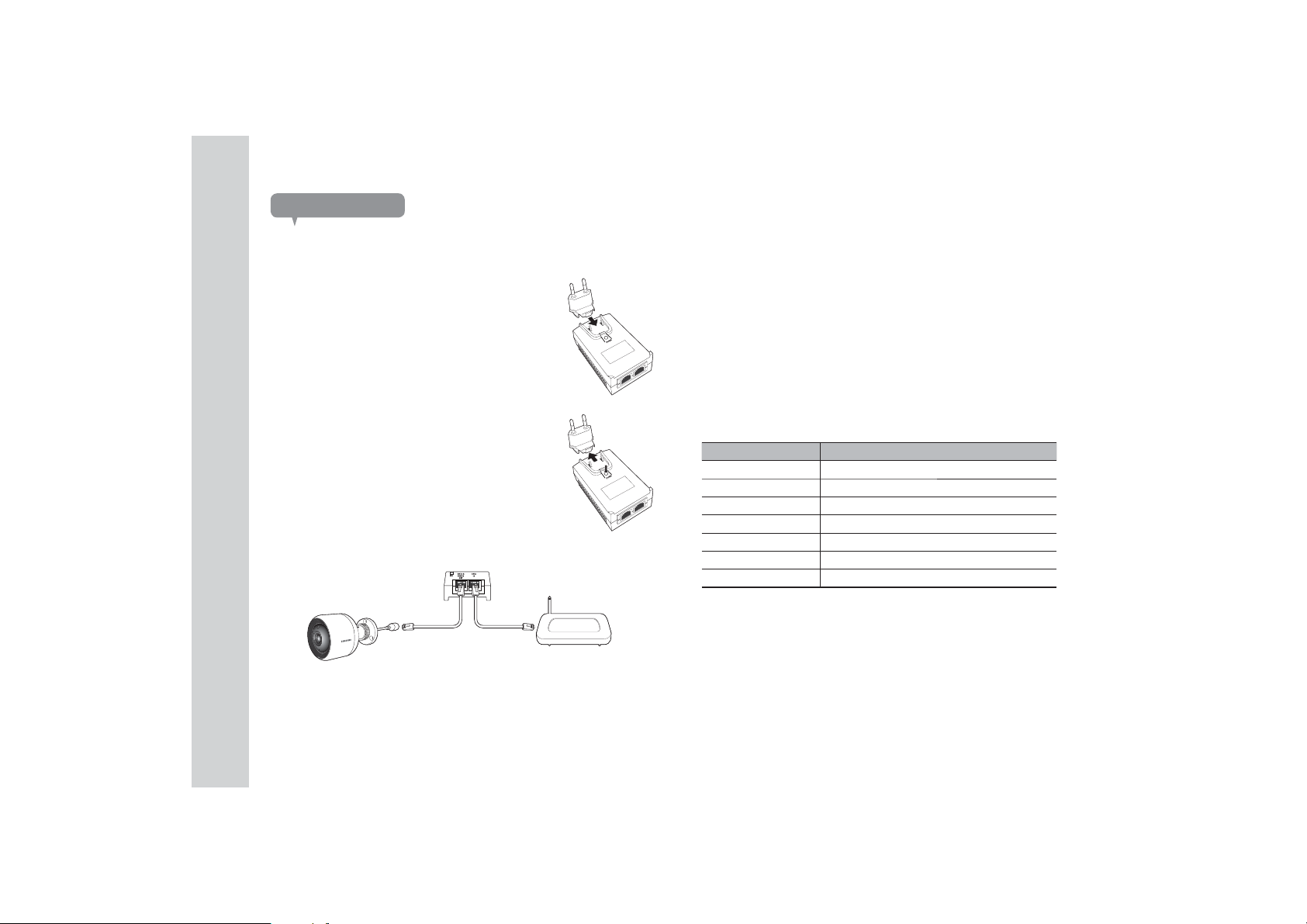
Power Supply
Using the PoE adapter
1.
Push to insert the included PoE adapter in the power
plug, as shown in the figure below.
2. To remove the power plug from the PoE adapter,
press the [PUSH] section as shown in the figure
below, and push up the power plug.
Connect the LAN cable from the PoE adapter [DATA & POWER OUT]
3.
socket to the PoE socket.
4. Connect the LAN cable from the PoE adapter [DATA I N ] socket to the LAN
port of the router.
`
When connecting the camera wirelessly via Wi-Fi Direct, remove the LAN cable
n
connecting the PoE adapter and the router.
5.
Plug the PoE adapter into an electrical outlet.
` Use the PoE adapter and power plug that have been included with the camera. Using
n
an incompatible adapter may cause the camera to malfunction.
`
It takes about 30 seconds to reboot the camera completely.
`
When the camera is turned on, the LED blinks red.
❖LED status
LED indicator shows operational status with colors.
Refer to table below for detailed meaning of the LED indicator.
Color Status
Red Booting up
Red Blinking Booting completed / Establishing network connection
Blue Blinking Connecting to the network.
Blue Local connection established
Green Connection to server completed / Normal operation
Yellow/Orange Waiting to connect with a wireless router
Purple Updating firmware
12
· English
<Router>
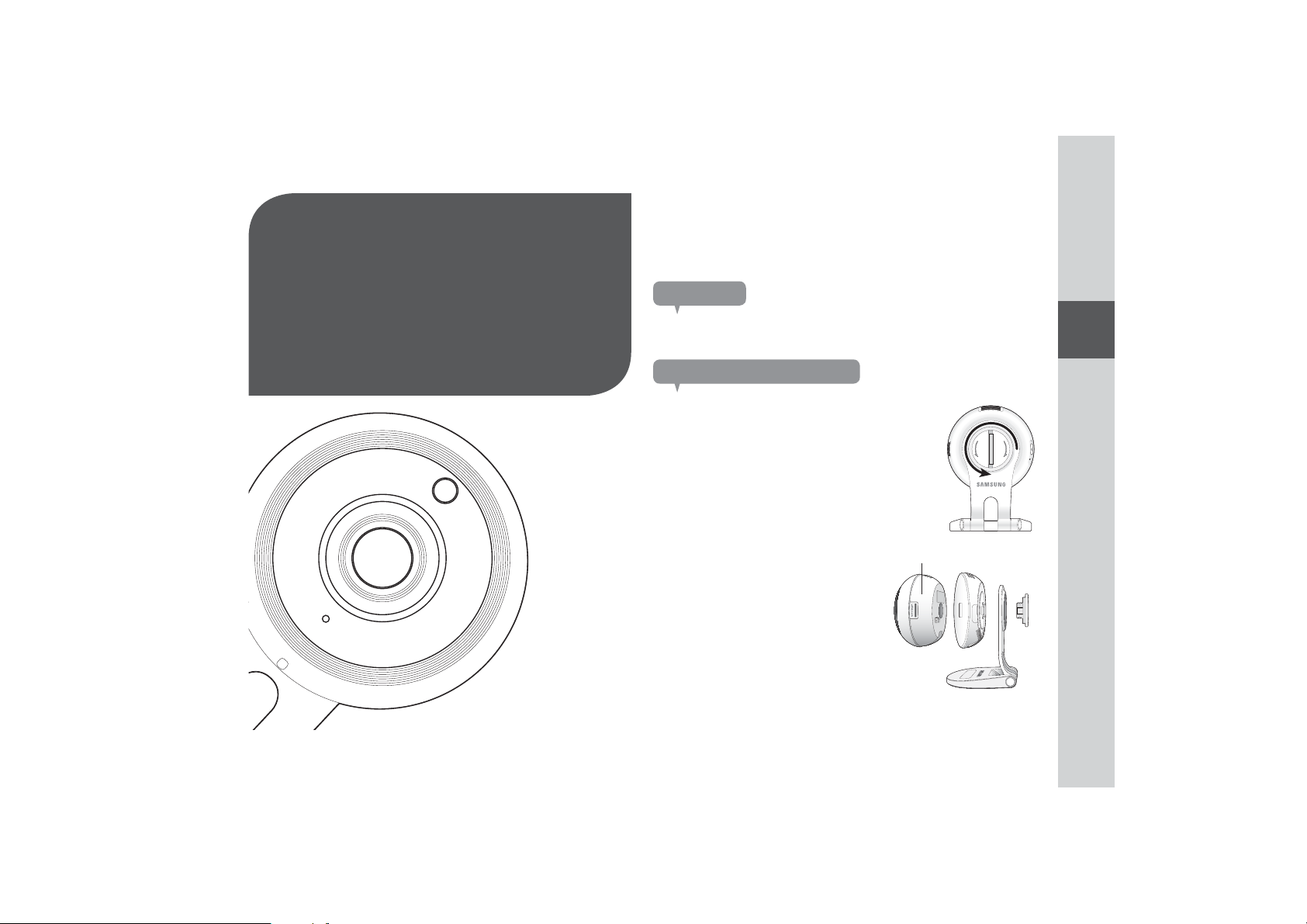
Indoor/Outdoor bracket
switching
Precautions
I
NSTALLATION
N
ETWORK
C
13 Indoor/Outdoor bracket
switching
13 Precautions
13 Separating the indoor bracket
14 Installing the outdoor bracket
14 Installation
(SNH-V6430BN)
14 Precautions
14 Installing on the wall and
ceiling using screws
15 Adjusting the camera angle
16 Installation
(SNH-V6430BNH)
16 Precautions
16 Installing on the wall and
ceiling using screws
17 Adjusting the camera angle
&
ONNECTION
02
18 Network Connection and
Settings (SNH-V6430BN)
18 Precautions
18 Connection using the Wi-Fi
Direct function
19
Network Connection and
Settings (SNH-V6430BNH)
19 Precautions
19 Connecting via network cable
20 Connection using the Wi-Fi
Direct function
1. Outdoor bracket is available separately.
Separating the indoor bracket
1.
Turn the knob on the back of the camera in the
[LOOSEN] direction.
2. Remove the bracket from the main body
of the camera, as shown in the figure
below.
Main body
02
Installation & Network Connection
7
,
*
1
(
+
6
7
2
(
1
2
/
5(6(7
13
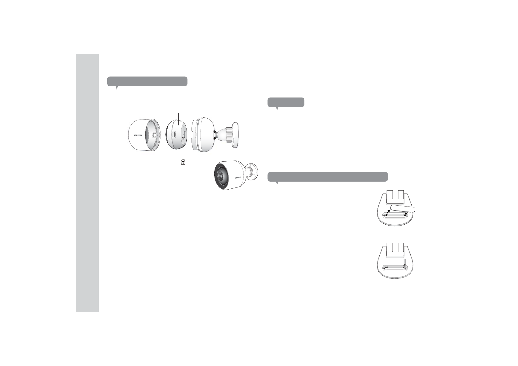
Installing the outdoor bracket
1.
Install the outdoor bracket into the groove on the main body of the camera,
as shown in the figure below.
Main body
2.
Turn the housing to the LOCK [ ] direction.
Installation (SNH-V6430BN)
Precautions
1. Install the camera in a location with a good Wi-Fi signal and no interference.
2. Keep it away from humidity such as around the humidifier.
Keep it away from direct sunlight, strong light or dust; install it in a place with
3.
clear view.
4. Do not install it in a place where there are a lot of obstacles.
5. Keep the lens clean at all times.
Wipe off the dust with a soft cloth.
Installing on the wall and ceiling using screws
1. Remove the rubber packing attached to the
camera stand.
2. Take out the screws (M3xL20) and anchors
(Φ5x25mm).
When installing on a wooden wall
3. Fix the bracket to the wall using screws, as
shown in the next image. Using a Phillips
screwdriver, fasten screws in 2 screw holes on
the wall on which the camera is to be installed.
14
· English
 Loading...