

Hantek DSO4072, DSO4202, DSO4102 User Manual

DSO4000 Series
Digital Storage Oscilloscope
User Manual
(Version 1.2)

Contents
Safety Tips ....................................................................................................................................... 1
General Safety Summary .................................................................................................................... 1
Safety Terms and Symbols .................................................................................................................. 2
Product Scrapping ............................................................................................................................... 2
Brief Introduction to DSO4000 Series ................................................................................................. 3
Chapter 1 Introduction ............................................................................................................... 4
1.1 Accidence of front panel and the user interface ....................................................................... 1
1.1.1 Front Panel ....................................................................................................................... 1
1.1.2 User Interface ................................................................................................................... 2
1.2 Functional Check ...................................................................................................................... 3
1.2.1 Power on the oscilloscope ................................................................................................ 3
1.2.2 Connect the oscilloscope .................................................................................................. 3
1.2.3 Observe the waveform ...................................................................................................... 4
1.3 Probe Examination ................................................................................................................... 4
1.3.1 Safety ................................................................................................................................ 4
1.3.2 Use of Probe Check Wizard ............................................................................................. 5
1.3.3 Manual Probe Compensation ........................................................................................... 5
1.3.4 Probe Attenuation Setting ................................................................................................. 6
1.4 Self Calibration ......................................................................................................................... 6
Chapter 2 Main Feature Description ........................................................................................ 7
2.1 Menu and control keys ............................................................................................................. 7
2.2 Multi-functional Knobs and Buttons .......................................................................................... 8
2.3 Signal Connectors .................................................................................................................... 8
2.4 Oscilloscope Setup ................................................................................................................... 9
2.5 Default setups .......................................................................................................................... 9
2.6 Horizontal System ................................................................................................................... 11
2.6.1 Horizontal control knob ................................................................................................... 12
2.6.2 Display Scan mode ......................................................................................................... 14
2.7 Vertical System ....................................................................................................................... 15
2.7.1 Vertical Controls .............................................................................................................. 15
2.7.2 Math FFT ........................................................................................................................ 16
2.8 Trigger System ....................................................................................................................... 22
2.8.1 Trigger Controls .............................................................................................................. 23
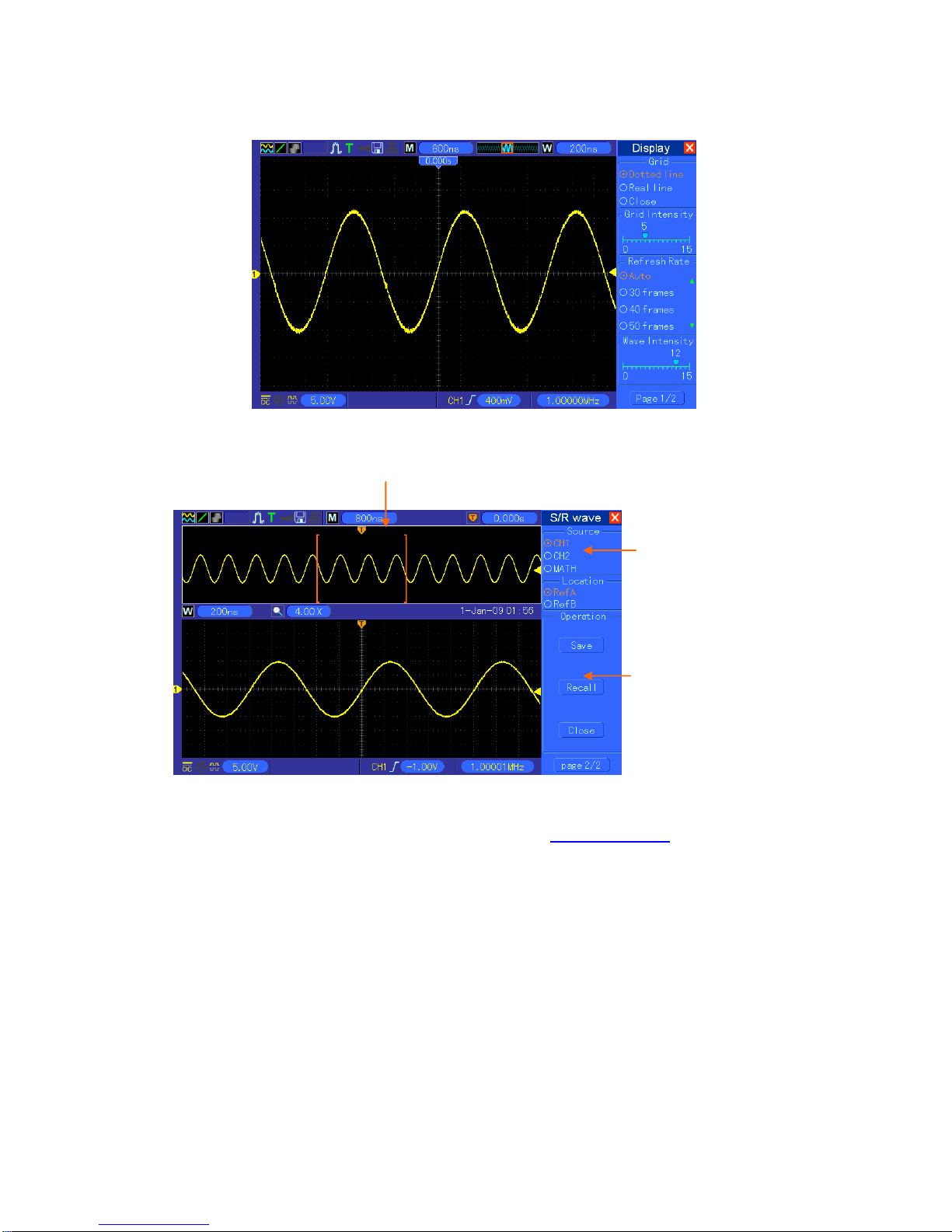
2.9 Save/Recall ............................................................................................................................ 29
2.10 Display System ....................................................................................................................... 31
2.10.1 XY Format ....................................................................................................................... 32
2.11 Measure System .................................................................................................................... 32
2.11.1 Scale measurement ........................................................................................................ 32
2.11.2 Cursor measurement ...................................................................................................... 32

2.11.3 Measurement .................................................................................................................. 35
2.12 Acquisition System ................................................................................................................. 37
2.13 UTILITY System ..................................................................................................................... 39
2.13.1 Firmware Update ............................................................................................................ 39
2.13.2 Self Calibration ............................................................................................................... 40
2.13.3 Keypad Beep Control ...................................................................................................... 40
2.13.4 Language ........................................................................................................................ 40
2.13.5 GUI Color Setting ............................................................................................................ 40
2.13.6 Time Setting .................................................................................................................... 40
2.13.7 System Status ................................................................................................................. 40
2.13.8 Pass/fail .......................................................................................................................... 40
2.13.9 Recorder ......................................................................................................................... 42
2.13.10 Filter ............................................................................................................................ 43
2.13.11 Wave ........................................................................................................................... 43
2.13.12 DDS............................................................................................................................. 43
2.13.13 DVM ............................................................................................................................ 44
2.14 Help System ........................................................................................................................... 44
2.15 Fast Action Buttons ................................................................................................................ 45
2.15.1 Autoset ............................................................................................................................ 45
2.16 Waveform Generator and Power Amplifier ............................................................................. 47
2.16.1 Waveform Generator ...................................................................................................... 47
2.16.2 Power Amplifier(Optional) ............................................................................................... 51
Chapter 3 Application Examples ............................................................................................ 53
3.1 Example 1: Taking Simple Measurements ............................................................................. 53
3.2 Example 2: Taking Cursor Measurements ............................................................................. 54
3.3 Example 3: Analyzing Input Signals to Eliminate Random Noise .......................................... 57
3.4 Example 4: Capturing Single-shot Signal ............................................................................... 59
3.5 Example 5: Using X-Y Mode .................................................................................................. 59
3.6 Example 6: Triggering on Pulse Width ................................................................................... 61
3.7 Example 7: Triggering on Video Signal .................................................................................. 62
3.8 Example 8: Using Slope Trigger to Capture Particular Slope Signal ..................................... 63
3.9 Example 9: Using Overtime Trigger to Measure Long Pulse Signal ...................................... 64
3.10 Example 10: Using Math Functions to Analyze Waveforms .................................................. 65
3.11 Example 11: Measuring Data Propagation Delay .................................................................. 66
Chapter 4 Troubleshooting ..................................................................................................... 68
4.1 Problem Settlement ................................................................................................................ 68
Chapter 5 Specifications ......................................................................................................... 69
5.1 Technical Specifications ......................................................................................................... 69
5.2 Accessories ............................................................................................................................ 75
Chapter 6 General Care and Cleaning ................................................................................... 76
6.1 General Care .......................................................................................................................... 76

6.2 Cleaning ................................................................................................................................. 76
Appendix A Harmful and Poisonous Substances or Elements ............................................... 77

Safety Tips
General Safety Summary
Read the following safety precautions to avoid injury and prevent damage to this product or any
products connected to it. To evade potential hazards, use this product only as specified.
Only qualified personnel should perform maintenance.
Avoid fire or personal injury.
Use suitable power cord. Use only the power cord specified for this product and certified for the
country of use.
Connect and disconnect properly. Connect a probe with the oscilloscope before it is connected
to measured circuits; disconnect the probe from the oscilloscope after it is disconnected from
measured circuits.
Ground the product. This product is grounded through the grounding conductor of the power
cord. To avoid electric shock, the grounding conductor must be connected to earth ground. Before
making connections to the input or output terminals of the product, ensure that the product is
properly grounded.
Connect the probe in a right way. The probe ground lead is at ground potential. Do not connect
the ground lead to an elevated voltage.
Check all terminal ratings. To avoid fire or shock hazard, check all ratings and markings on the
product. Refer to the product manual for detailed information about ratings before making
connections to the product.
Do not operate without covers. Do not operate this product with covers or panels removed.
Avoid exposed circuitry. Do not touch exposed connections and components when power is
present.
Do not operate with suspected failures. If you suspect there is damage to this product, have it
inspected by qualified service personnel.
Assure good ventilation.
Do not operate in wet/damp environments.
Do not operate in an explosive atmosphere.
Keep product surfaces clean and dry.
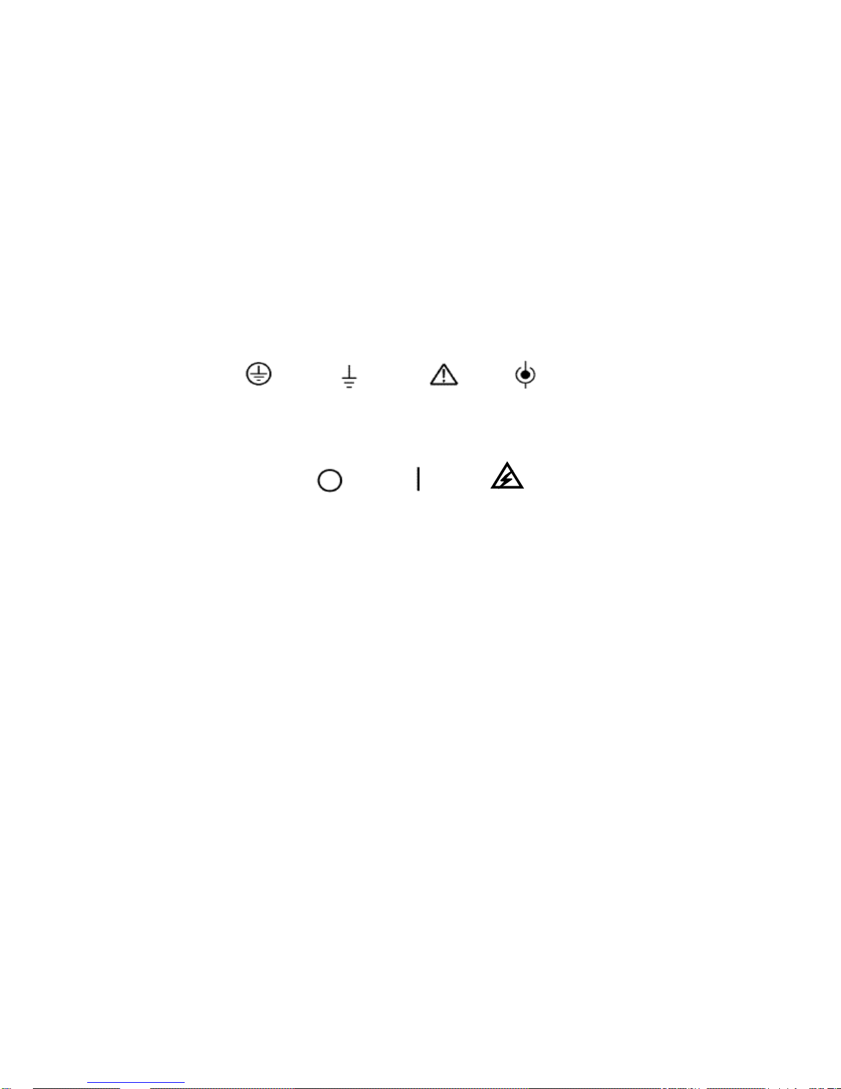
Safety Terms and Symbols
Terms on Product
The following terms may appear on the product:
DANGER indicates an injury hazard immediately accessible as you read the marking.
WARNING indicates an injury hazard not immediately accessible as you read the marking.
CAUTION indicates a possible hazard to this product or other property.
Symbols on Product
The following symbols may appear on the product:
Product Scrapping
Device Recycling
We need extract and utilize natural resources to produce this device. If you do not reclaim the
device in a proper way, some substances it contains may become harmful or poisonous to
environments or human bodies. To avoid them being released outside and to minimize the waste
of natural resources, we suggest you reasonably call back this device to ensure proper recovery
and recycling of most materials within it.
Mains
Disconnected
OFF (Power)
Mains
Connected
ON (Power)
High Voltage
Protective
Ground
(Earth)
Terminal
Measurement
Ground
Terminal
CAUTION
Refer to Manual
Measurement
Input Terminal

Brief Introduction to DSO4000 Series
DSO4000 Series oscilloscopes cover the bandwidths from 70MHz to 200MHz, and provide
the real-time and equivalent sample rates respectively up to 1GSa/s and 25GSa/s. In addition,
they have 7 inch color TFT LCD as well as WINDOWS-style interfaces and menus for easy
operation.
What’s more, the plenty menu information and the easy-to-operate buttons allow you to gain
information as much as possible in measurement; the multifunctional knobs and the powerful
shortcut keys help you save a lot of time in operation; the Autoset function lets you detect sine and
square waves automatically; the Probe Check Wizard guides you to adjust the probe
compensation and set the Probe option attenuation factor. By using the three methods the
oscilloscope provides (context-sensitive, hyperlinks, and an index), you may master all operations
on the device in quite a short time so as to greatly improve your efficiency in production and
development.
Model
Channels
Bandwidth
Sample Rate
LCD
DSO4072
2
70MHz
1GS/s
7 inch color
DSO4102
2
100MHz
1GS/s
7 inch color
DSO4202
2
200MHz
1GS/s
7 inch color
Model List of DSO4000 Series

Chapter 1 Introduction
Accidence of front panel and the user interface
Functional Check
Probe Examination
Self Calibration
DSO4000 Series Digital Storage Oscilloscope 1
1.1 Accidence of front panel and the user interface
This section will make you understand the front operation panel of this series of digital oscilloscope
at first before use.
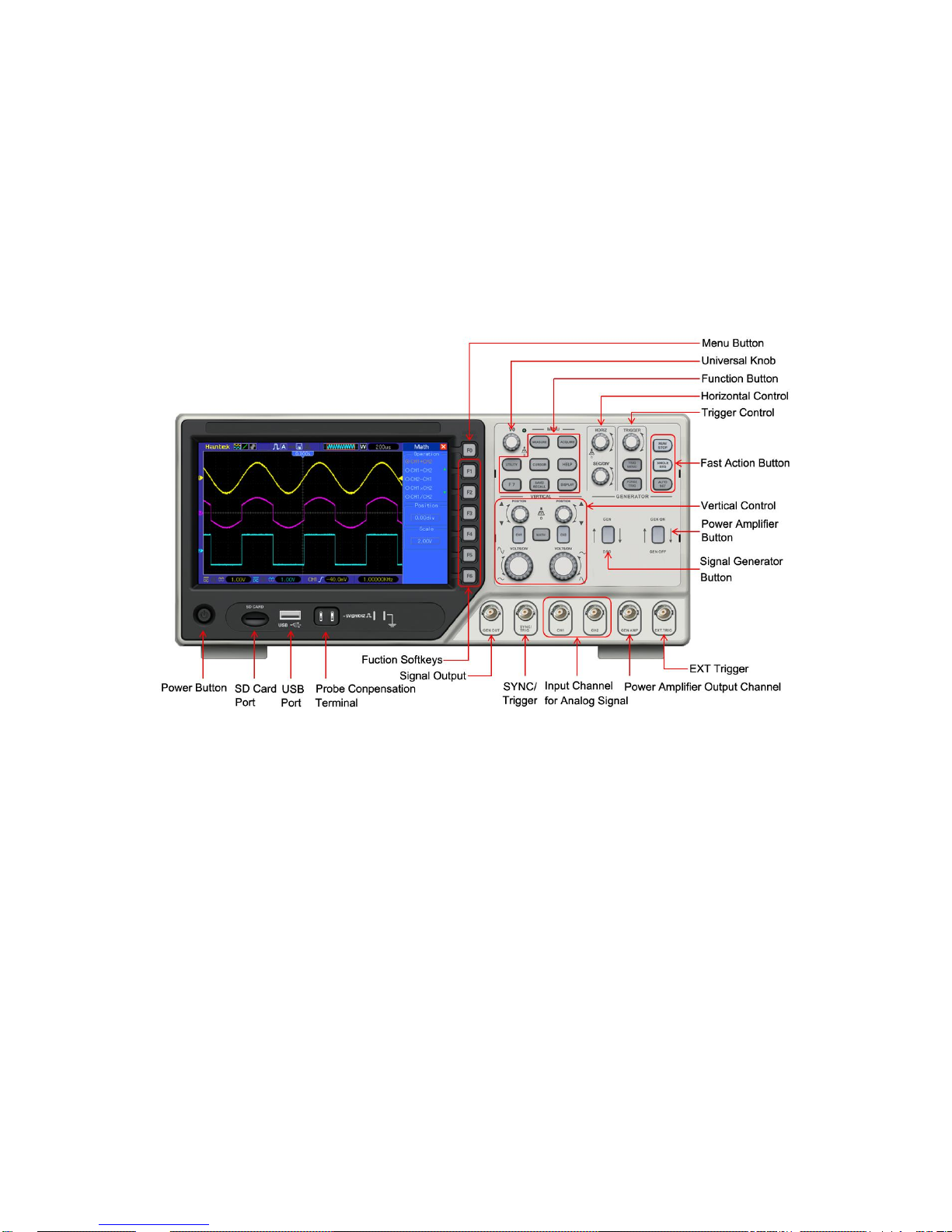
1.1.1 Front Panel
The content below simply describes and introduces the front panel and the back part of this series
of digital oscilloscope so that you can get familiar with this series of digital oscilloscope well within
the shortest time.
Figure 1-1 Figure of Front Panel
DSO4000 Series Digital Storage Oscilloscope 2
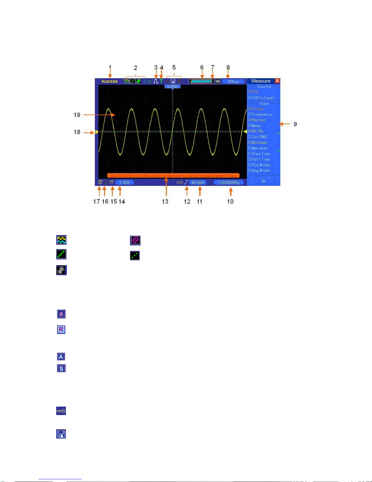
1.1.2 User Interface
1. Hantek mark
2. Display Format:
3. Acquisition Mode: Normal, Peak Detect or Average
4. Trigger Status:
The oscilloscope is acquiring pretriggered data.
All pretriggered data have been acquired and the oscilloscope is ready to accept a trigger.
T The oscilloscope has detected a trigger and is acquiring the posttrigger information.
The oscilloscope works in auto mode and is acquiring waveforms in the absence of triggers.
The oscilloscope is acquiring and displaying waveform data continuously in scan mode.
● The oscilloscope has stopped acquiring waveform data.
S The oscilloscope has finished a single sequence acquisition.
5. Tool Icon:
: If this icon lights up, it means the keyboard of the oscilloscope is locked by the host computer
via USB control.
: If this icon lights up, it means the USB disk has been connected.
: YT
: Vectors
: Gray indicates auto persistence; Green means persistence display is enabled. When
the icon is set to green, the time for persistence display will be shown behind it.
: XY
: Dots

DSO4000 Series Digital Storage Oscilloscope 3
: This icon lights up only when the USB slave interface is connected with the computer.
6. Main Time Base Window
7. Display of window’s position in data memory and data length.
8. Window Time Base
9. Operating Menu shows different information for different function keys.
10. Readout shows frequency count.
11. Readout points out horizontal waveform position
12. Trigger Type:
: Edge trigger on the rising edge.
: Edge trigger on the falling edge.
: Video trigger with line synchronization.
: Video trigger with field synchronization.
: Pulse Width trigger, positive polarity.
: Pulse Width trigger, negative polarity.
13. Pop-up Prompt
14. Readout tells trigger level.
15. Icon indicates whether the waveform is inverted or not.
16. 20M Bandwidth Limit. If this icon lights up, it means the bandwidth limit is enabled, otherwise
disabled.
17. Icon indicates channel coupling.
18. Channel Marker
19. Window displays waveform.
1.2 Functional Check
Follow the steps below to perform a quick functional check to your oscilloscope.
1.2.1 Power on the oscilloscope
Plug in the oscilloscope and press the ON/OFF button. Then push the “UTILITY ->F6 ->F6 ->
F6->DEFAULT” button. The default Probe option attenuation setting is 10X.
1.2.2 Connect the oscilloscope
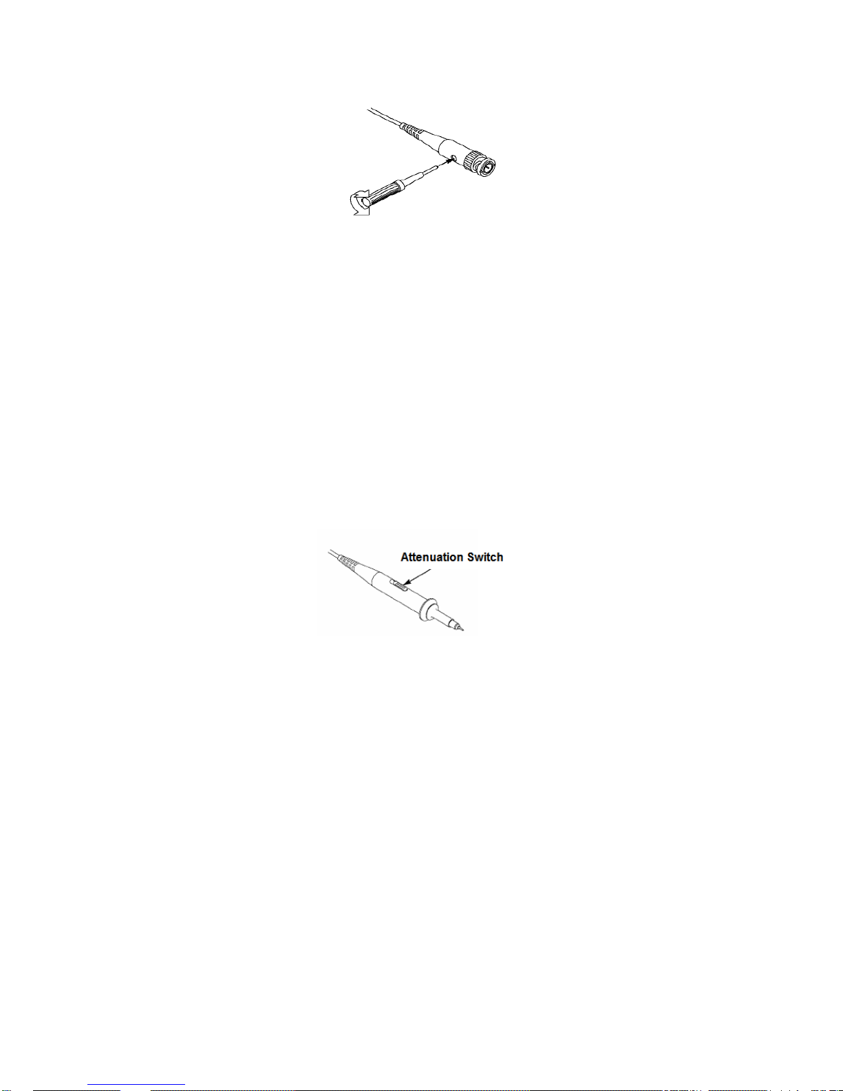
Set the switch on the probe to 10X and connect the probe to Channel 1 on the oscilloscope. First,
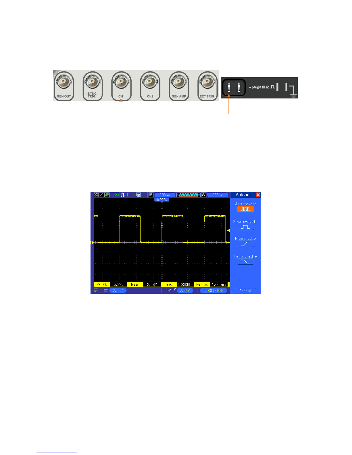
DSO4000 Series Digital Storage Oscilloscope 4
align the slot in the probe connector with the protuberance on the CH1 BNC and push to connect;
then, turn to right to lock the probe in place; after that, connect the probe tip and reference lead to
the PROBE COMP connectors. There is a mark on the panel: Probe COMP ~5V@1KHz.
1.2.3 Observe the waveform
Press the AUTOSET button and you should see within a few seconds a square wave of about 5V
peak-to-peak at 1kHz in the display. Press the CH1 MENU button twice to remove Channel 1.
Push the CH2 MENU button and repeat Step 2 and Step 3 to observe Channel 2.
1.3 Probe Examination
1.3.1 Safety
When using the probe, keep your fingers behind the guard on the probe body to avoid electric
shock. Do not touch metallic portions of the probe head while it is connected to a voltage source.
Connect the probe to the oscilloscope and connect the ground terminal to ground before you start
any measurements.
CH1: to connect with the probe
PROBE COMP

DSO4000 Series Digital Storage Oscilloscope 5
1.3.2 Use of Probe Check Wizard
Every time you connect a probe to an input channel, you should use the probe check wizard to
verify that this probe is operating correctly.
Use the vertical menu (for example, push the CH1 MENU button) to set the Probe option
attenuation factor.
1.3.3 Manual Probe Compensation
Upon the first connection of a probe and an input channel, you should manually perform this
adjustment to match the probe to the input channel. Uncompensated or miscompensated probes
may lead to errors or faults in measurement. To adjust the probe compensation, follow the steps
below.
1. Set the Probe option attenuation in the channel menu to 10X. Set the switch on the probe to
10X and connect the probe to Channel 1 on the oscilloscope. If you use the probe hook-tip,
ensure it is firmly inserted onto the probe. Attach the probe tip to the PROBE COMP
~5V@1KHz connector and the reference lead to the PROBE COMP Ground connector.
Display the channel and then press the AUTOSET button.
2. Check the shape of the displayed waveform.
3. If necessary, use a nonmetallic screwdriver to adjust the variable capacity of your probe until
the shape of the waveform turns to be the same as the above figure. Repeat this step as
necessary. See the figure below for the way of adjustment.
Compensated correctly
Overcompensated
Undercompensated
DSO4000 Series Digital Storage Oscilloscope 6
1.3.4 Probe Attenuation Setting
Probes are of various attenuation factors which affect the vertical scale of the signal. The Probe
Check function is used to verify if the Probe attenuation option matches the attenuation of the
probe.
As an alternative method to Probe Check, you can push a vertical menu button (such as the CH 1
MENU button) and select the Probe option that matches the attenuation factor of your probe.
Make sure that the Attenuation switch on the probe matches the Probe option in the oscilloscope.
Switch settings are 1X and 10X.
When the Attenuation switch is set to 1X, the probe limits the bandwidth of the oscilloscope to
6MHz. To use the full bandwidth of the oscilloscope, be sure to set the switch to 10X.
1.4 Self Calibration
The self calibration routine helps optimize the oscilloscope signal path for maximum measurement
accuracy. You can run the routine at any time but should always run it if the ambient temperature
changes by 5℃ or more. For a more accurate calibration, please power on the oscilloscope and
wait for 20 minutes until it has adequately warmed up.
To compensate the signal path, disconnect any probes or cables from the front-panel input
connectors. Then, push the UTILITY button, select the Do Self Cal option and follow the directions
on the screen.

Basic Operation
Chapter 2 Main Feature Description
This chapter provides some general information that you need to learn before using an
oscilloscope. It contains:
Menu and Control Keys
Multi-functional Knobs and Buttons
Signal Connectors
Oscilloscope Setup
Default Setups
Default Setups
Horizontal System
Vertical System
Trigger System
Save and Recal
Display Syetem
Measure System
Acquisition System
Utility System
Help System
Fast Action Buttons
Waveform Generator and and Power Amplifier
Basic Operation
DSO4000 Series Digital Storage Oscilloscope 7
2.1 Menu and control keys
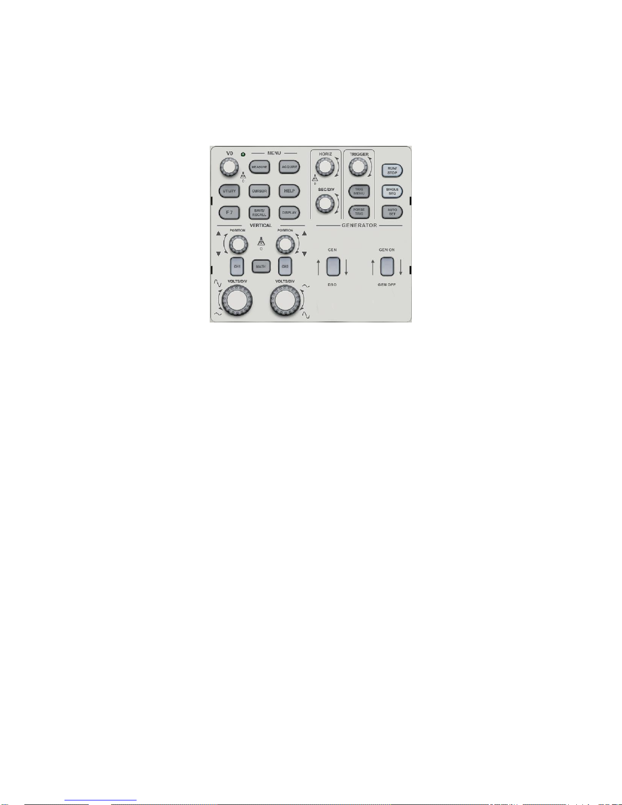
As shown in the figure below:
Figure2-1 Control keys
All the keys are described as follows:
[CH1], [CH2]: display setup menus of channel 1 and channel 2.
[MATH]: display “ARITHMETICAL OPERATION” and “REFERENCE WAVEFORM” menu.
[HORIZ]: display “HORIZONTAL” menu.
[TRIG]: display “TRIGGER” control menu.
[FORCE TRIG]: It is used for finishing acquisition of the current waveform no matter whether
the oscilloscope detects trigger, and it is mainly applied to “NORMAL” and “SINGLE” in the
trigger mode.
[SAVE/RECALL]: display the “SAVE/RECALL” menu of setups and waveform.
[MEASURE]: display the “MEASURE” menu.
[ACQUIRE]: display the “ACQUIRE” menu.
[UTILITY]: display “UTILITY FUNCTION” menu.
[CURSOR]: display the “CURSOR” menu. The [V0] knob can be used for regulating the
position of the cursor when the “CURSOR” menu is displayed and the cursor is triggered.
[DISPLAY]: show the “DISPLAY” menu.
[HELP]: enter the on-line help system.
[AUTOSET]: automatically set the control state of the oscilloscope so as to display suitable
waveform.
[RUN/STOP]: continuously acquire waveform or stop acquisition
[SINGLE SEQ]: Acquire a single trigger, finish acquisition and then stop.
[GEN DSO]: Waveform generator output button..
[GEN ON/GEN OFF]: Power Amplifier output button.
Basic Operation
DSO4000 Series Digital Storage Oscilloscope 8
2.2 Multi-functional Knobs and Buttons
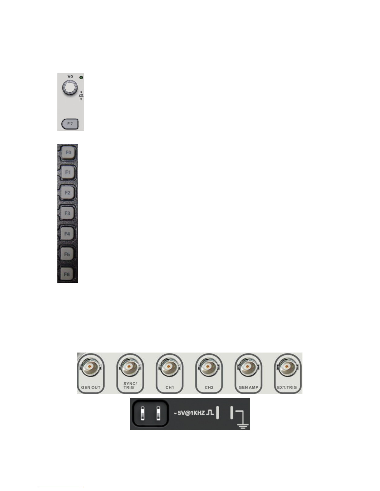
2.3 Signal Connectors
See the figure below to find the seven signals connectors and a pair of metal electrodes at the
bottom of the oscilloscope panel.
1. GEN OUT: Waveform Signal Output.
F0: Hide/Show button. Push it to hide the menu options on the right side of the
screen and give a full screen display of waveforms. Push it again to show the menu
options.
F1-F5: These five buttons are all multi-functional. They are in charge of selecting
corresponding menu options on the screen in different menu modes. For example, in
the UTILITY menu, F1-F5 respectively correspond to ‘System Info’ – ‘Advance’.
F6: This functional button is mainly used to turn pages and confirm a selection, such
as ‘next page’, ‘previous page’, and ‘press F6 to confirm’ appearing when you push
Self Calibration option.
V0: Multi-functional knob. Under different menu options, it supports selecting menu
options (MEASURE), moving cursors and levels (Slope Trigger).
Press this knob to reset data (trigger holdoff, overtime of the overtime trigger and
slope trigger), select menu options and so on. Easy to operate.
F7: Push this button in single-window mode to switch between dotted line display
and cross display. Push it in dual-window mode to perform autocruise.

Basic Operation
DSO4000 Series Digital Storage Oscilloscope 9
2. SYNC/TRIG: Output the Sync signal, or input trigger signal on DDS interface.
3. CH1, CH2: Input connectors for waveform display, through which to connect and input the
signal to be measured.
4. GEN AMP: Power amplifier output.
5. EXT.TRIG: Input connector for an external trigger source, though with to connect and input
the external trigger signal.
6. Probe Compensation: Voltage probe compensation output and ground, used to electrically
match the probe to the oscilloscope input circuit. The probe compensation ground and BNC
shields connect to earth ground and are considered to be ground terminals. To avoid
damages, do not connect a voltage source to any of these ground terminals.
2.4 Oscilloscope Setup
While operating the oscilloscope, you may often use three features: Autoset, saving a setup and
recalling a setup. Hereinafter they are introduced one by one.
Autoset: This function can be used to adjust the horizontal and vertical scales of the oscilloscope
automatically and set the trigger coupling, type, position, slope, level and mode, etc., to acquire a
stable waveform display.
Saving a Setup: By default, the oscilloscope will save the setup each time before being closed,
and automatically recall the setup once being turned on. (Note: If you modify the setup, please
wait for more than 5 seconds before turning off the oscilloscope to ensure the proper
storage of new settings.) You can save 10 settings permanently in the oscilloscope and reset
them as necessary.
Recalling a Setup: The oscilloscope can recall any of your saved setups or the default factory
setup.
Default Setup: The oscilloscope is preset for normal operations when it is shipped from the
factory. This is the default setup. You may recall this setup at any time for your requirements.
2.5 Default setups
The default setups represent some option parameters that are set before the oscilloscope leaves
factory for normal operations.
When you push “UTILITY->Default” button, the oscilloscope will display the CH1 waveform and
remove all the others. The table below gives the options, buttons and controls that change settings
at default setup.
Menu or System
Option, Button or Knob
Default Setting
Acquire
(Three mode options)
Normal
Averages
16
Run/Stop
Run

Basic Operation
DSO4000 Series Digital Storage Oscilloscope 10
Cursor
Type
Off
Source
CH1
Horizontal (amplitude)
±3.2div
Vertical (time)
±4div
Display
Type
Vectors
Persist
Off
Format
YT
Horizontal
Window Mode
Single-window
Trigger Knob
Level
Position
0.00s
SEC/DIV
200μs
Math
Operation
—
Source
CH1-CH2
Position
0div
FFT
Vertical Scale
20dB
FFT Operation
Source
CH1
Window
Hanning
FFT Zoom
X1
Measure
Source
CH1
Type
None
Trigger (Edge)
Type
Edge
Source
CH1
Slope
Rising
Mode
Auto
Coupling
DC
Level
0.00v
Trigger (Video)
Polarity
Normal
Sync
All lines
Standard
NTSC
Trigger (Pulse)
When
=
Set Pulse Width
1.00ms
Polarity
Positive
Mode
Auto
Coupling
DC
Trigger (Slope)
Slope
Rising
Mode
Auto
Coupling
DC
When
=
Trigger (Swap)
CH1
Type
Edge
Slope
Rising
Mode
Auto

Basic Operation
DSO4000 Series Digital Storage Oscilloscope 11
Coupling
DC
Level
0.00v
CH2
Type
Edge
Slope
Rising
Mode
Auto
Coupling
DC
Level
0.00v
Trigger (OT)
Source
CH1
Polarity
Positive
Mode
Auto
Time
20ns
Vertical System,
All Channels
Coupling
DC
Bandwidth Limit
Unlimited
VOLTS/DIV
Coarse
Probe
Voltage
Voltage Probe Attenuation
10X
Invert
Off
Position
0.00div (0.00V)
VOLTS/DIV
1.00V
The following settings do not change when you push the DEFAULT SETUP button.
Language Option
Saved Settings
Saved Reference Waveforms
Display Contrast
Calibration Data
2.6 Horizontal System
Use the horizontal controls to change the horizontal scale and position of waveforms. The
horizontal position readout shows the time represented by the center of the screen, using the
trigger time as zero. When you change the horizontal scale, the waveform will expand or contract
to the screen center. The readout near the upper right of the screen shows the current horizontal
position in second. W indicates ‘Window Time Base’. The oscilloscope also has an arrow icon at
the top of the graticule to indicate the horizontal position.
Basic Operation
DSO4000 Series Digital Storage Oscilloscope 12
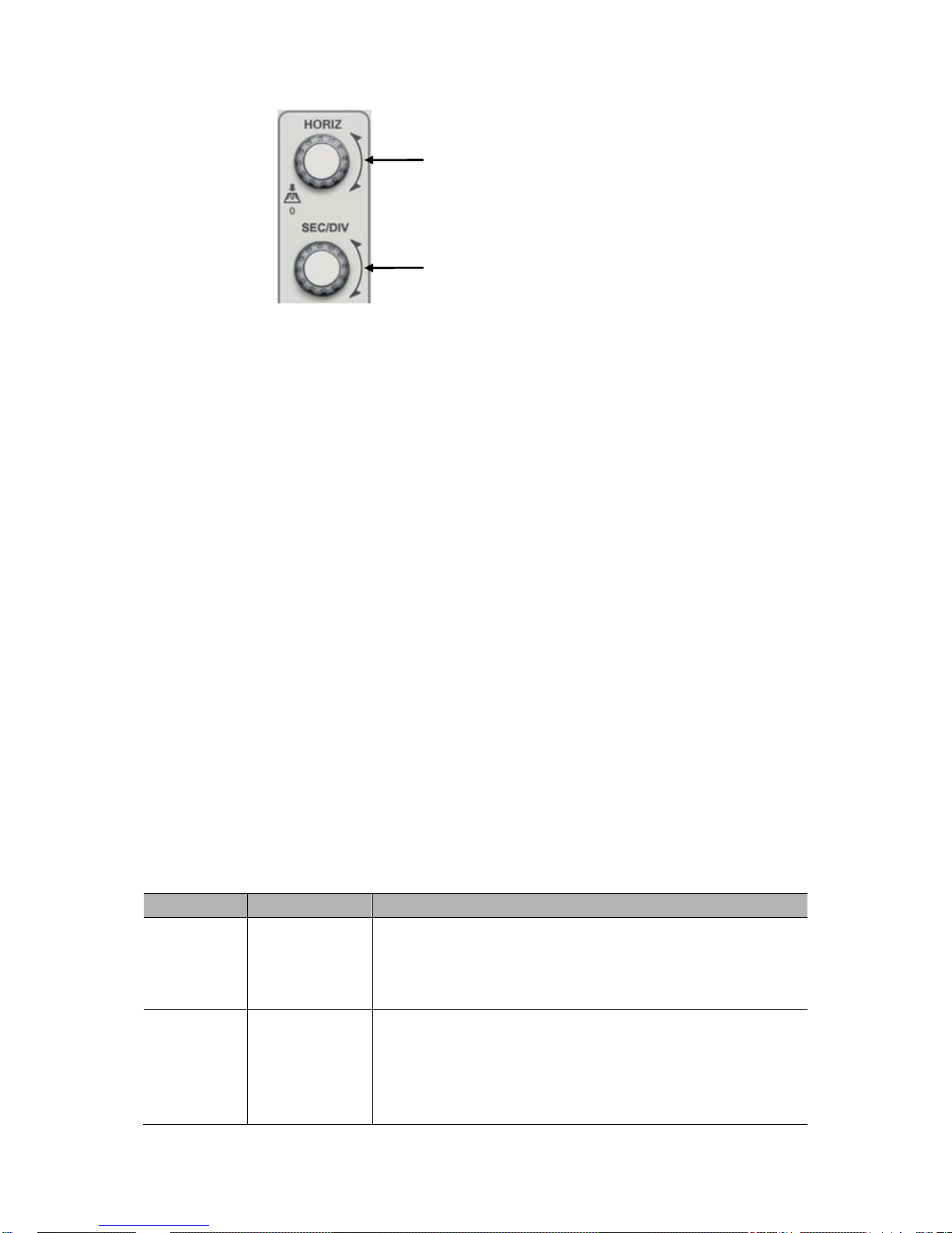
2.6.1 Horizontal control knob
The horizontal knob [SEC/DIV] changes the horizontal scale (time base), and the [POSITION]
knob changes the horizontal position (triggered displacement) triggered in the internal memory.
The center of the screen in the horizontal direction is a time reference point of the waveform.
Change of the horizontal scale will cause expansion or contraction of the waveform relative to the
center of the screen, while the change of the horizontal position is relative to the position of a
trigger point.
Horizontal POSITION knob
1. Regulate the horizontal position (trigger the position relative to the center of the display screen)
of the waveform (including MATH). The resolution of this control knob is changed according to
the time base.
2. Use the press down function of this knob to make the horizontal displacement return to zero,
namely back to the central position of the screen.
[SEC/DIV] knob
1. The knob is used for changing the horizontal time scale so as to conveniently observe the most
suitable waveform.
2. The knob is used for regulating the main time base. When the window expansion mode is
adopted, the knob is used for changing the expansion time base so as to change the window
width.
Each option in HORIZ MENU is described as follows.
Press [SEC/DIV] key to display the horizontal menu “HORI MENU”, and window expansion can be
implemented at this menu.
Options
Settings
Comments
Window
Control
Major Window
Minor Window
Selects the major or minor window in dual-window mode. The
window is highlighted once selected. Press this option button
in single-window mode to enter the daul-window mode.
Mark
Right arrow
Left arrow
Set/Clear
Clear All
This function is usable only in dual-window mode. It sets
marks at some waveform record locations that users are
interested in, and searches for these marks by right and left
arrows. Then it positions the window to this mark for further
observation.
HORIZONTAL POSITION Knob
SEC/DIV

Basic Operation
DSO4000 Series Digital Storage Oscilloscope 13
Page2/2
Holdoff
None
Select this menu and turn the multi-functional knob to adjust
the trigger holdoff time within the range of 100ns-10s. Select
this menu and push the multi-functional knob to reset the
holdoff time with the starting value 100ns.
Autoplay
None
This function is usable in dual-window mode. Push this menu
button and auto move it from left to right at a specified speed.
In the expanded window will display corresponding
waveforms until it stops once reaching the rightmost side of
the major scan window.
Time/Div
Coarse
Fine
Horiz
Position
Coarse
Fine
Window expansion
Window expansion is used for amplifying a segment of waveform so as to check details. The
window expansion time base setup cannot be slower than the setup of the main time base. In the
window expansion region, a selection region can be moved leftwards and rightwards by the
horizontal [POSITION] knob or enlarged and reduced by revolving the [SEC/DIV] knob. The
window expansion time base has higher resolution relative to the main time base. The smaller the
window expansion time base is, the higher the horizontal expansion multiple of the waveform is.
Carry out the following steps to observe details of local waveform:
1. Press [HORI MENU] to display the “HORIZON” menu.
2. Press “Window Ctr” menu.
3. Revolve [SEC/DIV] (to regulate the size of the window) and the horizontal [POSITION] (to
regulate the position of the window) to select the window of the waveform to be observed. The
expansion time base cannot be slower than the main time base.
Press the “Minor Window” button after the window is setting well.
Basic Operation
DSO4000 Series Digital Storage Oscilloscope 14
Single-window Mode
Dual-window Mode (Full Screen)
Notes:
1. For more information of the trigger holdoff, see Trigger Controls.
2. In single-window mode, press F0 to hide or show the menus on the right side. The
dual-window mode does not support the menu hiding function.
2.6.2 Display Scan mode
When the time base is set to be 80ms/div or more slowly and the trigger mode is set to “Auto”, the
oscilloscope enters the scan mode. At this mode, waveform display is renewed from left to right. At
the mode, no waveform trigger or horizontal position control exist. The channel coupling should be
set as direct current when a low-frequency signal is observed at the scan mode.
Major Window
Minor Window
(Expanded Window)
Location of expanded window data in memory
Basic Operation
DSO4000 Series Digital Storage Oscilloscope 15
2.7 Vertical System
2.7.1 Vertical Controls
Vertical controls can be used to display and remove waveforms, adjust vertical scale and position,
set input parameters and perform math calculations. Each channel has a separate vertical menu
to set. See below for menu description.
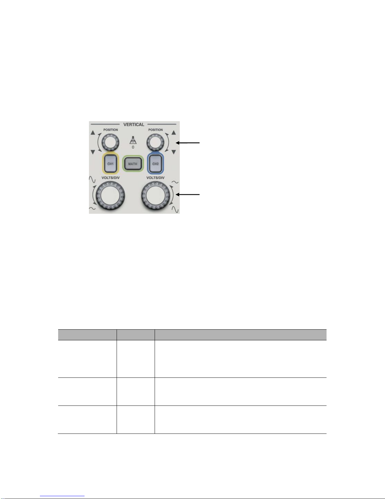
1. VERTICAL POSITION Knob
Move the channel waveform up and down on the screen. In dual-window mode, move the
waveforms in both windows at the same time in a same direction. Push this knob to return
waveforms to the vertical center position on the screen. Two channels correspond to two knobs.
2. VOLT/DIV Knob
Control the oscilloscope to magnify or attenuate the source signal of the channel waveform. The
vertical size of the display on the screen will change (increase or decrease) to the ground level.
Also you may use this knob to switch between coarse and fine.
3. Menu (CH1, CH2): Display vertical menu options; turn on or off the display of channel
waveforms.
Options
Settings
Comments
Coupling
DC
AC
Ground
DC passes both DC and AC components of the input signal.
AC blocks the DC component of the input signal and
attenuates signals below 10Hz.
Ground disconnects the input signal.
20MHz Bandwidth
Limit
Unlimited
Limited
Limits the bandwidth to reduce display noise; filters the
signal to eliminate noise and other unnecessary HF
components.
VOLTS/DIV
Coarse
Fine
Selects the resolution of the VOLTS/DIV knob.
Coarse defines a 1-2-5 sequence. Fine changes the
resolution to small steps between the Coarse settings.
VERTICAL POSITION Knob
VOLT/DIV Knob

Basic Operation
DSO4000 Series Digital Storage Oscilloscope 16
Probe Attenuation
1X
10X
100X
1000X
Selects a value according to the probe attenuation factor so
as to ensure correct vertical readouts. Reduce bandwidth to
6MHz when using a 1X probe.
Invert
Off
On
Inverts the waveform relative to the reference level.
Coupling
If the channel adopts a DC coupling mode, you can quickly measure the DC component of the
signal by observing the difference between the waveform and the signal ground.
If the channel adopts an AC coupling mode, the DC component in the signal is filtered. By this
mode, the AC component of the signal is displayed at a higher sensitivity.
If the channel adopts a GND coupling mode, cut off the input signal. Inside the channel, the
channel input is connected with a zero volt reference electric level.
Fine Resolution
In the fine resolution setting, the vertical scale readout displays the actual VOLTS/DIV setting. The
vertical scale changes only after you adjust the VOLTS/DIV control and set to coarse.
Remove Waveform Display
To remove a waveform from the screen, first push the menu button to display the vertical menu,
then push again to remove the waveform. A channel waveform which is unnecessary to be
displayed can be used as a trigger source or for math operations.
4. MATH MENU: Display the waveform math operations. See the table below for details.
The MATH menu contains source options for all math operations.
Operations
Source Options
Comments
+
CH1+CH2
Add Channel 1 to Channel 2.
-
CH1-CH2
Subtract the Channel 2 waveform from the Channel 1
waveform.
CH2-CH1
Subtract the Channel 1 waveform from the Channel 2
waveform.
X
CH1xCH2
Channel 1 multiply channel 2
/
CH1/CH2
Channel 1 divide channel 2
CH2/CH1
Channel 2 divide channel 1
FFT
CH1 or CH2
Three types of window available for selection: Hanning,
Flattop, Rectangular.
Zoom: Use the FFT Zoom button to adjust the window size.
Scale: x1, x2, x5, x10.
Note: All selected menus are highlighted in orange.
2.7.2 Math FFT
This chapter elaborates how to use the Math FFT (Fast Fourier Transform). You can use the Math

Basic Operation
DSO4000 Series Digital Storage Oscilloscope 17
FFT mode to convert a time-domain (YT) signal into its frequency components (spectrum), and to
observe the following types of signals:
Analyze harmonics in power cords;
Measure harmonic content and distortion in systems;
Characterize noise in DC power supplies;
Test impulse response of filters and systems;
Analyze vibration.
To use the Math FFT mode, perform the following tasks:
Set the source (time-domain) waveform;
Display the FFT spectrum;
Choose a type of FFT window;
Adjust the sample rate to display the fundamental frequency and harmonics without aliasing;
Use zoom controls to magnify the spectrum;
Use cursors to measure the spectrum.
2.7.2.1 Setting Time-domain Waveform
It is necessary to set the time-domain (YT) waveform before using the FFT mode. Follow the steps
below.
1. Push the AUTOSET button to display a YT waveform.
2. Turn the VERTICAL POSITION knob to vertically move the YT waveform to the center (zero
division) so as to ensure the FFT will display a true DC value.
3. Turn the HORIZONTAL POSITION knob to position the part of the YT waveform to be
analyzed in the center eight divisions of the screen. The oscilloscope uses the 2048 center
points of the time-domain waveform to calculate the FFT spectrum.
4. Turn the VOLTS/DIV knob to ensure the entire waveform remains on the screen. If the entire
waveform is invisible, the oscilloscope may display wrong FFT results by adding
high-frequency components.
5. Turn the SEC/DIV knob to provide the resolution you need in the FFT spectrum.
6. If possible, set the oscilloscope to display multiple signal cycles.
If you turn the SEC/DIV knob to select a faster setting (fewer cycles), the FFT spectrum will display
a larger frequency range and reduce the possibility of FFT aliasing.
To set the FFT display, follow the steps below.
1. Push the MATH MENU button;
2. Set the Operation option to FFT;
3. Select the Math FFT Source channel.
In many situations, the oscilloscope can also generate a useful FFT spectrum despite the YT

Basic Operation
DSO4000 Series Digital Storage Oscilloscope 18
waveform not being triggered. This is especially true if the signal is periodic or random (such as
noise).
Note: You should trigger and position transient or burst waveforms as close as possible to
the screen center.
Nyquist Frequency
The highest frequency that any real-time digital oscilloscope can measure without errors is half of
the sample rate, which is called the Nyquist frequency. Frequency information beyond the Nyquist
frequency is undersampled which brings about the FFT aliasing. The math function can convert
the center 2048 points of the time-domain waveform to an FFT spectrum. The resulting FFT
spectrum contains 1024 points from DC (0Hz) to the Nyquist frequency. Usually, the screen
compresses the FFT spectrum horizontally to 250 points, but you can use the FFT Zoom function
to expand the FFT spectrum so that you can clearly view the frequency components at each of the
1024 data points in the FFT spectrum.
Note: The oscilloscope’s vertical response is a little bit larger than its bandwidth (70MHz,
100MHz or 200MHz, depending on the model; or 20MHz when the Bandwidth Limit option is
set to Limited). Therefore, the FFT spectrum can display valid frequency information above
the oscilloscope bandwidth. However, the amplitude information near or above the
bandwidth will not be accurate.
2.7.2.2 Displaying FFT Spectrum
Push the MATH MENU button to display the Math menu. Use the options to select the Source
channel, the Window algorithm and the FFT Zoom factor. Only one FFT spectrum can be
displayed at a time.
Math FFT Options
Settings
Comments
Source
CH1, CH2
Choose a channel to be the FFT source.
Window
Hanning, Flattop,
Rectangular
Select a type of the FFT window. For more
information, refer to Section 2.3.
FFT Zoom
X1, X2, X5, X10
Change the horizontal magnification of the FFT
display. For detailed information, refer to Section
5.3.1.6.
 Loading...