

Page 1
Installation Instruction
DP Lift 2 M 20
26 87x xx1
Corner tting set
26 21x 000
1
Page 2

2
Contents
Contents
Packing List
Wall / Corner Installation Dimensions Diagram 4
Panel Dimensions 5
Fittings / Technical Data 6
Fitting Items / Water Connections Overview Wall Installation 7
Wall Installation 8
Fitting Items / Water Connections Overview Corner Installation 10
Corner Installation 11
Thermostat Setting / Savety Function 14
Trouble Shooting 15
Spare Parts 16
Cleaning Instruction 18
Warranty 19
Addresses 20
3
Page 3
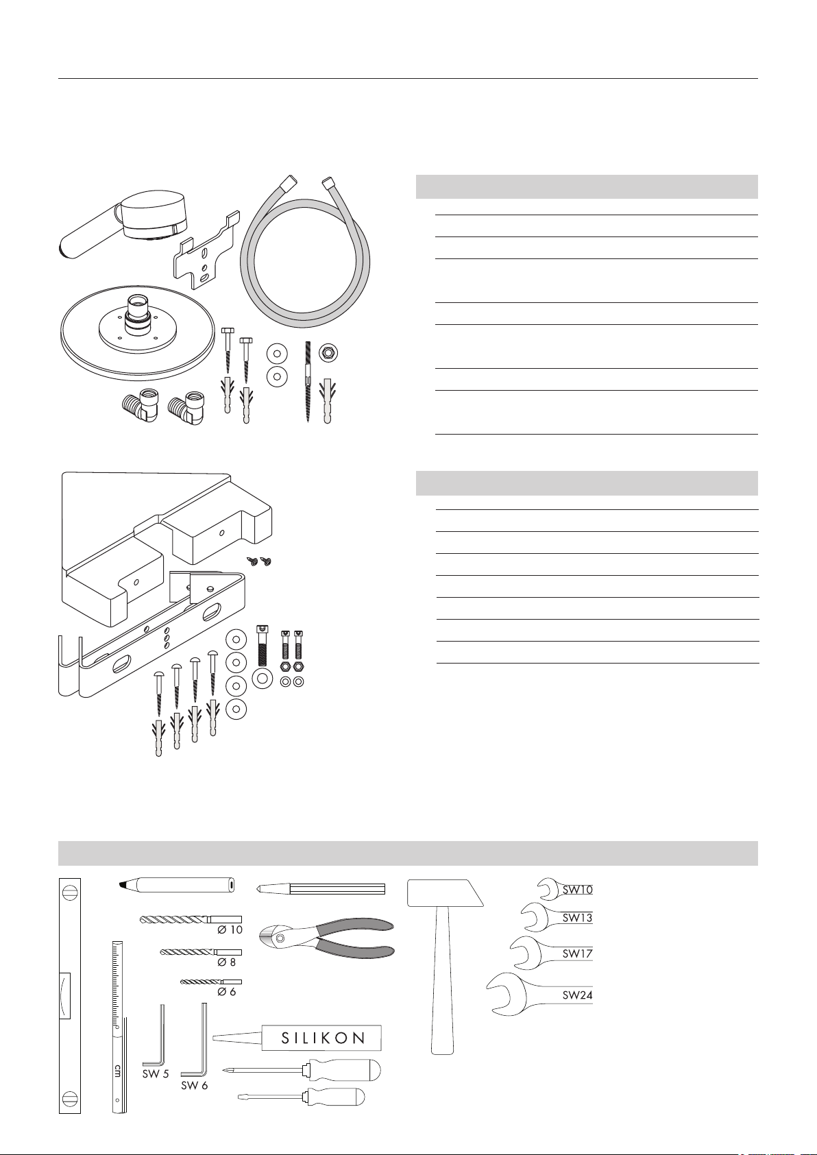
Packing List
g
a
Fitting items Panel
a Handshower
b
c
d
f
e
h
b Isiflex B shower hose 140 cm
c 1 Angle bracket
d 2 Hexagon head cap screws Ø 6 x 50 mm with
plugs SX 8
e 2 Washer A 6,3 x 18
f 1 Set screw M 8 x 80 with 2 nuts M 8 and plug
SX 10
g Overhead shower
h 2 Water connection elbows ½" with filter and non
return valve
Fitting items Corner Installation Set
i
q
k
o
i Cover
k 2 Angle bracket
l 4 Head screws Ø 4,5 x 60 mm with plugs
m 4 Washer A 5,3 x 15
n Socket head cap screw M 8 x 18, washer A 8,4
o 2 Socket head cap screws M 6 x 16, nut M 6
p 2 Washer A 6,4
q 2 EJOT screws KA 50 x 12
l
p
n
m
Tools
free from acetic acid
3
Page 4
4
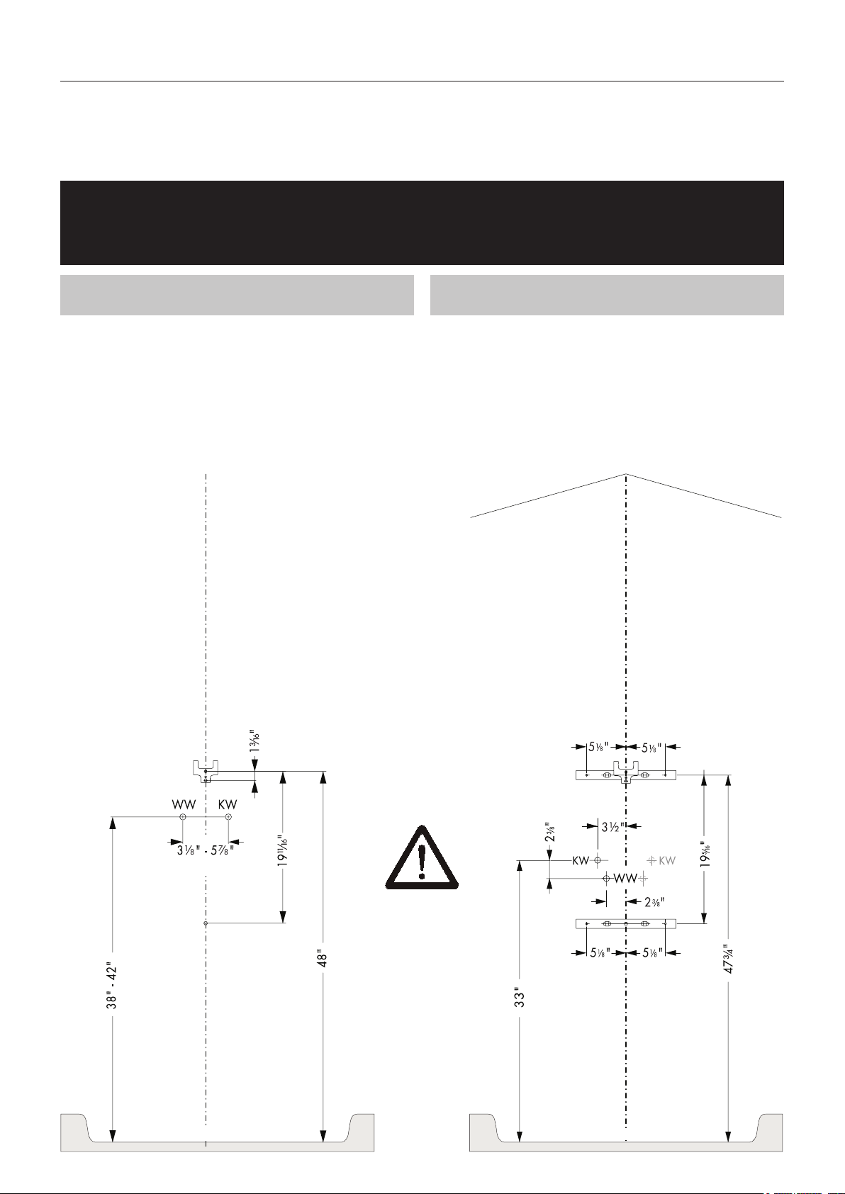
Wall / Corner Installation Dimensions Diagram
Check for required minimum height of 87" from shower tray floor
before starting installation
Wall installation dimensions diagram
KW = cold water
WW = hot water
Corner installation dimensions diagram
Water connections (DN15, ½“)
left wall alternatively.
can be installed on the right or
½" connection
½" connection
Before drilling the lower hole
pay attention if hot and/or cold
water supply pipes cross this
area.
Shower tray floor
Shower tray floor
Page 5
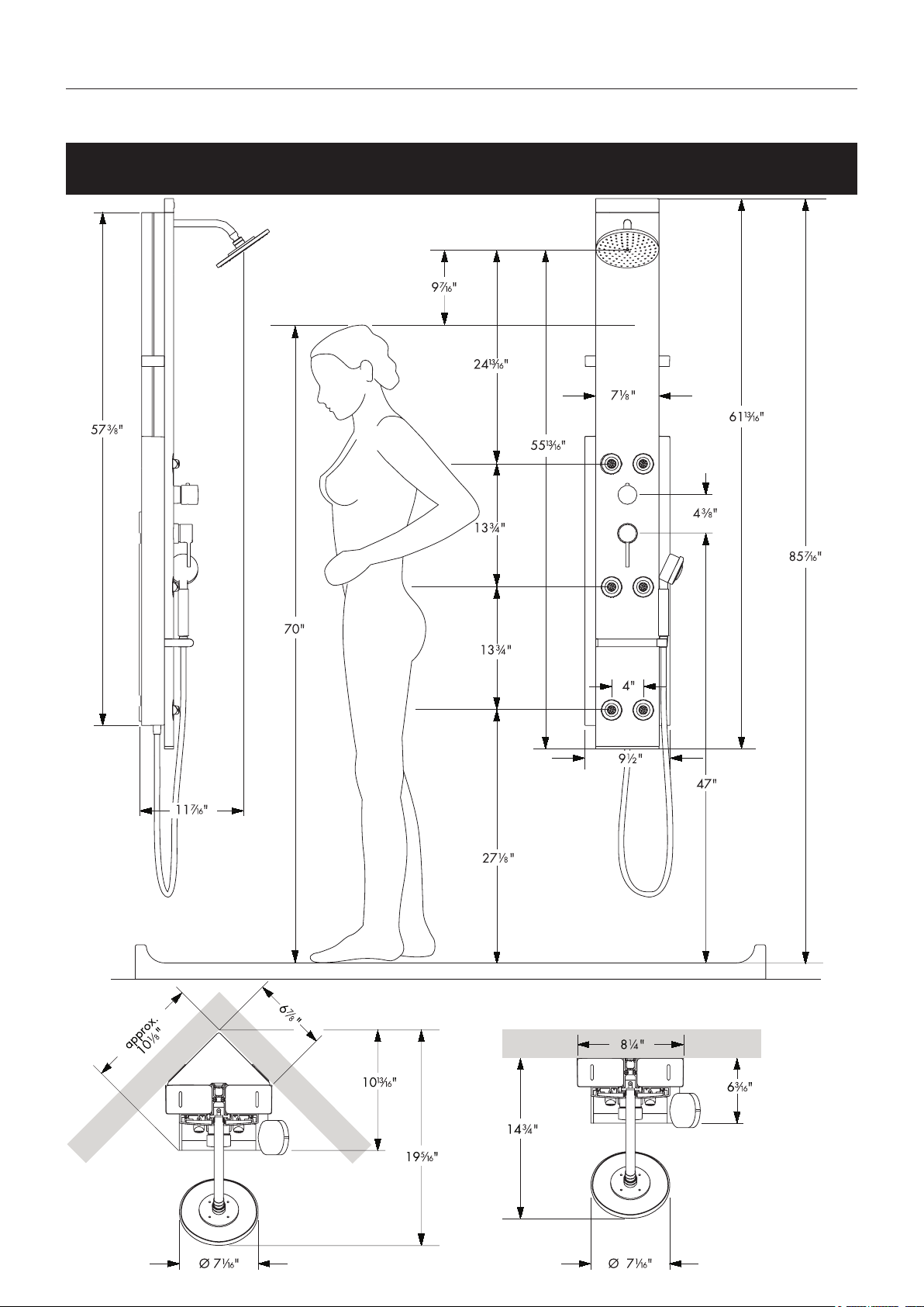
Panel Dimensions
The panel is movable 8" downward. The stated dimensions refer to the
highest position of the panel.
5
Page 6
6
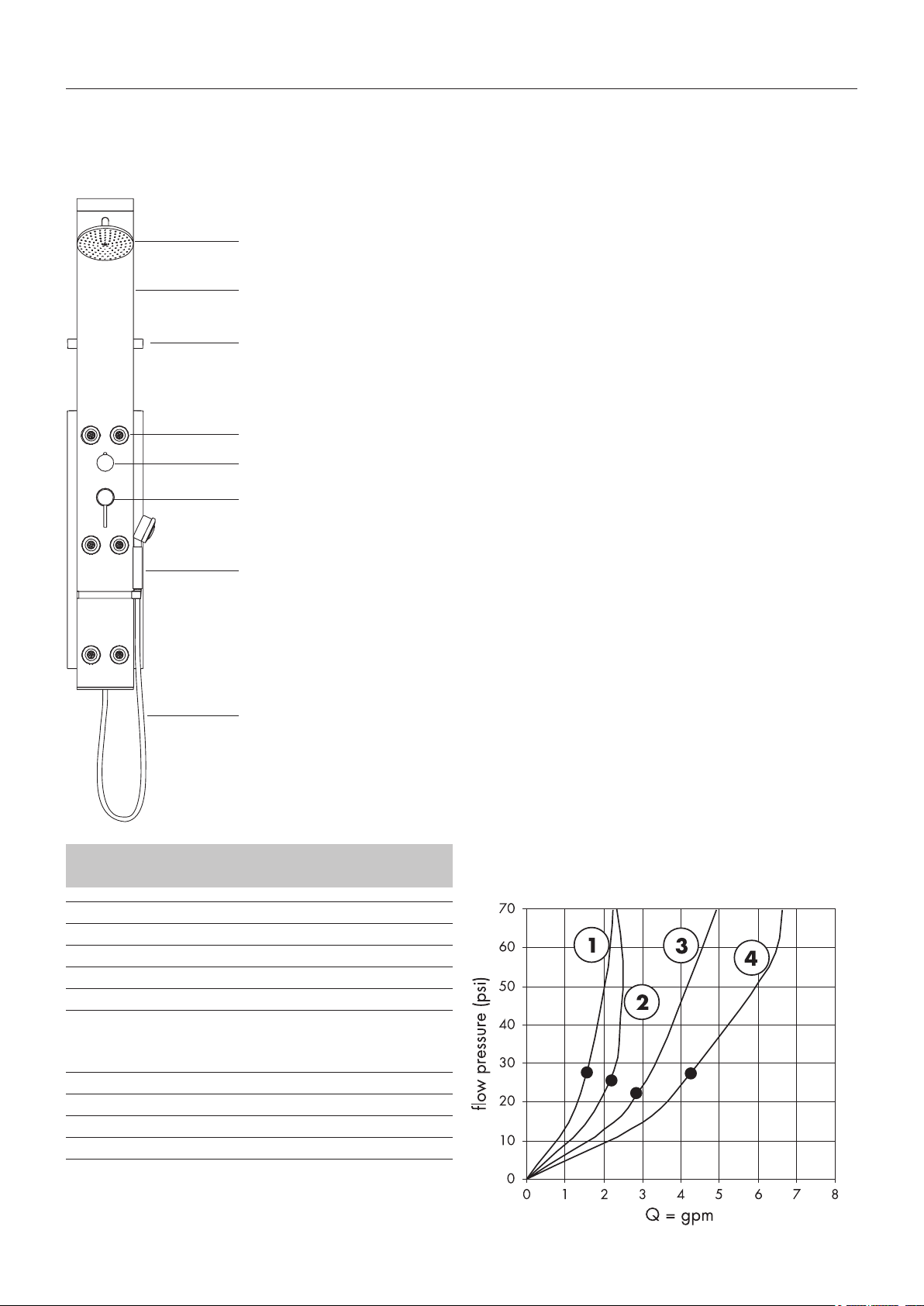
Fittings / Technical Data
Overhead shower
Flow heater:
Applicable for flow heaters at min. 24 kW and 29 psi
flow pressure before the Shower panel. Only one consumer possible, not two simultaneously.
Aluminium profile
Tray
Bodyshower
Thermostat grip
Shut-off/selection valve
Handshower
Shower hose
Pressure differences:
The pressures of the cold and hot water connections must
be balanced.
Maintenance
The non return valves must be checked regularly according with national or regional regulations (at least once a
year!).
Technical Data
Minimum flow pressure 29 psi
Operating pressure max. 147 psi*
Recommended operating pressure 29.4-73.5 psi
Test pressure 235.2 psi
Hot water temperature max. 158 °F
Safety stop 100 °F
Flow capacity at 44 psi
Hand shower (1) 1,9 gpm
Body showers, 6 jets (2) 3,9 gpm
Overhead shower 2,8 gpm
Overhead shower + body showers (3) 5,5 gpm
Hand + body showers 5,0 gpm
* Check applicable codes
The flow rates are limited to 2.5 gpm. These
are the maximum flow rates permitted by the
From • the function is guaranteed.
Page 7

Fitting Items / Water Connections Overview Wall Installation
Fitting items / water connections wall installation
Seal all drill holes with silicone free from acetic acid (not in scope of delivery)
Before drilling the bottom holes pay attention if hot and/or cold
SW10 mm
Ø8 mm
water supply pipes cross this area. In this case, only drill on the
side without any supply pipes.
Dimensions
The installation dimensions stated in this installation instructions are ideal
for people of approximately 70" in body height. The dimensions can be
altered if required. In this case you will have to attend to the minimum height
of 87" from shower tray floor, and alter all the required measurements
as necessary.
If the height of water connection are outside of the illustrated range, the
drill measures have been adjusted accordingly.
(attention for minimum room height of 87 from tub-floor)
SW13 mm
Flush through the supply pipes.
Ø10 mm
7
Page 8

8
Wall Installation
1 2
1.
SW
24 mm
1.
2.
2.
Page 9

3 4
Wall Installation
SW
2 mm
SW 13 mm
Adjustment Thermostatic mixer please see page 14
9
Page 10

10
Fitting Items / Water Connections Overview Corner Installation
Fitting items / water connections corner installation
Seal all drill holes with silicone free from acetic acid (not in scope of delivery)
2x
SW
5 mm
SW10 mm
2x
Ø6 mm
Before drilling the bottom holes pay attention if hot and/or cold
water supply pipes cross this area. In this case, only drill on the
side without any supply pipes.
Dimensions
The installation dimensions stated in this installation instructions are ideal
for people of approximately 70" in body height. The dimensions can be
altered if required. In this case you will have to attend to the minimum height
of 87" from shower tray floor, and alter all the required measurements
as necessary.
If the height of water connection are outside of the illustrated range, the
drill measures have been adjusted accordingly.
(attention for minimum room height of 87 from tub-floor)
Flush through the supply pipes.
SW
6 mm
1x
2x
Ø6 mm
Page 11

1
Corner Installation
2
3
11
Page 12

12
Corner Installation
4 5
1.
2.
SW
24 mm
1.
2.
Page 13

6 7
Corner Installation
SW
17 mm
SW 13 mm
Adjustment Thermostatic mixer please see page 14
13
Page 14

14
Thermostat Setting / Safety Function
Safety Function (1-5)
The desired maximum temperature for example max. 108 °F can be pre-set thanks to the safety function
1 2 3
4 5
Thermostat Setting (6-7)
- Set Quattrostat to "Hand shower".
- Open Quattrostat, adjust thermostat to 100 °F.
- Push thermostat grip on and align vertically (red button
6 7
A points upwards), screw tight
A
Page 15

8"
(150 N)
Trouble Shooting
English
Fault Cause Remedy
water level is too low filter in angled hose connection is dirt clean filter
handshower delivering insufficient water filter of handshower dirty clean filter
temperature regulation not possible (only hot thermostatic cartridge defective exchange thermostatic cartridge
or cold water) at new installation: connection hose exchanged install connection hose correct
shower is dripping cartridge of Quattrostat defective exchange cartridge
cartridge of Quattrostat stiff nut of cartridge screwed to tight first screw nut of cartridge tight, than loosen
the nut approx. 12°
15
Page 16

16
Exchanging lateral shower head
1
Page 17

10
Spare Parts
1
29 x 2,5
25 x 2
23 x 2
8
7
14
11
15
13
9
3
16
4
2
12
17
18
6
5
Pos. Description Nr./No./Nr. VE
1 head shower 97195XX1 1
shower arm 97196XXX 1
2 handshower 98552XX1 1
3 handle for thermostat 38391XX1 1
sleeve 95032XXX 1
4 handle 10490XXX 1
flange 97057XXX 1
5 hose 25941XXX 1
6 body shower 97197001 1
escutcheon 97198XXX 1
spray head 28408XXX 1
7 cartridge on/off control 96645000 1
8 thermostat cartridge 94282000 1
sealing set 95037000 1
9 shelf 97199000 1
10 upper cover 97200XXX 1
11 lower cover 97201XXX 1
12 connetion hose 900 mm 97202000 1
13 mounting kit 97203001 1
14 handle with showerholder 98579XXX 1
15 gas spring 98611000 1
16 elbow NPT ½" 97582000 1
17 sliding roller 98890000 1
18 corner fitting set 2621X000 1
XXX = Colors
000 chrome plated
810 satinox
880 satin chrome
17
Page 18

18
Cleaning Instruction
English
Cleaning Recommendation for Hansgrohe Products
Modern sanitary tapware, kitchen mixers and showers consist of very different materials to comply with the needs of the market with
regard to design and functionality.
To avoid damage and reclamations, it is necessary to consider certain criteria when cleaning.
Cleaning Materials for Mixers and Showers
Acids are necessary ingredients of cleaning materials for removing lime, however please pay attention to the following points when cleaning mixers and showers:
• Only use cleaning material which is explicitly provided for this type of application, such as Hansgrohe’s Decalcifying Agent (A), which
is available through the specialist sanitary trade.
• Never use cleaning materials, which contain hydrochloric, formic or acetic acid, as they cause considerable damage.
• Phosphoric acid is also restricted as it can cause damage.
• Never mix any cleaning material with another.
• Never use cleaning materials or appliances with an abrasive effect, such as unsuitable cleaning powders, sponge pads or micro fibre
cloths.
Cleaning Instructions for Mixers and Showers
Please follow the cleaning material manufacturer’s instructions. In addition pay attention to the following points:
• Clean the mixers and showers as and when required
• The cleaning dosage and time the cleaner needs to take effect should be adjusted according to the product and the cleaner should not
be left longer than necessary.
• Regular cleaning can prevent calcification.
• When using spray cleaner, spray first into a cloth or sponge never directly onto the sanitary tapware, as drops could enter openings
and gaps and cause damage.
• After cleaning rinse thoroughly with clean water to remove any cleaner residue.
Important
Residues of liquid soaps, shampoos and shower foams can also cause damage, so rinse with clean water after using.
If the surface is already damaged, the effect of cleaning materials will cause further damage.
Damage caused by improper treatment will not be covered by our guarantee.
A
Rubit
Cleaning the hand and
head shower
With the manual cleaning
function “Rubit”, jet former calcinations can
be removed by simple
rubbing.
Quiclean
Cleaning the hand-shower
Handshower with “Quiclean”, the cleaning function
against calcinations. When
the jet types are changed,
small cleaning pins remove
the calcinations.
Page 19

Warranty
Limited Lifetime Consumer Warranty
This product has been manufactured and tested to the highest quality standards by Hansgrohe, Inc. („Hansgrohe“). This warranty is limited to Hansgrohe products
which are purchased by a consumer in the United States after March 1, 1996, and installed in either the United States or Canada.
WHO IS COVERED BY THE WARRANTY
This warranty extends to the original consumer purchaser only.
WHAT IS COVERED BY THE WARRANTY
This warranty covers only your Hansgrohe manufactured product. Hansgrohe warrants this product against defects in material or workmanship as follows: Hansgrohe
will repair at no charge for parts only or, at its option, replace any product or part of the product which proves defective because of improper workmanship and/or material, under normal installation, use, service and maintenance. If Hansgrohe is unable to provide a replacement and repair is not practical or cannot be timely made,
Hansgrohe may elect to refund the purchase price in exchange for the return of the product.
LENGTH OF WARRANTY
Replacement or repaired parts of products will be covered for the term of this warranty as stated in the following two sentences. If you are a consumer who purchased
the product for use primarily for personal, family, or household purposes, this warranty extends for as long as you own the product and the home in which the product
is installed. If you purchased the product for use primarily for any other purpose, including, without limitation, a commercial purpose, this warranty extends only (i) for
1 year, with respect to Interaktiv and Retroaktiv products, and (ii) for 5 years, with respect to AXOR, ShowerPower and Pharo products.
THIS WARRANTY DOES NOT COVER, AND HANSGROHE WILL NOT PAY FOR:
A. Conditions, malfunctions or damage not resulting from defects in material or workmanship.
B. Conditions, malfunctions or damage resulting from (1) improper installation, improper maintenance, misuse, abuse, negligence, accident or alteration, or (2) the
use of abrasive or caustic cleaning agents or “no rinse” cleaning products, or the use of the product in any manner contrary to the product instructions.
C. Labor or other expenses for the disconnection or return of the product for warranty service, or for installation or reinstallation of the product.
D. Accessories or related products not manufactured by Hansgrohe.
TO OBTAIN WARRANTY SERVICE
Contact your Hansgrohe retailer, or write to Technical Service at:
Hansgrohe Inc.
1492 Bluegrass Lakes Parkway
Alpharetta GA 30004
Or, call Hansgrohe toll-free at (800) 334-0455.
In requesting warranty service, you will need to provide
1. The sales receipt or other evidence of the date and place of purchase.
2. A description of the problem.
3. Delivery of the product or the defective part, postage prepaid and carefully packed and insured, to Hansgrohe Inc. 1492 Bluegrass Lakes Parkway, Alpharetta,
Georgia 30004, Attention: Technical Service, if required by Hansgrohe.
When warranty service is completed, any repaired or replacement product or part will be returned to you postage prepaid.
EXCLUSIONS AND LIMITATIONS
REPAIR OR REPLACEMENT (OR, IN LIMITED CIRCUMSTANCES, REFUND OF THE PURCHASE PRICE) AS PROVIDED UNDER THIS WARRANTY IS THE
EXCLUSIVE REMEDY OF THE PURCHASER. HANSGROHE NEITHER ASSUMES NOR AUTHORIZES ANY PERSON TO CREATE FOR IT ANY OBLIGATION OR LIABILITY IN CONNECTION WITH THIS PRODUCT.
HANSGROHE SHALL NOT BE LIABLE TO PURCHASER OR ANY PERSON FOR ANY INCIDENTAL, SPECIAL, OR CONSEQUENTIAL DAMAGES, ARISING OUT OF BREACH OF THIS WARRANTY OR ANY IMPLIED WARRANTY (INCLUDING MERCHANTABILITY).
Some States do not allow the exclusion or limitation of incidental or consequential damages, so the above limitation or exclusion may not apply to you.
This warranty gives you specific legal rights, and you may have other rights which vary from State to State.
You may be required by law to give us a reasonable opportunity to correct or cure any failure to comply before you can bring any action in court against us under the
Magnuson-Moss Warranty Act.
PRODUCT INSTRUCTIONS AND QUESTIONS
Upon purchase or prior to installation, please carefully inspect your Hansgrohe product for any damage or visible defect. Prior to installing, always carefully study the
enclosed instructions on the proper installation and the care and maintenance of the product. If you have questions at any time about the use, installation, or performance of your Hansgrohe product, or this warranty, please call or write to us at the toll-free number and address printed above.
19
Page 20

20
Hansgrohe · Postfach 1145 · D-77761 Schiltach · Telefon +49 (0) 78 36/51-1282 · Telefax +49 (0) 7836/511440
E-Mail: info@hansgrohe.com · Internet: www.hansgrohe.com
03/2009
9.05185.03
 Loading...