

Hansgrohe Interaktiv Showerpanel Installation Instructions / Warranty
Interaktiv
Showerpanel
Installation Instructions / Warranty

Interaktiv Showerpanel I
Interaktiv Showerpanel II
Showerpanel I Showerpanel II
handshower & bodyjets handshower, bodyjets, tub spout
Metro 06572000 06573000
Solaris 06549XX0 06550XX0
Stratos 06564XX0 06565XX0
Interaktiv S 06893000 06894000
Proaktiv* 06964000 06971000
Product Specification
Flow rate of handshower 2.5 gpm
Flow rate of each bodyjet 1.0 gpm
Maximum flow rate of thermostatic mixing valve 8 gpm @ 45 psi
10 gpm @ 65 psi
Recommended incoming hot water temperature 120
o
– 140o F**
Recommended incoming water pressure 45 – 72 psi
Anodized aluminum body
Listed by Underwriters Laboratories
Backflow protection provided by check valve in handshower outlet.
The high temperature limit stop on the thermostatic mixing valve cartridge can be re-set to
comply with local plumbing codes -- see page 13.
*Proaktiv showerpanels are sold without trim. Proaktiv showerpanel trim kits are sold separately.
**Please know and follow all applicable local plumbing codes when setting the temperature on the water heater. In
Massachusetts, the water heater may be set no higher than 112oF.
2
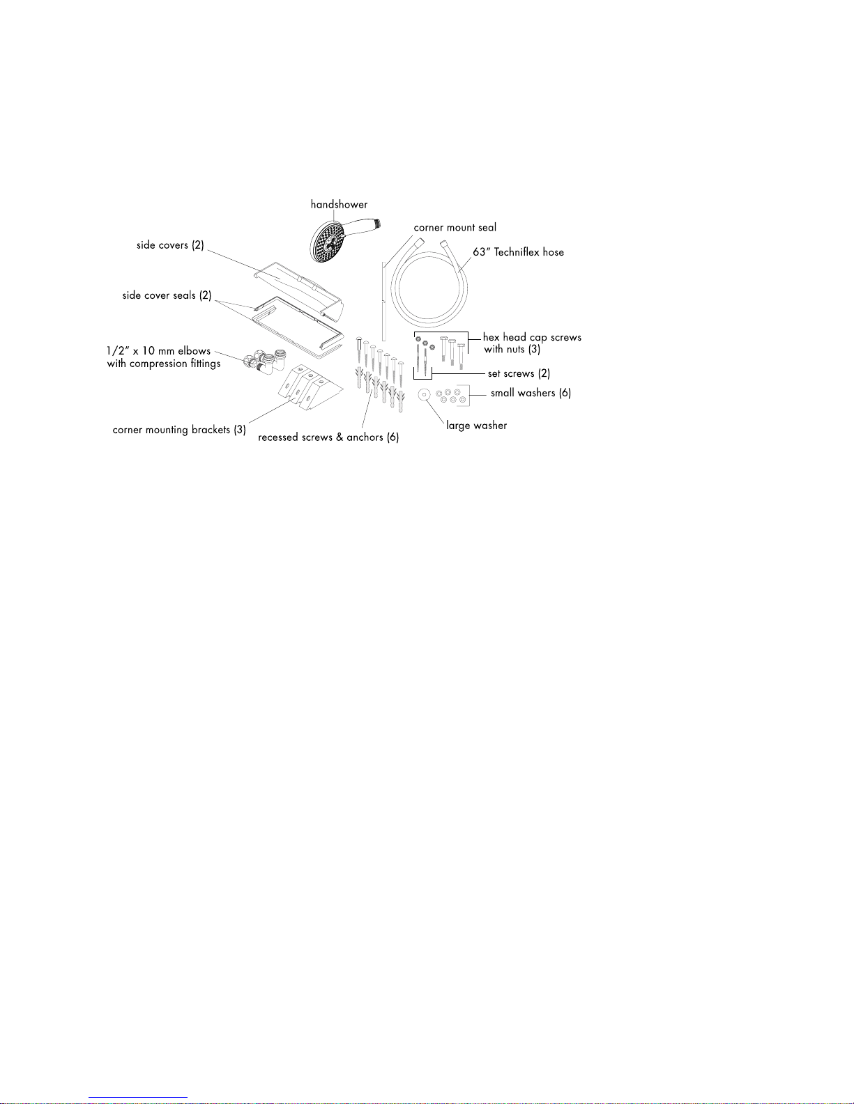
Check Package Contents
Save time and aggravation. Before beginning installation, check the contents of this
package. Make sure that all parts are present and in good condition. If any part is missing
or damaged, please contact Hansgrohe Customer Service before proceeding.
Tools Required
The following tools are suggested for installing the Interaktiv Showerpanel:
Tape measure
Level
Grease pencil or other marking device
Drill with 6 mm bit suitable for wall surface
10 mm nut driver
10, 11 and 19 mm wrenches
3 mm Allen wrench
Philips screwdriver
Waterproof sealant
Mallet (to install anchors)
Teflon
thread tape
Note: the handshower
and Techniflex hose are
not included with the
Proaktiv showerpanel.
They are included with
the trim kit (sold separately).
3
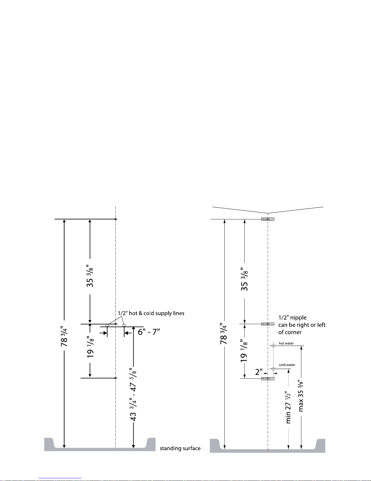
Roughing-in
This unit can be installed on a flat wall or in a 90o corner. Instructions for installation on a
flat wall begin on page 5. Go to page 8 if the panel is to be installed in a corner.
Ensure that you have a minimum 83” ceiling height from the standing
surface.
Stub out 1/2" NPT male nipples for the hot and cold water supplies at the locations shown
on the appropriate rough-in diagram. The nipples should extend 5/8" outside the surface
of the finished wall.
Install the wall surface and make the wall watertight before installing the panel
. The panel
hangs on the finished wall. Seal the wall around the nipples with waterproof sealant.
4
Installation on a Flat Wall Installation in 90o Corner
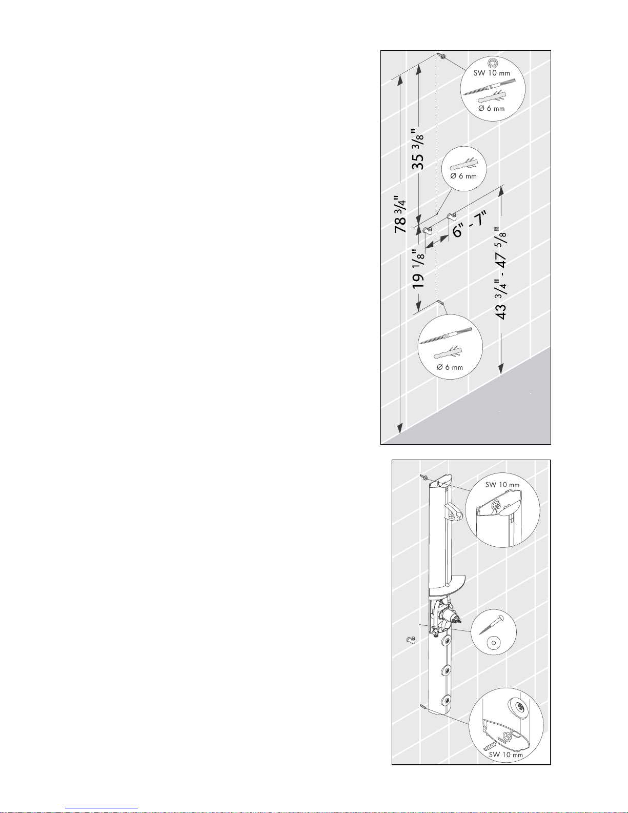
Installation -- Flat Wall
Wrap the threads on the supply nipples with Teflon thread
tape.
Install the enclosed elbows so that the outlets face
upwards.
Measure up the wall 78 ¾”, making sure that the line is
plumb. Mark the position for the top screw hole.
From the position of the top screw hole, measure down
35 3/8”. Mark the position for the center screw hole.
From the center screw hole, measure down 19 1/8”.
Mark the position for the bottom screw hole.
Use a 6 mm drill bit suitable for the wall surface. Drill the
three screw holes.
Install the anchors. Seal the wall around the anchors with
waterproof sealant.
Install the set screws in the top and bottom holes.
Use a 10 mm nut driver to attach a nut to the top set
screw.
Slide the panel over the top and bottom set screws.
Tighten the nut on the top set screw.
Install and tighten the nut on the bottom set screw.
Install one recessed head screw and the large washer on
the center hole. Tighten the screw.
5
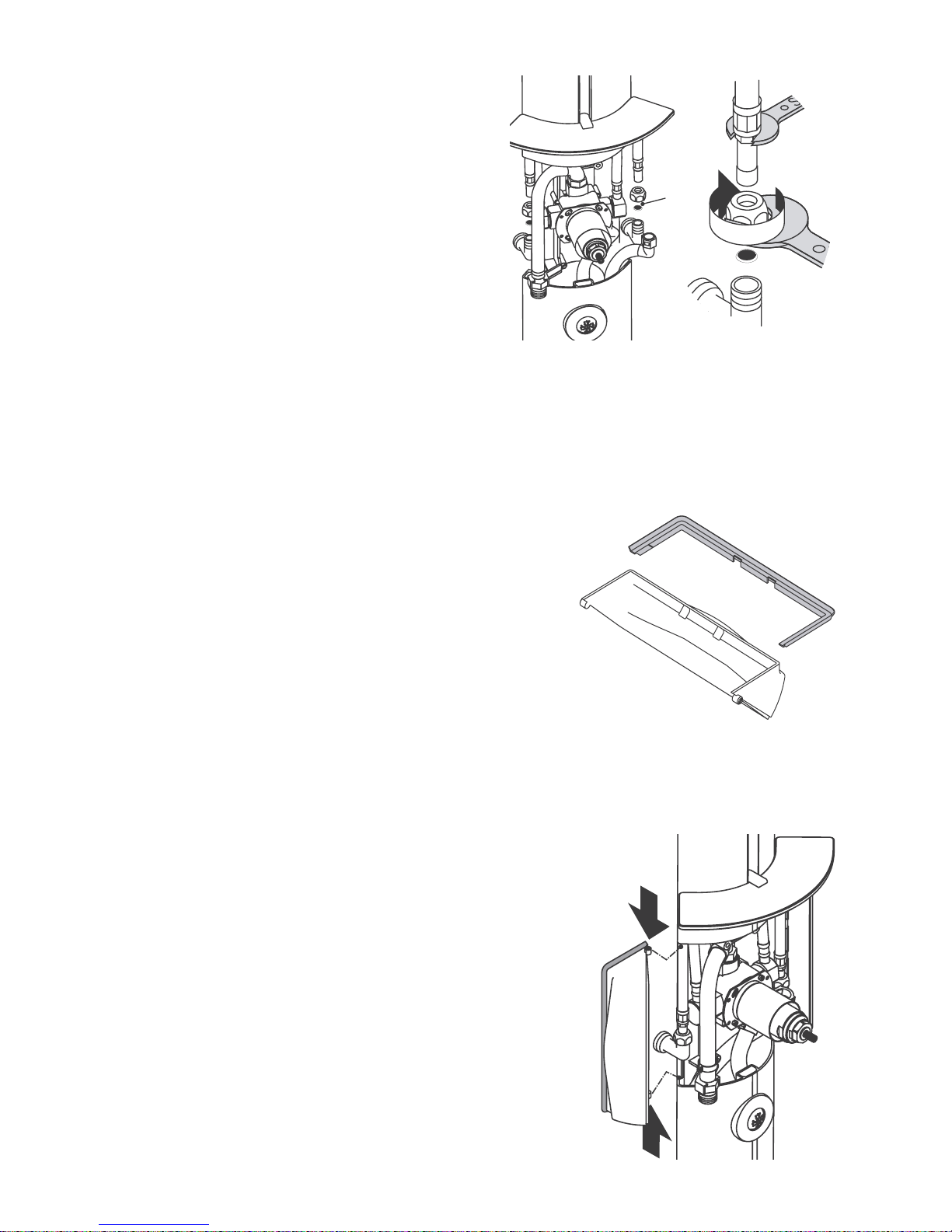
Use the compression nuts and ferrules to connect
the supply hoses on the panel to the supply
elbows. Use two wrenches, as shown, to prevent
the supply hoses from twisting.
Attach the seals to the side covers.
Install the side covers. The pins on the covers must go into
the grooves on the sides of the panel.
6
 Loading...