

Page 1
Installation Instructions / Warranty
ShowerArc
26396001
Page 2
ShowerArc
26396001
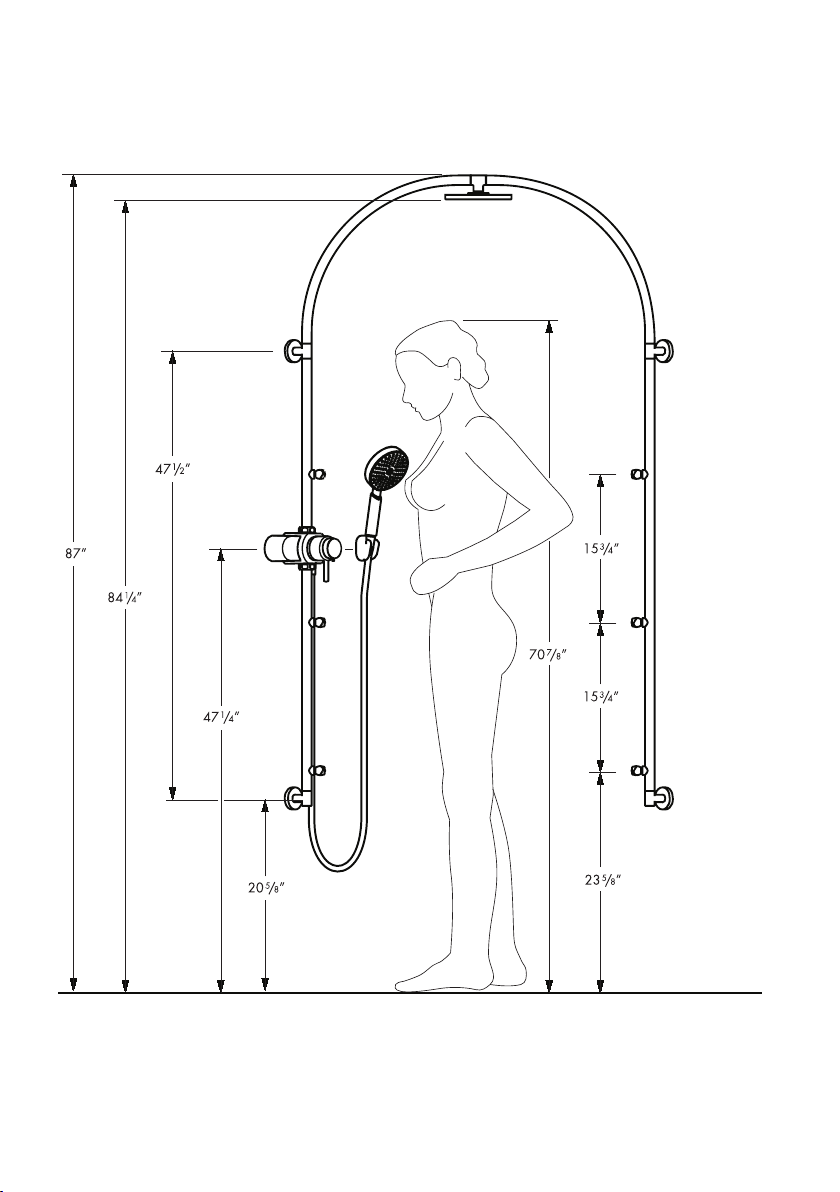
Minimum ceiling height – 90 1/2”
2
Page 3

Installation Considerations
For best results, Hansgrohe recommends
•
that this unit be installed by a licensed,
professional plumber.
Please read over these instructions thor-
•
oughly before beginning installation.
Make sure that you have all tools and supplies needed to complete the installation.
Inspect the ShowerArc thoroughly for ship-
•
ping damage before beginning installation.
The installation shown on page 2 is ideal
•
for users of approx. 5’11” in height The
installation height may be increased, if
desired. All measurements, including the
minimum ceiling height, must be increased
as well.
The ShowerArc requires 1/2” NPT female
•
fittings, one for the hot supply and one for
the cold supply, recessed 3/8”
behind the surface of the
finished wall.
The thermostatic mixing valve may be
•
installed on either side of the shower. For
proper operation of the thermostatic mixing
valve, the hot supply must enter the valve
on the left and the cold supply must enter
the valve on the right. If the valve is crossconnected, it cannot function correctly.
The difference in water pressure between
•
the hot and cold supplies should not
exceed 10 psi or the thermostatic mixing
valve cannot work properly.
The hot and cold supplies must be thor-
•
oughly flushed before installation of the
ShowerArc.
The finished wall surface (tile,
•
etc) must be installed before
the ShowerArc can be installed.
Use caution when drilling the mounting
•
holes. Be careful not to drill into water
lines!
Protection against backflow is provided by
•
check valves. The check valves should be
removed and cleaned yearly -- please see
the maintenance note on page 29.
The ShowerArc is not for use with an
•
instantaneous water heater.
Technical Information
Recommended water pressure 43.5 - 72.5 psi
Minimum water pressure 43.5 psi
Max. water pressure 145 psi
Recommended hot water temp. 120� - 140� F*
Max. hot water temp 165�F*
Flow rate - showerhead 2.5 gpm
bodysprays 0.6 gpm each
handshower 2.5 gpm
The thermostatic mixing valve has a high temperature limit stop which may be reset to comply with
local plumbing codes -- see page 23.
This unit is listed by IAPMO.
*Please know and follow all applicable local plumbing codes when setting the temperature on the water heater. In
Massachusetts, the water heater may be set no higher than 112�F.
3
Page 4
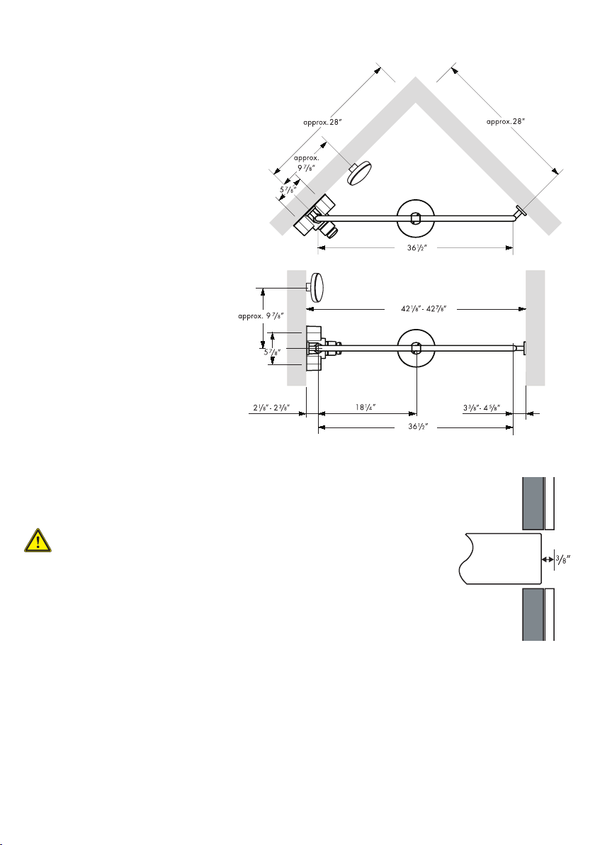
Installation in 90º corner:
Instructions begin on page 5
Wall-to-wall installation
Requires 26397000 installation kit
(included): Instructions begin on
page 13.
Roughing-in
The ShowerArc requires 1/2” NPT female fittings, recessed 3/8” behind
the surface of the finished wall, for the hot and cold water supplies for
the thermostatic mixing valve.
4
Page 5
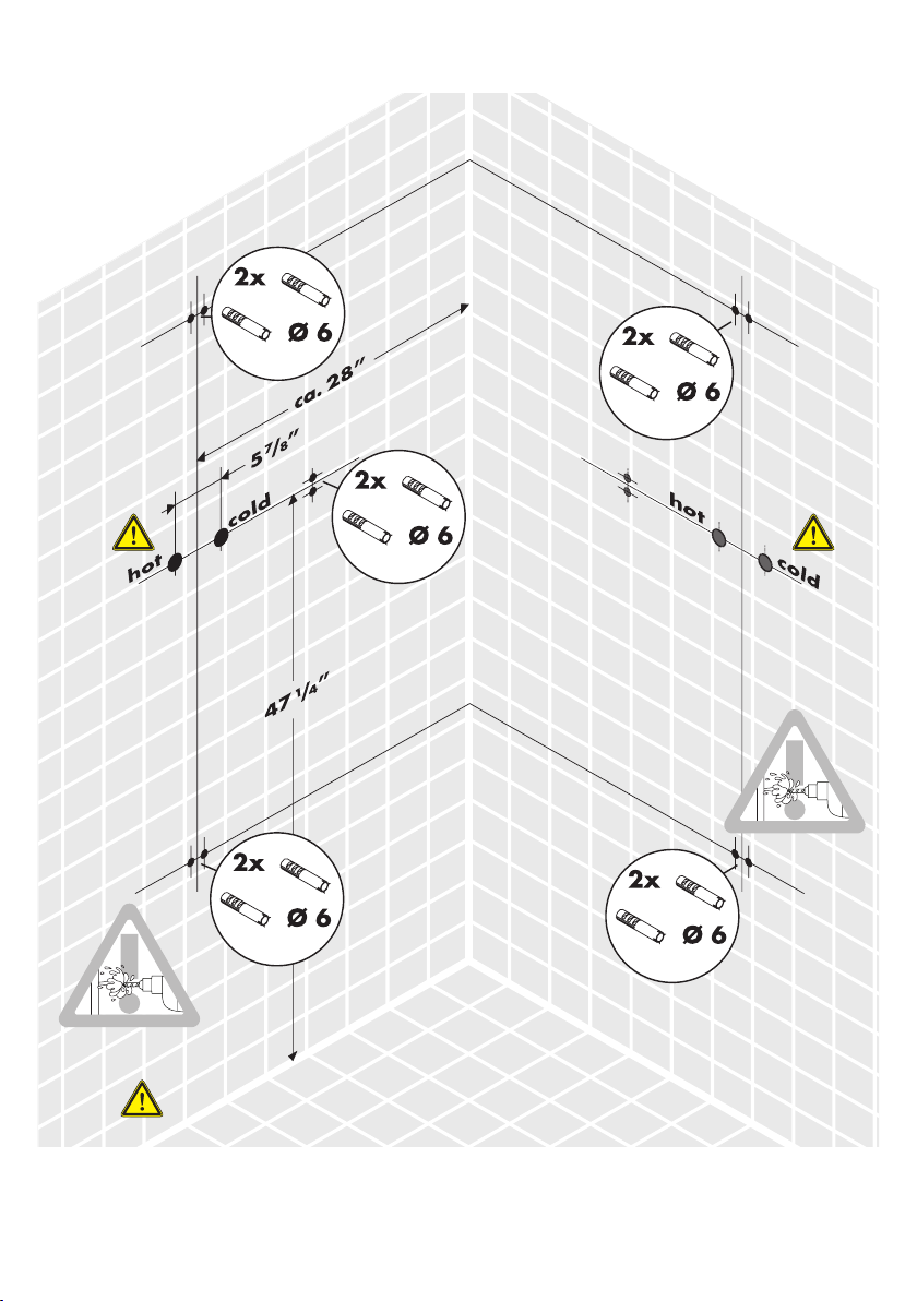
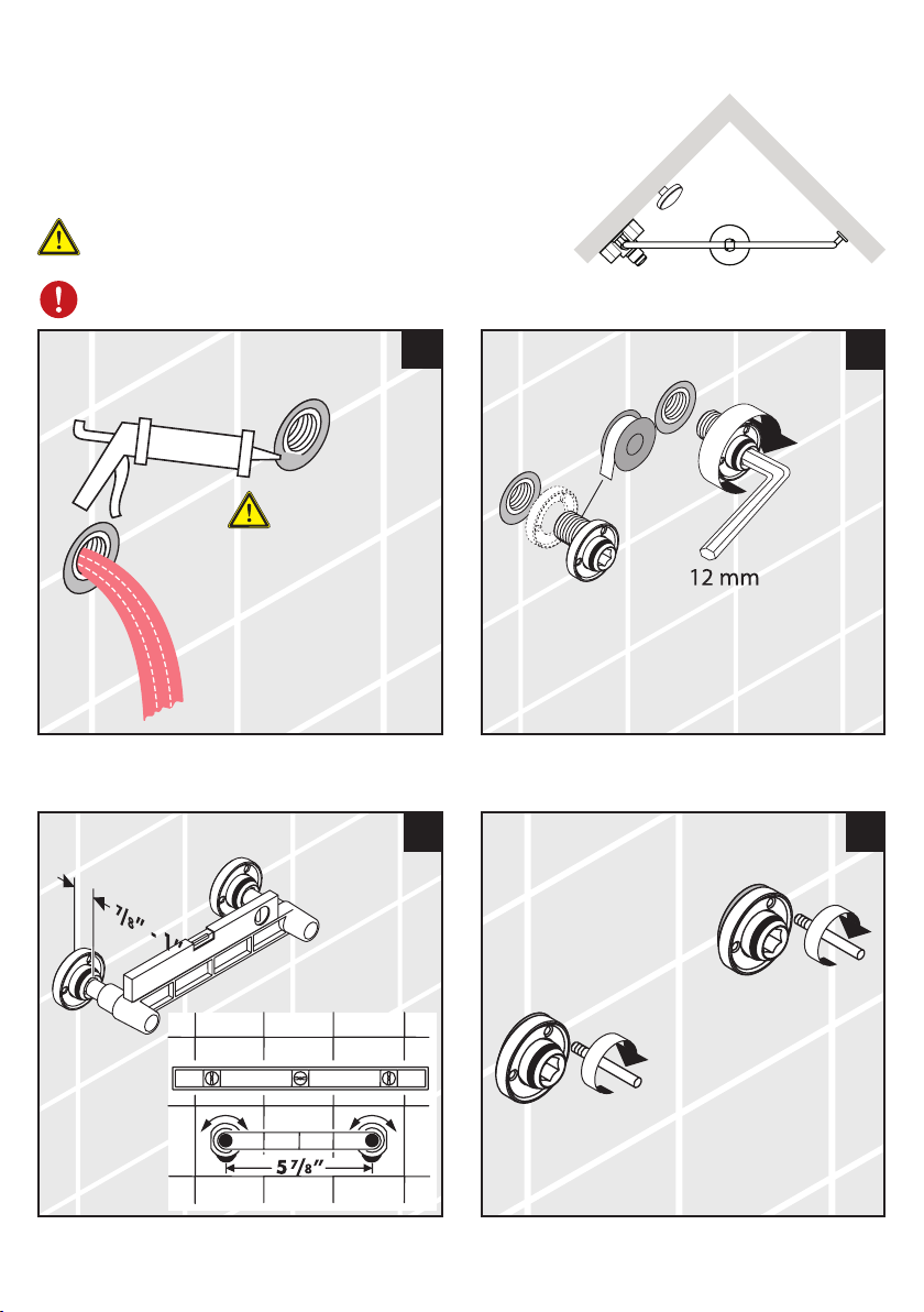
Installation in 90º corner
Only one set of supplies is required – do not install two
sets of supplies.
The thermostatic mixing valve may be installed on either wall. This diagram shows both possible
positions for the installation.
5
Page 6
Installation in 90º Corner
Seal the wall around the supplies
with waterproof sealant.
Failure to seal the wall can lead to
possible water damage.
1
2
3 4
6
Page 7
5
6
7
8
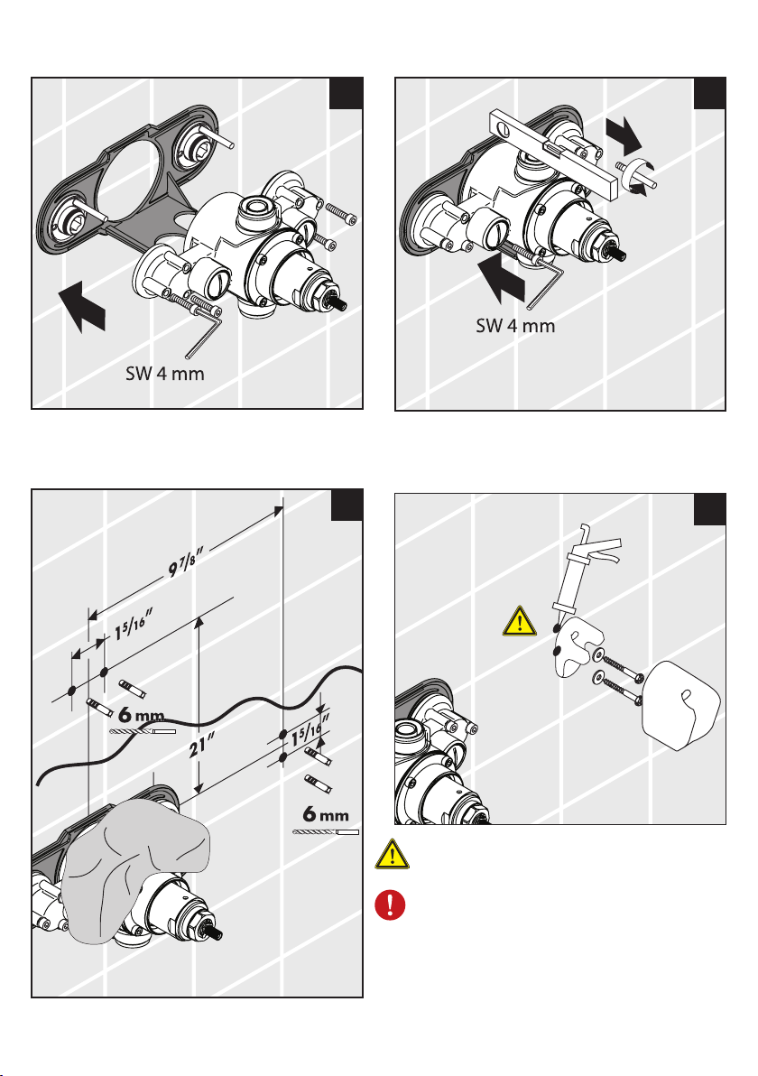
Seal the wall around the
anchors with waterproof
sealant.
Failure to seal the wall can lead
to possible water damage.
7
Page 8
11
9
10
Seal the wall around the anchors
with waterproof sealant.
Failure to seal the wall can lead
to possible water damage.
Be careful not to drill into water
lines!
12
6 mm
8
Page 9
13 14
15 16
9
Page 10
17 18
10
19
20
1
2
6 mm
Page 11

21 22
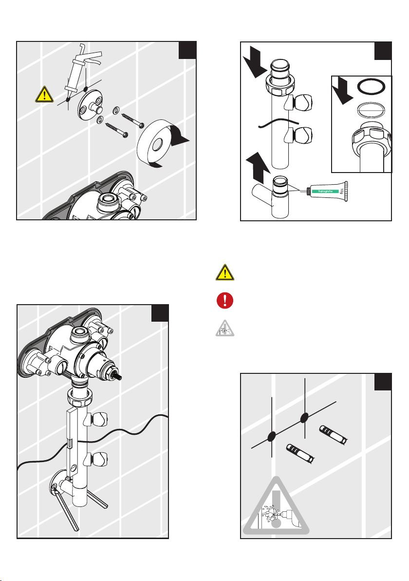
Seal the wall around the
anchors with waterproof
sealant.
Failure to seal the wall
can lead to possible water
damage.
23
24
2
1
6 mm
11
Page 12

25
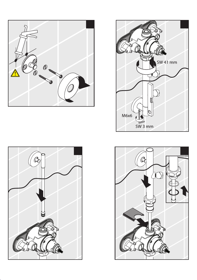
Seal the wall around the anchors
with waterproof sealant.
Failure to seal the wall can lead
to possible water damage.
26
Turn to page 22 to continue the installation.
12
Page 13

Wall-to-Wall Installation
Only one set of supplies is required – do not install two
sets of supplies.
The thermostatic mixing valve may be installed on either wall. The diagram shows both possible
positions for the installation.
13
Page 14

Wall-to-Wall Installation
Seal the wall around the supplies
with waterproof sealant.
Failure to seal the wall can lead to
possible water damage.
1
3 4
2
14
Page 15

5 6
7
8
Seal the wall around the anchors
with waterproof sealant.
Failure to seal the wall can lead
to possible water damage.
15
Page 16

9
10
16
11
2
Seal the wall around the
6 mm
1
anchors with waterproof
sealant.
Failure to seal the wall can lead
to possible water damage.
Be careful not to drill into water
lines!
12
Page 17

13 14
Install the 26397000 mounting set
15
16
17
Page 18

XX
90
XX =
17 18
18
19
20
Page 19

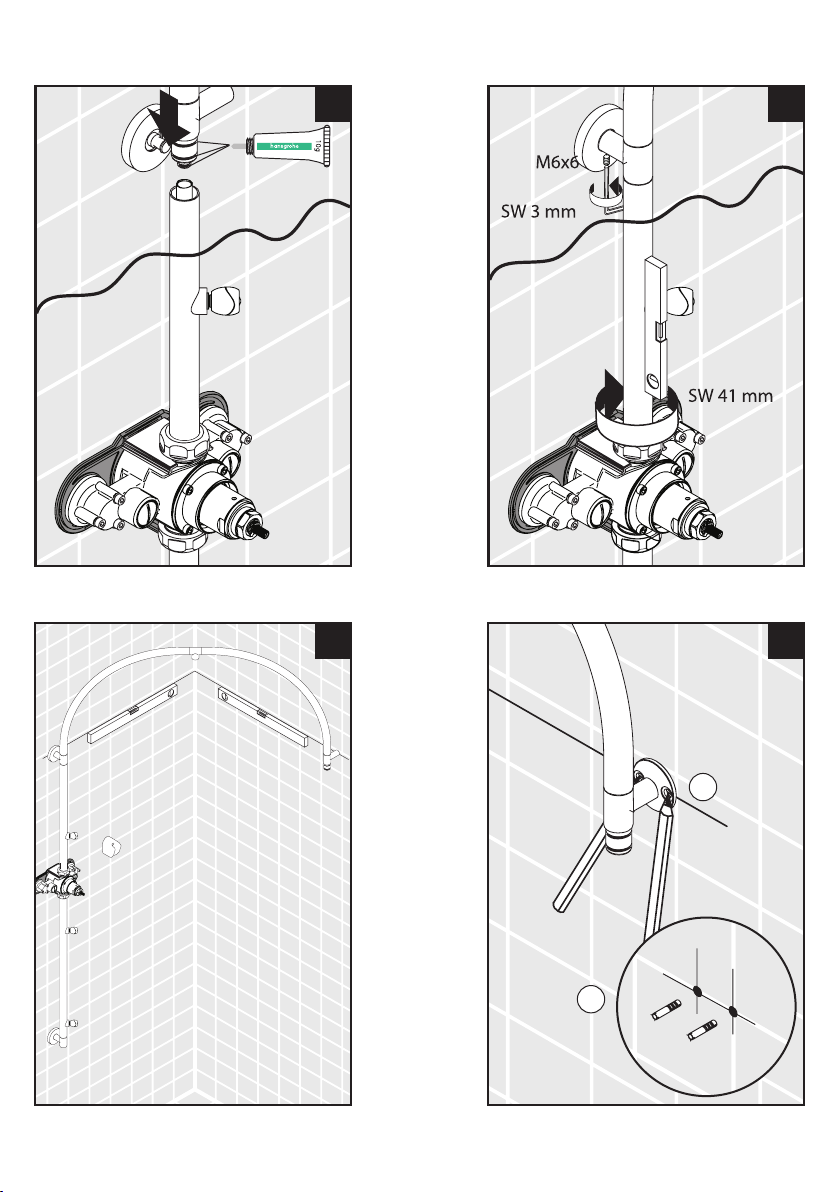
SW 3 mm
M6x8
21 22
1
2
6 mm
23
24
19
Page 20

Install the 26397000 mounting set
M6x60
1.
2.
3.
SW 3 mm
M6x8
25 26
20
2
6 mm
27
1
Seal the wall around the anchors with waterproof sealant.
Failure to seal the wall can lead
to possible water damage.
28
Page 21

SW 3 mm
M6x8
29
Turn to page 22 to continue the installation.
21
Page 22

Install the Cover, Escutcheon, and Handle
Install the Showerhead and Handshower
21
22
Page 23

Reset the High Temperature Limit Stop
KLICK
Loosen the handle screw with a 3 mm Allen wrench.
Remove the retainer clip and stop ring from the stem.
Turn the stop unit to the handshower position.
1
2
3
Turn the temperature control stem until the output
water is the desired high temperature -- usually
110º.
4
23
Page 24

Turn the stop unit to the off position.
KLICK
SW 3 mm
5
Install the stop ring so that the tooth is against the stop. Install
the clip.
Install the handle. Tighten the handle screw with a 3 mm Allen
wrench.
6
7
24
Page 25

Justify the Handle
Turn the diverter handle to the handshower
position.
Turn the temperature control knob until the
output water is 100ºF.
Turn the diverter handle to the off position.
Loosen the handle screw with a 3 mm Allen
wrench.
Remove the handle.
Align the indexing mark on the temperature
control knob with the 100º mark.
1
2
3
Replace the handle. Tighten the handle screw.
4
25
Page 26

User Instructions
Turn the temperature control knob to change the temperature. Turn it clockwise to make the water cooler,
counter-clockwise to make the water warmer.
When the knob is turned counter-clockwise to the 100º
position it will stop. To obtain water hotter than 100º,
push the knob in, and continue turning it counter-clockwise.
Turn the diverter handle to select the handshower,
bodysprays, or showerhead. If the indicator on
the handle is positioned between the showerhead
and bodyspray positions, water will come from
both.
Using the Handshower
26
Turn the function lever to until the desired spray mode has
been obtained.
function
lever
Page 27

Cleaning the Handshower
The handshower uses the Rubit™ cleaning system. If
scale deposits are noticed in the spray channels, rub
across the channels with a finger or a sponge to dislodge
them.
If necessary, pour about 3/4” of a commercial scale
remover, such as Lime-Away or CLR, into a shallow dish.
Soak the spray face for the amount of time shown in the
label instructions.
Rinse the spray face with clear water.
Reinstall the handshower. Flush the handshower for at
least one minute before using.
27
Page 28

Replacement Parts
19
9
15
16
1
2
20
23
7
17
18
21
14
24
5
6
11
13
17
10
3
25
26
8
22
12
28
4
25
Page 29

1 wall flange 96768000
2 escutcheon 96767000
3 branch connection 97496000
4 branch connection 97497000
5 shower hose 28276000
6 handshower 28504001
7 handshower holder 28321000
8 body spray 97603000
9 showerhead 97195001
10 handle 25971000
11 shutoff unit with selector 97976000
12 escutcheon 97491000
13 thermostat cartridge 94282000
14 noise reducer 94073000
15 ball s-union 96742001
16 rear panel 97493000
17 cover 97494000
18 sleeve nut 97492000
19 pipe elbow 97495000
20 pipe 97499000
21 pipe 97500000
22 pipe 97501000
23 inner standpipe 97498000
24 check valve 94074000
25 wall-to-wall mounting set 26397000
26 check valve 96456000
base body for thermostat 97490000
Maintenance Note:
The check valves should be removed and cleaned
yearly.
check valve
check valve
29
Page 30

Troubleshooting
Problem Possible Cause Solution
Unit outputs both hot and cold
water, but it does not mix
Water temperature does not
get hot enough
Water temperature is erratic thermostat cartridge is faulty replace thermostat cartridge
Water drips for several minutes after the unit is turned off
Water drips constantly after
unit is turned off
Handle turns but water does
not turn on/off
Water pressure is poor, or
pressure decreases as water is
made warmer / cooler
not a product defect -- the
hot and cold supplies are
reversed
high temperature limit stop not
set correctly
handle not justified justify the handle
thermostat cartridge is faulty replace thermostat cartridge
not a product defect -- normal
clearing of showerhead
stop unit is faulty replace the stop unit
handle screw not tightened tighten handle screw
filters on thermostat cartridge
are clogged with debris
correct the plumbing
reset high temperature limit
stop
not a problem
clean thermostat cartridge
-- contact Technical Support for
instructions
30
Page 31

Cleaning Recommendation for Hansgrohe Products
Modern lavatory faucets, kitchen faucets, and showers consist of very different materials to comply with the needs of the
market with regard to design and functionality. To avoid damage and returns, it is necessary to consider certain criteria when
cleaning.
Cleaning Materials for Faucets and Showers
Acids are a necessary ingredient of cleaning materials for removing lime, however please pay attention to the following points
when cleaning faucets and showers:
Only use cleaning materials which are explicitly intended for this type of application.
•
Never use cleaning materials which contain hydrochloric, formic, phosphoric, or acetic acid, as they cause considerable
•
damage.
Never mix one cleaning material with another.
•
Never use cleaning materials or appliances with an abrasive effect, such as unsuitable cleaning powders, sponge pads,
•
or micro fiber cloths.
Cleaning Instructions for Faucets and Showers
Please follow the cleaning material manufacturer’s instructions. In addition, pay attention to the following points:
Clean the faucets and showers as and when required
•
Use the amount of cleaning product and the amount of time recommended by the manufacturer. Do not leave the cleaner
•
on the fixture longer than necessary.
Regular cleaning can prevent calcification.
•
When using spray cleaners, spray first onto a soft cloth or sponge. Never spray directly onto the faucet as droplets can
•
enter openings and gaps and cause damage.
After cleaning, rinse thoroughly with clean water to remove any cleaner residue.
•
Important
Residues of liquid soaps, shampoos, and shower foams can also cause damage, so rinse with clean water after using.
Please note: if the surface is already damaged, the effect of cleaning materials will cause further damage.
Components with damaged surfaces must be replaced or injury could result.
Damage caused by improper treatment is not covered under the warranty.
Limited Lifetime Consumer Warranty
This product has been manufactured and tested to the highest quality standards by Hansgrohe, Inc. (“Hansgrohe”). This
warranty is limited to Hansgrohe products which are purchased by a consumer in the United States after March 1, 1996, and
installed in either the United States or Canada.
WHO IS COVERED BY THE WARRANTY
This warranty extends to the original consumer purchaser only. This warranty is non-transferable.
WHAT IS COVERED BY THE WARRANTY
This warranty covers only your Hansgrohe manufactured product. Hansgrohe warrants this product against defects in material
or workmanship as follows: Hansgrohe will repair at no charge for parts only or, at its option, replace any product or part of
the product that proves defective because of improper workmanship and/or material, under normal installation, use, service
and maintenance. If Hansgrohe is unable to provide a replacement and repair is not practical or cannot be timely made,
Hansgrohe may elect to refund the purchase price in exchange for the return of the product.
LENGTH OF WARRANTY
Replacement or repaired parts of products will be covered for the term of this warranty as stated in the following two sentences. If you are a consumer who purchased the product for use primarily for personal, family, or household purposes, this warranty extends for as long as you own the product and the home in which the product is originally installed. If you purchased
31
Page 32

the product for use primarily for any other purpose, including, without limitation, a commercial purpose, this warranty extends
only (i) for 1 year, with respect to Hansgrohe and Commercial products, and (ii) for 5 years, with respect to AXOR products.
THIS WARRANTY DOES NOT COVER, AND HANSGROHE WILL NOT PAY FOR:
A. Conditions, malfunctions or damage not resulting from defects in material or workmanship.
B. Conditions, malfunctions or damage resulting from (1) normal wear and tear, improper installation, improper mainte-
nance, misuse, abuse, negligence, accident or alteration, or (2) the use of abrasive or caustic cleaning agents or “norinse” cleaning products, or the use of the product in any manner contrary to the product instructions. (3) Conditions in the
home such as excessive water pressure or corrosion.
C. Labor or other expenses for the disconnection, deinstallation, or return of the product for warranty service, or for installa-
tion or reinstallation of the product (including but not limited to proper packaging and shipping costs), or for installation or
reinstallation of the product.
D. Accessories, connected materials and products, or related products not manufactured by Hansgrohe.
TO OBTAIN WARRANTY PARTS OR INFORMATION
Contact your Hansgrohe retailer, or contact Technical Service at:
Hansgrohe Inc.
1492 Bluegrass Lakes Parkway
Alpharetta GA 30004
Toll-free (800) 334-0455.
In requesting warranty service, you will need to provide
1. The sales receipt or other evidence of the date and place of purchase.
2. A description of the problem.
3. Delivery of the product or the defective part, postage prepaid and carefully packed and insured, to Hansgrohe Inc. 1492
Bluegrass Lakes Parkway, Alpharetta, Georgia 30004, Attention: Technical Service, if required by Hansgrohe.
When warranty service is completed, any repaired or replacement product or part will be returned to you postage prepaid.
EXCLUSIONS AND LIMITATIONS
REPAIR OR REPLACEMENT (OR, IN LIMITED CIRCUMSTANCES, REFUND OF THE PURCHASE PRICE) AS PROVIDED UNDER
THIS WARRANTY IS THE EXCLUSIVE REMEDY OF THE PURCHASER. HANSGROHE NEITHER ASSUMES NOR AUTHORIZES
ANY PERSON TO CREATE FOR IT ANY OBLIGATION OR LIABILITY IN CONNECTION WITH THIS PRODUCT.
HANSGROHE SHALL NOT BE LIABLE TO PURCHASER OR ANY PERSON FOR ANY INCIDENTAL, SPECIAL, OR CONSEQUENTIAL DAMAGES, ARISING OUT OF BREACH OF THIS WARRANTY OR ANY IMPLIED WARRANTY (INCLUDING
MERCHANTABILITY).
Some States do not allow the exclusion or limitation of incidental or consequential damages, so the above limitation or exclusion may not apply to you. This warranty gives you specific legal rights, and you may have other rights which vary from State
to State. You may be required by law to give us a reasonable opportunity to correct or cure any failure to comply before you
can bring any action in court against us under the Magnuson-Moss Warranty Act.
PRODUCT INSTRUCTIONS AND QUESTIONS
Upon purchase or prior to installation, please carefully inspect your Hansgrohe product for any damage or visible defect.
Prior to installing, always carefully study the enclosed instructions on the proper installation and the care and maintenance of
the product. If you have questions at any time about the use, installation, or performance of your Hansgrohe product, or this
warranty, please call or write to us or call us toll-free at 800 334 0455.
Hansgrohe, Inc. • 1490 Bluegrass Lakes Parkway • Alpharetta, GA 30004
Tel. 770-360-9880 • Fax 770-360-9887
www.hansgrohe-usa.com
US - Installation Instructions • Part No. 90404701 • Revised 12/2007
 Loading...