

Page 1
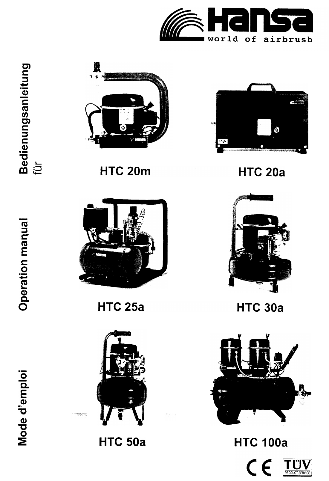
Kompressoren
Bedienungsanleitung
fijr
manual
Operation
for compressors
d’emploi
Mode
pour compresseurs
Page 2
Operation Manual
Page 3

-
Table
of~Contents -
ENGLISH
Introduction . . . . . . . . . . . . . . . . , . . . . , . . . . . .
Preface
Useasintended
Notes of warning and paragraph formats
Compressor nameplate
Guarantee
Supplier’s address.
Important Notes
General safety instructions
Environmental protection
Transportation
Before You Begin
Unpackdevice
Check package for completeness
Installation
.................................................
..........................................
.......................
................
...............................................
........................................
,
........
..................................
...................................
............................................
..........l
............................................
...............................................
.........................
.................,...
.............................
..................
.1-.
-...m
. . . . 3
3
3
4
4
5
5
7
7
8
8
9
9
9
9
Fillupoil
Drainoil
Initial Operation
Setting the operating pressure
Motor protection switch
Switching the compressor off
Maintenance
Weekly
Monthly ................................................
Quarterly or six-monthly
Failure List
Technical Data ,
Technical compressor data
HTC20m
HTC20a
...............................................
.................................................
............
..............................
...................................
...............................
..........,.
................................................
...................................
....
............
,
n
....................
,
.......................
...................
,
...........................l.....
.................................
..............................................
...............................................
10
12
13
14
15
15
17
I7
17
20
21
23
23
25
27
HTC25a
HTC30a
HTC50a
HTClOOa
...............................................
...............................................
...............................................
..............................................
29
31
33
35
Page 4

INTRODUCTION
Preface
Operation Manual - ENGLISH
This operation manual applies to compressor models HTC
HTC
tains valuable information on how to safely, properly and economically operate your compressor.
In your own interest, please observe the following points:
0
l
20a,
Use as intended
This compressor has been designed for the operation of com-
mercially available airbrushes.
20m,
HTC
Read this operation manual prior to initial opera-
tion and any maintenance work.
Observing the notes and instructions contained in
this manual is the only way that guarantees use as
intended.
Always keep the operation manual in the immediate
proximity of the compressor.
25a,
HTC
30a,
HTC
50a,
and HTC
IOOa.
It con-
Please observe the following notes:
The intended use includes the taking of all preventive
maintenance action described in this manual as well as
the proper disposal of all operating materials at the end
of their serviceable life.
Every application other than the use described in this
manual shall be considered not as intended. All conse-
quences shall be borne by the operator.
It is not allowed to change the compressor’s design or
construction.
Page 5
Introduction
Notes of warning and paragraph formats
In this manual, you will repeatedly come across certain notes of
warning and paragraph formats standing for the following types
of information:
Caution:
Note:
Note:
1.
0
This symbol makes you aware of any danger to
human
and/or
machine. Observe these safety
notes in your own interest.
This symbol marks helpful tips and other useful information.
This symbol appears every time the text mentions
operating or other materials for which legal processing and disposal rules exist to protect the environment.
Paragraphs preceded by a number mark instructions to
be worked through in the numbered sequence.
Paragraphs preceded by a dot refer to general lists.
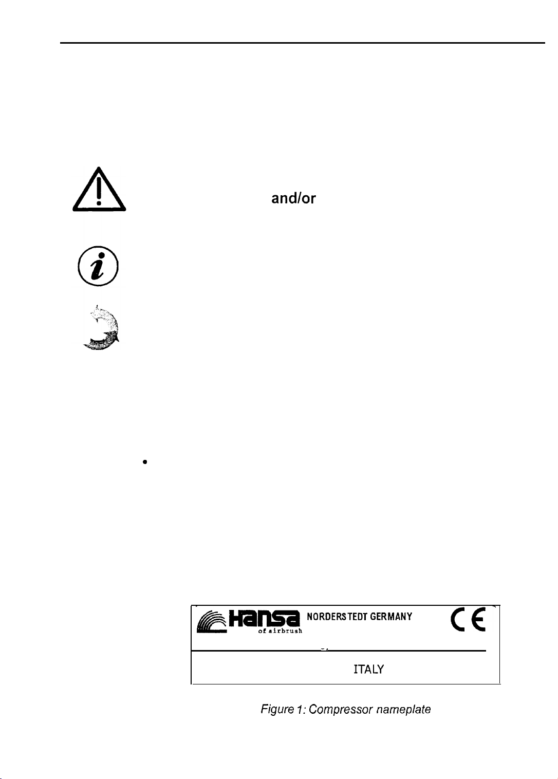
Compressor nameplate
The nameplate attached to the compressor displays information
about the compressor type, serial number, pressure rating,
model year and manufacturer.
world
MOD.HTC 20M
Manufactured by
WERTHER INT.CADE (R.E)
NORDERSTEDT GERMANY
of
airbrush
S/N 428492 L. 1
-’
ITALY
Figure I: Compressor nameplate
YEAR M/l997
BAR 6
Page 6

Guarantee
Operation Manual - ENGLISH
Hansa-Technik
mance of the device.
The guarantee period is 12 months, starting on the day of purchase.
The guarantee shall only be performed if the receipt is sent in
with the device to Hansa-Technik GmbH. We will remove all defects or damages caused by material or production failures.
The guarantee shall be performed by repair or replacement of
defective parts according to our best choice.
Damages to wearing parts as well as damages caused by improper use or maintenance action shall be excluded from the
guarantee.
Supplier’s address
GmbH
guarantees perfect quality and perfor-
.
Hansa-Technik
Oststr. 67
D-22844 Norderstedt - Germany
Telephone
Telefax
E-mail:
Internet:
+49-40-526
hansa@on-line.de
http://www.hansa-airbrush.de
GmbH
+49-40-
526 58-O
58-l 10
Page 7

Operation Manual
IMPORTANT NOTES
General safety instructions
The compressor must only be installed in dry rooms and protected against dampness and dust.
The spraying of combustible fluids constitutes a fire hazard and/
or a risk of explosion. Only use in well-aired rooms.
Install the compressor such that it can take in enough air at any
time. It may overheat otherwise.
Safety and protective devices on or in the compressor must not
be modified or disabled.
-d~ENGLISH
Immediately disconnect the device if you detect any unusual
sounds or smells during operation. Contact a specialised workshop if necessary. The compressor must only be restarted when
it has been put back into proper working order.
Repairs must only be made by qualified and trained persons.
Switch off and unpressurise the compressor prior to any mainte-
nance work.
The device has been designed for an operating voltage of
50Hz.
stalled and secured wall outlet.
The wall outlet to which the device is connected must be easily
accessible so that you can quickly disconnect the compressor
from the mains if and when required.
It is mandatory that power be supplied via a properly in-
23OW
Page 8

Important Notes
Environmental protection
Disposal of compressor oil must comply with your local authorities’ regulations.
At the end of its serviceable life, the compressor too is to be disposed in compliance with legal regulations.
Transportation
Drain all the oil from the compressor if you wish to transport it
(forwarder, P.O., etc.) any time after initial installation and setup.
You otherwise run the risk of oil escaping or getting into the
pression
Catch the oil to be drained off in a suitable container.
Hansa-Technik
by the transportation or dispatch of oil-filled compressors.
chamber thus damaging the device.
GmbH
shall not be liable for damages caused
co-
Page 9
Operation Manual - ENGLISH
BEFORE YOU BEGIN
Unpack device
After unpacking, check the compressor for any transport damages.
0
2
0
Check package for completeness
Note:
Note:
Check whether the delivery package was complete. Apart from
the compressor, the package should contain the following parts:
Keep the packing material so that you can reuse it
for any later transportation.
Dispose of the packing material in compliance with
the applicable regulations if you no longer need it.
I
bottle of oil (2 bottles for model HTC
1 screw-on filler tip for the oil bottle (2 filler tips for mod-
el HTC
plug-type connectors;
1 air filter (two filters for model HTC 1
IOOa);
IOOa);
OOa),
and
installation
of the appropriate size.
The room temperature should be no higher than 35”
with fresh air.
1 plastic tube for draining the condensation water off
the fluid container (applies to models HTC 30a and
HTC
Install the compressor on an even surface in a well-aired room
Provide extra ventilation if the room is not sufficiently supplied
50a
only).
C.
Page 10
Before
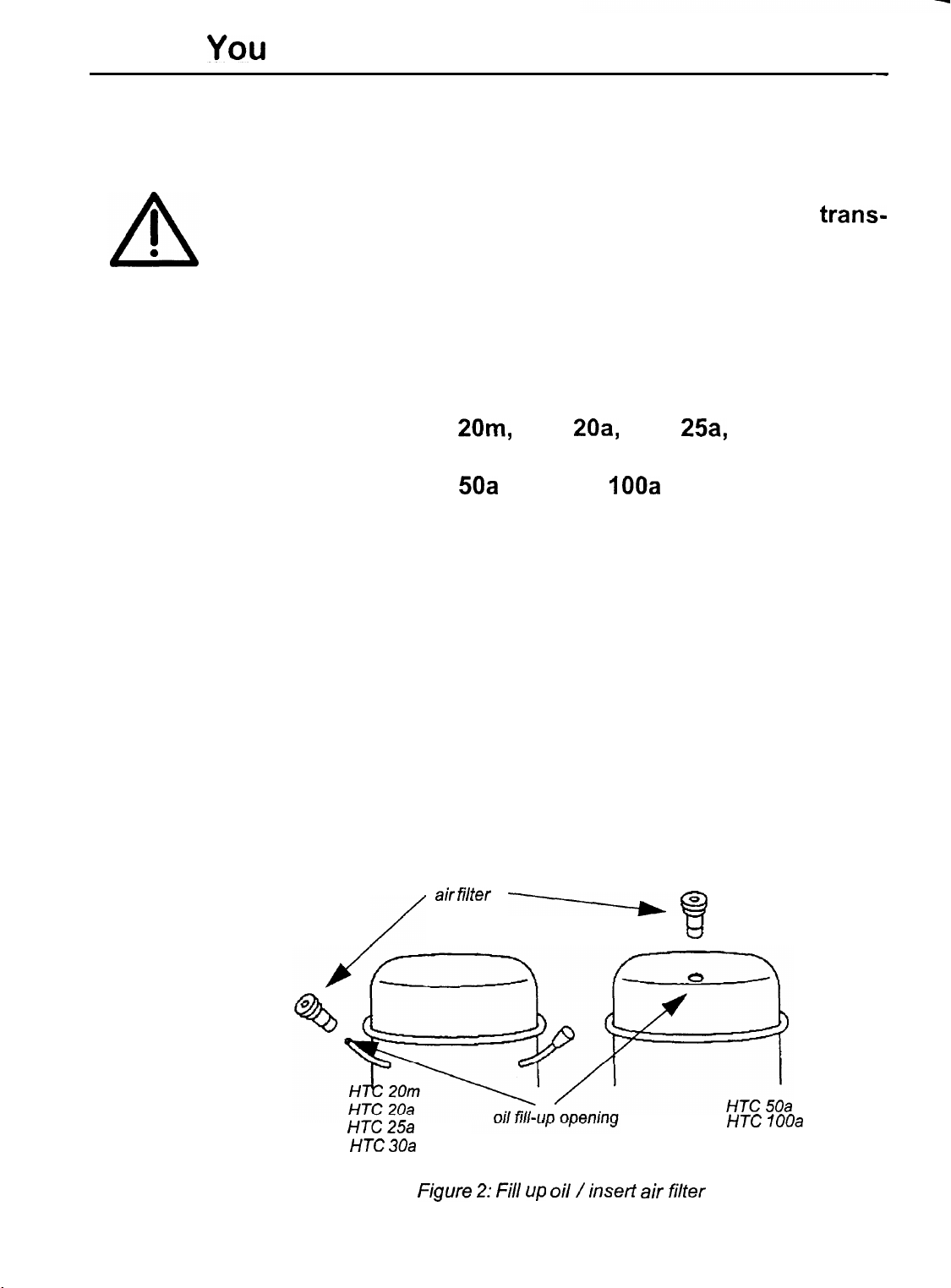
Fill up oil
You
Begin-
-
Caution:
I.
2.
3.
There is no oil in the compressor during
trans-
portation. This avoids oil getting into the com-
pression chambers which would damage the de-
vice. You therefore have to fill up oil before you
put the compressor into operation for the first
time. The device might otherwise be damaged.
Models HTC
20m,
HTC
20a,
HTC
25a,
and HTC 30a
Remove the cap from the intake fitting.
Models HTC
50a
and HTC
IOOa
Remove the cap from the opening in the lid of the motor.
Screw the filler tip (part of delivery package) on the
open oil bottle and cut off the end.
Connect the compressor to the appropriate power
source.
4.
5.
Turn the ON/OFF switch to I (ON) to switch on the com-
pressor.
Attach the oil bottle to the intake fitting or the opening in
the lid of the motor resp. (depending on your model).
air filter
/
HTC 25a
HTC 30a
Figure 2: Fill up oil / insert air filter
-----be
k?
HTC 100a
The motor will now suck in the oil.
Page 11
Operation Manual - ENGLISH
6.
7.
8.
Caution:
Note:
Switch off the motor when about
in.
Check the oil level via the oil-level gauge.
Repeat the above steps if the oil level is not correct yet.
Make sure that the oil level does not exceed the
maximum reading. Drain any excessive oil if it
does; see ,,Drain oil“ on page 12.
It is mandatory to use the compressor oil supplied by
ranty claims.
Keep any remaining oil for later replenishment.
Hansa
exclusively to maintain your war-
2/3
of the oil have run
9.
The compressor is now ready to operate. Make sure that it stays
in its horizontal position because non-compliance may cause oil
to get into the compression chamber which might cause damage.
When filling up is complete, insert the air filter (part of
delivery package) into the intake fitting or the opening
in the lid of the motor (depending on the model you
use), see figure
,,Fill
up oil / insert air filter” on page IO.
Page 12

Before You Begin
Drain oil
Drain oil every time you wish to transport the compressor or if
you filled up too much oil by mistake.
Caution:
1.
2.
3.
It is mandatory to drain off the oil prior to any
transportation or dispatch of the compressor
because non-compliance may cause oil to escape or to get into the compression chamber
which might damage the device.
Unscrew the oil-level gauge.
Let the oil run off into a suitable container.
Screw the oil-level gauge back in and check for safe
and proper seat.
Page 13
INITIAL OPERATION
Operation Manual - ENGLISH
Caution:
1.
Caution:
2.
The motor starts building up the operating pressure which takes
about 40 to 240 seconds, depending on the model you use.
HTC
20a,
Check whether there is enough oil in the
pressor
time.
Verify that there is enough oil in the compressor.
Proceed as described in section
page 10 if there is no or not enough oil in the
compressor.
Set the ON/OFF switch to I (ON).
HTC
before you start the machine for the first
,,Fill
up oil” on
25a,
HTC
30a,
HTC
50a,
HTC
IOOa
com-
These compressors are equipped with an automatic pressure
monitoring feature which will automatically switch off the motor
when it has built up the maximum pressure.
The motor restarts automatically when the pressure drops to
four (or six) bar after air bleeds from the pressure vessel.
HTC 20m
This model activates a safety valve when the pressure has built
up to its maximum of six bar. Any overpressure escapes through
this safety valve producing a soft hissing sound.
Page 14

Initial Operation
Switch off compressors of this type to avoid
their overheating during no-operation intervals.
All compressors are equipped with a safety
valve which must neither be removed nor modified in any way. Have a qualified workshop repair or exchange the safety valve.
I
0
A
Caution:
Setting the operating pressure
Use the pressure controller to set the required operating pressure. Monitor the pressure reading via the pressure gauge.
1.
2.
Pull up the rotary switch.
To increase the pressure
Turn the control button clockwise.
To reduce the pressure
Turn the control button anti-clockwise.
3.
Push the rotary switch back in (down) when you have
set the correct operating pressure.
Figure 3: Setting the operating pressure
Page 15

Motor protection switch
All of the compressors are equipped with a motor protection
switch that avoids damage to the motor by automatically switching it off in instances of overload or overheating.
Proceed as follows if the motor shuts down during normal operation:
Operation Manual - ENGLISH
1.
2.
Set the ON/OFF switch to 0 (OFF) and allow the machine to cool off for about 30 minutes.
Restart the compressor after about 30 minutes.
Switching the compressor off
Switch off the compressor at longer idle periods.
Also switch off the machine when it seems to be
not operating, i.e. when the motor is not running. This situation occurs when the motor has
built-up maximum pressure thus activating the
automatic monitoring device. In this case, the
motor is in stand-by mode which means that it
will restart immediately when the pressure falls
below a specified value.
A
I
0
Caution:
Set the ON/OFF switch to 0 (OFF) to switch off the motor.
Page 16

MAINTENANCE
To extend the life of your compressor, we recommend that you
take the preventive maintenance action below at the suggested
intervals.
Operation Manual - ENGLISH
Weekly
l
2
0
Caution:
Check the oil level
Note:
Check the oil level via the oil-level gauge once every week
(compressor off) and fill up oil if necessary, see
page 10.
Switch on the compressor and remove the air filter from the air
Disconnect the machine
all maintenance work.
Fill up oil while the motor is running.
from the mains prior to
,,Fill
up oil“ on
Monthly
intake fitting or the opening in the lid of the motor (depending on
the model you use). Fill up the required amount of oil. Check the
oil level again via the oil-level gauge. Then insert the air filter in
the relevant opening again.
Visual inspection
Visually inspect the machine once every month taking particu-
larly care to find any loose connectors or screws and verifying
the general condition of the pressure hoses.
Page 17

Page 18

Operation
Draining water from the water trap
Jl/lan.uq! -
ENGLISH
a
2
0
Note:
Drain the condensation water from the water trap once every
month (or more frequently if required).
Turn the rotary button clockwise, push it in and hold it until all
water has been drained off. Turn the rotary button anti-clockwise when there is no more water coming. Make sure that the
tank is under pressure.
Use the appropriate means, e.g. a piece of cloth, to
catch any condensation water escaping.
Figure 5: Drainage of water from the water trap
Page 19
Mainte.nance
_.
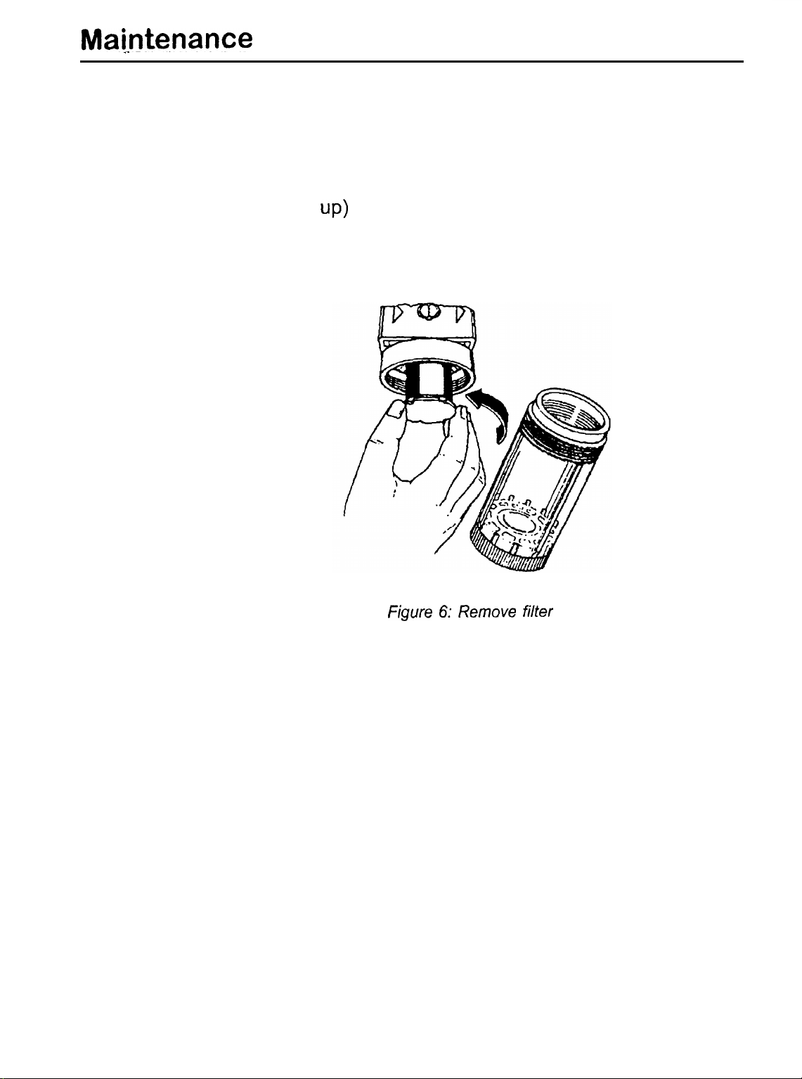
Quarterly or six-monthly
Replace the filter
Replace the filter’every 3 to 6 months (depending on how much
it has clogged
up)
Figure 6: Remove filter
Page 20

FAILURE LIST
Operation Manual - ENGLISH
Caution:
Problem
The motor of the
pressor does not start
com-
Immediately switch off the power supply to the
device if any failures occur.
Have only trained and qualified persons do any
repairs.
Table I: Failure List
Possible Cause
No power
Wire failure or lose
trical
connections
Too much oil
Too much tank pressure,
pressure control switch tank
turned motor off
elec-
Corrective Action
Check fuse and plug
Specialist’s workshop
Drain oil
Let some air out of the
The compressor is
king but builds up no
pressure
The compressor is
king but does not build up
the maximum pressure
The compressor
ches off during operation
wor-
wor-
swit-
Cap not removed from
the intake tube
Air filter clogged up
System leaks
System leaks Check hoses and con-
Wrong pressure control
switch settings
Check valve defect or
blocked
Motor overheated, motor
protection switch actua-
ted
Remove cap
Replace air filter
Check hoses and con-
nectors for leaks
nectars
Check settings, contact
specialist if required
Replace check valve
Switch off compressor,
allow motor to cool off
for leaks
Page 21

Failure List
Table I: Failure List
Problem
The compressor is
ning without any work
being done
The compressor does Pressure control switch
not start when the
sure falls below the
mum or does not stop at
max. pressure
The compressor
heats
run-
pres-
mini-
over-
Possible Cause
System leaks
defect
Oil level not ok
Wrong type of oil
Air filter clogged up
Corrective Action
Check hoses and con-
nectars for leaks
Have specialist replace
the pressure control
switch
Check oil level and fill up
if necessary
Drain oil and replace by
Hansa
sors
Replace air filter
oil for compres-
Note:
Room temperature too
high or not enough air
Compressor overload Check whether the com-
Provide enough fresh air
pressor matches the de-
mands
The above list of possible failures and problems
does not claim to be comprehensive.
Page 22
Operation Manual - ENGLISH
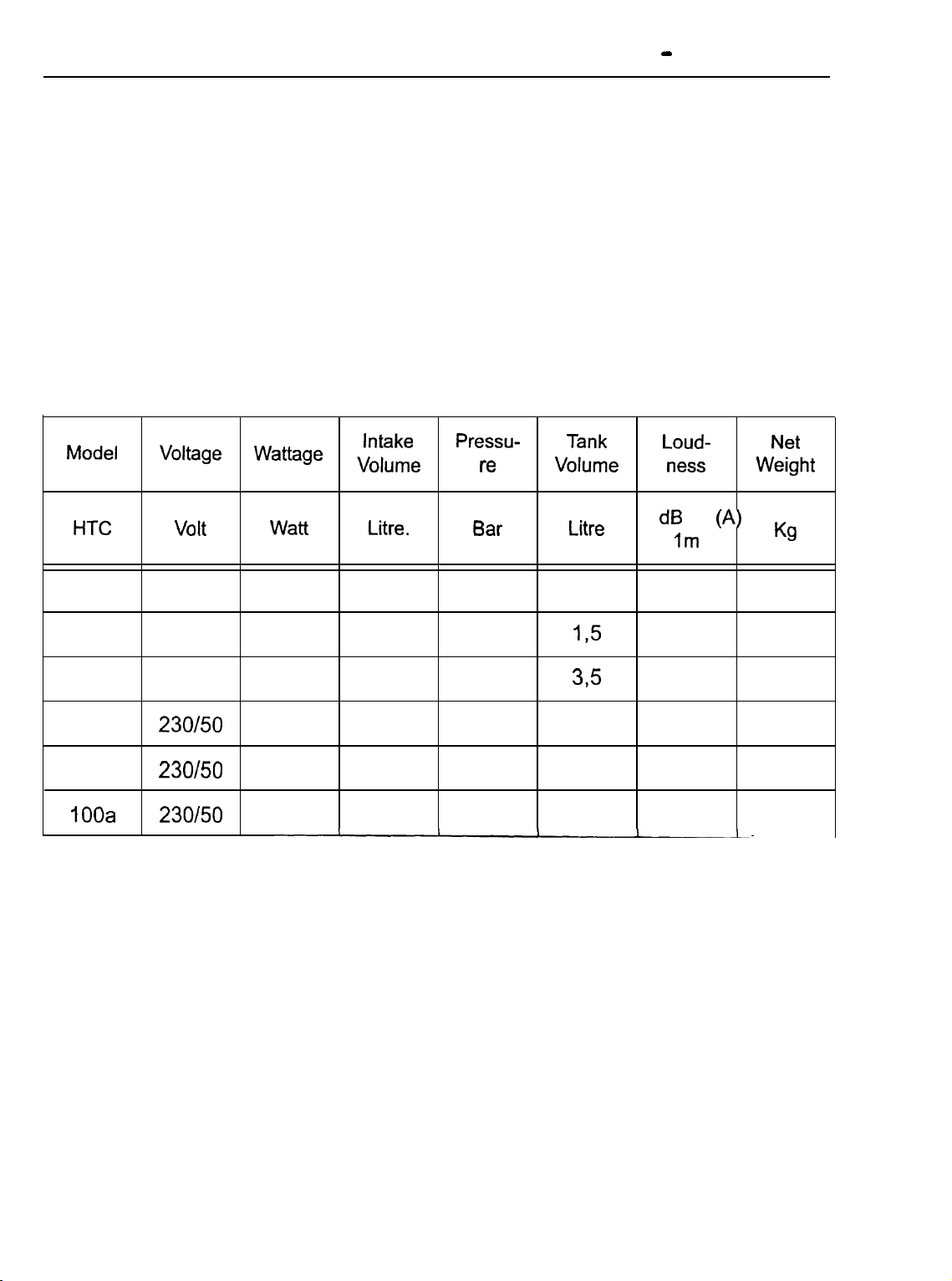
TECHNICAL DATA
Technical compressor data
The table below lists the ratings of the different compressor
types.
Table 2: Technical Data
Model
HTC
20m
20a
25a
30a
50a
IOOa
Voltage
Volt
230150
230150
230150
230/50
230/50
230/50
Wattage
Watt
135
135
135
200
340
680
Intake
Volume
Litre.
20
20
20
30
50
100
Pressu-
t-e
Bar
6
6
6
8
8
8
Tank
Volume
Litre
1
1,5
395
9
15
24
Loud-
ness
dB
Im
38
38
38
40
43
43
tA)
Weight
Net
Kg
12
14
16
18
24
39
Page 23
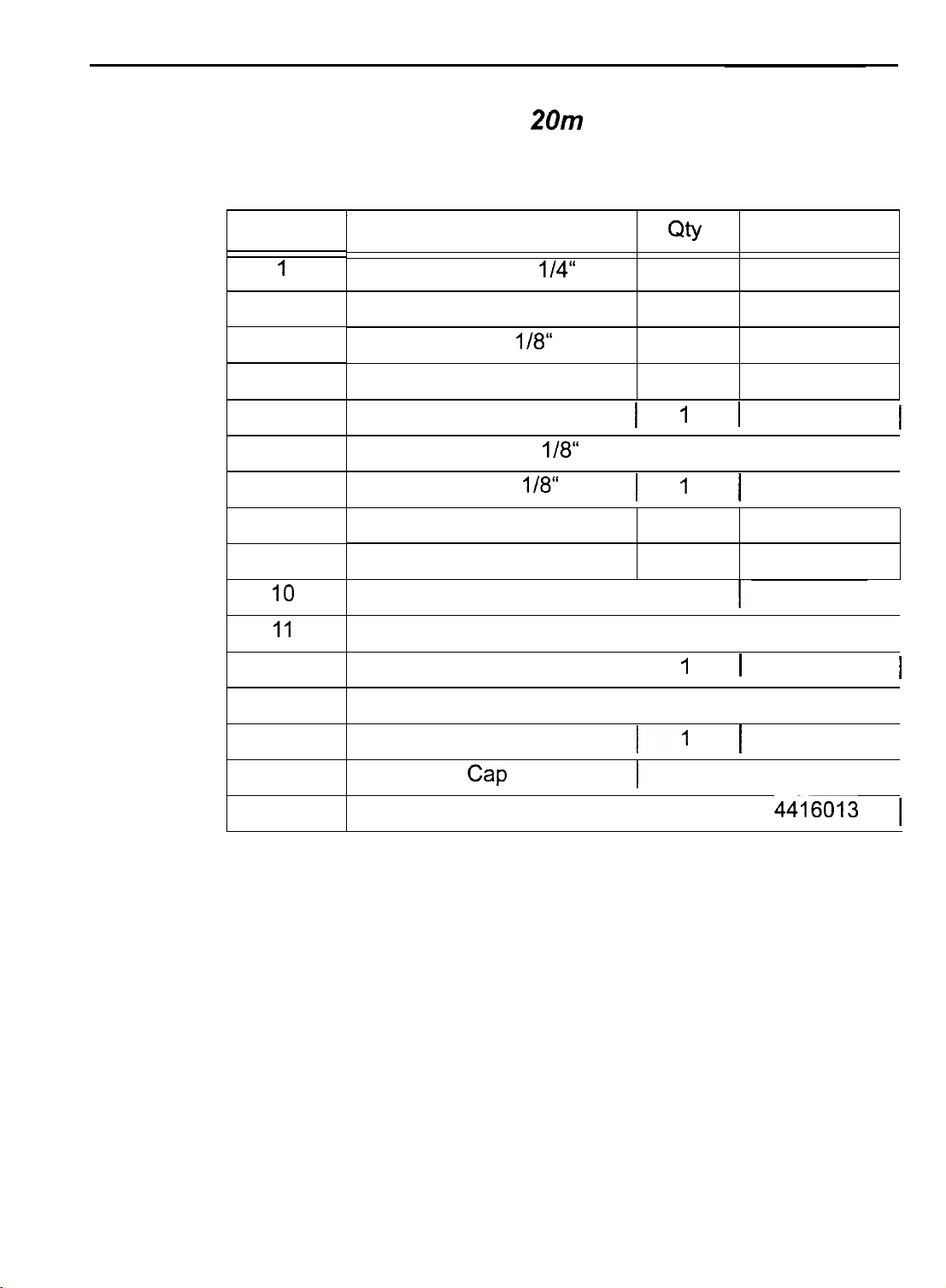
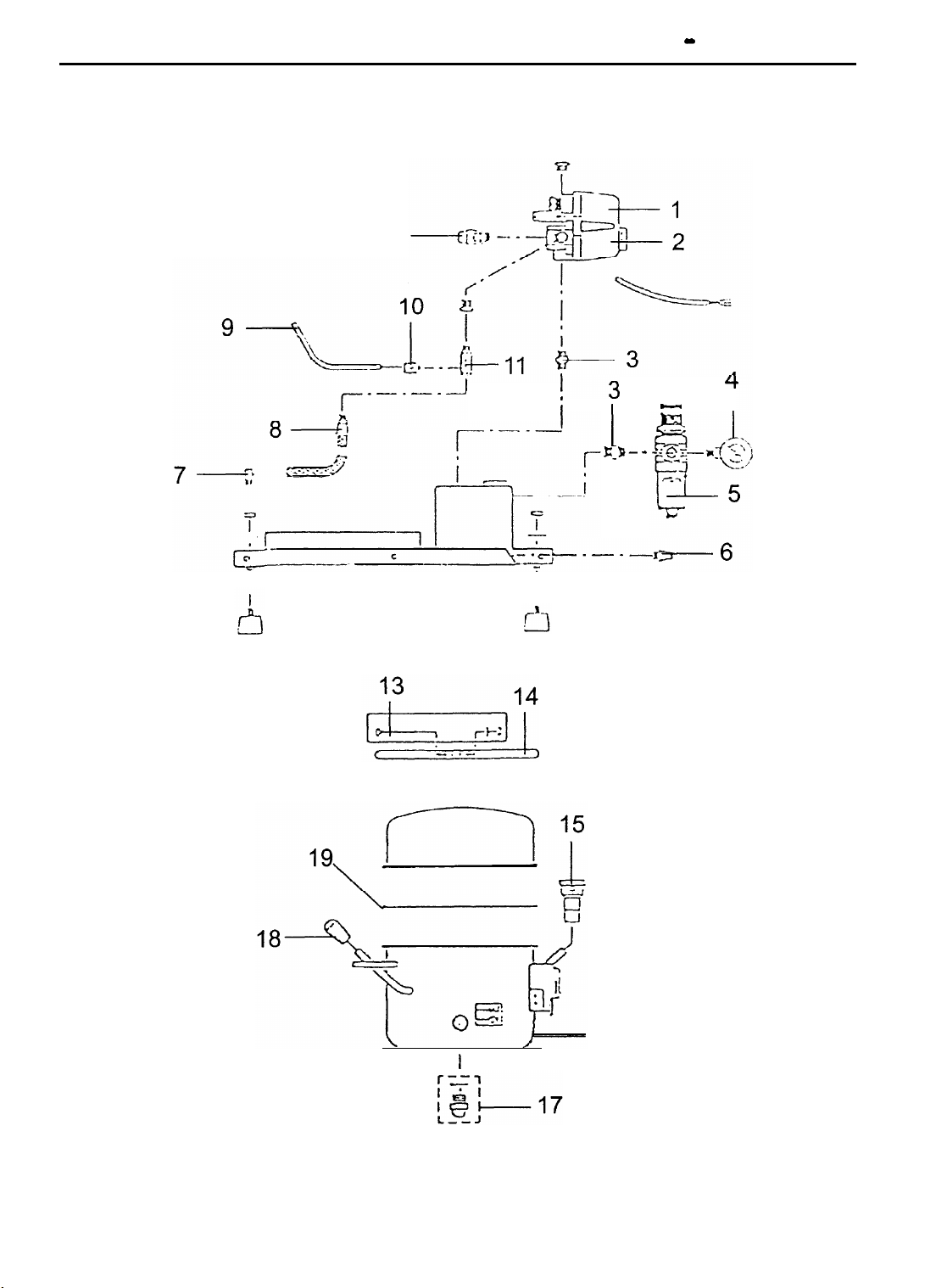
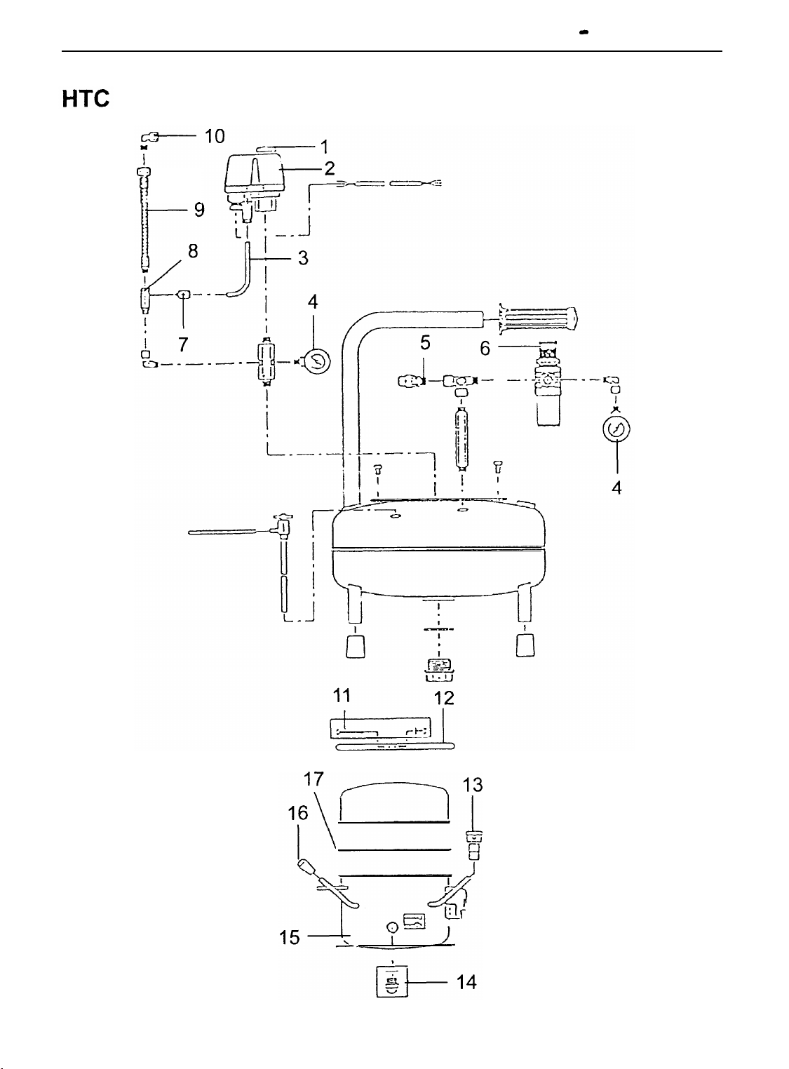
Technical Data
Spare parts list for HTC
Number
1
2
3
4
5
6
7
8
9
10
11
12
I
Double nipple
Pressure controller and filter
Pressure gauge
Pressure hose
Name
Rilsan hose
Clip
Drain plug
Safety valve
ON/OFF switch
Screw for clip
Motor lid clip
Air filter
20m
l/8“
l/8“
l/4“
10 bar
l/8“
Qty
1
1
1
1
I
1
1
I
1
I
1
1
1
I
1
I
I
1
Part No.
4416014
4416073
4416074
4416009
1
4416007
4416006
I
4416015
I
4416008
4416010
4416077
1~
4416012
I
1
4416072
1
I
I
I
I
1
13
14
15
16
Motor
Oil-level gauge
Cap
Motor lid seal
1
I
1
I
1
I
4416001
I
4416071
I
4416016
I
44-16013 1
I
I
I
I
Page 24

HTC 20 m
Operation Manual - ENGLISH
3
I--
4
fl
5
8
Page 25

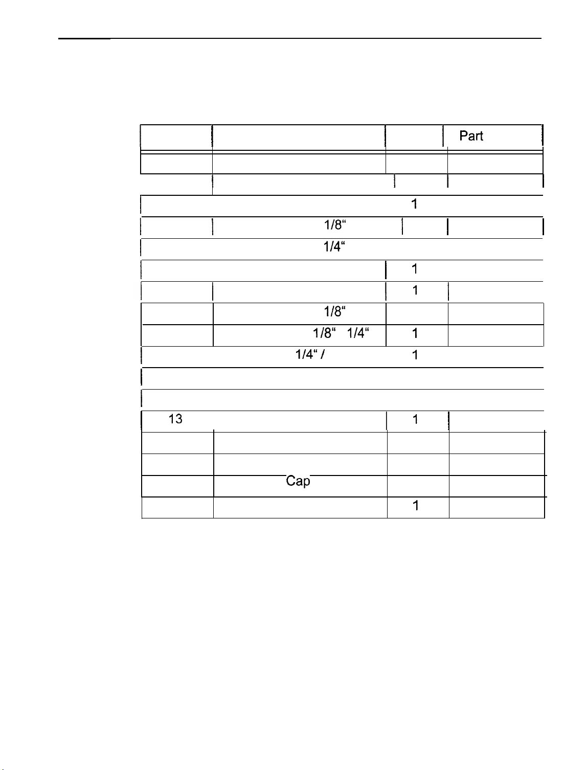
Technical Data
Spare parts list for HTC
Number
I
I
1
2
3
4
5
6
7
8
9
10
Pressure control switch
I
Double nipple
Pressure gauge
Pressure controller and filter
I
Pressure hose
Hose connector M5
Name
ON/OFF switch
Drain plug
Clip
Rilsan hose
20a
l/8“
l/8“
l/4“
10 bar
l/8“
I
I
Qty
1
2
1
1
1
1
1
1
1
Part No.
4416018
I
4416014
4416074
4416073
4416015
4416007
I
4416006
4416019
4416040
I
I
11
12
13
14
15
16
17
18
19
Check valve
Safety valve 114"
Screw for clip
Motor lid clip
Air filter
Motor
Oil-level gauge
Cap
Motor lid seal
118“
1
1
1
1
1
1
1
1
1
4416017
4416079
4416077
4416012
4416072
4416001
4416071
4416016
4416013
Page 26
HTC 20a
Operation Manual - ENGLISH
I2
I3
.
I
I
I
E-E,- -
4
-
I
I
I6
Page 27

Technical Data
Spare parts list for HTC 25a
Number
I
Name
1
2
Pressure control switch
I
Pressure
Pressure controller and filter
ON/OFF switch
Bracket 118“ 118“
gauge
l/8“
10 bar
Drain plug
Bracket
Pressure hose 235 mmm
Rilsan hose
l/4”
l/8“
6.3
QtY
1
I
I
1
1
1
1
1
1
Part No.
4416018
I
1
4416036
4416074
4416073
4416015
4416035
4416038
4416019
I
I
1
I
17
18
19
Oil-level
Motor lid seal
gauge
Cap
1
1
1
4416071
4416016
4416013
Page 28

Operation Manual - ENGLISH
HTC
25a
.-.-r
e-10
.
..-.-. -
7
.
$
I5
Page 29
Technical Data
Spare parts list for HTC 30a
1
Number
1
Name
1
Qty
1 Part
No.
1
1
I
I
2
3
I
4
5
I
6
I
7
8
9
IO
I
II
I
12
I
13
I
14
1
Pressure control switch 1 1
I
1
Pressure gauge
I
Pressure controller and filter
I
I
I
I
I
I
ON/OFF switch
Rilsan hose
Safety vavle
Hose connector M5
Check valve
Pressure hose I
Bracket
Screw for clip
Motor lid clip
Oil-level gauge
l/4“ /
Air filter
l/8”
10 bar 1 2
l/4”
l/8“
/8”
l/4“
6.3
1
4416041
I
I
1
I
I
I
1
I
I
I
1
I
1
I
1
4416039
I
1
4416074
4416079
I
4416073
I
4416040
I
4416017
4416038
4416035
I
4416077
I
4416012
I
4416072
I
4416071
1
I
1
I
I
I
I
I
I
I
15
16
17
Motor
Cap
Motor lid seal
1
1
I
4416030
4416016
4416013
Page 30
30a
c
‘I
I:
Operation Manual - ENGLISH
-
Page 31

Technical Data
Spare parts list for HTC 50a
Number
I
2
I
3
4
5
6
7
9
10
11
12
13
Name
ON/OFF switch
Pressure control switch
I
Pressure
Pressure controller and filter
Pressure hose
gauge
Safety valve
Extension
Check valve
Hose connector
Rilsan hose
Motor lid clip
1/8” IObar
114“
I /4“
118“
Air filter
Plug
l/8“
M5
QtY
I
I
3
2
1
1
1
1
1
1
I
I
Part No.
4416041
I
44 I 6074
4416073
4416079
4416059
4416038
4416017
I
4416040
4416039
4416057
4416072
4416082
I
,
I
14
15
16
17
Oil-level
Motor lid seal
Screw for clip
gauge
Motor
1
I
1
1
4416071
4416050
4416056
4416077
Page 32

HTC 50a
Operation Manual - ENGLISH
~7~kq---,:
16
i
l$--==
! u
I
II
i-l
----------\
..-.-
c
&I2
f
t.
11
13
r-+--‘-l
\
Page 33

Technical Data
Spare parts list for HTC 700a
Number
I
I
1
2
3
4
5
6
7
8
9
IO
11
12
13
Name
Pressure control switch
ON/OFF switch
Safety valve
Pressure gauge
Check valve
I
Pressure hose
Pressure hose
Pressure controller and filter
I
Rilsan hose
Drain plug
Extension
Screw for clip
Motor lid clip
118“
1 Obar
318”
l/8“ l/8“
l/8” 118“
l/4“
l/4“
I
I
Qty
I
1
3
1
1
1
I
I
1
2
1
2
Part No.
4416018
4416079
4416074
4416063
4416019
I
4416062
4416061
4416060
4416059
4416073
4416077
I
4416057
I
I
14
15
16
17
18
Air filter
Plug
Oil-level gauge
Motor
Motor lid seal
2
2
2
2
2
44 16072
4416082
4416071
4416050
4416056
Page 34

TC
Operation Manual - ENGLISH
IOOa
8
12
18,
---------->
;t-rq-c+5
c
-
-is
e-5
r”‘l
13
14
Page 35

Index - ENGLISH
C
compressor
switch off 15
switch on 13
compressor nameplate 4
contents of delivery package 9
E
environmental protection 8
F
failures 21
first start of operation 9
G
guarantee 5
I
initial operation 13
M
machine
check delivery package 9
install 9
unpack 9’
maintenance 17
check oil level 17
drain water from water trap 19
0
oil
drain off 12
fill up 10
operating pressure
set 14
P
preface 3
S
safety instructions 7
spare parts
HTC 20m 24
HTC 20a 26
HTC 25a 28
HTC 30a 30
HTC 50a 32
HTC
supplier’s address 5
IOOa
34
T
technical data 23
transportation 8
lJ
use as intended 3
replace filter 20
visual inspection 17
motor protection switch 15
N
notes of warning and paragraph
formats 4
 Loading...