

Hanover ERIC++ Installation And Operation Manual
Hanover Displays Ltd Southerham House, Southerham Lane, Lewes BN8 6JN Tel: +44 (0)1273 477528 540114-8
ERIC++ Controller
Installation and Operation Manual
(Software version V1.23)
ERIC++ Controller – Installation and Operation Manual
Please note that this document is subject to continual updating: please ensure
you are using the latest edition.
This edition: 17 March 2015
© COPYRIGHT HANOVER DISPLAYS LTD 2015
The copyright of this document is vested in Hanover Displays Ltd and the document is issued in confidence for the
purpose only for which it is supplied. It must not be reproduced in whole or in part or used for tendering or
manufacturing purposes except under an agreement or with the consent in writing of Hanover Displays Ltd and then
only on the condition that this notice is included in any such reproduction. All trademarks are recognised.
540114-8 page 2 of 59 17/03/2015

ERIC++ Controller – Installation and Operation Manual
CONTENTS
GLOSSARY 5
1. Introduction 7
1.1 General 7
1.2 Scope of this manual 7
1.3 Brief history of Hanover controllers 8
1.4 System overview 8
1.5 Identification 9
1.6 Controller overview 10
1.6.1 Front view 10
1.6.1.1 Example of LCD display 11
1.6.2 Rear view 11
1.7 Technical information 11
1.7.1 Specification 11
1.7.2 System supply voltages 12
2. Installation 13
2.1 Standard positions for the controller are: 13
2.2 System wiring 13
2.2.1 Power 13
2.2.2 Communication 14
2.2.3 Multicomms 14
3. Operation 15
3.1 Getting started 15
3.1.1 Boot screens on power-up 15
3.2 Loading a database into the ERIC++ from Helen 15
3.2.1 Base station and Keylo data loader 15
3.2.2 Transferring the database to the Keylo dataloader using Helen 15
3.2.3 Transferring the database from the Keylo to the ERIC++ 18
3.3 Selecting the information to be shown on the signs 18
3.3.1 Destination code 18
3.3.2 Route code 19
3.3.3 Information code 19
3.3.4 Advert code 20
3.3.5 Lock code 20
3.3.6 Round trip (Aller-Retour) 20
3.4 Other configurations 20
3.5 Accessing other functions of the ERIC++ 21
3.5.1 Status options 22
3.5.2 Running the signs test 23
3.5.3 Dump data screen sequence 23
3.5.4 Load data 24
540114-8 page 3 of 59 17/03/2015

ERIC++ Controller – Installation and Operation Manual
3.5.5 Operating mode 24
3.5.6 Configuration options 25
3.5.7 System options 26
3.5.8 Port options 26
3.5.9 Sign options 26
3.5.10 Preview destination 26
3.5.11 HYVOX 27
3.5.11.1 Simulation mode 27
3.5.12 Configuration code option: TV 27
3.5.12.1 TV = 1 (for more details, please refer to TV entry in Appendix E) 28
3.5.12.2 TV = 2 (for more details, please refer to TV entry in Appendix E) 28
3.5.13 External input options 29
3.5.13.1 Emergency message 29
3.5.13.2 Blanking the sign (battery guard) 30
3.5.13.3 Displaying ‘Bus stopping’ 30
3.5.13.4 Information message 31
3.5.13.5 Destination VOX (Hanvox) audio message 31
3.5.13.6 E, I and EI values 31
3.5.13.7 Displaying ‘Bus reversing’ 32
3.5.14 Reset options 32
3.5.14.1 Factory lock code reset 33
3.5.14.2 Configuration reset 33
3.5.14.3 Factory reset 33
3.6 Firmware 33
3.6.1 Overview 33
3.6.2 ERIC++’s firmware version 34
3.6.3 Firmware update procedure 34
4. Troubleshooting 36
4.1 Overview 36
4.1.1 No display or backlight on controller 36
4.1.2 No communication or required information not displayed on signs 36
4.1.3 List will not load into ERIC++ controller 37
4.1.4 ERIC++ loads list correctly but shows ‘Bad Destination or Bad Route’ 37
4.1.5 Sign test function 37
4.1.6 Information code on controller screen shows ‘??’ 38
4.1.7 Advert code on controller screen shows ‘??’ 38
4.1.8 On-screen response erratic when using keypad 38
4.1.9 Faults not listed here 39
4.2 If troubleshooting does not solve the problem 39
4.3 Hanover Technical Support 39
4.3.1 United Kingdom 39
4.3.2 United States of America 39
5. Queries, FAQs and other information 40
540114-8 page 4 of 59 17/03/2015

ERIC++ Controller – Installation and Operation Manual
5.1 Overview 40
5.2 Queries 40
5.3 Frequently asked questions 40
5.4 Other information 41
5.4.1 Replacing an ERIC++ controller with a DG3 controller 41
5.4.2 Replacing an ERIC++ controller with an EG3 controller 42
Appendix A: Cable Assembly Drawing 43
Appendix B: System Options 44
Appendix C: Protocols – Port Options 46
Appendix D: Sign Options 50
Appendix E: Configuration Code Options 51
540114-8 page 5 of 59 17/03/2015

ERIC++ Controller – Installation and Operation Manual
GLOSSARY
Explanations relate to the use of the word in this manual and other Hanover publications; the word or
phrase may have other meanings elsewhere.
browse - move up / down a list of options in order to find the desired item
controller - on-bus device used by driver to populate signs with text and graphics which have been
prepared using Helen software
data loader - early controllers were able to be used to load other controllers with data; the ERIC++ simply
uses a Keylo
database - information uploaded to a controller from a standard PC using Helen display-editing software.
Includes destination / route number information, advertising and other service information (eg emergency
announcements, school bus messages etc.)
(destination) code - the number used to identify a particular destination from a list. Each code must be
unique within the list and can contain up to 10 alphanumeric characters. It is the code to be entered on the
driver’s controller
(destination) list - an electronic list of information for one or more routes / destinations specified by the
Helen software and deployed via a controller on a sign
display - sign
e-prom - type of memory chip that retains its data when its power supply is switched off
Hancis - The Hancis Audio Video Computer provides the operator with video, audio and GPS within a
single unit and can be placed anywhere within the vehicle. It can be interfaced to TFTs which give high
quality display and functionality for on-bus passenger information
HELEN - Hanover Extended List Editor for DestinatioN Displays - a software tool used to create and edit
text, graphics and destination lists on a pc as they will appear on a Hanover’s sign
HTC - Hanover Transport Computer - a location aware media player specifically designed for use within
the public transport passenger information sector
IBIS - communications standard - mostly used on buses with German equipment
LED - light-emitting diode: most Hanover signs use LED technology
Mini fit (connector) - two-piece pin and socket interconnection where cylindrical spring-metal pins fit into
cylindrical spring-metal sockets. The pins and sockets are held in a rectangular matrix in a nylon shell.
multi-drop - connection of several devices to a single communication or power line (in 'daisy chain'
configuration)
RS485 - the main electrical communications standard used for communications between signs and
controller
RTC - Real Time Clock
sign - equipment used to present text and graphics for viewing by passengers, usually located on the front,
side or rear of, or inside a bus
Super-X - display control language for determining the way text is presented on a sign
540114-8 page 6 of 59 17/03/2015
ERIC++ Controller – Installation and Operation Manual
Manual covers
Section 1
Introduction to the manual (also contains technical information for the controller) and the
ERIC++
Section 2
Installation
Section 3
Operation
Section 4
Troubleshooting
Section 5
FAQs which address the more common problems and queries
Manual does not cover
The destination or in-bus signs themselves:
The installation and service of the signs: for more details, please refer to the LED destination
display - installation and service manual (ref. 540156)
Technical specification for individual signs: this is provided separately for each variant
The use of the Helen display-editing software for composing messages for the signs: for more details,
please refer to the Helen v3.3 display-editing software - operating manual (ref. 540125)
Introduction
1.
1.1 General
The best understanding of Hanover's ERIC++ controller will be gained by reading the complete manual but this is not always practicable for the user. The document has therefore been written in a modular
fashion in order to allow users to refer only to those parts of it they need: topics should thus appear
relatively self-contained. However, there are several useful cross-references, both to other points within
this manual, to other Hanover manuals and to external documents as appropriate. Accordingly, when
consulting this document using a pdf reader, it is helpful to have the 'Back' (or 'Previous') and 'Next' (or
'Skip' / 'Forward') buttons enabled to obtain maximum benefit from the intra-document cross-references.
For example, in Adobe Reader, press F8 to view the toolbar if it is not already visible. Right-click on a
blank section of the toolbar and, in the 'Page Navigation' menu, please ensure that 'Previous View' and
'Next View' are ticked.
Reference is made to the LED destination signs and to the Helen software used with the ERIC++: detailed
manuals are available for these from Hanover.
Destination signs for buses and coaches are normally used on the front, side and rear of the vehicle. This
practice is so widespread that Hanover often uses 'front, side and rear' to describe equipment used in
those positions. However, it is important to stress that any sign can be used anywhere on a vehicle,
subject to the relevant electrical / communications connections being made.
Information about the location of the controller is provided in section 2.1 Fitting the controller.
1.2 Scope of this manual
This manual covers the installation and operation of the Hanover ERIC++ controller. It also has
troubleshooting and FAQs sections which address the more common problems and queries.
Hanover produces many bespoke and custom systems - for example, with special wiring adaptations or
software features. The ERIC++ controller will work well as part of a networked system (including with
third-party hardware) but users are advised to consult their system-specific documentation and / or consult
Hanover (please refer to section 4.3 Hanover Technical Support) where necessary.
540114-8 page 7 of 59 17/03/2015
ERIC++ Controller – Installation and Operation Manual
Year
History
c. 1989
The first ERIC (Electronic Route Information Controller) had an extensive keypad and four
serial ports.
1991
The original and black front DERIC (Diminished Electronic Route Information Controller) was
introduced with 128k flash memory, later expanded to 1Mb.
1999
The grey front DERIC+ was introduced. As a more versatile controller, it boasted faster
loading and could also be used as a data loader. The DERIC+ deployed a standardised
communication plug-in and allowed firmware updates directly via a serial port instead of
having to change an e-prom.
2003
Similar in many respects to the DERIC+, the ERIC+ introduced a graphic display to controllers
and could be supplied with a 4Mb memory.
2005
The ERIC++ had the same features as the ERIC+ but contained a different and faster
processor.
2011
The DG3 (DERIC Generation 3) was introduced, bringing a larger (more pixels) graphic
display and USB connectivity. It worked across a wider voltage range (9-36V) than the DERIC
(24-36V). An extra key was added to the front panel and it was generally easier to use. The
DG3 cannot be used as a data loader however, although the USB facility renders the loss of
this feature largely irrelevant.
2014
The arrival of the EG3 (ERIC Generation 3) heralded USB connectivity for the ERIC
controllers family, has up to four secondary communications ports and a still faster processor.
It also has Ethernet connectivity.
> 2014
DG3 will have Ethernet connectivity in future versions.
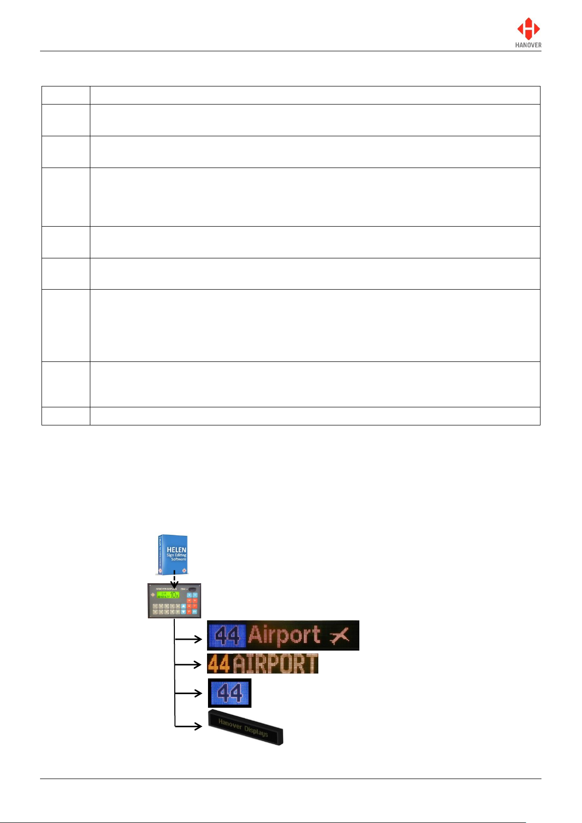
Destination sign (front)
Destination sign(s) (side)
Destination sign (rear)
ERIC++ controller
Internal LED sign(s)
1.3 Brief history of Hanover controllers
1.4 System overview
The ERIC++ is a vehicle based controller that controls how the information is presented on destination and
in-bus signs located on buses and coaches. An on-board computer can also be used to deliver full colour,
high resolution pictures, video clips and announcements. It has a key panel operation with all configuration
settings hidden behind a user-programmable lock code. The ERIC++ can be used to show route /
destination details, advertising and other information, all programmed using the Helen display-editing
software.
540114-8 page 8 of 59 17/03/2015
Figure 1 - typical controller / signs configuration. Each unit is powered individually.
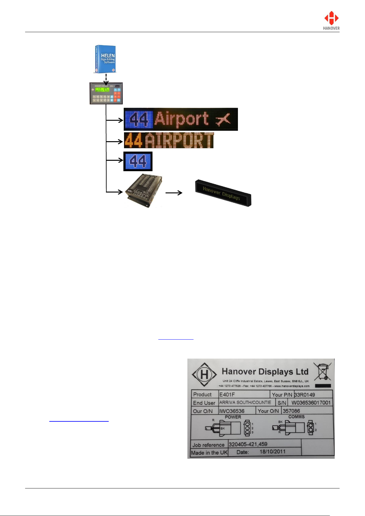
ERIC++ Controller – Installation and Operation Manual
Destination sign (front)
Destination sign(s) (side)
Destination sign (rear)
ERIC++ controller
On-board computer
Internal LED sign(s)
Figure 2 - a communications network which includes an on-board computer
A database of information for all signs within a system is created on a standard Windows PC, using Helen
software. The database is then uploaded to the controller. Each sign has a processor with an address
switch that is associated with the configuration for that sign set within Helen. This allows it to receive the
appropriate information via the ERIC++ which is connected to the sign by a multi-drop communications
network.
Note that any ERIC++ configuration parameters set in Helen that are loaded into the controller will be
overwritten by any manual changes to those parameters made later directly via the controller itself.
Further list downloads may overwrite such manual changes.
Note also that any manual alterations that conflict directly with Helen-programmed parameters should be
avoided as the results are unpredictable.
Full technical details are provided in section 3 Operation.
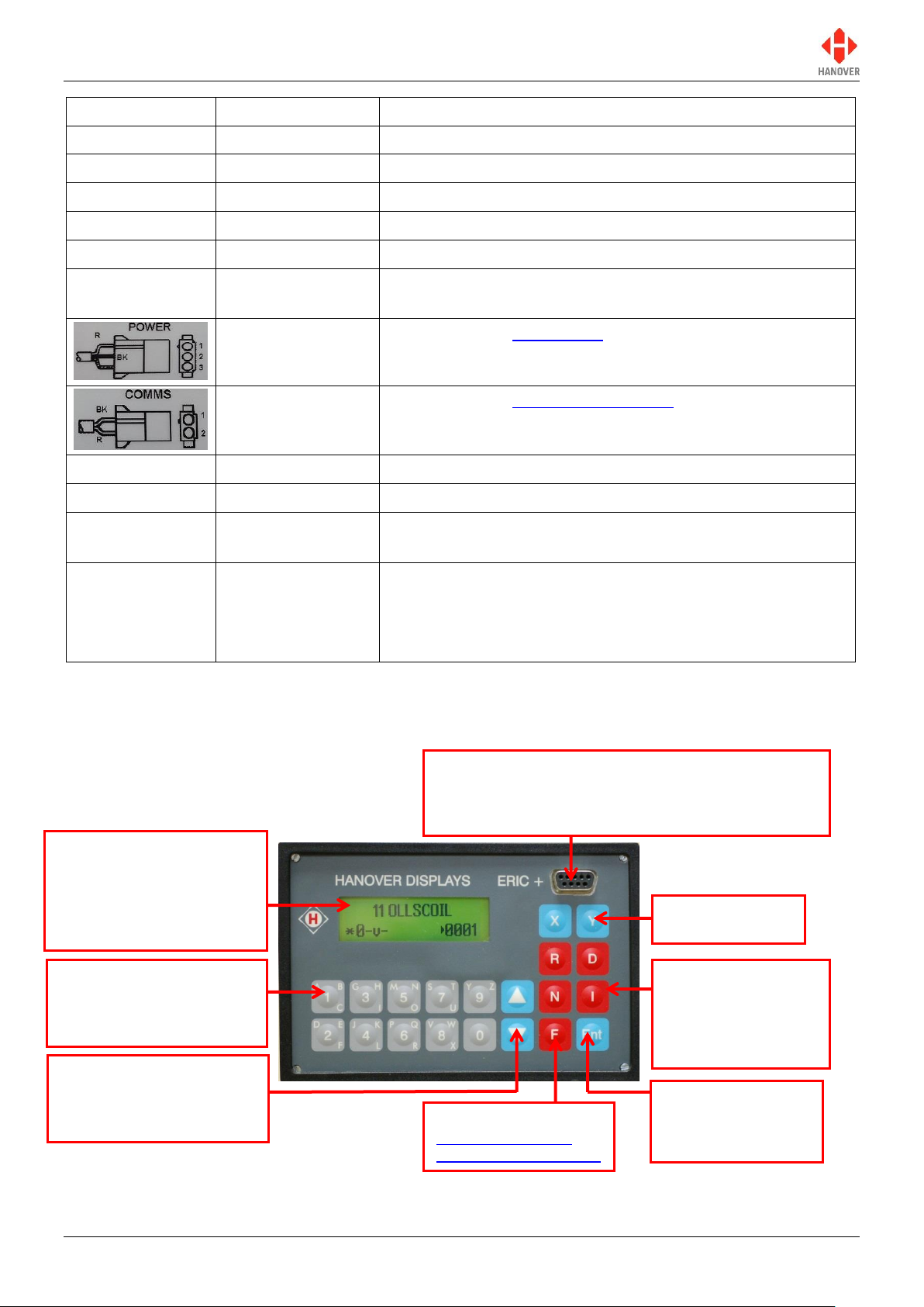
1.5 Identification
The controller's identification can be determined from
the silver label on the casing.
In addition to identifying the model, it may be
necessary to determine the software version
installed, especially for technical support queries. To
ascertain the version in use, go to 'Show status' in
section 3.5.1 Status options.
540114-8 page 9 of 59 17/03/2015
Figure 3 – silver label on casing of controller
ERIC++ Controller – Installation and Operation Manual
Features
Meaning
Description
Product
-
Identifies the specific model.
Your P/N
Your Part Number
Specific to each controller.
End User
-
Is generally the ultimate operator of the vehicle.
S/N
Serial Number
Specific to each controller.
Our O/N
Our Order Number
Number used for internal use by Hanover.
Your O/N
Your Order
Number
Number used to identify the order for this controller.
Power connector
Refer to section 2.2.1 Power.
Comms connector
Refer to section 2.2.2 Communication.
Job reference
-
For the use of builder or end user.
Made in the UK
-
Shows the country of manufacture of the controller.
Date:
Date when the finished controller is available for shipment
after all checks, tests and approvals are complete.
Exx-10R-yyyyyy
European standard
E number
xx = country code.
10R = current version of standard.
yyyyyy = approval number applicable to this family of
products.
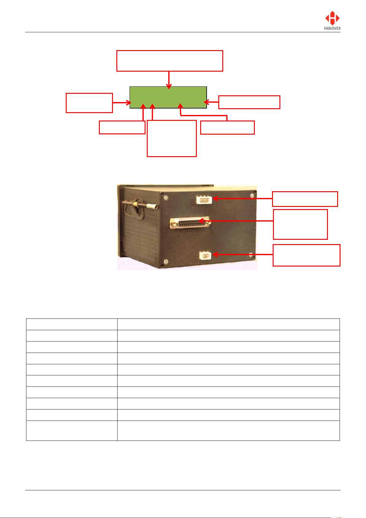
Front panel connector (9-way D type): for transferring
destinations lists/updating firmware from a Keylo data
loader or when using ERIC++ as a data loader via a
serial cable
LCD display: provides
visual information to the
driver or user about the
currently selected
destination and operating
status of the ERIC++
Alphanumeric keys: for
entering route, destination,
information and lock codes
X & Y: round trip
(aller-retour)
F: Function
3.5 Accessing other
functions of the ERIC++
R: Route
D: Destination
N: Advertising or next
stop messages
I: Information
Up and down arrow keys:
for incrementing or
decrementing destination,
route or values
Ent: Enter
For confirming
selection or entry of
data
1.6 Controller overview
1.6.1 Front view
540114-8 page 10 of 59 17/03/2015
Figure 4 - front side of the controller
ERIC++ Controller – Installation and Operation Manual
Lewes
-- -- * ---- ----
Specification
Values / Description
Case dimensions
W144mm x H96mm x D120mm
Mounting
Dashboard / panel, using mounting housing bracket
Cut out required
W138mm x H92mm x D150mm
Screen dimensions
59.5mm x 17.5mm
Screen display
LCD with two lines of text maximum
Weight
0.9kg
Operating voltage
18-32Vdc
Normal operating power
0.5A @ 24Vdc
Operating temperature
range
-20°C to +60°C
Content of front sign or driver
message for current destination
Destination code
Route code
Information
code
Advert code
* displayed if
there is one
or more sign
errors
Power connector
Communication
connector (RS485)
25-way D-type
multicomms
connector
1.6.1.1 Example of LCD display
Figure 5 – Example of LCD display of the controller
1.6.2 Rear view
1.7 Technical information
1.7.1 Specification
Figure 6 - rear side of the controller
540114-8 page 11 of 59 17/03/2015

ERIC++ Controller – Installation and Operation Manual
1.7.2 System supply voltages
All Hanover 24V devices are suitable for the full voltage supply range found on vehicles with a 24V battery.
For supply voltage details, please refer to the technical information for a specific product.
540114-8 page 12 of 59 17/03/2015

ERIC++ Controller – Installation and Operation Manual
Position
Advantages
Disadvantages
Above or below the
driver’s window or above
the windscreen in the
sign pod
This area usually has sufficient space
to accommodate the controller and the
cabling. It also allows easy access for
maintenance.
Awkward for drivers to operate
and difficult for them to view.
Left or right on the dash
Good visibility and access. Wiring and
servicing is normally straightforward.
Difficult to find sufficient depth of
space on modern vehicles.
Below the pod above the
driver’s head
Good visibility and access. Wiring and
servicing is normally straightforward.
Possible water damage if window
is opened.
Warning: Drivers should never attempt to operate the controller whilst driving.
The controller is not waterproof. Do not position the unit where it is likely to come into contact
with water / moisture – for example, under an opening window.
Water ingress is not covered by the product warranty.
Cables and connectors used must be appropriately rated for the particular vehicle
installation. Cable insulation should be selected in accordance with the application
requirements for heat, fire and smoke resistance.
Installation
2.
2.1 Standard positions for the controller are:
on the dash, to the right or left-hand side
in the sign pod
above or below the driver’s window.
Care must be taken to ensure enough space is provided at the rear of the controller unit for the power and
communication cables.
It is important to mount the controller in a suitable position for the driver for best access and visibility.
2.2 System wiring
Cable assemblies can either be made by the user to their own requirements or ordered from Hanover.
2.2.1 Power
It is recommended that the ERIC++ is wired to a master switch or isolator switch.
The pins of the 3-pin power connector are:
Pin 1 = +24V
Pin 2 = 0V
Pin 3 = +24V optional output
540114-8 page 13 of 59 17/03/2015

ERIC++ Controller – Installation and Operation Manual
2.2.2 Communication
The pins of the 2-pin communication connector are:
Pin 1 = comms- (black)
Pin 2 = comms+ (red)
Note: The pins of the 2-pin sign communication connector are reversed in the case of a DERIC+ controller.
2.2.3 Multicomms
Wiring for bus reversing and battery guard is via the 25-way D-type drawing no. 0003/05/118. For more
information, refer to Appendix A: Cable Assembly Drawing.
540114-8 page 14 of 59 17/03/2015
ERIC++ Controller – Installation and Operation Manual
No.
Description
Figure
1
The green backlight becomes lit and the following start up screens
will be displayed.
Note: Some of the initial screen displays may appear very quickly.
2
If everything is correct, it will change to the driver's information
screen (NO DATA if no database has been transferred to the
controller or Idle if the controller already contains a database or last
destination code if programmed using configuration code RS (refer
to Appendix E: Configuration Code Options)) where the software
version is displayed. However, if an error occurs during software
initialisation, the screen may freeze while showing one of the codes.
If so, the user should restart the process. If this does not work, the
code should be noted and Hanover informed because it will help
establish the cause of the problem.
abcd**...e
ERIC-H8S-1-23
Ext Port 2345
NCPO12345//
NO DATA
-- ----
Idle
-- -- * ---- ----
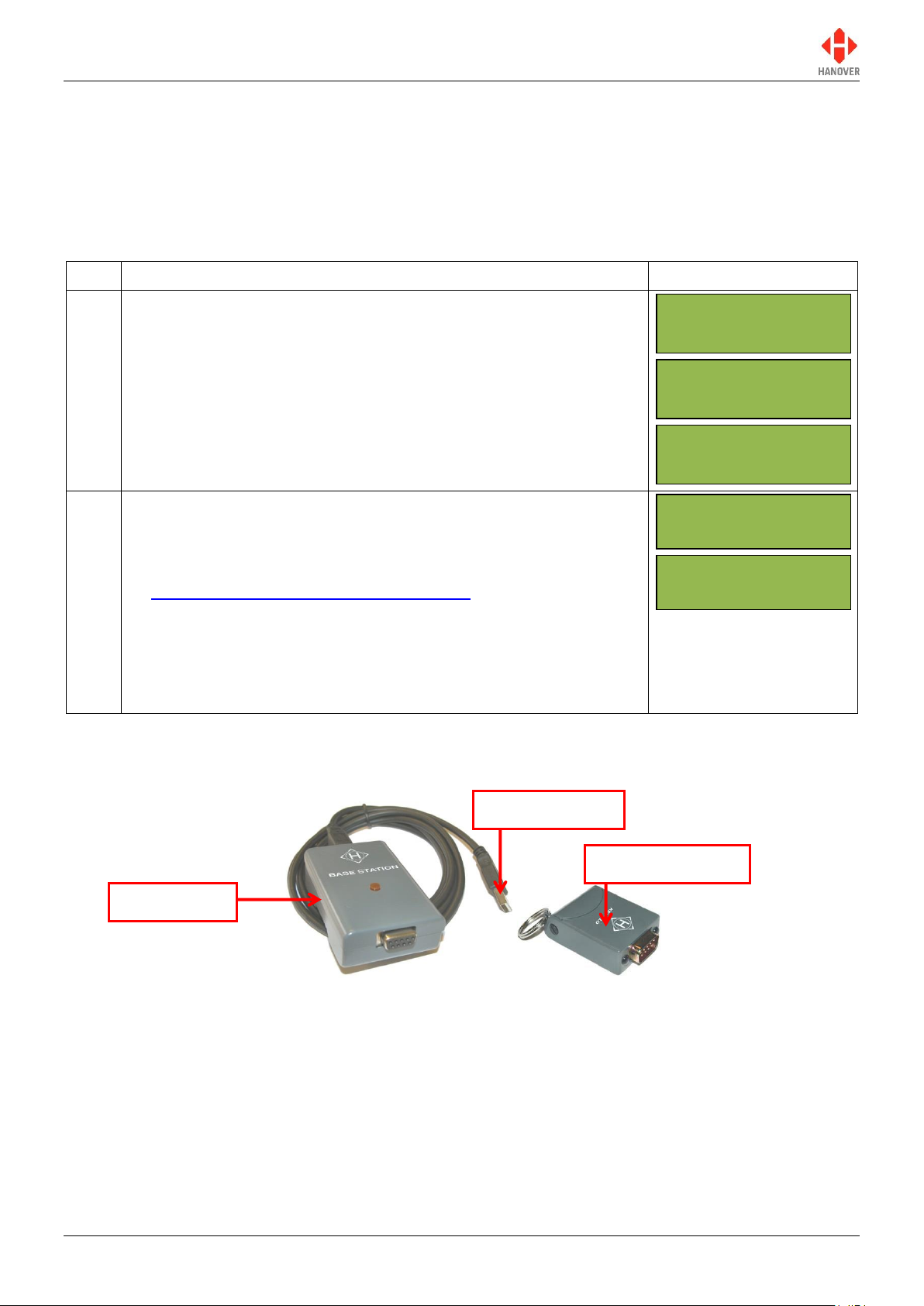
USB plug to PC
Base station
Keylo data loader
Operation
3.
3.1 Getting started
3.1.1 Boot screens on power-up
Whenever the ERIC++ is powered up or restarted, it carries out a series of initialising checks. Normally,
this sequence is rapid and can be ignored.
3.2 Loading a database into the ERIC++ from Helen
3.2.1 Base station and Keylo data loader
Figure 7 – base station and Keylo data loader
The most convenient device is the Keylo, a small, robust key fob device that fits easily in the pocket which
can be loaded from a PC via Helen software with an available USB port, taken to the vehicle and plugged
into the ERIC++ front panel connector where loading will start automatically.
To load the database to the Keylo dataloader using Helen, please ensure the Keylo’s base station is
connected to the PC. For further details about the Keylo, please refer to “Keylo Operating Manual – ref.
0020/54/0039/F”.
540114-8 page 15 of 59 17/03/2015
3.2.2 Transferring the database to the Keylo dataloader using Helen
ERIC++ Controller – Installation and Operation Manual
Step
Description
Figure
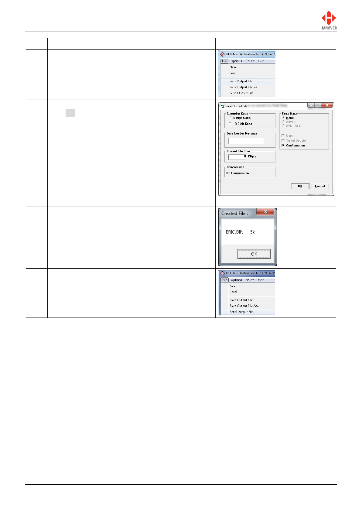
1
In the main Helen window, click File Save Output
File as shown.
2
Verify that the options selected are correct and then
click OK.
For more details, refer to Helen display-editing
software operating manual (ref. 540125-10).
3
The ERIC.BIN file will be created as shown.
4
In the main Helen window, click File Send Output
File as shown.
540114-8 page 16 of 59 17/03/2015
ERIC++ Controller – Installation and Operation Manual
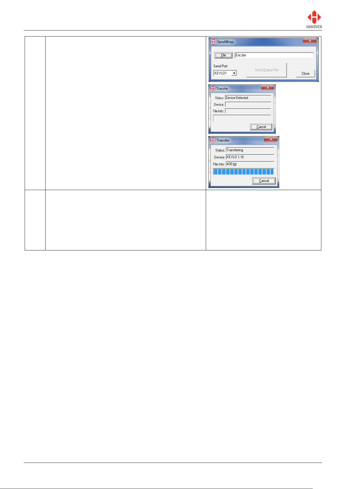
5
When the ‘SendWrap’ dialogue box appears, plug the
Keylo into the base station and data transfer will start
automatically.
Note: Please make sure ‘KEYLO1’ is set in Send Port.
6
When loading is finished, ‘Transfer complete’ will be
displayed briefly in the Status section of the Transfer
dialogue box. The LED on the Keylo will turn solid
green. The Keylo can now be removed.
Note: If the LED light on the Keylo is not solid green, try
loading the list again by removing the Keylo from the
base station and restarting the load process.
540114-8 page 17 of 59 17/03/2015
ERIC++ Controller – Installation and Operation Manual
Step
Description
Figure
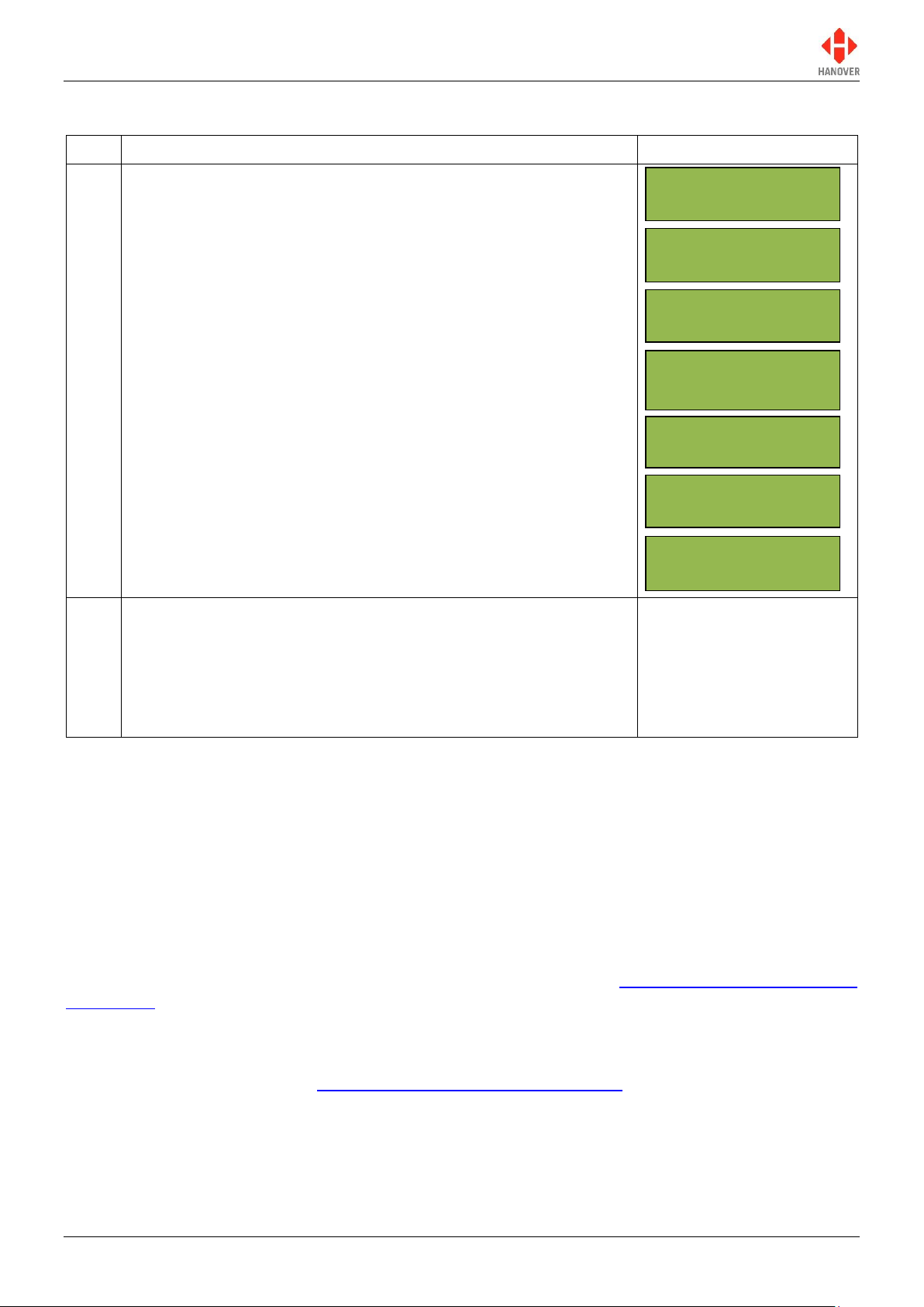
1
Insert the Keylo into the D9-socket on the front of the controller:
again, data transfer will start automatically. Once the list has been
loaded, the controller will display ‘Busy’. The LED light should
again be solid green: it can then be removed and the controller will
finish decompressing the list until finished.
2
After the process has finished, select one of the new destination
codes to verify that the list has been loaded correctly. To do so,
press the D key and enter a destination code using the
alphanumeric key.
The Keylo can now be used to transfer the list to as many vehicles
as required.
Polling...
Waiting...
Loading...
ERIC-H8S-1-23
Ext Port 2345
Busy...
NC01234501234//
Idle
-- -- * ---- ----
3.2.3 Transferring the database from the Keylo to the ERIC++
3.3 Selecting the information to be shown on the signs
The controller uses the database (including the destination list) loaded from Helen to populate the vehicle's
signs. Route/destination information and/or adverts and other information can be stored in the database.
The ERIC++ manages this information by accessing a range of codes. Pressing the F, D, R, N or I keys
when the controller is in the driver’s operational mode will cause the controller to display the corresponding
code (in condition they are set to enable in the configuration status of the controller).
In normal operational mode, the default position of the ERIC++ is to show the current route / destination
code (in driver's operational mode): the controller will revert to this state after 20 seconds of inactivity,
regardless of what has been showing on its screen. Although rarely needed by the vehicle driver, the lock
code is also included in this cycle. For more details, please refer to section 3.5 Accessing other functions of
the ERIC++.
3.3.1 Destination code
The destination code is accessible using the D key on the front panel of the controller (if the configuration
code DN is set to enable (refer to Appendix E: Configuration Code Options)). It determines the information
shown on the destination and in-bus signs and is used in a standard configuration. The information is
usually in the form of a place name and/or route number whilst the code itself is a four to ten-digit number.
540114-8 page 18 of 59 17/03/2015
 Loading...