

Page 1
HanoverOutdoorFurniture
IMPORTANT
Ifyouhaveanyproblemswiththisproduct(missingordamagedparts,assemblyissues,etc.),
PLEASEDONOTRETURNTOTHERETAILER/STORE
fromwhereyoupurchasedtheproduct.
PleasecallourToll‐FreeCustomerServiceHotlineat:
Between9:00AMand5:00PMEasternTime,MondaythroughFriday
Orvisitourwebsiteat:
Toexpediteanyfuturewarrantyclaims,pleaseretaintheInstructionSheet,Warranty
Cardandreceiptforfutureuse.
For additionalon‐linesupportonassembly,troubleshootingandcare&maintenanceofyouroutdoor
furniture,pleasevisitourwebsiteat:www.hanover‐products.com.
www.hanover‐products.com
1‐800‐416‐3511
6/1/2015(a)
Page 2
ASSEMBLY INSTRUCTIONS
1
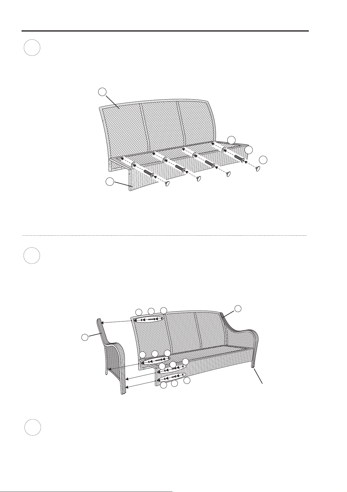
Attach the seat frame to the back frame by using four 5/16"x40 mm bolts and washer as shown in
Guide these bolts through the holes in the seat frame, into the fixed nuts already in place in the back frame.
.Do not over tighten
Figure 1.
A
G
F
H
B
2
Attach love seat arm by inserting two mm bolts with washers through the holes in front seat portion
of the love seat frame and into the holes in the love seat arm shown in . Attach back of love seat arm
by inserting two mm bolts with washers through holes in the back portion of love seat frame and into
the holes in the rear portion of the love seat arm as shown in . . Repeat for the
opposite side.
5/16"x40
D
5/16"x25
G
G
Figure 2
Figure 2 Hand tighten only
H
F
H
F
H
E
G
H
E
G
C
FOOT CAP-1
3
Tighten all bolts using the hex bolt driver provided. Tighten each bolt a few revolutions at a time, alternating
between bolt connections until all bolts are tight.
damage the welds or frame.
Cover all bolts with bolt covers provided.
Do not over tighten. Over tightening may strip bolts or
Page 3
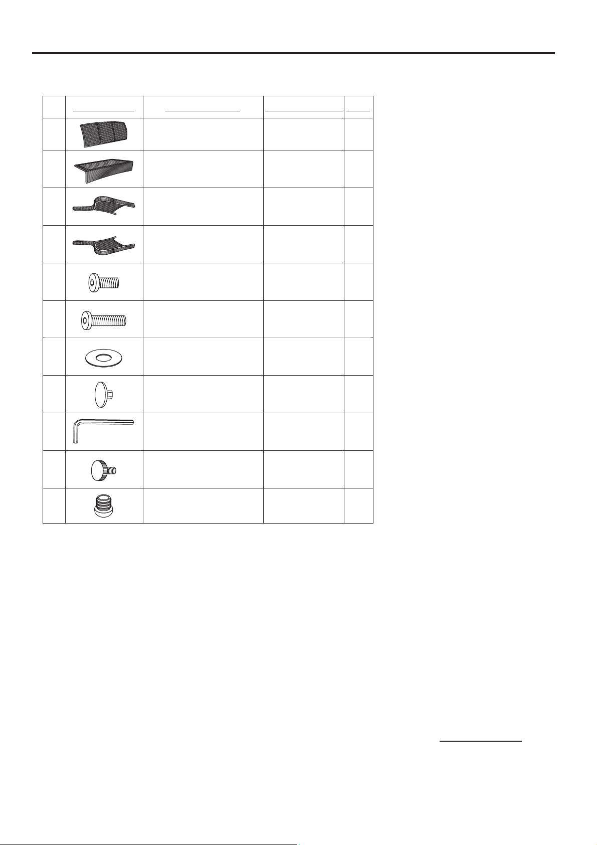
PARTS IDENTIFICATION LIST
*NOTE:PARTSSHOWNONPARTSLISTARENOTTOSCALE
PARTS LIST DESCRIPTION ORDER PART #
A
B
C
D
E
F
G
H
BACK FRAME
SEAT FRAME
LEFT ARM
RIGHT ARM
5/16" X 25 MM BOLT
5/16" X 40 MM BOLT
Ø8.5 X 1.5 MM
WASHER
BOLT COVER
SK0939
SK0940
SK0941
SK0942
HW0186
HW0275
HW0005
HW0022
QTY
1
1
1
1
4
8
12
12
I
HEX BOLT DRIVER
FOOT CAP-1
FACTORY ASSEMBLY
FOOT CAP-2
FACTORY ASSEMBLY
HW0006
FC0030
FC0308
1
BGC08006
Page 4
ASSEMBLY INSTRUCTIONS
1
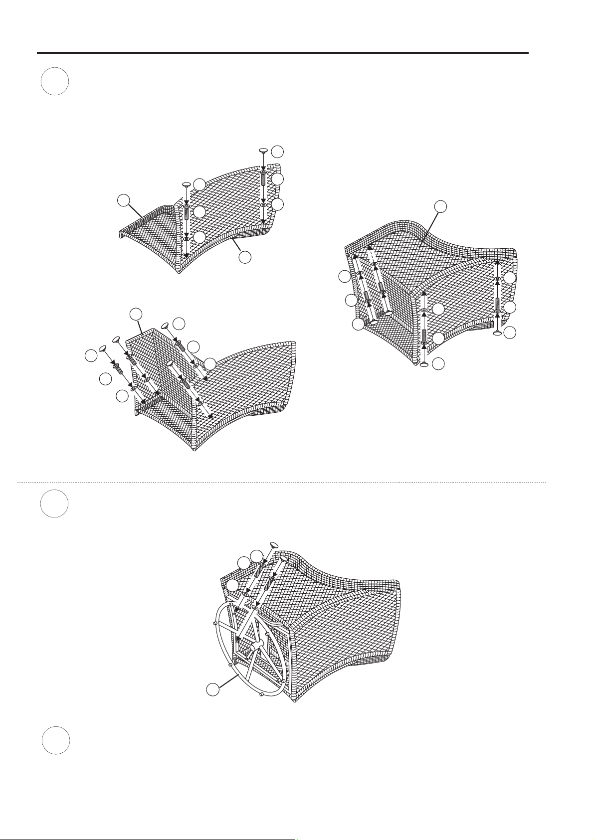
Assemble furniture on a smooth, non-abrasive surface. by using two
5/16"x40 mm bolts and washers as shown in . Guide the bolts through holes in back frame, into
pre-drilled holes in the . and back frame
by using four 5/16"x25 mm bolts and washers as shown in . A
to back
shown in .
and seat frame by using two 5/16"x25 mm bolts and two 5/16"x40 mm bolts and four washers as
Fig.3 Hand tighten only.
D
right arm Attach the seat frame to right arm
I
G
H
Hand tighten only.
B
Fig.1
I
G
H
Fig.1
A
I
F
I
F
H
Attach the back frame to right arm
Fig.2 Hand tighten only.
H
F
I
ttach the left arm
C
H
G
I
H
G
I
2
H
Fig.3
Fig.2
Attach the complete base to the complete seat by using four 5/16"x40 mm bolts and washers as shown
in . Guide the bolts through holes in base, into the pre-drilled holes in the seat.Fig.4 Hand tighten only.
I
G
H
3
E
Fig.4
Using the hex bolt driver provided, tighten all bolts.
too tight or too loose, the glider will not function properly.
motion should be smooth.Adjust tension on the glider brackets, nuts and bolts as needed. Cover nuts
and bolts with covers provided.
Do not over tighten bolts. If nuts and bolts are
Test the operation of glider. Gliding
Page 4
Page 5
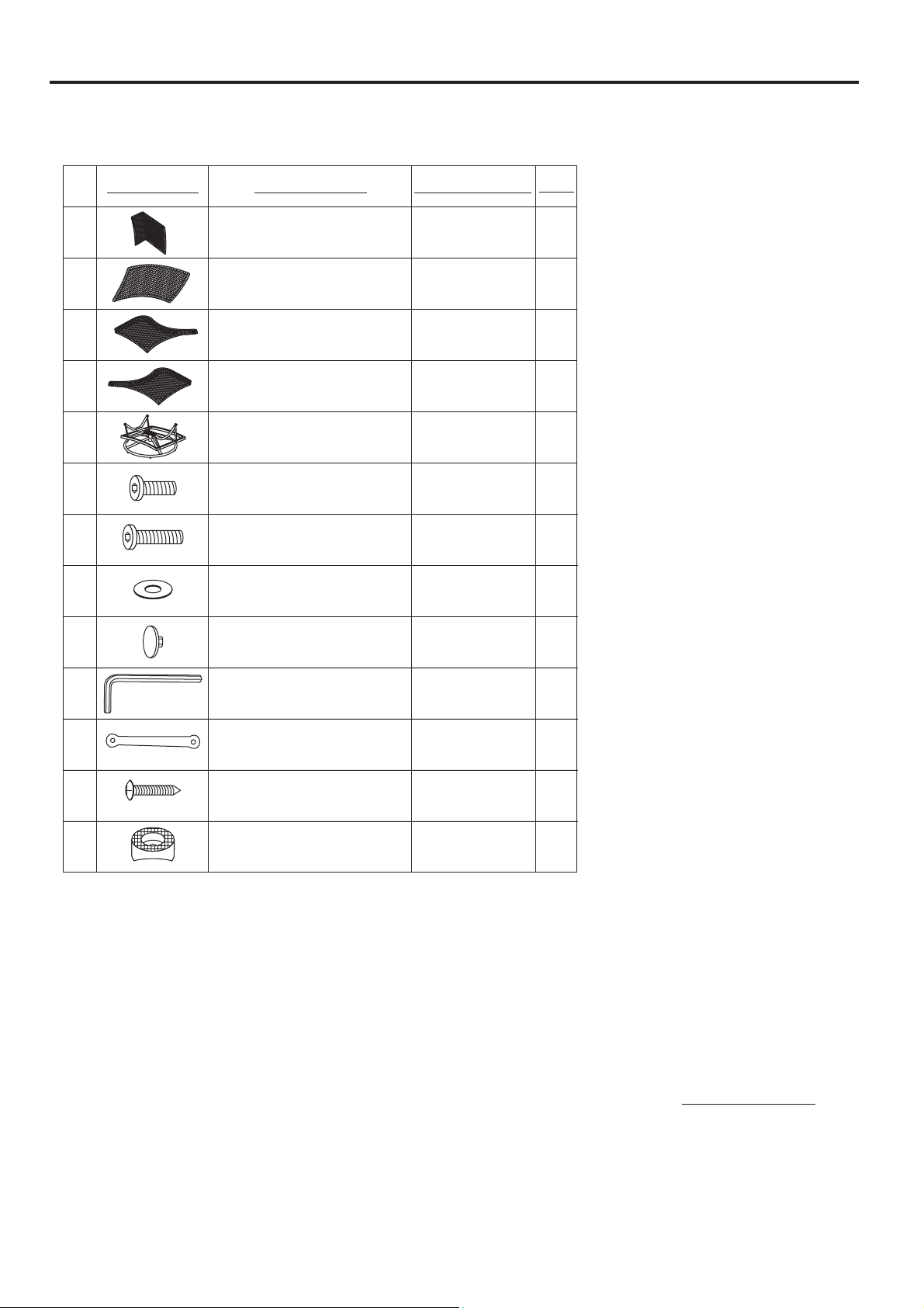
PARTS IDENTIFICATION LIST
*NOTE:PARTSSHOWNONPARTSLISTARENOTTOSCALE
PARTS LIST
A
B
C
D
E
F
G
H
DESCRIPTION ORDER PART #
SEAT FRAME
BACK FRAME
LEFT ARM
RIGHT ARM
GLIDER BASE W/
GLIDER BRACKET
5/16" X 25 MM BOLT
5/16" X 40 MM BOLT
SG0154
SG0155
SG0156
SG0157
SG0158
SG0159
HW0186
HW0275
HW0005Ø8.5 X 1.5 MM WASHER
QTY
1
1
1
1
1
1
6
8
14
I
J
BOLT COVER
HEX BOLT DRIVER
GLIDER BRACKET
FACTORY ASSEMBLY
ST4 8 X 25 BOLT.
FACTORY ASSEMBLY
FOOT CAP
FACTORY ASSEMBLY
HW0105
HW0006
G0080
HW0695
FC0013
14
1
Page 5
BGS12023
Page 6
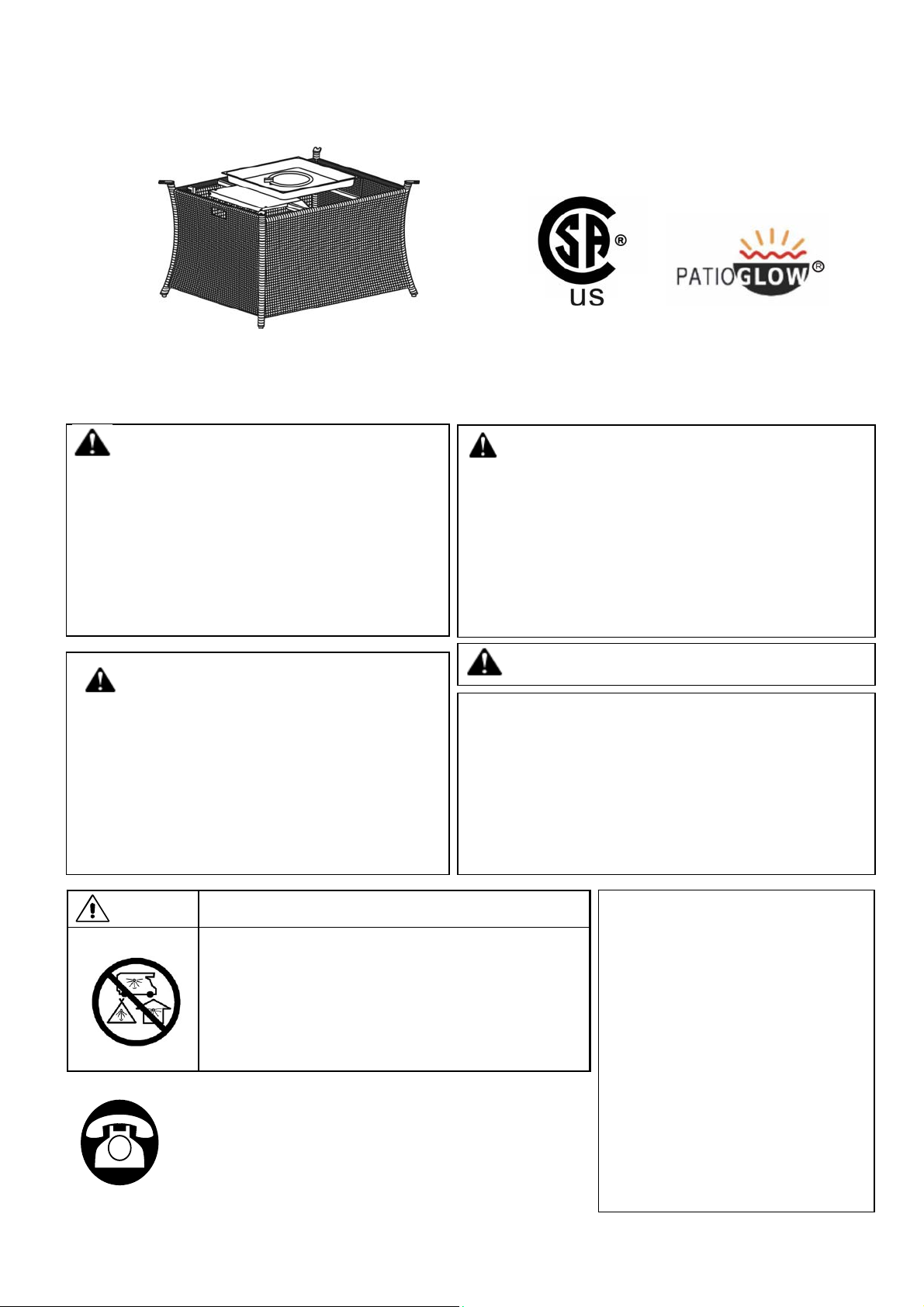
ASSEMBLY INSTRUCTIONS
Thi
A
Installer: Leave these instructions with consumer.
Consumer: Keep these instructions for future reference.
DANGER
If you smell gas:
1. Shut off gas to the appliance.
2. Extinguish any open flame.
3. If odor continues, keep away from
WARNING
Do not store or use gasoline or other
flammable vapors and liquids in the
vicinity of this or any other appliance.
An LP-cylinder not connected for use
shall not be stored in the vicinity of this
or any other appliance.
the appliance and immediately call
your gas supplier or fire department.
WARNING:
Improper installation, adjustment alteration,
service or maintenance can cause injury or
property damage. Read the installation,
operating and maintenance instructions
thoroughly before installing or servicing this
equipment.
WARNING: For Outdoor Use Only
FOR USE WITH 20LB (9KG) PROPANE
CYLINDER WITH TYPE 1 CONNECTION OR FOR
USE WITH NATURAL GAS AFTER C ONVERSION
KIT IS INSTALLED (MUST BE PROFESSIONALLY
INSTALLED).
CSA Model 98910
RL11103
DANGER CARBON MONOXIDE HAZARD
s appliance can produce carbon
monoxide which has no odor.
Using it in an enclosed space can kill
you.
Never use this appliance in an enclosed
space such as a camper, tent, car or
home.
Questions, Problems, Missing Parts? Before returning to
your retailer, call our customer service department in the
US and Canada at 1-800-416-3511, Monday-Friday, 9 a.m.
– 5 p.m. Eastern Time.
Sep-01-2015
WARNING:
USE FACTORY APPROVED
REPLACEMENT PARTS AND
ACCESSORIES ONLY. USE
OF UNAPPROVED PART OR
ACCESSORIES CAN VOID
THE WARRANTY ON THIS
PRODUCT AND RESULT IN A
HAZARDOUS CONDITION.
PLEASE CONTACT US FOR
INFORMATION REGARDING
REPLACEMNT HOSES,
THERMOCOUPLES,
ELECTRODES, IGNITION
MODULES, LAVAROCKS,
LOGS, FIRE ICE, ETC.
Page 7

IMPORTANT SAFETY INFORMATION
The installation must conform with local codes
Fuel Gas Code, ANSI Z223.1/NFPA 54; International Fuel Gas Code. ; Natural Gas and Propane
Installation Code, CSA B149.1; or Propane Storage and Handling Code, B149.2, as applicable.
The appliance and its appliance main gas valve must be disconnected from the gas supply piping
system during any pressure testing of that system at test pressures in excess of 1/2 psi (3.5kPa).
The appliance must be isolated from the gas supply piping system by closing its equipment shutoff
valve during any pressure testing of the gas supply system at test pressure equal to or less than
1/2 psi (3.5kPa).
The appliance area must be kept clear and free from combustible materials, gasoline and other
flammable vapors and liquids.
Do not use this appliance if any part has been under water. Immediately call a qualified servic e
technician to inspect the appliance and to replace any part of the control system and any gas
control which has been under water.
Children and adults should be alerted to the hazards of high surface temperatures and kept
at a safe distance to avoid burns or clothing ignition.
Young children should be carefully supervised when they are anywhere near the appliance.
Clothing or other flammable material should not be hung from the appliance, or placed on
or near the appliance.
or, in the absence of local codes, with the National
Any screen or guard removed for servicing an appliance must be replaced prior to
operating the appliance.
Installation and repair should be done by a qualified service person. The appliance should
be inspected before use and at least annually by a professional service person. More
frequent cleaning may be required as necessary. It is imperative that the control
compartments, burners and circulating air passageways of the appliance be kept clean.
Do NOT burn solid fuels in this gas fireplace.
Do NOT ignite the burner before pouring all of the burner media (lava rock or fire glass) into the
burner pan. The media must be evenly distributed over the burner.
CAUTION: The propane gas pressure regulator provided with this appliance must be used. This
regulator is set for an outlet pressure of 11 inches water column.
This outdoor gas appliance is not intended to be installed in or on recreational vehicles and/or
boats.
Before each use of this gas appliance, open the LP (Liquid Propane) Tank Drawer and inspect the
LP Hose. If there is evidence of excessive abrasion or wear, or the hose is cut, it must be replaced
prior to the gas appliance being put into operation. Use only the replacement hose assembly
specified in this manual. Inspect the burner before each use of the appliance. The burner must be
replaced prior to the appliance being put into operation if it is evident that the burner is damaged.
Use only the burner listed in these instructions.
Keep the fuel supply hose away from any heated surfaces.
Page 8
IMPORTANT SAFETY INFORMATION
ABOUT PROPANE (LP) GAS
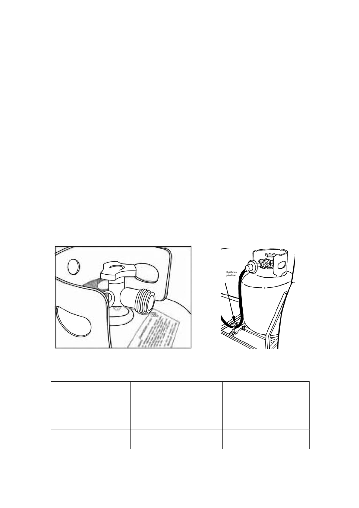
A self contained LP-gas cylinder for use with this appliance must have a
capacity of 20 lbs. and must be equipped with a Type 1 connector and an OPD
(overfill protection device). See Figure 1.
The LP-gas supply cylinder to be used must be constructed and marked in
accordance with the specification for LP-gas cylinders of the U.S. Department
of Transportation (DOT) or the National Standard of Canada, CAN/CSA-B339,
Cylinder, Sphere and Tubes for the Transportation of Dangerous Goods.
The cylinder supply system must be arranged for vapor withdrawal.
The cylinder used must include a collar to protect the cylinder valve.
This appliance shall be used only outdoors in a well-ventilated space and
shall not be used in a building, garage or any other enclosed space.
When this appliance is not is use, the gas must be turned off at the supply
cylinder.
Storage of this appliance indoors is permissible only if the cylinder is
disconnected and removed from the appliance.
Cylinders must be stored outdoors in a well-ventilated area out of the
reach of children .Disconnected cylinders must have threaded valve plugs
tightly installed and must not be stored in a building, garage or any other
enclosed areas.
CSA (Canadian Standards Association) certified to ANSI Z21.97•CSA
2.41-2015 “ Outdoor Decorative Gas Appliances” The gas hose is routed
through a “U” bolt to prevent the hose from coming in contact with the burner.
DO NOT remove the hose from the “U” bolt. See Figure 2.
Regulator hose
pointed down
Figure 1 Figure 2
SPECIFICATIONS
INPUT 40,000 Btu/hr 30,000 Btu/hr Low fire
Propane Regulator
Pressure
Natural Gas Minimum
Inlet Pressure
Clearances to
combustible surfaces
11 inches water column
7 inches water column
Sides 24in./61cm Top: 72 in. / 183 cm
Page 9
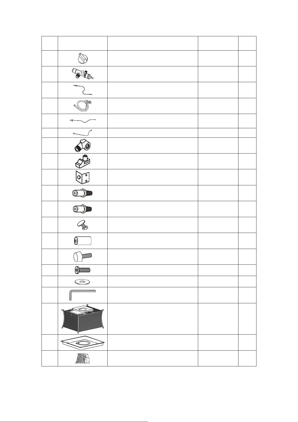
PARTS IDENTIFICATION LIST
PART
A CONTROL KNOB FP0245 1
B GAS VALVE FP0307 1
C THERMOCOUPLE FP0004 1
D LP REGULATOR HOSE FP1369 1
E
F GAS TUBE FP0309 1
G ORIFICE ELBOW FP1385 1
H IGNITION MODULE FP0006 1
I ORIFICE BRACKET FP0311 1
DESCRIPTION PART# QTY
ELECTRODE FP1375 1
J PROPANE ORIFICE FP1283 1
K NATURAL GAS ORIFICE FP1284 1
L LP TANK RETAINING KNOB FP0585 2
M “AAA” BATTERY(1.5V) HW0705 1
N
O BOLTS HW0036 4
P WASHERS HW0103 4
Q HEX BOLT DRIVER HW0006 1
R FIREPIT BASE FP1532 1
ADJUSTABLE FOOT CAPS FC0553 4
T
V FIRE ICE SET ZCF0092 1
FIREPAN/BURNER
ASSEMBLY
FP1533 1
Page 10
INSTALLATION
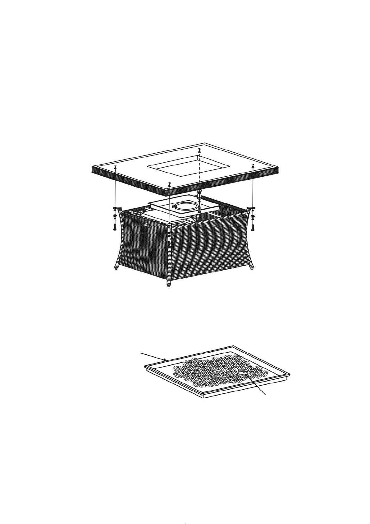
1. With the help of another person, turn the table base assembly in the
upright position. Carefully place the table top (not included) onto the table
base. After making any necessary adjustments to the alignment of the
table top and firepit base, use bolts and washers as shown in Figure 3.
Guide the bolts through the holes in the base brackets, into the pre-drilled
holes in the table top. Do not tighten completely. Repeat on other three
sides. (Note: holes do not go through to the top of the table. Holes shown
for illustration purposes only.)
Figure 3
2. Pour all of the fire ices into the burner pan. Completely cover the burner
tube with fire ices as shown in Figure 4.
Burner Pan
Figure 4
Ignition Well
Page 11
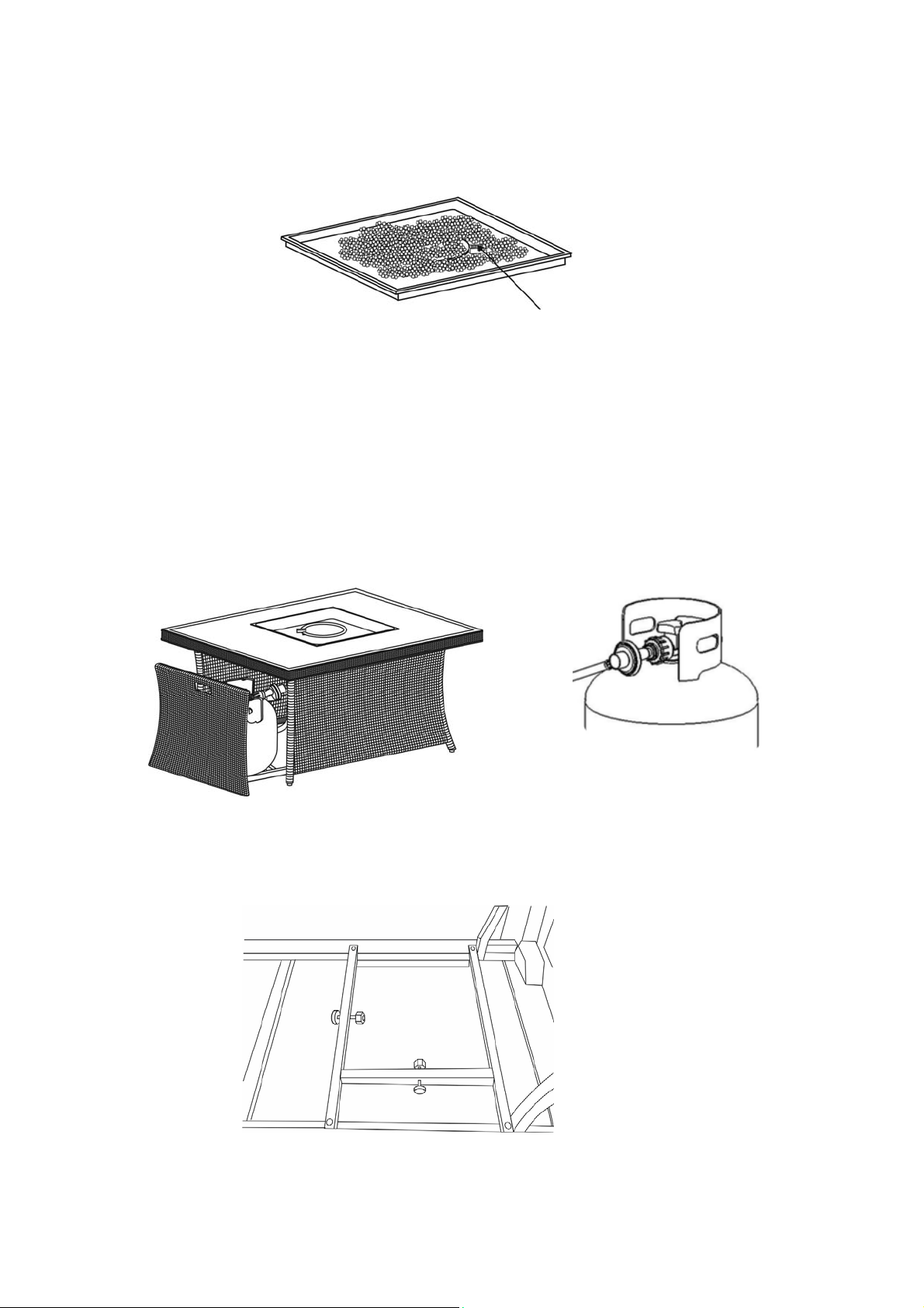
3. Remove the cardboard cover from the ignition well as shown in Figure 5.
Remove any lava rock or fire ice on top of ignition well.
Figure 5
Cardboard Cover
4. Lift off the tank door, place the tank in the holder and use the chain to hold
the tank. Connect the regulator as shown in Figure 6. Turn the black handle
clock-wise to tighten. Turn the handle counterclock-wise to remove. The
hose must point down. Open the control door and check that the valve is
turned all the way clockwise to the “OFF” position. Open the tank valve.
Apply a solution of soapy water to the tank-regulator connection and to the
valve-hose connection to check for leaks. If soap bubbles continue to form,
the connection has a leak. If a leak is found, close the tank valve and
tighten all connections. NEVER USE A FLAME TO CHECK FOR
LEAKS.
Figure 6
5. Tighten threaded knobs found on tank tray (Figure 7) so that the LP tank
cannot move from side to side. Do not remove plastic cap from end of
threaded section.
Figure 7
Page 12
NATURAL GAS CONVERSION
Natural gas conversion must be performed only by your natural gas provider or
service company.
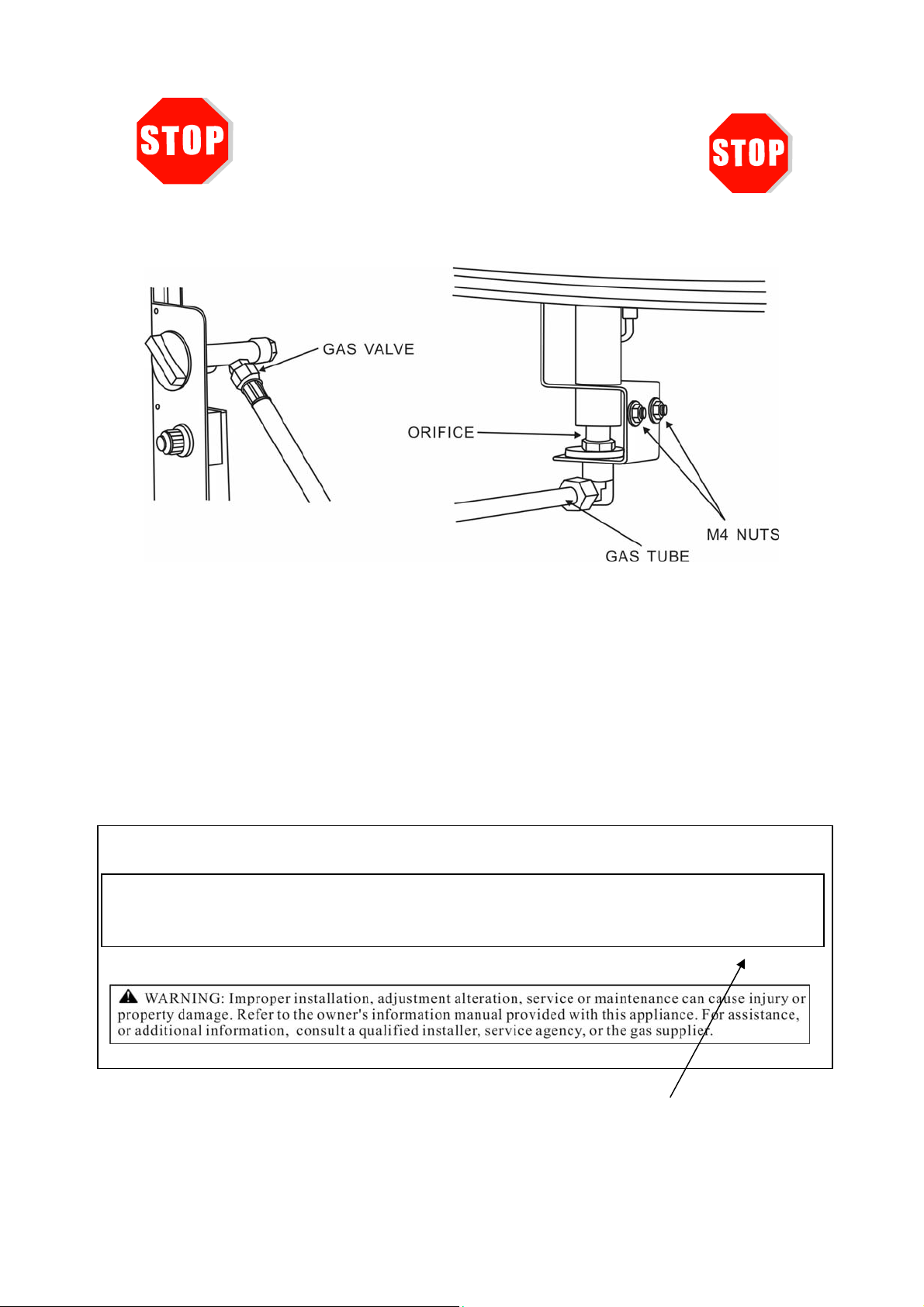
1.Disconnect the regulator hose from the gas valve. See Figure 8.
Figure 8
2.Disconnect the gas tube from the orifice elbow. Remove the two M4 nuts and remove
the orifice holder. Replace the propane orifice with the natural gas orifice from the kit and
reinstall the orifice holder. Apply a solution of soapy water to all connections to check for
leaks. If soap bubbles continue to form, the connection has a leak. If a leak is found, close
the main valve and tighten all connections.
LEAKS.
NEVER USE A FLAME TO CHECK FOR
3.Stick
the conversion label on the rating plate as shown in Figure 9.
Metal Rating Plate
Serial Number _________________ Model Number: 98910
CAUTION: The gas pressure regulator provided with this appliance must be used. This regulator is set for an outlet pressure of
This appliance has been converted to use Natural Gas. Input 40,000 Btu/hr.
Max Gas Supply Pressure 7 inch w.c. (1.74 kPa) Min. Gas Supply Pressure 5 inch w.c. (1.24 kPa)
Minimum clearance from combustible constructions: Sides: 24 in.609 mm. Top 72 in. 1828 mm.
FOR OUTDOOR USE ONLY. If
stored indoors, detach and leave cylinder outdoors.
Figure 9 Conversion Label
Page 13
LIGHTING INSTRUCTIONS
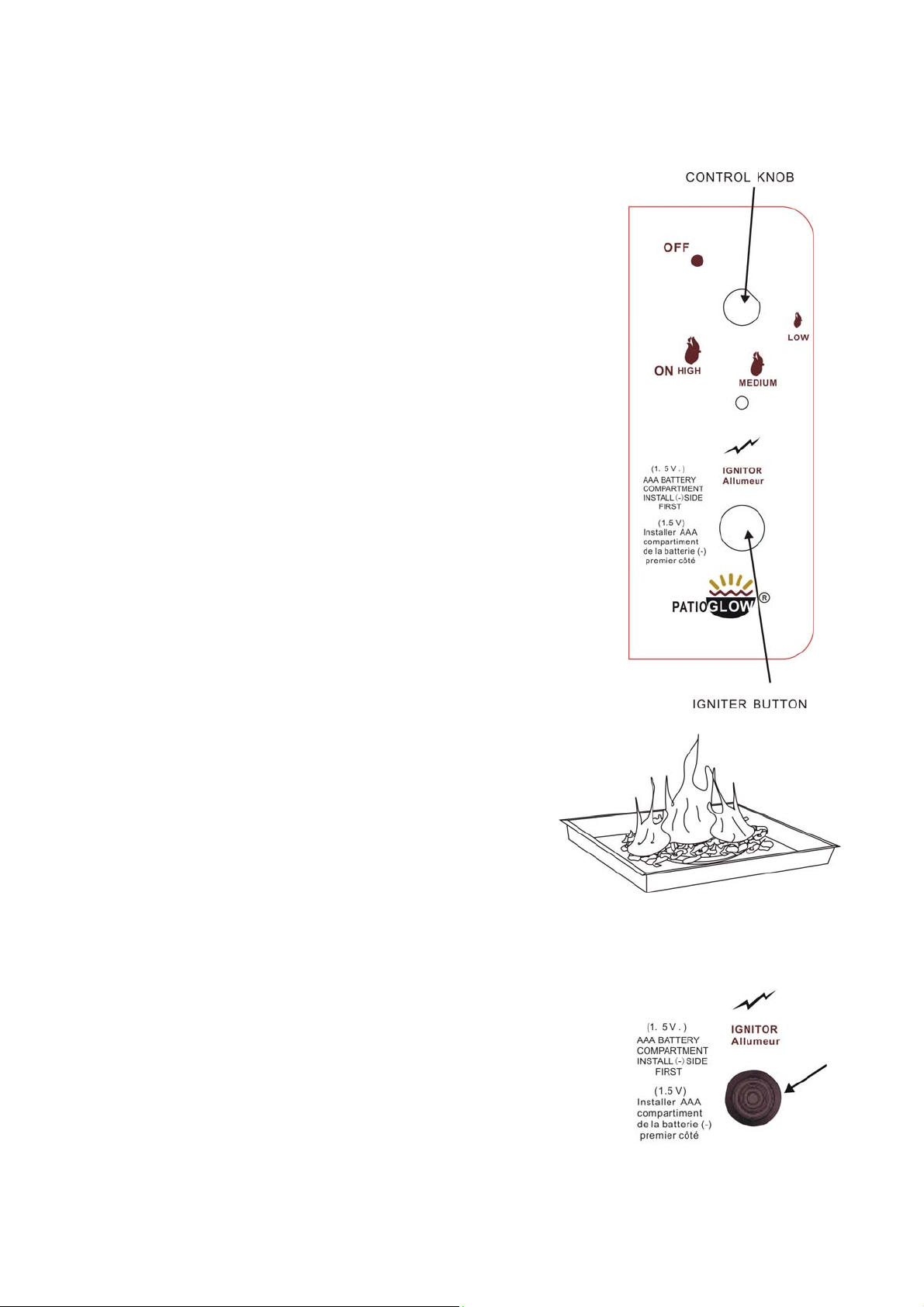
1. Locate the control and igniter panel. Make sure the
control knob is in the “OFF” position. See Figure 10.
Open the tank door and open the tank valve all the way.
2. Push in the igniter button. You will hear a slight clicking
sound. With the igniter button pushed in, push and turn
the control knob to the “ON” position. The fire should
light within a few seconds. Once the flame is lit, release
the igniter button and continue to hold the control knob
in for 10 to 15 seconds. Release the control knob. The
control knob should pop back out and the fire should
remain lit. Note: If the fire does not light, turn the knob
to the “OFF” position and wait five (5) minutes before
trying again.
3. To turn down the flame, push the control knob in slightly
and turn to the Medium (medium flame) or Low (small
flame).
4.To shut down the fire pit, turn the control knob to the
“OFF” position and turn off the tank valve
Figure 10
MAINTENANCE
The flames should look like those in Figure 1 1. To
clean the burner, use a sof t brush after the burner
and lava rocks have cooled completely. Never
use a vacuum cleaner on the lava rocks. It is
recommended that the lava rocks be stored
indoors during the winter if they will be subjected
to freezing temperatures. The propane cylinder
must be disconnected and removed from the
appliance before the appliance can be stored
indoors.
BATTERIES
Make sure the control knob is in the “OFF” position.
Unscrew the push button cap on the ignition module
located on the control panel to access the battery
compartment. The ignition module requires one AAA size
battery. See Figure 12.
Figure 11
Figure 12
Page 14

TROUBLESHOOTING GUIDE
PROBLEM CAUSE REMEDY
Check that gas tank valve is open.
No Propane Gas at Burner
Turn control knob to “ON” and push
control knob in. Make sure tank has
propane gas.
Burner won’t light
Burner won’t stay
lit after lighting
No Spark at Electrode
Lack of oxygen
Thermocouple not in flame
Thermocouple connection
at the main control valve is
loose
Check that AAA battery is installed
with negative (-) end first and has a
charge. Check that the wire is
connected to the ignition module.
Check that the electrode is not
cracked or broken.
Remove excess lava rocks or fire ices
from around the ignition well.
Check that the tip of the thermocouple
is even with the top of the ignition
well. Remove any fire ices from the
igntion well.
Tighten the thermocouple nut at the
back of
the valve.
No Fire ice on Burner
Cover the burner with fire ices per the
instructions
 Loading...