

Page 1
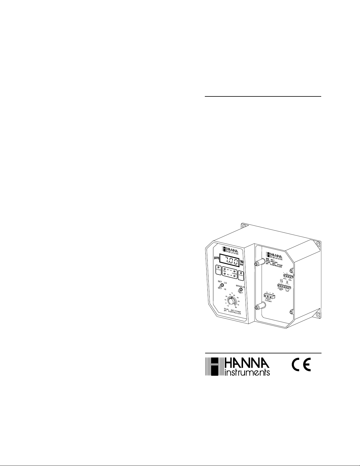
Instruction Manual
WM 8910 - WM 8911
WM 8912 - WM 8913
WM 8920 - WM 8923
WM 8930
Wall Mounted
ORP - pH - Conductivity
Controllers
http://www.hannainst.com
These Instruments are in
Compliance with the CE Directives
Page 2
Dear Customer,
Thank you for choosing a Hanna Product.
Please read this instruction manual carefully before using the instru-
ment. This manual will provide you with the necessary information for
a correct use of the instrument, as well as a more precise idea of its
versatility. If you need more technical information, do not hesitate to
e-mail us at tech@hannainst.com.
These instruments are in compliance with the
EN 50081-1 and 50082-1.
TABLE OF CONTENTSTABLE OF CONTENTS
TABLE OF CONTENTS
TABLE OF CONTENTSTABLE OF CONTENTS
directives
PRELIMINARY EXAMINATIONPRELIMINARY EXAMINATION
PRELIMINARY EXAMINATION
PRELIMINARY EXAMINATIONPRELIMINARY EXAMINATION
Remove the instrument from the packing material and examine it
carefully to make sure that no damage has occurred during shipping.
If there is any noticeable damage, notify your Dealer.
Each wall-mounted meter is supplied complete with a power plug and
an instruction manual.
Note: Save all packing materials until you are sure that the
instrument functions correctly. Any defective item must be
returned in the original packaging together with the supplied
accessories.
PRELIMINARY EXAMINATION........................................................ 3
GENERAL DESCRIPTION ................................................................3
MECHANICAL LAYOUTS ................................................................. 4
FUNCTIONAL DESCRIPTION WM 8910 .......................................... 6
FUNCTIONAL DESCRIPTION WM 8911 .......................................... 9
FUNCTIONAL DESCRIPTION WM 8912 ........................................ 12
FUNCTIONAL DESCRIPTION WM 8913 ........................................ 14
FUNCTIONAL DESCRIPTION WM 8920 ........................................ 16
FUNCTIONAL DESCRIPTION WM 8923 ........................................ 18
FUNCTIONAL DESCRIPTION WM 8930 ........................................ 20
OPERATIONAL GUIDE ................................................................. 23
pH CALIBRATION ....................................................................... 27
ORP CALIBRATION ..................................................................... 28
CONDUCTIVITY CALIBRATION......................................................29
ADJUSTEMENT OF SETPOINT(S)..................................................31
pH VALUES AT VARIOUS TEMPERATURES...................................37
TAKING REDOX MEASUREMENTS................................................. 38
ELECTRODE CONDITIONING AND MAINTENANCE...........................40
SUGGESTED INSTALLATIONS FOR pH/ORP ELECTRODES...............43
CONDUCTIVITY PROBE MAINTENANCE & CLEANING...................... 45
ACCESSORIES.............................................................................45
WARRANTY ................................................................................ 53
CE DECLARATION OF CONFORMITY .............................................. 55
ISO 9000 Certified
Company since 1992
2
IMPORTANT:
1. Read the instructions before using the instrument.
2. Check that the voltage rating at the back of the instrument
corresponds to your mains voltage.
3. The instrument should be connected to a mains socket.
4. Never immerse the instrument in water.
5. The instrument is protected by a 2A fuse. Use only a 2A fuse to
replace it.
GENERAL DESCRIPTIONGENERAL DESCRIPTION
GENERAL DESCRIPTION
GENERAL DESCRIPTIONGENERAL DESCRIPTION
Hanna's wall-mounted pH, ORP and conductivity controllers
specifically designed to meet your process control requirements.
The controllers come equipped with power relays operating at a
maximum of 2A (240V).
Electrodes and probes can be installed quickly and easily. Simply plug
the universal BNC or DIN connector into the socket (and twist it into
a secured position).
Accurate measurements are displayed on a large LCD.
The Hanna WM series of controllers incorporate a triple contact alarm
system. When activated, the alarm contacts will open or close,
triggering the mechanism of your choice, whether a buzzer, light or
any other electrical device.
3
are
Page 3
The recorder output terminals are isolated from the controller circuitry
to avoid any interference and are user-switchable between 0 to 20
mA or 4 to 20 mA.
These controllers are housed in a rugged, modular, fiber-reinforced
polypropylene housing.
When in operation, and with the transparent cover installed, the
units comply with the IP 54 standards.
All available models can be supplied in the 110/115V ("Part No./U")
or 220/240V ("/D") version.
Six models are available:
WM 8910 a single setpoint pH controller
WM 8911 a dual setpoint pH controller, specifically designed for
all those applications in which the pH value intends to
oscillate both up and down
WM 8912 pH and ORP controller, designed for numerous
industrial applications, but in particular for swimming
pools and drinking water sanitation
WM 8913 pH and conductivity controller,
designed primarily
for agricultural applications
WM 8920 a single setpoint ORP controller
WM 8923 pH and conductivity controller
for various applications especially in water heating/conditioning systems
(where, due to evaporation, alkalinity tends to increase)
WM 8930 conductivity controller, designed for industrial appli-
cations, especially water heating/conditioning systems.
MECHANICAL LAYOUTSMECHANICAL LAYOUTS
MECHANICAL LAYOUTS
MECHANICAL LAYOUTSMECHANICAL LAYOUTS
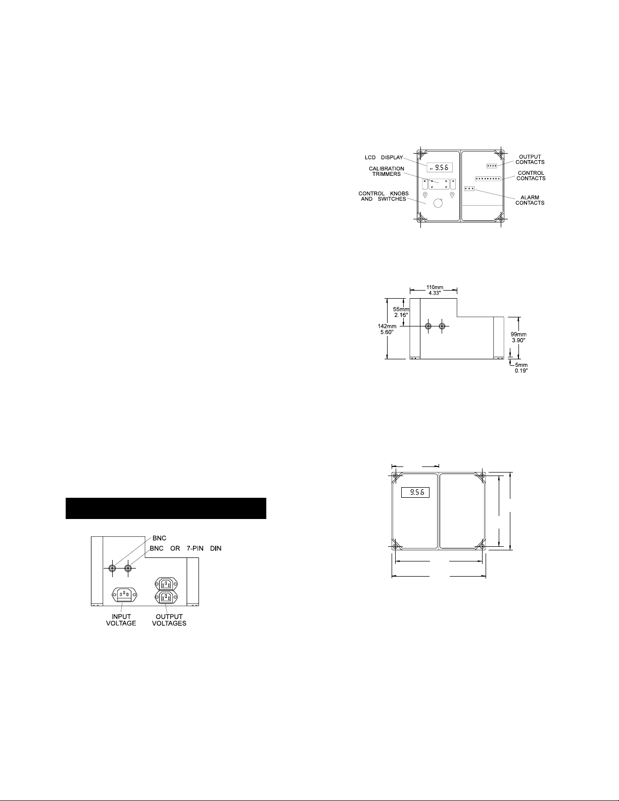
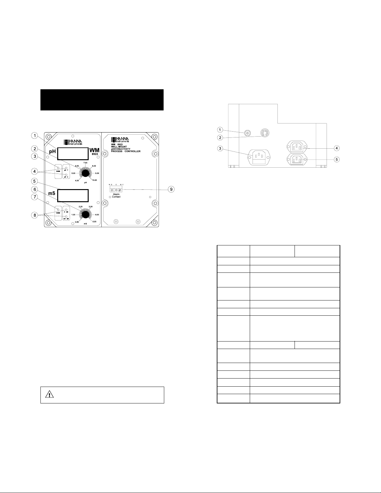
Fig. 2
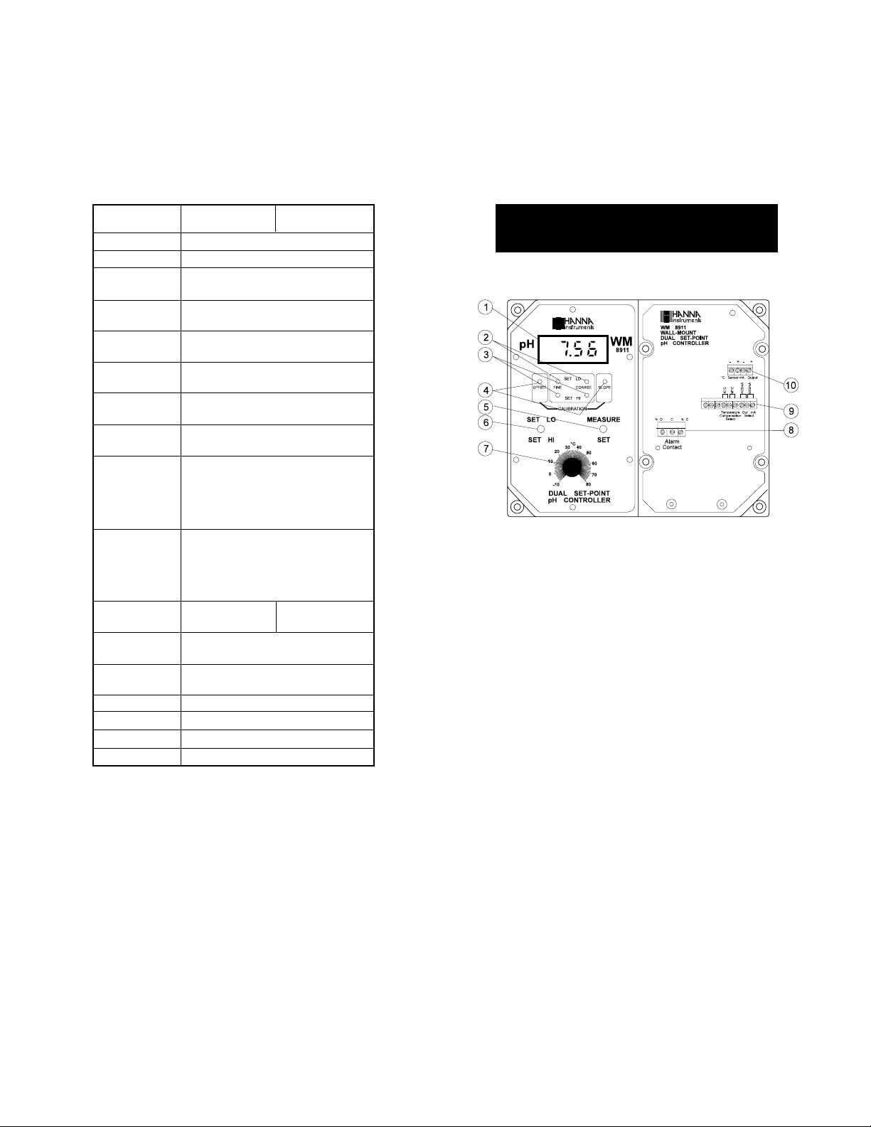
Figure 2 illustrates the arrangement of the controls and contacts on
the pH controller, WM 8911. Layouts vary from model to model
based on their features and capabilities.
Fig. 3
Figure 3 is a dimensioned, bottom view of the Wall Mounted
Controller. The modular design isolates the control circuitry from the
contacts making it possible to make the connections and then seal the
compartment. Adjustments can then be made only in the control
area, without having to open the contacts compartment and run the
risk or interfering with the connections.
110mm
4.33"
pH
181mm
7.13"
164mm
6.45"
Fig. 1
Figure 1 displays the connectors for probes and electrodes, output
voltages for pumps, and input voltage for the power cord.
4
204mm
8.03"
221mm
8.70"
Fig. 4
Figure 4 is a dimensioned front view of the Wall Mounted Controller.
The molded, mounting holes in the corners provide quick, simple and
secure installation. No additional hardware is needed for mounting.
All electrical connections and controls are located on the front of the
instrument so that adjustment can be made without removing the
unit from the wall.
5
Page 4
FUNCTIONAL DESCRIPTION WM 8910FUNCTIONAL DESCRIPTION WM 8910
FUNCTIONAL DESCRIPTION WM 8910
FUNCTIONAL DESCRIPTION WM 8910FUNCTIONAL DESCRIPTION WM 8910
SINGLE SETPOINT, SINGLE SETPOINT,
SINGLE SETPOINT,
SINGLE SETPOINT, SINGLE SETPOINT,
pp
p
pp
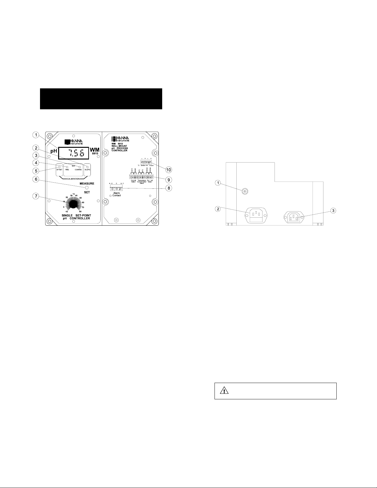
FRONT PANEL
H CONTROLLERH CONTROLLER
H CONTROLLER
H CONTROLLERH CONTROLLER
– Three terminals marked "Out mA Select" to select between
0 to 20 mA or 4 to 20 mA isolated output.
10. Output contacts:
– Two terminals marked "°C Sensor" for the connection of a
silicon temperature probe for automatic temperature
compensation
– Two terminals marked "mA Output" for the isolated output
BOTTOM CONNECTIONS
Left panel
1. LCD display
2. Slope calibration trimmer
3. Coarse setpoint trimmer
4. Fine setpoint trimmer
5. Offset calibration trimmer
6. Selects actual measurement (MEASURE) or setpoint (SET) to
be displayed on the LCD
7. Graded dial for manual temperature compensation
Right panel
8. Triple contact alarm to select the alarm in a normally-closed
(NC) or a normally open (NO) position. The alarm contact is
activated when the pH varies by more than ±2.0 pH from
the setpoint.
9. Control contacts:
– Three terminals marked "Control Select" to choose acid or
basic dosing
– Three terminals marked "Temperature Compensation Select"
to select automatic (ATC) or manual temperature
compensation mode (MTC)
6
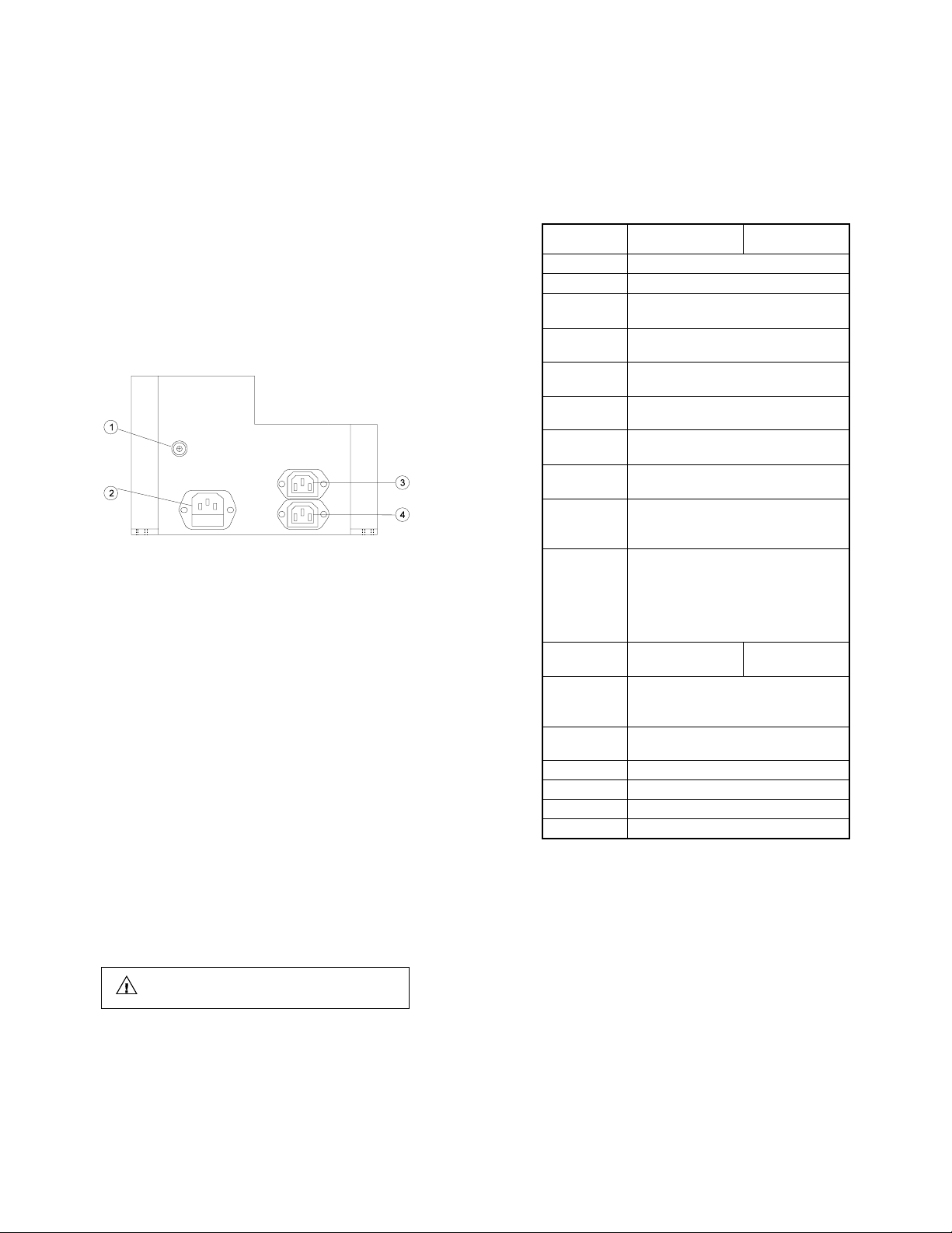
1. BNC socket for a combination pH electrode
2. Input voltage supply socket
3. Output voltage socket (supplies power to a pump or
electrovalve). This socket is activated by a relay when the pH
has not reached the setpoint.
Unplug the instrument from the power supply before
replacing the fuse.
7
Page 5
Specifications WM 8910D WM 8910U
RANGE 0.00 to 14.00 pH
RESOLUTION 0.01 pH
ACCURACY ±0.02 pH
(@20°C/68°F)
TYPICAL EMC ±0.1pH
DEVIATION
mA OUTPUT User selectable 0 to 20 mA or 4 to 20 mA
in a 0-14 pH range with isolated output
OFFSET Through "OFFSET" trimmer
CALIBRATION (Max. ±1.5 pH regulation)
SLOPE Through "SLOPE" trimmer
CALIBRATION from 80% to 110%
TEMPERATURE Manual or automatic
COMPENSATION from -10 to 80°C (14 to 176°F)
SETPOINT From 0.00 to 14.00 pH with 2 trimmers: "COARSE" for
RANGE an approximate regulation and "FINE" for fine tuning.
In addition, setpoint controls are activated through the
"CONTROL SELECT" terminals: "ACID"
or "BASE" for acid or basic dosage.
ALARM Through a relay which provides a normally open or a
CONTACT normally closed contact output (isolated output Max.
2A, Max. 240V, resistive load, 1,000,000 strokes).
The alarm contact will be activated if the pH
varies by more than ±2 pH from setpoint.
POWER SUPPLY 220/240V 110/115V
50/60Hz 50/60Hz
POWER SUPPLY One plug for the pH dosage (115 or 220V, depending
FOR DOSING on the model, Max.2A, 1,000,000 strokes)
ENVIRONMENT -10 to 50°C (14 to 122°F)
max. 85% RH non-condensing
PROTECTION IP54
WEIGHT 1.6 Kg (3.5 lb.)
ENCLOSURE 181 x 221 x 142mm (7.1 x 8.7 x 5.6")
MATERIAL Housed in rugged, fiber-reinforced polypropylene case
FUNCTIONAL DESCRIPTION WM 8911FUNCTIONAL DESCRIPTION WM 8911
FUNCTIONAL DESCRIPTION WM 8911
FUNCTIONAL DESCRIPTION WM 8911FUNCTIONAL DESCRIPTION WM 8911
DUAL SETPOINT, DUAL SETPOINT,
DUAL SETPOINT,
DUAL SETPOINT, DUAL SETPOINT,
pHpH
pH
pHpH
FRONT PANEL
CONTROLLER CONTROLLER
CONTROLLER
CONTROLLER CONTROLLER
Left panel
1. LCD display
2. Fine and Coarse trimmers to precisely set the lower level
3. Fine and Coarse trimmers to precisely set the higher level
4. Offset and Slope calibration trimmers
5. Selects actual measurement (MEASURE) or setpoint (SET) to
be displayed on the LCD
6. Selects "LO" and "HI" setting modes
7. Graded dial for manual temperature compensation
Right panel
8. Triple contact alarm to select the alarm in a normally-closed
(NC) or a normally open (NO) position. The alarm contact is
activated when the pH varies by more than -2.0 pH from
“SET LO” and +2.0 from “SET HI” setpoint values.
9. Control contacts:
– Three terminals marked "Temperature Compensation Select"
to select automatic or manual temperature compensation
mode
– Three terminals marked "Out mA Select" to select between
0 to 20 mA or 4 to 20 mA isolated output.
8
9
Page 6
10. Output contacts:
– Two terminals marked "°C Sensor" for the connection of a
temperature probe for automatic temperature compensation
– Two terminals marked "mA Output" for the isolated output
BOTTOM CONNECTIONS
1. BNC socket for a combination pH electrode
2. Input voltage supply socket
3. Output voltage socket for acid dosing (supplies power to a
pump or electrovalve). This socket is activated by a relay
when the pH is higher than the "SET HI" value.
4. Output voltage socket for alkaline dosing (supplies power to a
pump or electrovalve). This socket is activated by a relay
when the pH value is lower than the "SET LO" value.
Specifications WM 8911D WM 8911U
RANGE 0.00 to 14.00 pH
RESOLUTION 0.01 pH
ACCURACY ±0.02 pH
(@20°C/68°F)
TYPICAL EMC ±0.1 pH
DEVIATION
mA OUTPUT User selectable 0 to 20 mA or 4 to 20 mA
in a 0-14 pH range with isolated output
OFFSET Through "OFFSET' trimmer
CALIBRATION (Max. ±1.5 pH regulation)
SLOPE Through "SLOPE" trimmer
CALIBRATION from 80% to 110%
TEMPERATURE Manual or automatic
COMPENSATION from -10 to 80°C (14 to 176°F)
SETPOINT RANGE From 0.00 to 14.00 pH with 2 trimmers:
"COARSE" for an approximate
regulation, "FINE" for fine tuning.
ALARM CONTACT Through a relay which provides a normally open
or a normally closed contact output (isolated
output Max.2A, Max.240V, resistive load, 1,000,000
strokes). The alarm contact will be activated if the
pH varies by -2.0 pH from "SET LO" and
+2.0 pH from "SET HI" points.
POWER SUPPLY 220/240V 110/115V
50/60Hz 50/60Hz
POWER SUPPLIES One plug for acid and another for alkaline dosage
FOR DOSING (115 or 220V, depending on the model,
Max.2A, 1,000,000 strokes)
ENVIRONMENT -10 to 50°C (14 to 122°F)
max. 85% RH non-condensing
PROTECTION IP54
WEIGHT 1.6 Kg (3.5 lb.)
ENCLOSURE 181 x 221 x 142mm (7.1 x 8.7 x 5.6")
MATERIAL Housed in rugged, fiber-reinforced polypropylene case
Unplug the instrument from the power supply before
replacing the fuse.
10
11
Page 7
FUNCTIONAL DESCRIPTION WM 8912FUNCTIONAL DESCRIPTION WM 8912
FUNCTIONAL DESCRIPTION WM 8912
FUNCTIONAL DESCRIPTION WM 8912FUNCTIONAL DESCRIPTION WM 8912
pHpH
& ORP CONTROLLER & ORP CONTROLLER
pH
& ORP CONTROLLER
pHpH
& ORP CONTROLLER & ORP CONTROLLER
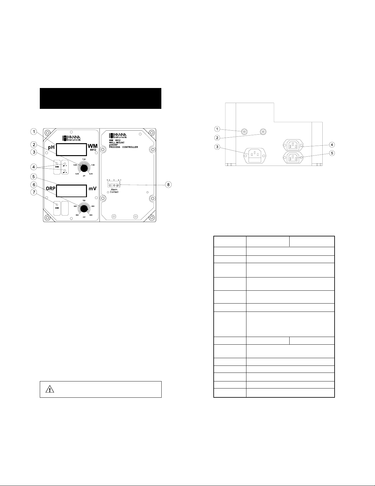
FRONT PANEL
Left panel
1. LCD display for pH measurements
2. Graded dial for setting the pH setpoint (6.00 to 8.00 pH)
3. LED that lights up when the pH dosage is activated.
4. Offset (pH 7) and Slope (pH 4) calibration trimmers
5. LCD display for ORP measurements
6. Graded dial for setting the ORP setpoint (500 to 900 mV)
7. LED that lights up when the ORP dosage is activated.
Note: When both the LEDs are lit up simultaneously, pH takes
priority over ORP dosage.
Right panel
8. Triple contact alarm to select the alarm in a normally closed
(NC) or a normally open (NO) position. The alarm contact is
activated when the pH varies by more than ±2.0 pH from
the setpoint or the ORP by ±200 mV.
Unplug the instrument from the power supply before
replacing the fuse.
12
BOTTOM CONNECTIONS
1. BNC socket for a combination pH electrode
2. BNC socket for a combination ORP electrode
3. Input voltage supply socket
4. Output voltage socket for pH dosing (activated by a relay
when pH is higher than setpoint)
5. Output voltage socket for ORP dosing (activated by a relay
when ORP is lower than setpoint)
Specifications WM 8912D WM 8912U
RANGE 0.00 to 14.00 pH and -1000 to +1000 mV
RESOLUTION 0.01 pH and 1 mV
ACCURACY ±0.02 pH and ±5 mV
(@20°C/68°F)
TYPICAL EMC ±0.1pH
DEVIATION ±6 mV
pH CALIBRATION 2 point through "pH 7" and
"pH 4" trimmers on the front panel
SETPOINT RANGE pH : from 6.00 to 8.00; ORP: from 500 to 900 mV
ALARM CONTACTS Normally open or normally closed isolated
outputs (Max.2A, Max.240V, resistive load, 1,000,000
strokes). Activated if the pH varies by ±2 pH or the
ORP by ±200 mV from setpoints.
POWER SUPPLY 220/240V – 50/60Hz 110/115V – 50/60Hz
POWER SUPPLIES One plug for acid and another for oxidizing
FOR DOSING dosage (115 or 220V, Max.2A, 1,000,000 strokes)
ENVIRONMENT -10 to 50°C (14 to 122°F); max. 85% RH non-condensing
PROTECTION IP54
WEIGHT 1.6 Kg (3.5 lb.)
ENCLOSURE 181 x 221 x 142mm (7.1 x 8.7 x 5.6")
MATERIAL Housed in rugged, fiber-reinforced polypropylene case
13
Page 8

FUNCTIONAL DESCRIPTION WM 8913FUNCTIONAL DESCRIPTION WM 8913
FUNCTIONAL DESCRIPTION WM 8913
FUNCTIONAL DESCRIPTION WM 8913FUNCTIONAL DESCRIPTION WM 8913
pH pH
& CONDUCTIVITY CONTROLLER& CONDUCTIVITY CONTROLLER
pH
& CONDUCTIVITY CONTROLLER
pH pH
& CONDUCTIVITY CONTROLLER& CONDUCTIVITY CONTROLLER
FRONT PANEL
BOTTOM CONNECTIONS
1. BNC socket for a combination pH electrode
2. DIN socket (7-pin) for HI 7637
conductivity probe with ATC
3. Input voltage supply socket
4. Output voltage socket for pH dosing (activated by a relay
when pH is higher than setpoint)
5. Output voltage socket for conductivity control (closed when the
conductivity is higher than setpoint)
Left panel
1. LCD display for pH measurements
2. Graded dial for setting the pH setpoint (4.00 to 10.00 pH)
3. LED that lights up when the pH dosage is activated.
4. Offset (pH 7) and Slope (pH 4) calibration trimmers
5. LCD display for conductivity measurements
6. Graded dial for conductivity setpoint (0.50 to 3.00 mS/cm)
7. LED that lights up when the conductivity dosage is activated
8. Offset (0 mS) and Slope (5.0 mS) calibration trimmers
Right panel
9. Triple contact alarm to select the alarm in a normally closed
(NC) or a normally open (NO) position (activated when the
pH varies by more than ±2.0 pH from the setpoint).
Unplug the instrument from the power supply before
replacing the fuse.
14
Specifications WM 8913D WM 8913U
RANGE 0.00 to 14.00 pH and 0.00 to 19.99 mS/cm
RESOLUTION 0.01 pH and 0.01 mS/cm
ACCURACY ±0.02 pH and ±2% Full Scale
(@20°C/68°F)
TYPICAL EMC ±0.1 pH
DEVIATION ±2% Full Scale
CALIBRATION 2 point for each pH and conductivity
SETPOINT RANGE pH: 4.00 to 10.00; Conductivity: 0.50 to 3.00 mS/cm
ALARM CONTACTS Normally open or normally closed isolated outputs
(Max. 2A, Max. 240V, resistive load, 1,000,000 strokes).
Activated if the pH varies by ±2.0 pH or conductivity
by ±0.5 mS/cm from the setpoints.
POWER SUPPLY 220/240V – 50/60Hz 110/115V – 50/60Hz
POWER SUPPLIES One plug for the pH (acid) and another for conductivity
FOR DOSING control (115 or 220V, Max.2A, 1,000,000 strokes)
ENVIRONMENT -10 to 50°C (14 to 122°F)
max. 85% RH non-condensing
PROTECTION IP54
WEIGHT 1.6 Kg (3.5 lb.)
ENCLOSURE 181 x 221 x 142 mm (7.1 x 8.7 x 5.6")
MATERIAL Housed in rugged, fiber-reinforced polypropylene case
15
Page 9
FUNCTIONAL DESCRIPTION WM 8920FUNCTIONAL DESCRIPTION WM 8920
FUNCTIONAL DESCRIPTION WM 8920
FUNCTIONAL DESCRIPTION WM 8920FUNCTIONAL DESCRIPTION WM 8920
SINGLE SETPOINT ORP CONTROLLERSINGLE SETPOINT ORP CONTROLLER
SINGLE SETPOINT ORP CONTROLLER
SINGLE SETPOINT ORP CONTROLLERSINGLE SETPOINT ORP CONTROLLER
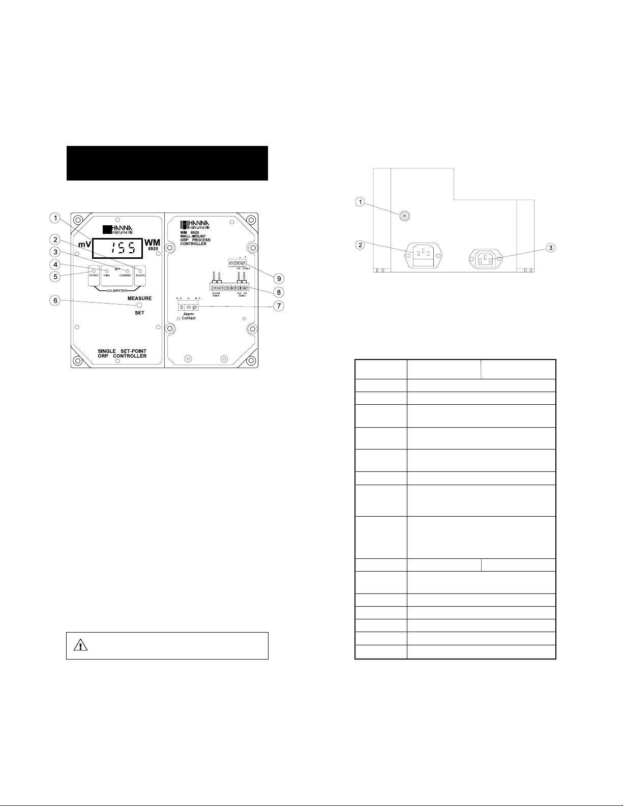
FRONT PANEL
Left panel
1. LCD display
2. Slope calibration trimmer
3. Coarse set point trimmer
4. Fine set point trimmer
5. Offset calibration trimmer
6. Selects actual measurement (MEASURE) or setpoint (SET) to
be displayed on the LCD
Right panel
7. Triple contact alarm to select the alarm in a normally-closed
(NC) or a normally open (NO) position. The alarm contact is
activated when the mV varies by more than ±200 mV from
the setpoint.
8. Control contacts:
– Three terminals marked "Control Select" to choose REDOX or
OXYDT for dosing reducing or oxidant chemicals
– Three terminals marked "Out mA Select" to select between
0 to 20 mA or 4 to 20 mA isolated output.
9. Output contacts:
– Two terminals marked "mA Output" for the isolated output
Unplug the instrument from the power supply before
replacing the fuse.
BOTTOM CONNECTIONS
1. BNC socket for a combination ORP electrode
2. Input voltage supply socket
3. Output voltage socket (activated by a relay when the
measured reading is higher or lower than the setpoint
depending on the REDOX/OXYDT selection)
Specifications WM 8920D WM 8920U
RANGE -1000 to 1000 mV
RESOLUTION 1 mV
ACCURACY ±5 mV
(@20°C/68°F)
TYPICAL EMC ±6 mV
DEVIATION
mA OUTPUT User selectable 0 to 20 mA or 4 to 20 mA in
a -1000 to 1000 mV range with isolated output
CALIBRATION 2 point through trimmers
SETPOINT RANGE From -1000 to 1000 mV with 2 trimmers: "COARSE" and
"FINE" (activated through the "CONTROL SELECT" terminals:
"OXYDT" or "REDOX" for the oxidizing or reducing dosage)
ALARM CONTACT Normally open or normally closed isolated outputs
(Max. 2A, Max. 240V, resistive load, 1,000,000 strokes)
(activated when the ORP value varies by
more than ±200 mV from setpoint)
POWER SUPPLY 220/240V – 50/60Hz 110/115V – 50/60Hz
POWER SUPPLIES One plug for the oxidizing or reducing dosage (115 or 220V
FOR DOSING depending on the model, Max. 2A, 1,000,000 strokes)
ENVIRONMENT -10 to 50°C (14 to 122°F); max. 85% RH non-condensing
PROTECTION IP54
WEIGHT 1.6 Kg (3.5 lb.)
ENCLOSURE 181 x 221 x 142mm (7.1 x 8.7 x 5.6")
MATERIAL Housed in rugged, fiber-reinforced polypropylene case
16
17
Page 10
FUNCTIONAL DESCRIPTION WM 8923FUNCTIONAL DESCRIPTION WM 8923
FUNCTIONAL DESCRIPTION WM 8923
FUNCTIONAL DESCRIPTION WM 8923FUNCTIONAL DESCRIPTION WM 8923
pH pH
& CONDUCTIVITY CONTROLLER& CONDUCTIVITY CONTROLLER
pH
& CONDUCTIVITY CONTROLLER
pH pH
& CONDUCTIVITY CONTROLLER& CONDUCTIVITY CONTROLLER
FRONT PANEL
Left panel
1. LCD display for pH measurements
2. Graded dial for setting the pH setpoint (4.00 to 10.00 pH)
3. LED that lights up when the pH dosage is activated.
4. Offset (pH 7) and Slope (pH 4) calibration trimmers
5. LCD display for conductivity measurements
6. Graded dial for conductivity setpoint (0.50 to 5.00mS/cm)
7. LED that lights up when the conductivity dosage is activated.
8. Offset (0 mS) and Slope (5.0 mS) calibration trimmers
Right panel
9. Triple contact alarm to select the alarm in a normally closed
(NC) or a normally open (NO) position. The alarm contact is
activated when the pH varies by more than ±2.0 pH from
the setpoint or the conductivity by more than ±0.5 mS/cm
from its setpoint.
Unplug the instrument from the power supply before
replacing the fuse.
BOTTOM CONNECTIONS
1. BNC socket for a combination pH electrode
2. DIN socket (7-pin) for HI 7637
conductivity probe with ATC
3. Input voltage supply socket
4. Output voltage socket for pH dosing (supplies power to a
pump or electrovalve). This socket is activated by a relay
when the pH is higher than the setpoint.
5. Output voltage socket for conductivity control. This contact is
automatically closed when the conductivity value is higher
than the setpoint.
Specifications WM 8923D WM 8923U
RANGE 0.00 to 14.00 pH and 0.00 to 19.99 mS/cm
RESOLUTION 0.01 pH and 0.01 mS/cm
ACCURACY ±0.02 pH and ±2% Full Scale
(@20°C/68°F)
TYPICAL EMC ±0.1 pH
DEVIATION ±2% Full Scale
CALIBRATION 2 point for each pH and conductivity
SETPOINT RANGE pH : 4.00 to 10.00; Conductivity: 0.0 to 5.00 mS/cm
ALARM CONTACTS Normally open or normally closed isolated outputs
POWER SUPPLY 220/240V – 50/60Hz 110/115V – 50/60Hz
POWER SUPPLIES One plug for pH (acid) and another for conductivity
FOR DOSING control (115 or 220V, Max. 2A, 1,000,000 strokes)
ENVIRONMENT -10 to 50°C (14 to 122°F); max. 85% RH non-condensing
PROTECTION IP54
WEIGHT 1.6 Kg (3.5 lb.)
ENCLOSURE 181 x 221 x 142mm (7.1 x 8.7 x 5.6")
MATERIAL Housed in rugged, fiber-reinforced polypropylene case
(Max. 2A, Max.240V, resistive load, 1,000,000 strokes)
(activated if the pH varies by ±2 pH or the
conductivity by ±0.5 mS/cm from the setpoints.
18
19
Page 11

FUNCTIONAL DESCRIPTION WM 8930FUNCTIONAL DESCRIPTION WM 8930
FUNCTIONAL DESCRIPTION WM 8930
FUNCTIONAL DESCRIPTION WM 8930FUNCTIONAL DESCRIPTION WM 8930
CONDUCTIVITY CONTROLLERCONDUCTIVITY CONTROLLER
CONDUCTIVITY CONTROLLER
CONDUCTIVITY CONTROLLERCONDUCTIVITY CONTROLLER
FRONT PANEL
BOTTOM CONNECTIONS
Left panel
1. LCD display
2. Slope calibration trimmer
3. Coarse trimmer to adjust the setpoint
4. Fine trimmer to precisely adjust the set-point
5. Offset calibration trimmer
6. Selects actual measurement (MEASURE) or setpoint (SET) to
be displayed on the LCD
Right panel
7. Triple contact alarm to select the alarm in a normally closed
(NC) or a normally open (NO) position. The alarm contact is
activated when the conductivity varies by more than
±500 µS/cm from the setpoint.
8. Control contacts:
– Three terminals marked "Control Select" to select HI or
LOW for dosing selection
– Three terminals marked "Out mA Select" to select between
0 to 20 mA or 4 to 20 mA isolated output
9. Output contacts:
– Two terminals marked "mA Output" for the isolated output
1. DIN socket for HI 7637
2. Input voltage supply socket
3. Output voltage socket. This socket is activated by a relay
when the measured reading is higher or lower than the
setpoint depending on the HI/LO selection.
Unplug the instrument from the power supply before
replacing the fuse.
conductivity probe
20
21
Page 12

Specifications WM 8930D WM 8930U
RANGE 0 to 10,000 µS/cm
RESOLUTION 1 µS/cm
ACCURACY ±2% Full Scale
(@20°C/68°F)
TYPICAL EMC ±2% Full Scale
DEVIATION
mA OUTPUT User selectable 0 to 20 mA or 4 to 20 mA in
a 0 to 10000 µS/cm range with isolated output
CALIBRATION 2 point through trimmers on the front panel
TEMPERATURE Automatic with ß of 2% per °C
COMPENSATION
SETPOINT RANGE From 0 to 10,000 µS/cm with 2 trimmers: "COARSE" for
an approximate regulation and "FINE" for fine tuning.
In addition, setpoint contacts are activated through the
"CONTROL SELECT" terminals: "HI" or "LO" for increasing
or reducing the conductivity.
ALARM CONTACT Through a relay which provides a normally open or a
normally closed contact output (isolated output Max.2A,
Max.240V, resistive load, 1,000,000 strokes). The alarm
contact activates when the conductivity value varies by
more than ±500 µS/cm from setpoint.
POWER SUPPLY 220/240V 110/115V
50/60Hz 50/60Hz
POWER SUPPLIES One plug for the high or low conductivity
FOR DOSING dosage (115 or 220V, depending on
the model, Max.2A, 1,000,000 strokes)
ENVIRONMENT -10 to 50°C (14 to 122°F)
max 85% RH non-condensing
PROTECTION IP54
WEIGHT 1.6 Kg (3.5 lb.)
ENCLOSURE 181 x 221 x 142mm (7.1 x 8.7 x 5.6")
MATERIAL Housed in rugged, fiber-reinforced polypropylene case
OPERATIONAL GUIDEOPERATIONAL GUIDE
OPERATIONAL GUIDE
OPERATIONAL GUIDEOPERATIONAL GUIDE
ELECTRICAL & PROBE CONNECTIONS
• Connect the power cable (HI 767/P) to the input voltage supply
socket on the bottom of the meter (see functional description).
• Connect the pH or/and ORP electrode(s) to the BNC socket(s)
provided (for WM 8912 only, the BNC for the pH electrode is on
the left and the BNC for the ORP one on the right) and located
on the bottom of the meter.
• Connect the HI 7637 conductivity probe to the
DIN socket (for WM 8913, WM 8923 and WM 8930)
located on the bottom of the meter, by aligning the
pins with the socket, pushing the plug in and
tightening the threaded ring.
• Connect the external device/s (a pump or an electrovalve) through
HI 7671 output plug to the output socket/s (just one for
WM 8910, WM 8920 and WM 8930 or two for WM 8911,
WM 8912, WM 8913, WM 8923) located on the bottom of the
meter. The selected operation will be activated by the gauge
relay/s (see page 31 for more information).
22
ALARM & RECORDER CONNECTIONS
• If the reading drifts from the setpoint as specified on the next
page or if the unit loses power an external alarm is activated. It
can be selected normally closed ("NC") by connecting the external
device to the C and NC terminals or normally open ("NO") by
connecting the external device to the C and NO terminals.
23
Page 13

When activated, the alarm contacts will open or close, triggering
the mechanism of your choice, whether a buzzer, light or any
other electrical devices (the alarm is a necessity specially with
installation in remote locations or when corrective action must be
taken immediately).
TEMPERATURE COMPENSATION
(for WM 8910 and WM 8911 only)
• Manual temperature compensation
ing the MTC to the middle terminal. The temperature is then to
be manually adjusted with the temperature dial.
can be selected by short-
Model Alarm is activated when the reading varies:
WM 8910 ±2.0 pH from the setpoint
WM 8911 -2.0 pH lower than the SET LO or +2.0 pH higher than the SET HI
WM 8912 ±2.0 pH from the setpoint; ±200 mV from the setpoint
WM 8913 ±2.0 pH from the setpoint; ±0.5 mS/cm from the setpoint
WM 8920 ±200 mV from the setpoint
WM 8923 ±2.0 pH from the setpoint; ±0.5 mS/cm from the setpoint
WM 8930 ±500 µS/cm from the setpoint
• The recorder output terminals (for WM 8910, WM 8911,
WM 8920 and WM 8930 only) are isolated from the controller
circuitry to avoid any interference. They are user-switchable
between 0 to 20 mA or 4 to 20 mA as shown below and are
proportional to the measured pH, ORP or conductivity values.
OR
• Automatic temperature compensation
can be selected by
shorting the ATC and the middle terminal. Cut off the connector of
a HI 7669/2W temperature probe (optional). Strip the two wires
and connect them to the “°C sensor” terminals of the output
contacts.
TAKING MEASUREMENTS
Make sure that the controller together with the electrode or probe has
been calibrated before operating the instruments (see following
pages).
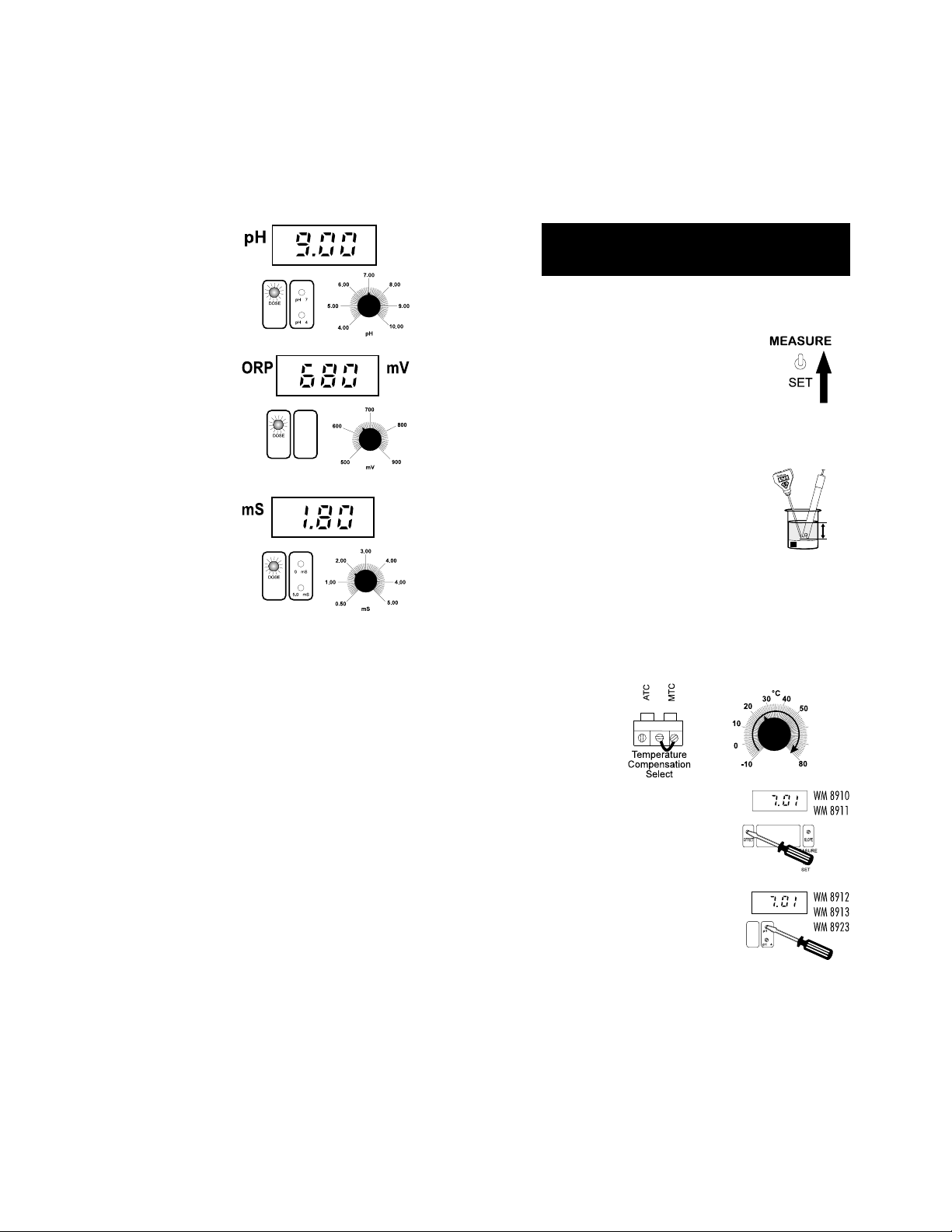
Adjust the pH, ORP or conductivity setpoint(s) following the instructions on page 31.
Immerse the electrode and/or probe in the test solution and set the
switch to "MEASURE" (for WM 8910, WM 8911, WM 8920 and
WM 8930 only).
24
The actual pH, ORP or conductivity value of the test solution will be
displayed.
25
Page 14
When the meter is in pH
dosage mode and the terminals are activated, the
DOSE LED will be lit
(for
WM 8912, WM 8913
and WM 8923 only).
Likewise for the DOSE LED
of the ORP controller
WM 8912.
Similarly, DOSE LED of
WM 8913 and WM 8923
will be lit when conductivity terminals are activated.
Note: When both the LEDs are lit up simultaneously, the pH dosage
is given priority over ORP/conductivity dosage.
pH pH
CALIBRATION CALIBRATION
pH
CALIBRATION (for WM 8910, WM 8911,
pH pH
CALIBRATION CALIBRATION
WM 8912, WM 8913, WM 8923 only)
Make sure a combination pH electrode is connected to the BNC socket
and the meter is plugged to the mains.
Turn the switch to the "MEASURE" position.
The calibration should be ideally performed at
the temperature of the liquid that is being
controlled.
Use a ChecktempC (or an accurate thermometer) as reference for a
temperature compensated calibration.
OFFSET ADJUSTMENT:
• Remove the protective cap from the electrode, rinse it with some pH 7.01 solution
(HI7007), then dip it in pH 7.01 buffer.
Note: The electrode should be submerged approximately 4 cm (1½")
into the solution. The thermometer should be located close to
the pH electrode.
For WM 8910 and WM 8911 only:
• Short the MTC and the middle terminals and adjust the "°C"
knob to the temperature of the solution (e.g. 25°C).
°C
(1½
4 cm
")
HI 7007
26
• Stir the electrode and wait about one
minute before adjusting the "OFFSET"
or the "pH7" trimmer to display pH 7.01
on the LCD if the temperature of the
buffer solution is at 25°C (77°F).
• If the temperature of the buffer solution is not 25°C (77°F), refer to the
chart on page 37 for the appropriate
buffer value at a given temperature.
27
Page 15

SLOPE ADJUSTMENT:
°C
• Rinse the electrode thoroughly in water
and immerse it in pH 4.01 (HI 7004)
or pH 10.01 (HI 7010) buffer solution.
HI 7004
(1
4 cm
½
")
Note: Use pH 4.01 if you are going to measure acidic samples or pH
10.01 for alkaline measurements.
• Stir the electrode and wait about
one minute before adjusting the
"SLOPE" or "pH 4" trimmer to
display pH 4.01 (or 10.01) on
the LCD if the temperature of the
buffer solution is at 25°C (77°F).
Otherwise, refer to the chart on
page 37 for appropriate buffer
value corresponding to the buffer
temperature temperature.
The pH calibration is now complete.
ORP CALIBRATIONORP CALIBRATION
ORP CALIBRATION
ORP CALIBRATIONORP CALIBRATION
(WM 8920 only)
Make sure a combination ORP electrode is connected to the BNC socket
and the meter is plugged to the mains.
For WM 8912 only:
ORP calibration is not required, however, you can check the correct
functioning of the ORP electrode by immersing it into a HI 7020
solution. The controller should read in the 200 to 275 mV range. If
necessary follow cleaning and maintenance procedures described on
page 40.
CONDUCTIVITY CALIBRATION CONDUCTIVITY CALIBRATION
CONDUCTIVITY CALIBRATION (for
CONDUCTIVITY CALIBRATION CONDUCTIVITY CALIBRATION
WM 8913, WM 8923 and WM 8930 only)
Make sure the HI 7637
socket and the meter is plugged to the mains. The calibration should
be ideally performed at the temperature of the liquid that is being
controlled.
PROCEDURE:
• Ensure that the probe is connected to the meter securely by
aligning the pins with the socket, pushing the plug in and
tightening the threaded ring.
• Insert and screw the probe into the PVC
sleeve with the holes towards the top
(the end nearest to the cable).
conductivity probe is connected to the DIN
• Turn the switch to the "MEASURE" position.
• Immerse the electrode in HI 7020
solution.
ORP
HI 7020
(1
4 cm
½
")
• Adjust the slope trimmer until
an ORP value of between 200
mV and 250 mV is displayed.
Note: The ORP offset point is factory calibrated. You can however readjust
the offset by shorting the ORP input connector on the controller
and turning the offset trimmer if necessary to read 0 mV.
28
• Turn the switch to the "MEASURE" position.
• With the conductivity probe in air, adjust the "OFFSET" or "0mS"
trimmer.
29
Page 16

• Immerse the probe into a beaker with a
known calibration solution preferably close
to the value of the sample stream
(HI 7039L at 5000 µS/cm is recommended for slope calibration). The level of
solution must be higher than the holes
on the PVC sleeve.
• Tap the probe repeatedly on the bottom of the beaker and stir it
to ensure that no air bubbles are trapped inside the sleeve.
• When the reading stabilizes, turn the "SLOPE" or the "5.0 mS"
trimmer until the LCD reading is the same of the calibration
solution at the liquid temperature.
• If the instrument will not calibrate refer to the Probe Maintenance
and Cleaning section (see page 45).
ADJUSTEMENT OF SETPOINT(S)ADJUSTEMENT OF SETPOINT(S)
ADJUSTEMENT OF SETPOINT(S)
ADJUSTEMENT OF SETPOINT(S)ADJUSTEMENT OF SETPOINT(S)
Make sure that the controller with the electrode or probe installed is
calibrated before operating (see pages 27-30).
FOR WM 8910
Turn the switch to the "SET" position. The display will show the set
value (e.g. pH 8.00).
Using a small screwdriver, first adjust the setpoint through the
COARSE trimmer, then fine tune it to your required level with the
FINE trimmer until the desired set value is displayed (e.g. pH 6.00).
30
HOW TO SELECT THE DOSING DIRECTION
Select the direction of dosing through the "CONTROL
SELECT" terminals. For an acid dosage short the
"ACID" and common terminals.
For an alkaline dosage, short the "BASE" with the
common (middle) terminal.
E.g. How to dose acidic liquids
Setpoint = pH 6.00
Measured value = pH 7.00
To reach the setpoint you need to dose acid, therefore
connect the "ACID" to the middle terminal of "CONTROL
SELECT".
31
Page 17

E.g. How to dose base liquids
Set point = pH 6.00
Measured value = pH 4.00
To adjust the sample stream to the setpoint, you need
to dose base, therefore short "BASE" to the common
terminal.
Note:
• The FINE trimmer can adjust up to ±1.5 pH.
• Should you use the WM 8911
suggested to adjust the SET LO trimmer to 0.00 pH if you are
only dosing acid solutions, and the SET HI to 14.00 pH if you are
only dosing basic solutions.
for a single-point dosage, it is
FOR WM 8911 (DUAL-POINT ADJUSTMENT)
a) SET LO Adjustment
Turn the switches to the "SET" and "SET LO" positions. The display
will show the 1st setpoint (e.g. pH 4.00).
Using a small screwdriver, first adjust the setpoint through the
COARSE trimmer, then fine tune it to your required level with the
FINE trimmer until the desired set value is displayed (e.g. pH 5.00).
a) SET HI Adjustment
Turn the HI/LO switch to "SET HI" (with the other switch in the "SET"
position). The display will show the 2nd setpoint (e.g. pH 8.00).
Using a small screwdriver, first adjust the setpoint through the
COARSE trimmer, then fine tune it to your required level with the
FINE trimmer until the desired set value is displayed (e.g. pH 6.00).
FOR WM 8912 (pH & ORP)
a) pH setpoint
Adjust the graded dial to the desired setpoint from 6.00 to 8.00 pH.
a) ORP setpoint
Adjust the graded dial to the desired setpoint from 500 to 900 mV.
FOR WM 8913 (pH & CONDUCTIVITY)
a) pH setpoint
Adjust the graded dial to the desired setpoint from 4.00 to 10.00
pH.
32
33
Page 18

a) mS/cm set point
Adjust the graded dial to the desired set point position. The
conductivity set point can be set between 0.50 and 3.00 mS/cm.
FOR WM 8920
Turn the switch to the "SET" position. The display will show the set
value (e.g. mV 650).
Using a small screwdriver, first adjust the setpoint through the
COARSE trimmer, then fine tune it to your required level with the
FINE trimmer until the desired set value is displayed (e.g. mV 700).
E.g. How to dose reducing substances
Setpoint = mV 650
Measured value = mV 700
To reach the setpoint you need to dose reductants,
therefore short "REDOX" with the common (middle) terminal of "CONTROL SELECT".
E.g. How to dose oxidizing substances
Setpoint = mV 650
Measured value = mV 350
To reach the setpoint, you need to dose oxidants,
therefore short "OXYDT" with the common terminal.
FOR WM 8923 (pH & CONDUCTIVITY)
a) pH setpoint
Adjust the graded dial to the desired set point from 4.00 to
10.00 pH.
HOW TO SELECT THE DOSING DIRECTION
Select the direction of dosing through the "CONTROL
SELECT" terminals. For a reducing dosage, short the
"REDOX" terminal with the common terminal in the
middle of "CONTROL SELECT".
For an oxidizing dosage, short the "OXYDT" terminal
with the common (middle) terminal.
34
a) mS/cm setpoint
Adjust the graded dial to the desired setpoint from 0.50 to
5.00 mS/cm.
35
Page 19

FOR WM 8930
Turn the switch to the "SET" position. The display will show the set
value (e.g. 5500 µS/cm).
Using a small screwdriver, first adjust the setpoint through the
COARSE trimmer, then fine tune it to your required level with the
FINE trimmer until the desired set value is displayed
(e.g. 5000 µS/cm).
How to select the dosing direction
Select the direction of dosing through the "CONTROL
SELECT" terminals. To increase the conductivity, short the
"HI" terminal with the common terminal in the middle of
"CONTROL SELECT".
For a dosage to reduce the conductivity short the "LO"
terminal with the common (middle) terminal.
pHpH
VALUES AT VARIOUS VALUES AT VARIOUS
pH
VALUES AT VARIOUS
pHpH
VALUES AT VARIOUS VALUES AT VARIOUS
TEMPERATURESTEMPERATURES
TEMPERATURES
TEMPERATURESTEMPERATURES
Temperature has an effect on measuring pH with conventional
systems. The calibration buffer solutions are affected by temperature
changes to a lesser degree than normal solutions.
Please refer to the following chart to perform the pH calibration more
accurately:
TEMP pH VALUES
°C °F 4.01 6.86 7.01 9.18 10.01
0
32
4.01
6.98
7.13
9.46
10.32
5
41
4.00
6.95
7.10
9.39
10.24
10
50
4.00
6.92
7.07
9.33
10.18
15
59
4.00
6.90
7.04
9.27
10.12
20
68
4.00
6.88
7.03
9.22
10.06
25
77
4.01
6.86
7.01
9.18
10.01
30
86
4.02
6.85
7.00
9.14
9.96
35
95
4.03
6.84
6.99
9.10
9.92
40
104
4.04
6.84
6.98
9.07
9.88
45
113
4.05
6.83
6.98
9.04
9.85
50
122
4.06
6.83
6.98
9.01
9.82
55
131
4.07
6.84
6.98
8.99
9.79
60
140
4.09
6.84
6.98
8.97
9.77
65
149
4.11
6.85
6.99
8.95
9.76
70
158
4.12
6.85
6.99
8.93
9.75
E.g. How to dose conductive solutions
Setpoint = 5000 µS/cm
Measured value = 900 µS/cm
To reach the setpoint you need to dose high conductivity
solutions, therefore short "HI" to the middle terminal of
"CONTROL SELECT".
E.g. How to dose reducing conductivity solution
Setpoint = 5000 µS/cm
Measured value = 7500 µS/cm
To reach the setpoint you need to dose low conductivity
solutions, therefore short the "LO" to the middle terminal
of "CONTROL SELECT".
36
For instance, if the buffer temperature is 25°C (77°F), calibrate the
meter to read 4.01 or 7.01 or 10.01 on the display.
If the buffer temperature is 20°C, calibrate it to read 4.00/7.03/
10.06.
If the buffer temperature is 50°C, calibrate it to read 4.06/6.98/
9.82.
37
Page 20

TAKING REDOX MEASUREMENTSTAKING REDOX MEASUREMENTS
TAKING REDOX MEASUREMENTS
TAKING REDOX MEASUREMENTSTAKING REDOX MEASUREMENTS
(for WM 8912 and WM 8920 only)
Redox measurements allow the quantification of the oxidizing or
reducing power of a solution, and are commonly expressed in mV.
Oxidation may be defined as the process during which a molecule (or
an ion) loses electrons and reduction as the process by which electrons
are gained.
Oxidation is always coupled together with reduction so that as one
element gets oxidized, the other is automatically reduced, therefore
the term oxidation-reduction is frequently used.
Redox potentials are measured by an electrode capable of absorbing
or releasing electrons without causing a chemical reaction with the
elements with which it comes into contact.
The electrodes most usually available for this purpose have gold or
platinum surfaces; gold possesses a higher resistance than platinum
in conditions of strong oxidation such as cyanide, while platinum is
preferred for the measurements of oxidizing solutions containing
halides and for general use.
When a platinum electrode is immersed in an oxidizing solution a
monomolecular layer of oxygen is developed on its surface. This layer
does not prevent the electrode from functioning, but it increases the
response time. The opposite effect is obtained when the platinum
surface absorbs hydrogen in the presence of reducing mediums. This
phenomenon is rough on the electrode.
To make correct redox measurements the following conditions must
prevail:
• The surface of the electrode must be cleaned and smooth.
• The surface of the electrode must undergo a pretreatment in
order to respond quickly.
Because the Pt/PtO system depends on the pH, the pretreatment of
the electrode may be determined by the pH and the redox potential
values of the solution to be measured.
As a general rule, if the ORP mV reading corresponding to the pH
value of the solution is higher than the values in the table below, an
oxidizing pretreatment is necessary; otherwise a reducing pretreatment is necessary:
pH mV pH mV pH mV pH mV pH mV
0 990 1 920 2 860 3 800 4 740
5 680 6 640 7 580 8 520 9 460
10 400 11 340 12 280 13 220 14 160
Reducing pretreatment: immerse the electrode for a few minutes in
HI 7091.
Oxidizing pretreatment: immerse the electrode for a few minutes in
HI 7092.
If the pretreatment is not performed, the electrode will take significantly longer to respond.
As with pH electrodes, gel-filled redox electrodes are more suitable for
industrial applications due to less maintenance requirements. However, if working with refillable electrodes, the electrolyte level should
not fall more than 2½ cm (1") below the fill hole and topped up if
necessary. Use HI 7071 refill solution for single junction and HI 7082
for double junction electrodes.
In the event that measurements are performed with solutions containing sulfides or proteins, the cleaning of the diaphragm of the
reference electrode must be performed more often.
In order to have a correct functioning of the ORP electrode, immerse
it into HI 7020 and measure the response; the obtained value should
be within 200 and 275 mV.
After this functional test, it is suggested to wash the electrode
thoroughly with water and proceed to the oxidizing or reducing
pretreatment before taking measurements.
When not in use, the electrode tip should be kept moist and far from
any type of mechanical stress which might cause damage. This can be
achieved by installing the electrode in such a way that it is constantly
in a well filled with the sample (stream or tank) and does not dry up.
The protective cap can also be filled with HI 70300 storage solution
if the electrode is not being used at all.
Note: with industrial applications, it is always recommended to keep
at least one spare electrode handy. When anomalies are not
resolved with a simple maintenance, change the electrode to
see if the problem is aleviated.
38
39
Page 21

ELECTRODE CONDITIONINGELECTRODE CONDITIONING
ELECTRODE CONDITIONING
ELECTRODE CONDITIONINGELECTRODE CONDITIONING
AND MAINTENANCEAND MAINTENANCE
AND MAINTENANCE
AND MAINTENANCEAND MAINTENANCE
* Only available with refillable electrodes. For industrial applications, gel-filled
electrodes are preferable due to lesser maintenance requirements.
PREPARATION
Remove the protective cap.
DO NOT BE ALARMED IF ANY SALT DEPOSITS ARE PRESENT.
This is normal with electrodes and they will disappear when rinsed
with water.
During transport tiny bubbles of air may have formed inside the glass
bulb. The electrode cannot function properly under these conditions.
40
These bubbles can be removed by "shaking down" the electrode as
you would do with a glass thermometer.
If the bulb and/or junction are dry, soak the electrode in HI 70300
Storage Solution for at least one hour.
For refillable electrodes**:
If the refill solution (electrolyte) is more than 2½ cm (1") below the fill
hole, add HI 7082 3.5M KCl Electrolyte Solution for double junction
or HI 7071 3.5M KCl+AgCl Electrolyte Solution for single junction
electrodes.
For AmpHel® electrodes:
If the electrode does not respond to pH changes, the battery is run
down and the electrode should be replaced.
TEST MEASUREMENT
Rinse the electrode tip with distilled water.
Immerse the tip (bottom 4 cm / 1½") in the sample and stir gently
for approx. 30 seconds.
For a faster response and to avoid cross contamination of the samples,
rinse the electrode tip with the solution to be tested, before taking
your measurements.
STORAGE
To minimize clogging and assure a quick response time, the glass
bulb and the junction should be kept moist and not allowed to dry
out. This can be achieved by installing the electrode in such a way
that it is constantly in a well filled with the sample (stream or tank).
When not in use, replace the solution in the protective cap with a few
drops of HI 70300 Storage Solution or, in its absence, HI 7007
pH 7.01 Buffer Solution.
Follow the Preparation Procedure above before taking measurements.
Note: NEVER STORE THE ELECTRODE IN DISTILLED OR DEIONIZED
WATER.
PERIODIC MAINTENANCE
Inspect the electrode and the cable. The cable used for the connection
to the controller must be intact and there must be no points of broken
insulation on the cable or cracks on the electrode stem or bulb.
Connectors must be perfectly clean and dry. If any scratches or cracks
are present, replace the electrode. Rinse off any salt deposits with
water.
**For industrial applications, gel-filled electrodes are preferable due to lesser maintenance requirements.
AmpHel® is a registered Trademark of "Hanna Instruments"
41
Page 22

For refillable electrodes**:
Refill the electrode with fresh electrolyte (HI 7071 for single junction
or HI 7082 for double junction electrodes). Allow the electrode to
stand upright for 1 hour. Follow the Storage Procedure above.
CLEANING PROCEDURE
General Soak in Hanna HI7061 General Cleaning Solu-
tion for approximately ½ hour.
Removal of films, dirt or deposits on the membrane/junction:
Protein Soak in Hanna HI7073 Protein Cleaning Solu-
tion for 15 minutes.
Inorganic Soak in Hanna HI7074 Inorganic Cleaning Solu-
tion for 15 minutes.
Oil/grease Rinse with Hanna HI7077 Oil and Fat Cleaning
Solution.
IMPORTANT: After performing any of the cleaning procedures rinse
the electrode thoroughly with distilled water, drain and refill the
reference chamber with fresh electrolyte, (not necessary for gel-filled
electrodes) and soak the electrode in HI 70300 Storage Solution for
at least 1 hour before reinstalling it.
TROUBLESHOOTING
Evaluate your electrode performance based on the following.
• Noise (Readings fluctuate up and down) could be due to:
- Clogged/Dirty Junction: Refer to the Cleaning Procedure
above.
- Loss of shielding due to low electrolyte level (in refillable
electrodes only): refill with HI7071 for single junction or
HI7082 for double junction electrodes.
• Dry Membrane/Junction: Soak in Storage Solution HI 70300
for at least 1 hour. Check to make sure the installation is such as
to create a well for the electrode bulb to constantly remain moist.
• Drifting: Soak the electrode tip in warm Hanna Solution
HI 7082 for one hour and rinse tip with distilled water (refill
with fresh HI 7071 for single junction electrodes and HI 7082 for
double junction electrodes if necessary).
• Low Slope: Refer to the cleaning procedure above.
• No Slope: - Check the electrode for cracks in glass stem or
bulb (replace the electrode if cracks are found).
- Make sure cable and connections are not dam-
**For industrial applications, gel-filled electrodes are preferable due to lesser maintenance requirements.
aged nor lying in a pool of water or solution.
42
• Slow Response/Excessive Drift: Soak the tip in Hanna Solu-
tion HI 7061 for 30 minutes, rinse thoroughly in distilled water
and then follow the Cleaning Procedure above.
• For ORP Electrodes: polish the metal tip with a lightly
abrasive paper (paying attention not to scratch the surface) and
wash thoroughly with water.
Note: with industrial applications, it is always recommended to keep
at least one spare electrode handy. When anomalies are not
resolved with a simple maintenance, change the electrode
(and recalibrate the controller) to see if the problem is
alleviated.
SUGGESTED INSTALLATIONSSUGGESTED INSTALLATIONS
SUGGESTED INSTALLATIONS
SUGGESTED INSTALLATIONSSUGGESTED INSTALLATIONS
FOR FOR
pHpH
FOR
FOR FOR
/ORP ELECTRODES/ORP ELECTRODES
pH
/ORP ELECTRODES
pHpH
/ORP ELECTRODES/ORP ELECTRODES
SHORT DISTANCE, INDOOR INSTALLATION
Due to the low current involved, a very high grade of insulation is
required.
A dry environment is needed in order to obtain a level of insulation
not lower than 10
This type of connection is very delicate and requires constant attention
to maintain proper operating conditions.
The conventional electrodes should be used for indoor applications
only, and the cable legth should not exceed 10 m (33').
12
Ω.
MAXIMUM 10 METERS
DRY ENVIRONMENT
LESS THAN 80%
RELATIVE HUMIDITY
43
pH-ORP METER
pH METER
WITH CONVENTIONAL ELECTRODES
MEASUREMENTS CAN BE
TAKEN FROM DISTANCES UP TO
10 METERS (33 FEET)
Page 23

MEDIUM DISTANCE, INDOOR/OUTDOOR
INSTALLATION
When an outdoor installation is required, it is necessary to install a
transmitter to obtain accurate readings at distances from 10 to 50 m
(33-165').
Since the introduction of AmpHel® these distances are no longer a
problem. You can now connect your meter directly to an AmpHel
electrode, saving the cost of a transmitter.
The standard cable length of the AmpHel® electrode is 5 m (16.5').
Additional lengths of regular cable up to 50 m (165'), can be
installed without special connectors. Coaxial cables are always preferred over normal cables due to their excellent insulation, even
though, Amphel® electrodes can operate with both.
AmpHel® electrodes have a micro-amplifier in the electrode cap to
boost the signal, drastically reducing susceptibility to noise and drift.
With all of the components sealed in the electrode body, moisture up
to 100% RH will not effect the signal.
MAXIMUM 50 METERS
CONDUCTIVITY PROBECONDUCTIVITY PROBE
CONDUCTIVITY PROBE
CONDUCTIVITY PROBECONDUCTIVITY PROBE
MAINTENANCE & CLEANINGMAINTENANCE & CLEANING
MAINTENANCE & CLEANING
MAINTENANCE & CLEANINGMAINTENANCE & CLEANING
The probe can be compensated for normal contamination by a process
of re-calibration. However, it is recommended that the process conduc-
®
tivity probe be removed from the system regularly for maintenance.
Rinse the HI 7637
probe with tap water. If a more thorough
cleaning is desired, unscrew the PVC sleeve and clean the sensors with
a non-abrasive cloth and alcohol. When reinstalling the PVC sleeve
onto the probe, be sure that the holes are towards the top of the
probe (the end with the cable).
After cleaning, re-calibrate the instrument. However, if the instrument
will not re-calibrate, replace the probe.
Note: Always re-calibrate the meter after the replacement of the
probe.
ACCESSORIESACCESSORIES
ACCESSORIES
ACCESSORIESACCESSORIES
WET ENVIRONMENT
RELATIVE HUMIDITY UP TO 100%
AmpHel® is a registered Trademark of "Hanna Instruments"
44
pH-ORP METER
pH METER
WITH AN AmpHel ELECTRODE
MEASUREMENTS CAN BE
TAKEN FROM DISTANCES UP TO
®
50 METERS (165 FEET)
pH CALIBRATION SOLUTIONS
HI 7004M pH 4.01 buffer solution, 230 mL
HI 7004L pH 4.01 buffer solution, 460 mL
HI 7006M pH 6.86 buffer solution, 230 mL
HI 7006L pH 6.86 buffer solution, 460 mL
HI 7007M pH 7.01 buffer solution, 230 mL
HI 7007L pH 7.01 buffer solution, 460 mL
HI 7009M pH 9.18 buffer solution, 230 mL
HI 7009L pH 9.18 buffer solution, 460 mL
HI 7010M pH 10.01 buffer solution, 230mL
HI 7010L pH 10.01 buffer solution, 460 mL
ORP SOLUTIONS
HI 7020M 200-275mV ORP solution, 230 mL
HI 7020L 200-275mV ORP solution, 460 mL
HI 7091M Pretreatment reducing sol., 230 mL
HI 7091L Pretreatment reducing sol., 460 mL
HI 7092M Pretreatment oxidizing sol., 230 mL
HI 7092L Pretreatment oxidizing sol., 460 mL
45
Page 24

M13 x 1.5
DIA
16
mm
7
mm
25
mm
M13 x 1.5
DIA
16
mm
7
mm
25
mm
CONDUCTIVITY CALIBRATION SOLUTIONS
HI 7030M 12880 µs/cm cal. solution, 230 mL
HI 7030L 12880 µs/cm cal. solution, 460 mL
HI 7031M 1413 µs/cm cal. solution, 230 mL
HI 7031L 1413 µs/cm cal. solution, 460 mL
HI 7039M 5000 µs/cm cal. solution, 230 mL
HI 7039L 5000 µs/cm cal. solution, 460 mL
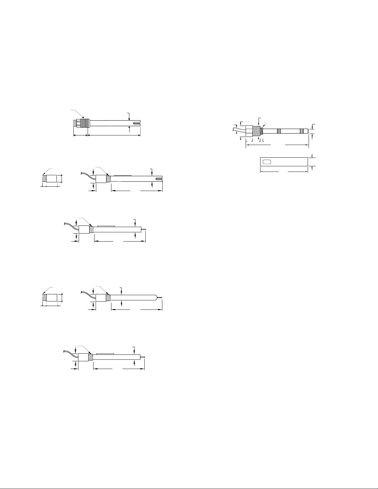
RECOMMENDED pH ELECTRODES
All electrodes are gel-filled and with ceramic junction unless otherwise
indicated.
HI 1090T Screw connector, external PG13.5 thread, double junc-
tion, glass-body
PG13.5 THREAD
φ 12mm φ9.5mm
ELECTRODE STORAGE SOLUTIONS
HI 70300M Storage solution, 230 mL
HI 70300L Storage solution, 460 mL
ELECTRODE CLEANING SOLUTIONS
HI 7061M General cleaning sol., 230 mL
HI 7061L General cleaning sol., 460 mL
HI 7073M Protein cleaning sol., 230mL
HI 7073L Protein cleaning sol., 460mL
HI 7074M Inorganic cleaning sol., 230mL
HI 7074L Inorganic cleaning sol.,460mL
HI 7077M Oil & fat cleaning sol., 230 mL
HI 7077L Oil & fat cleaning sol.,460 mL
REFILLING ELECTROLYTE SOLUTIONS
HI 7071 3.5M KCl+AgCl electrolyte, 4x50mL, for single junc-
tion electrodes
HI 7072 1M KNO3 electrolyte, 4x50 mL
HI 7082 3.5M KCl electrolyte, 4x50 mL, for double junction
electrodes
110mm30mm
HI 1110S Screw connector, single junction, glass-body
HI 1130B/3 BNC connector, 3 m (9.9') cable, single junction, glass-
body with external thread
3/4 x 16 UNF
DIA 20.5mm
38.5mm
HI 1110S HI 1130B/3
DIA 9.5mm
DIA 12mm
110mm
HI 1110T Screw connector, external PG13.5 thread, double junc-
tion, glass-body with ground glass junction
PG13.5 THREAD
φ 12mm φ9.5mm
110mm30mm
HI 1114S Screw connector, double junction plastic-body
HI 1134B/3 BNC connector, 3 m (9.9') cable, double junction
Ultem®-body with external thread
3/4 x 16 UNF
DIA 20.5mm
38.5mm
HI 1114S HI 1134B/3
DIA 12mm
110mm
HI 1115S Screw connector, single junction, refillable with side-
arm, glass-body
Ultem® is a registered Trademark of "General Electrics Company"
46
47
Page 25

M13 x 1.5
DIA
16
mm
7
mm
25
mm
HI 1135B/3 BNC connector, 3 m (9.9') cable, single junction,
M13 x 1.5
DIA
16
mm
7
mm
25
mm
refillable with side-arm, glass-body
HI 2910B/5 BNC connector, 5 m (16.5') cable, double junction,
Ultem®-body with built-in amplifier and cloth junction
3/4 x 16 UNF
DIA 20.5mm
DIA 12mm
HI 1115S HI 1135B/3
HI 1210T Screw connector, external PG13.5 thread, double junc-
tion, Ultem®-body, cloth junction
PG13.5 THREAD
φ 12mm
110mm30mm
HI 1910B BNC connector, 1 m (3.3') cable, double junction,
plastic-body with built-in amplifier and external thread
3/4 x 16 UNF
DIA 20.5mm
38.5mm
DIA 12mm
110mm
HI 1912B BNC connector, 1 m (3.3') cable, double junction,
plastic-body with built-in amplifier and external thread
HI 1912B/5 BNC connector, 5 m (16.5') cable, double junction,
plastic-body with built-in amplifier and external thread
HI 2114B/5 BNC connector, 5 m (16.5') cable, double junction,
Ultem®-body with external thread and cloth junction
3/4 x 16 UNF
DIA 20.5mm
38.5mm
DIA 12mm
110mm
38.5mm
110mm
PLATINUM ORP ELECTRODES
HI 2930B/5 BNC connector, 5 m (16.5') cable, double junction, Pt,
Ultem®-body with built-in amplifier, external thread
and cloth junction
3/4 x 16 UNF
DIA 20.5mm
38.5mm
HI 3110S Screw connector, single junction, Pt, glass-body
HI 3130B/3 BNC connector, 3 m (9.9') cable, Pt, glass-body with
external thread
3/4 x 16 UNF
DIA 20.5mm
38.5mm
HI 3110S HI 3130B/3
HI 3110T Screw connector, external PG13.5 thread, double
junction, Pt, glass-body
PG13.5 THREAD
HI 3115S Screw connector, single junction, Pt, refillable with
side-arm, glass-body
HI 3135B/3 BNC connector, 3 m (9.9') cable, single junction, Pt,
refillable with side-arm, glass-body
M13 x 1.5
DIA
16
mm
25
7
mm
mm
HI 3115S HI 3135B/3
DIA 12mm
110mm
DIA 12mm
110mm
φ 12mm φ 1mm
110mm30mm
Ultem® is a registered Trademark of "General Electrics Company"
48
Ultem® is a registered Trademark of "General Electrics Company"
49
Page 26
HI 3210T Screw connector, external PG13.5 thread, double junc-
M13 x 1.5
DIA
16
mm
7
mm
25
mm
tion, Pt, Ultem®-body
PG13.5 THREAD
φ 12mm
CONDUCTIVITY PROBE
HI 7637 Submersion 4-ring conductivity probe with automatic
temperature compensation and 3 m (10') cable
21mm
DIA
6mm
0.23"
22.5mm
0.89"
DIA
0.82"
DIA
1/2" NPT
7.7mm
0.30"
DIA
110mm30mm
HI 3410S Screw connector, double junction, Pt, Ultem
®
-body
HI 3430B/3 BNC connector, 3 m (9.9') cable, double junction, Pt,
®
-body with external thread
Ultem
3/4 x 16 UNF
DIA 20.5mm
38.5mm
HI 3410S HI 3430B/3
DIA 12mm
110mm
HI 3932B/5 BNC connector, 5 m (16.5') cable, double junction, Pt,
Ultem®-body with built-in amplifier and external thread
3/4 x 16 UNF
DIA 20.5mm
38.5mm
DIA 12mm
110mm
GOLD ORP ELECTRODES
HI 4110S Screw connector, single junction, Au, glass-body
HI 4130B/3 BNC connector, 3 m (9.9') cable, single junction, Au,
glass-body with external thread
DIA
16
mm
3/4 x 16 UNF
DIA 20.5mm
M13 x 1.5
25
7
mm
mm
HI 4110S HI 4130B/3
HI 4932B/5 BNC connector, 5 m (16.5') cable, double junction,
Au, Ultem®-body with built-in amplifier and external
thread
3/4 x 16 UNF
DIA 20.5mm
38.5mm
38.5mm
DIA 12mm
110mm
DIA 12mm
110mm
16 14x 0.75 6
125 mm
4.92"
92.5 mm
3.64"
DIA
16.5 mm
0.65"
OTHER ACCESSORIES
BL PUMPS Dosing pumps (several models are available with
flow rate from 1.5 to 18.3 lph / 0.4 to 4.8 gph)
ChecktempC Pocket-size thermometer (range -50.0 to 150.0°C)
ChecktempF Pocket-size thermometer (range -58.0 to 302.0°F)
HI 6050 Submersible electrode holder (605 mm/23.8" total
length)
HI 6051 Submersible electrode holder (1105 mm/43.5" total
length)
HI 6054B Electrode holder for in-line applications
HI 6054T Electrode holder for in-line applications (for electrodes
supplied with screw connector PG13.5 external thread)
HI 6057 3.4" nipple for in-line installations
HI 731326 Calibration screwdriver (20 pcs)
HI 7669/2W Temperature probe
HI 767/P Power plug (5 pcs)
HI 7671/P Output plug (5 pcs)
HI 779/P 6 wire cable 100m/330' long for HI 7637
HI 7871 Level controller (requires HI 7874 and HI 7875/P)
HI 7873 Level controller with alarm (requires HI 7874 and
HI 7875/P)
HI 7855/1 Screw to BNC connector with 1 m (3.3') cable
HI 7855/10 Screw to BNC connector with 10 m (33') cable
HI 7855/15 Screw to BNC connector with 15 m (49.5') cable
Ultem® is a registered Trademark of "General Electrics Company"
50
Ultem® is a registered Trademark of "General Electrics Company"
51
Page 27

HI 7855/3 Screw to BNC connector with 3 m (10') cable
HI 7855/5 Screw to BNC connector with 5 m (16.5') cable
HI 8427 pH and ORP Electrode Simulator and high imped-
ance tester with 1 m (3.3') Coaxial Cable ending in
Female BNC Connectors (HI 7858/1)
HI 8614 pH transmitter
HI 8614L pH transmitter with LCD
HI 8615 ORP transmitter
HI 8615L ORP transmitter with LCD
HI 8733 Portable ATC conductivity meter
HI 9033 Waterproof portable ATC conductivity meter
HI 931001 pH and ORP Electrode Simulator with LCD Display
and 1 m (3.3') Coaxial Cable ending in Female BNC
Connectors (HI 7858/1)
MANWMR1 Instruction Manual
WARRANTYWARRANTY
WARRANTY
WARRANTYWARRANTY
All Hanna controllers are warranted for two years against defects
in workmanship and materials when used for their intended purpose
and maintained according to instructions.
Damages due to accident, misuse, tampering or lack of prescribed
maintenance are not covered. This warranty is limited to free of
charge repair or replacement of the meter only, if any malfunctioning
is due to manufacturing defects.
If service is required, contact the dealer from whom you purchased the
instrument. If under warranty, report the model number, date of
purchase, serial number and the nature of the failure. If the repair
is not covered by the warranty, you will be notified of the charges
incurred. If the instrument is to be returned to Hanna Instruments,
first obtain a Returned Goods Authorization Number from the Customer Service department and then send it with shipment costs
prepaid. When shipping any instrument, make sure it is properly
packaged for complete protection.
To validate your warranty, fill out and return the enclosed warranty
card within 14 days from the date of purchase.
All rights are reserved. Reproduction in whole or in part is prohibited
without the written consent of the copyright owner,
Hanna Instruments Inc., 584 Park East Drive, Woonsocket,
Rhode Island, 02895 , USA.
52
Hanna Instruments reserves the right to modify the design,
construction and appearance of its products without advance
notice.
53
Page 28

OTHER PRODUCTS FROM HANNAOTHER PRODUCTS FROM HANNA
OTHER PRODUCTS FROM HANNA
OTHER PRODUCTS FROM HANNAOTHER PRODUCTS FROM HANNA
• CABLES AND CONNECTORS
• CALIBRATION AND MAINTENANCE SOLUTIONS
• CHEMICAL TEST KITS
• CHLORINE METERS
• CONDUCTIVITY/TDS METERS
• DISSOLVED OXYGEN METERS
• HYGROMETERS
• ION SPECIFIC METERS (Colorimeters)
• MAGNETIC STIRRERS
• Na/NaCl METERS
• pH/ORP/Na ELECTRODES
• pH METERS
• PROBES (DO, µS/cm, RH, T, TDS)
• PUMPS
• REAGENTS
• SOFTWARE
• THERMOMETERS
• TITRATORS
• TRANSMITTERS
• TURBIDITY METERS
• Wide Range of Accessories
CE DECLARATION OF CONFORMITYCE DECLARATION OF CONFORMITY
CE DECLARATION OF CONFORMITY
CE DECLARATION OF CONFORMITYCE DECLARATION OF CONFORMITY
Most Hanna meters are available in the following formats:
• BENCH-TOP METERS
• POCKET-SIZED METERS
• PORTABLE METERS
• PRINTING/LOGGING METERS
• PROCESS METERS (Panel and Wall-mounted)
• WATERPROOF METERS
• METERS FOR FOOD INDUSTRY
For additional information, contact your dealer or the nearest Hanna
Customer Service Center.
You can also e-mail us at tech@hannainst.com.
54
Recommendations for Users
Before using these products, make sure that they are entirely suitable for the environment in which they are used.
Operation of these instruments in residential areas could cause unacceptable interference to radio and TV equipment.
Any variation introduced by the user to the supplied equipment may degrade the
instruments' EMC performance.
Unplug the instruments from power supply before replacing the fuse or making any
electrical connections.
55
Page 29
HANNA LITERATUREHANNA LITERATURE
HANNA LITERATURE
HANNA LITERATUREHANNA LITERATURE
POOLS & SPAS WATER ANALYSIS
ENVIROCARE GENERAL CATALOG
These and many others catalogs, handbooks and leaflets are available from Hanna. To receive your free copy, contact your dealer or the
nearest Hanna Customer Service Center.
http://www.hannainst.com
PRINTED IN ITALY
MANWMR1 03/97
 Loading...