

Page 1

PL 100 / PL 101PL 100 / PL 101
PL 100 / PL 101
PL 100 / PL 101PL 100 / PL 101
Amperometric
Chlorine Titrators
Instruction Manual
Page 2

Dear Customer ,
Thank you for choosing a Hanna Product.
This instruction manual has been written for the following products:
PL 100 Free Chlorine T itrator
PL 101 T otal Chlorine T itrator
Both the instruments have features such as recorder outputs, 12VDC power supply for
safety and reduction of EMI and built-in stirrer .
Please read this instruction manual carefully before using the instrument. It will provide
you with the necessary information for the correct use of the instrument, as well as a
precise idea of its versatility .
These instruments are in compliance with directives EN 50081-1, EN 50082-1 and
EN 61010-1.
ISO 9000 Certified Company since 1992ISO 9000 Certified Company since 1992
ISO 9000 Certified Company since 1992
ISO 9000 Certified Company since 1992ISO 9000 Certified Company since 1992
2
Page 3

TABLE OF CONTENTS
PRELIMINARY EXAMINATION . . . . . . . . . . . . . . 4
GENERAL DESCRIPTION . . . . . . . . . . . . . . . . . 5
FUNCTIONAL DESCRIPTION . . . . . . . . . . . . . . 6
SPECIFICATIONS. . . . . . . . . . . . . . . . . . . . . . . 9
METHOD OF ANALYSIS. . . . . . . . . . . . . . . . . 10
Forward titration . . . . . . . . . . . . . . . . . . . 10
Back titration . . . . . . . . . . . . . . . . . . . . . 11
End Point determination . . . . . . . . . . . . . . 11
HOW TO SELECT THE CORRECT
AMPEROMETRIC TITRATION PROCEDURE . . . 13
HOW TO COLLECT THE SAMPLE . . . . . . . . . . 14
OPERATIONAL GUIDE. . . . . . . . . . . . . . . . . . 15
Initial preparation . . . . . . . . . . . . . . . . . . 15
Method A: Free Chlorine forward titration. . 15
Method B: T otal Chlorine forward titration. . 1 6
Method C: T otal Chlorine back titration . . . 1 8
INTERFERENCES AND SOURCES OF ERROR. . 2 1
MAINTENANCE . . . . . . . . . . . . . . . . . . . . . . 23
Calibration requirements . . . . . . . . . . . . . 23
Probe conditioning . . . . . . . . . . . . . . . . . 23
Electrode cleaning procedure . . . . . . . . . . 23
ACCESSORIES . . . . . . . . . . . . . . . . . . . . . . . 24
WARRANTY . . . . . . . . . . . . . . . . . . . . . . . . . 25
OTHER PRODUCTS FROM HANNA . . . . . . . . 26
CE DECLARATION OF CONFORMITY. . . . . . . 27
3
Page 4

PRELIMINARY EXAMINATION
Remove the instrument from the packing material and examine it carefully to make sure that no damage has occurred
during shipping. If there is any noticeable damage, notify
your Dealer immediately .
Each titrator is supplied complete with HI 710005 or HI
710006 12VDC power adapter .
PL 100C and PL 101C are also supplied with:
• HI 3500A-1 10mL burette
• HI 3500B reagent container
• HI 3500C rubber bulb
• 50mm (2”) long (dia. 7 mm/0.3”) magnetic stir bar
• HI 3132B glass-body platinum-platinum electrode with
1 m (3.3”) cable and BNC connector
• HI 76405 electrode holder
• small spoon
• graph paper
• recorder plug
Note Save all packing materials until you are sure that the instru-
ment functions correctly . Any damaged or defective items must
be returned in their original packing materials together with
the supplied accessories.
Safety Precautions Please take the time to read the safety precautions carefully
wherever they appear in this manual. They are provided to
prevent personal injury and damage to the instrument. This
safety information applies to the operators and service personnel and the following two captions are used:
CAUTION: identifies conditions or practices that could result in damage to the instrument or persons;
WARNING: identifies conditions or practices that could result in personal injury or loss of life.
Note Because of the inherent dangers in handling chemical
samples, standards and reagents, HANNA Instruments
strongly recommends the user of this product to review the
Material Safety Data Sheets and become familiar with safe
handling procedures and proper usage prior to handling
any chemicals.
4
Page 5

GENERAL DESCRIPTION
The Hanna PL 100 and PL 101 Chlorine Analyzers are
amperometric titrators which allow the determination of the
chlorine content in a known quantity of sample . The PL 100
measures Free Chlorine and the PL 101 T otal Chlorine.
The Hanna PL 100 and PL 101 Amperometric Titrators are
laboratory instruments containing a precision adjustable voltage source, a microammeter with LCD display , and a speed
regulated magnetic stirrer .
They operate providing a constant voltage to a dual electrode platinum probe and indicating the resulting probe
current. As titration proceeds, the change of the electrode
current is noted. At the point known as the End P oint, abrupt
change in the slope of the current curve occurs and the titration is complete. Sample concentration may be derived from
the End Point value.
The magnetic stirrer rotates at 300 RPM during the titration to
ensure proper mixing of the sample and titrant, yet slowly
enough to avoid volatilization of the measured species. The
stirrer motor is turned on and off with a rocker switch on the
front panel.
The instrument case features a stainless steel top and easy
visible LCD display for viewing the measured probe current.
Adjustment of applied probe voltage is provided by a digital
potentiometer . The potentiometer setting is controlled by two
keys in the front panel: ” ” and “ ”. A static digital memory
retains the last value set when the instrument power is re-
moved.
The PL 100 and PL 101 also feature a recorder output which
provides a low impedance output voltage from 0.00 to 2.00V :
This voltage corresponds to the probe current displayed on
the front panel LCD display . P robe current range is 0.00 to
2.00 µA.
A 10 mL glass automatic burette system is available together
with standard titration solutions 0.00564N Phenylarsine Oxide (P AO) and 0.000564N PA O, to cover the 0-1.5 ppm of
Cl2 or 1-15ppm of Cl2.
In addition to these a 0.00188N Iodine standard titration
solution is available in the range 0-4ppm of T otal Chlorine.
5
Page 6
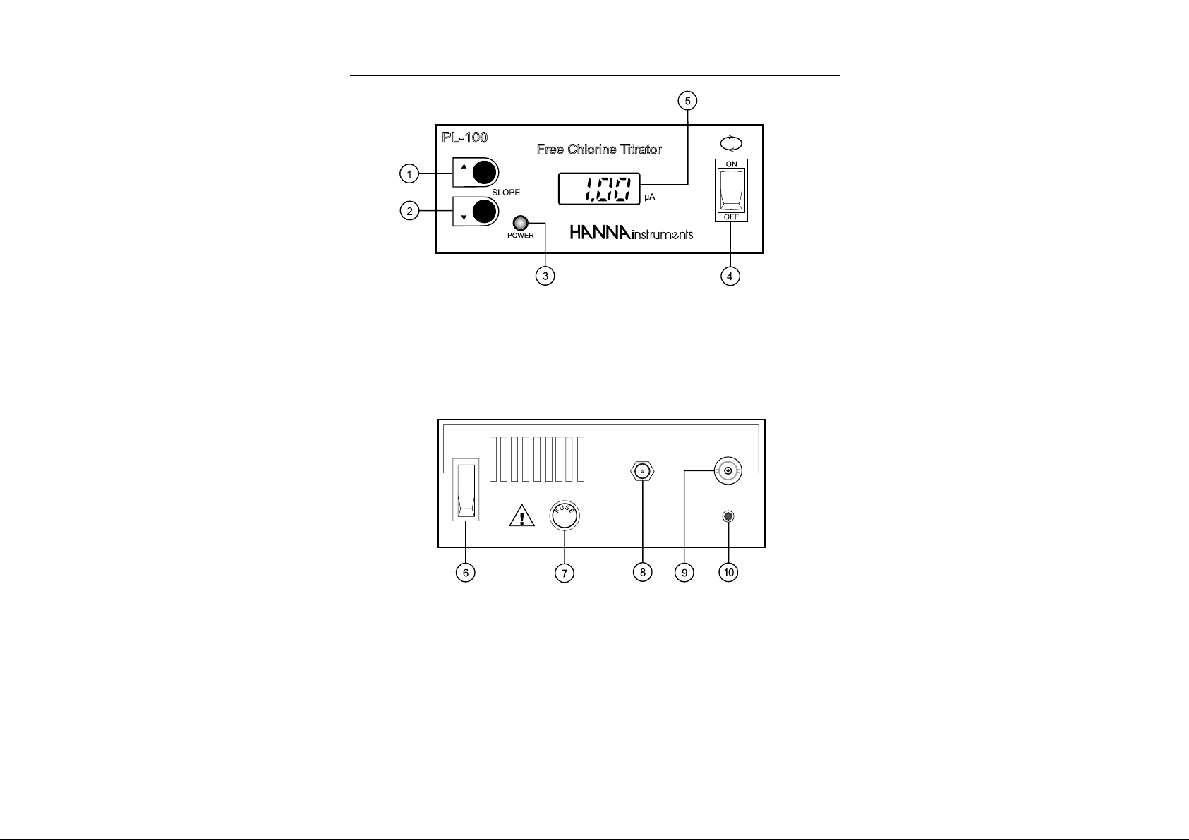
FUNCTIONAL DESCRIPTION
FRONT PANEL
1. UP key
2. DOWN key
3. Power LED
4. Stirrer ON/OFF switch
5. LCD Display
REAR PANEL
6. ON/OFF switch
7. Fuse holder
8. 12 VDC socket (for HI710005 or HI 710006)
9. BNC Electrode socket
10. Recorder output
6
Page 7

FRONT PANEL
Display
The digital redout indicates the probe current in microamps.
An overcurrent situation (greater than 1.99 µA) results in a
“1.” display (no tenths or hundredths digit). T o reduce probe
current, merely reduce probe voltage by pressing the front
panel “ ” key .
Power on indicator
During normal operation the red front panel indicator LED
should be on continuously , indicating that the instrument is
turned on.
Stirrer motor switch
This switch, located on the right hand side of the front panel,
operates the stirrer . Instrument power must be on (LED indicator on) for the stirrer to operate.
“ ” and “ ” bias control keys
Bias voltage applied to the probe is controlled by a digital
potentiometer . The potentiometer has sixty-four steps which
are selected with the front panel “ ” and “ ” keys. A single
depression causes the potentiometer setting to increase or
decrease by one step. Pressing and holding one of the keys
for one second causes the potentiometer to increment or decrement at ten steps per second until the key is released or
until the end of the taper is reached.
A static digital memory retains the last setting when the power
is turned off or removed from the system.
REAR PANEL
Power on switch
T o power on and off the instrument.
Probe input connector
The probe is connected to the rear of the instrument with a
BNC connector .
Recorder output connector
The recorder output female connector is located on the rear
panel of the instrument. The recorder connecting cable is
terminated with a male banana type plug provided with the
instrument.
7
Page 8

Recorder output
Power
Fuse
The recommended recorder hookup uses a shielded, twistedpair cable. The shield should be connected to (earth) ground
at the recorder end and left open at the instrument end.
The output is 0.00 to 2.00 V corresponding to 0.00 to 2.00
µA probe current as indicated on the front panel display .
Power is provided from the mains through a HI 710005 or HI
710006 power adapter . Be sure the mains voltage matches
the input voltage specified on the power adapter . The power
adapter output connector plugs into a socket on the back
panel of the instrument.
Caution: The power adapter may be damaged if not operated at the
correct voltage.
The instrument power conditioning circuitry is protected with
a 200 mA, 5 x 20mm tubular fuse located on the rear panel.
To replace the fuse simply twist off the fuse holder cap and
replace the fuse.
Unplug the meter before replacing the fuse.
8
Page 9

SPECIFICATIONS
Range 0 - 750mVDC probe voltage
Resolution 0.01 µA
Accuracy ±0.01 µA
Probe HI 3132B glass-body platinum
Recorder output 0.00 to 2.00V
T ypical EMC ±1% f.s.
Deviation
Stirrer Motor Speed 300 ±10 RPM (constant)
Power Source 12VDC through HI 710005 or HI 710006
Environment 0 to 50°C (32 to 122°F);
Dimensions 180x180x70mm (7.1x7.1x2.8")
PL 100 PL 101
0.00 - 2.00µA probe current
electrode with 1 m (3.3”) cable
corresponding to 0.00 to 2.00 µA
(included)
0 to 95%RH (non condensing)
Weight 1.6 Kg (3.6 lb.)
9
Page 10

METHOD OF ANALYSIS
Amperometric titration involves measuring the electrical current flow between two electrodes, usually platinum, immersed
in a known quantity of a sample solution which contains an
unknown concentration of the chemical to be measured. The
titration of the chlorine with the reducing compound
Phenylarsine Oxide (PA O) is an application of this technique.
When a small potential is applied across the two platinum
electrodes of the titrator probe immersed in the solution containing Free Chlorine, a small electrical current will flow . The
reversible reaction Cl2 + 2e- 2 Cl- occurs at both electrodes as the reducible form is oxidized at the anode and the
oxidized form is reduced at the cathode.
FORWARD TITRA TION
The gradual addition of the reductant PAO (titrant), in an
environment buffered at pH 7, irreversibly reduces the oxidized form of the Chlorine present. The reaction it undergoes
is:
PhAsO + Cl2 + 2H2O PhAsO(OH)2 + 2Cl- + 2H
(Ph =phenyl) (a)
The final removal of all oxidized Chlorine terminates the re-
versible reaction and the probe current goes to zero.
In the case of Chloramine determination, the pH is lowered
to 4 and potassium iodide is added to convert the chloramine species to an equivalent amount of triiodide.
NH2Cl + 3I- +H2O + H+ NH4OH + Cl- + I
(monochloramine).
NHCl2 + 6I- +H2O + 2H+ NH4OH + 2Cl- + 2I
(dichloroamine).
The triiodide is titrated with PAO with the current change
measured amperometrically .
PhAsO + I
By knowing the exact amount of the reductant added which
just extinguishes the probe current, the original concentration of Chlorine present in the sample may be calculated.
Required data for the calculation are: sample volume, re-
-
+ 2H2O 3I- + PhAsO(OH)2 + 2H
3
+
-
3
-
3
+
(b)
10
Page 11

ductant concentration and the activity ratio of the reductant
to the measured substance.
BACK TITRA TION
For waters which contain potential chemical interferences or
low concentration of Total Chlorine, a back -titration is recommended. In the back-titration procedure, a known excess
amount of PAO is added to the sample at pH 4 with an
excess of iodide. The PA O reacts with the free chlorine and
chloramines present. The amount of unreacted PAO is titrated with an iodine solution. A blank back-titration is also
required. The total chlorine is then calculated, based on the
P AO left in the sample.
The back amperometric End Point is signaled when free iodine (triiodide ion) is present, which is indicated by a current
flow between the electrodes (see chemical reaction (a) and
(b)).
The back-titration method is popular in wastewater laboratories because:
• the sample chlorine can be “fixed” at the sampling site
with the addition of excess reductant.
• Since the End P oint is reversed, there is less interference
from iodine-demand substances in the sample.
END POINT DETERMINATION
At the point known as the End Point, abrupt change in the
slope of the current curve occurs and the titration is complete. Typical titration plots for the forward and back
amperometric titration are shown in pictures below.
As the End Point is approached titrant has to be delivered in
small amounts, while microampere readings have to be re-
11
Page 12

corded after each addition (for best results at least 3 points
before and 3 points after the End Point). The End Point is
determined by the intersection of the two best lines through
the points. The titrant volume is multiplied by a factor to obtain the sample chlorine concentration or can be read (only
in case of forward titration) straight from the graph if the PL
100/PL 101 graph-paper is used.
12
Page 13

HOW TO SELECT THE CORRECT
AMPEROMETRIC TITRATION PROCEDURE
Select the procedure that best fits to your need as suggested
in the block diagram below .
Forward titration can be performed in two ranges:
LOW RANGE when using 0.000564N PAO
HIGH RANGE when using 0.00564N PAO
Do not perform measurements using the forward titration
method when chlorine concentration is under 0.05 mg/L.
Use back titration for low concentrations of T otal chlorine.
DRINKING AND WASTEWA TER
FREE CHLORINE
(PL 100 only)
FORWARD TITRATION
Low range
• 0-1500 µg/L (detection
limit 0.05 mg/L)
High range
• 1000-15000 µg/L
METHOD A
TOT AL CHL ORINE
(PL 101 only)
FORWARD TITRA TION
Low range
• 0-1500 µg/L (detection
limit 0.05 mg/L)
High range
• 1000-15000 µg/L
METHOD B METHOD C
BACK TITRA TION
Range
• 0-4000 µg/l
13
Page 14

HOW TO COLLECT THE SAMPLE
F ree chlorine is a strong oxidizing agent and in natural waters reacts with various inorganic and organic compounds,
its decomposition being influenced by parameters like reactant concentrations, pH, temperature, salinity and sunlight.
Combined chlorine (chloroamines) is more stable and persistent in the environment.
For best results, the delay between sample collection and
analysis should be minimized.
Plastic sample containers have a high chlorine demand, thus
collect sample in glass bottles. If possible rinse the container
with a portion of the sample otherwise rinse with deionized
water.
Fill the bottle up to the rim and keep it tightly closed.
Avoid excess agitation and exposure to sunlight when sam-
pling.
If the back titration method is used for total chlorine determi-
nation, preserve the sample on site. Add 2.00 mL of 0.00564N
standard PAO solution and 1.0 mL pH 4 Acetate Buffer to a
clean dry glass container with at least 150 mL capacity. At
the sampling site, measure 100 mL of sample and carefully
transfer it to the sample container . Swirl to mix.
It is important that the entire contents of the sample container
be transferred to the beaker used in the titration. Rinse the
bottle a few times with a small amount of chlorine free water .
14
Page 15

OPERATIONAL GUIDE
INITIAL PREPARA TION
• Connect the power supply adapter to the DC input
• Connect the probe to the BNC connector .
• Be sure the front stirring switch is
in the OFF position and turn the
instrument on by the ON/OFF
switch on the rear panel.
PROCEDURES
Method A: free chlorine forward titration (PL100 only)
1. Fill the bottle of the automatic burette with
0.000564N P AO solution (HI 70471) for
titrations up to 1500 µg/L Cl2 or use the
0.00564N PA O solution (HI 70470) for
titrations up to 15000 µg/L Cl2. Fill the
10 mL automatic burette to the zero mark.
2. Use a 100 mL volumetric pipet to transfer 100 mL of sample to a 250 mL beaker
and add about 100 mL chlorine free water.
3. Place the stirbar into the beaker .
4. Add 1 mL of pH 7 phosphate buffer solution (HI 70472) to the beaker .
Note: If the pH of the sample is between 6.0 and 7.5
it is not necessary to add the buffer .
5. Turn on the speed controlled stirrer and
place the beaker on the top of the PL 100.
6. Immerse the probe tip into the sample, make
sure the platinum electrodes are submerged.
7. Adjust the potentiometric setting, using the “ ”
and “ ” keys on the front panel until the dis-
play reads about 1.00.
15
Page 16

8. Dispense the titrant into the beaker in
small increments. Note the downward
reading on the amperometric titrator.
Record the display reading that corresponds exactly to the mL of the titrant
added. Record at least 3 points before and
3 points after the End P oint.
9. Construct a titration graph using the PL 100 graph paper .
10.Draw the best-fit line
through each set of
points. The end
point is determined
by the intersection of
the two best lines
through the points.
11 .Read directly the free chlorine concentration on the
top of the graph by drawing a straight vertical line through
the End Point or read the volume of titrant used until the
End Point and multiply by 2 when titrant (a) 0.00564N
PA O is used or multiply by 0.2 when titrant (b) 0.000564N
P AO is used.
mL
(till End Point)
x 2
= mg/L Free Cl2.
(or 0.2)
Method B: Total Chlorine Forward Titration (PL 101 only)
1. Fill the bottle of the automatic burette with
0.000564N PAO solution (HI 70471)
for titrations up to 1500µg/L Cl2 or use
the 0.00564N PA O solution (HI 70466)
for titrations up to 15000µg/L Cl2. Fill the
10 mL automatic burette to the zero mark.
2. Use a 100 mL volumetric pipet to transfer 100mL of sample
to a 250 mL beaker and add about 100 mL chlorine free
water.
3. Add one spoon of potassium iodide from the bottle (HI
70468) and swirl to dissolve. Place the stirbar into the
beaker.
4. Add 1 mL of pH 4 acetate buffer solution
(HI 70467) into the beaker .
5. Turn on the speed controlled stirrer and
place the beaker on the top of the PL 101.
16
Page 17

6. Immerse the probe tip into the sample,
make sure the platinum electrodes are
submerged.
7. Adjust the potentiometric setting, using the “ ” and “ ” keys on the front
panel until the display reads about 1.00.
8. Dispense the titrant into the beaker in
small increments. Note the downward
reading on the amperometric titrator.
Record the display reading that corresponds exactly to the mL of titrant
added. Record at least 3 points before
and 3 points after the End P oint.
10.Construct a titration graph using the
PL 101 graph-paper .
11 .Draw the best-fit line through each set of points. The End
Point is determined by the intersection of the two best lines
through the points.
12 . Read directly the total chlorine concentration on the top
of the graph by drawing a straight vertical line through the
End Point or read the volume of titrant used until the End
Point and multiply by 2 when titrant (a) 0.00564N P A O is
used or multiply by 0.2 when titrant (b) 0.000564N P AO
is used.
mL
(till End Point)
x 2
= mg/L Total Cl2.
(or 0.2)
17
Page 18

Method C: Total Chlorine back titration (PL 101 only)
Instrument setting
1. Fill the bottle of the automatic burette with
0.00188N I2 solution (HI 70469) and fill
the 10 ml automatic burette to the zero mark.
2. Place the stirbar into a clean 250 mL beaker
and add about 200 mL deionized water .
3. Add 1 mL of pH 4 acetate buffer (HI
70467) and one spoon of potassium iodide from the bottle (HI 70468).
4. Turn on the speed controlled stirrer and
place the beaker on the top of the PL 101.
5. Immerse the probe tip into the solution, make
sure the platinum electrodes are submerged.
6. Add 1.5 mL of the iodine solution into the beaker and adjust the potentiometric setting using
the ” ” and “ ” keys on the front panel until the
display reads about 0.50 -0.70. Switch off the
stirring action.
7. Remove the probe from the beaker and rinse the platinum electrodes with deionized water . The probe response
slope is adjusted. Don’t change the setting from this point.
18
Blank Titration
8. Refill the automatic burette to the zero mark.
9. Place the stirbar into a clean 250 mL beaker and add
about 200 mL of deionized water .
10. Add exactly 2.00 mL of the standard 0.00564N PAO
solution (HI 70466) to the beaker and swirl to mix.
11. Add 1 mL of pH 4 acetate buffer solution (HI 70467) and
one spoon of potassium iodide from the bottle (HI 70468)
12. Turn on the speed controlled stirrer and
place the beaker on the top of the PL 101.
Page 19

13.Immerse the probe tip into the sample
and make sure the platinum electrodes
are submerged.
14. Dispense 5 mL of titrant into the beaker.
15.Continue dispensing titrant into the
beaker in small increments. Record the
display reading that corresponds exactly
to the mL of titrant added. Record at
least 3 points before and 3 points after
the End P oint.
16. Construct a titration graph.
17 .Draw a best-fit line through each set of points. The End
Point is determined
by the intersection of
the two best lines
through the points.
18. Read the volume
of titrant used until
the End Point, this is
mL zero.
Note: Standard Iodine is subjected to a normal degradation and
this could lead to an increasing of the End P oint under the
same measurement conditions. Blank titration compensates
for standard iodine degradation. Discard a standard iodine
solution if the End P oint is grater than 8 mL and repeat the
procedure with new standard iodine.
Sample titration
19 .Refill the automatic burette to the zero mark.
20. Use a 100 mL volumetric pipet to transfer 100 mL of
sample to a 250 mL beaker and add about 100 mL chlorine free water .
21 .Add exactly 2 mL of the standard 0.00564N P A O solu-
tion (HI 70466) to the beaker and swirl to mix. Add 1 mL
of pH 4 acetate buffer (HI 70467) and one spoon of
potassium iodide from the bottle (HI 70468).
19
Page 20

Note: If the sample is pretreated at the sampling site with the PAO
and the acetate buffer as described before, transfer the sample
quantitatively to the beaker and add one spoon of potassium
iodide from the bottle (HI 70468)
22. T urn on the speed controlled stirrer and
place the beaker on the top of the PL 101.
23.Immerse the probe tip into the sample,
make sure the platinum electrodes are submerged.
24 .Dispense the titrant into the beaker in
small increments. Note the reading that
corresponds exactly to the mL of titrant
added. Record at least 3 points before
and 3 points after the End Point.
25 .Construct a titration graph.
26 .Draw a best-fit line through each set of points. The End
Point is determined
by the intersection of
the two best lines
through the points.
27. Read the volume of
titrant used until the
End Point. This is mL
sample.
28 .Calculate the total chlorine concentration using the for-
mula:
4.00 - 4.00 x (mL sample)/(mL zero) = mg/L T otal Cl2.
Note: If a negative value is found, the sample contains an excess of
de-chlorinating agent, such as sulfur dioxide, sulfite or
bisulfite.
20
Page 21

INTERFERENCES AND SOURCES OF ERRORS
Despite Standard Methods section 4500 Cl-A.3.b. states that
“the amperometric method is the method of choice because
it is not subject to interferences from color, turbidity, iron,
manganese, or nitrite nitrogen ”, the amperometric method
will detect (as all of the common chlorine methods) disinfectants such as bromine (Br2), Ozone (O3), Chlorine dioxide
(ClO2), and hydrogen peroxide (H2O2).
In general all oxidants which can be reduced by the strong
reducing agent P AO will interfere with the free chlorine determination. For the total chlorine determination, interference
can be caused by compounds that oxidize iodide to iodine
and those that can be reduced by PA O. For example, manganese in the lower oxidation states +2, +3, or +4 can be
oxidized by the free chlorine. The oxidized formes of manganese (+4 to +7) can be reduced by PAO in free chlorine
titration or manganese (+4 or +7) can oxidize iodide to
iodine during the total chlorine titration.
Hanna Instruments researchers found that nitrite interference
can cause either a positive or negative interference depending on the order of reagent addition.
Therefore the preferred procedure in the back titration for
T otal Chlorine determination is buffering the solution to pH 4
before adding KI in order to minimize nitrite, manganese and
iron interference.
For both free and total chlorine determination, Hanna instruments has selected PAO as reducing agent because it
gives a sharper end point.
The potassium iodide used for the total chlorine determination can be oxidized with enough exposure to oxygen and
ultraviolet light. Therefore keep the bottle of HI 70468 tightly
closed and out of direct sunlight. Another possible error during total chlorine determination is volatilization of free iodine.
Volatilization from the reaction mixture during the forward
titration is minimized because excess iodide is present, but
after adding the potassium iodide, start the titration as soon
as possible. Keep the standard iodine solution in a closed,
dark bottle to avoid volatilization of iodine.
21
Page 22

Iodine demand of certain samples can cause a shift of the
end point as shown in the following graph:
The iodine, formed in case of forward total chlorine determination or added as titrant during the backward titration, can
be absorbed by suspended particles or can react with organic matter . This type of interference is common in the case
of muddy or highly organic-rich samples.
Another source of error is due to the tendency of some metal
to poison the electrodes of the titrator. Iron, copper, silver
and some other species can plate or coat the platinum probe
electrodes and diminish the probe response. Therefore the
dual platinum electrode (DPE) has to be cleaned regularly
(see electrode cleaning procedure on page 23).
22
Page 23

MAINTENANCE
CALIBRATION REQUIREMENT
Calibration of the PL 100 and PL 101 Chlorine Titrators is
not required.
If, for any reason, the measurements are inaccurate, contact
your dealer or the nearest Hanna Customer Service Center
for recalibration.
PROBE CONDITIONING
When the probe has not been used for some time (one week)
or it is new , it is recommended that it be conditioned as follows:
1. Add a few drops of bleach to tap water in a 250 mL
beaker and place the stir bar in the beaker .
2. Place the beaker on the PL 100/PL 101, turn on the
instrument and the stir motor .
3. Immerse the probe in the solution, adjust the digital potentiometer for a current of 0.5 to 1.5 µA, and leave for
ten minutes.
PROBE CLEANING PROCEDURE
Cleaning involves soaking the probe in a 1:1 nitric acid solution for two hours and than rinsing with deionized water. To
stabilize the cleaned probe soak it in chlorinated tap water .
23
Page 24

ACCESSORIES
HI 3132B Glass-body platinum-platinum electrode with 1 m (3.3”) cable
and BNC connector
HI 3500A-1 10mL glass burette
HI 3500B Reagent container
HI 3500C Rubber bulb
HI 70466 PA O Standard solution 0.00564N (for PL 101 only)
HI 70467 Acetate buffer
HI 70468 Potassium iodide
HI 70469 Iodine standard solution
HI 70470 PA O Standard solution 0.00564N (for PL 100 only)
HI 70471 PA O Standard solution 0.000564N
HI 70472 Phosphate buffer
HI 710005 115 VAC to 12 VDC power adapter
HI 710006 230VAC to 12 VDC power adapter
HI 731320 50mm (2”) long, dia. 7 mm(0.3”) magnetic stirbar (10 pcs)
HI 76405 Electrode holder .
24
Page 25

WARRANTY
All Hanna Instruments meters are guaranteed for two
years against defects in workmanship and materials when
used for their intended purpose and maintained according to instructions. The electrodes and the probes are
guaranteed for a period of six months. This warranty is
limited to repair or replacement free of charge.
Damage due to accident, misuse, tampering or lack of prescribed maintenance are not covered.
If service is required, contact the dealer from whom you purchased the instrument. If under warranty , report the model
number , date of purchase, serial number and the nature of
the failure. If the repair is not covered by the warranty , you
will be notified of the charges incurred. If the instrument is to
be returned to Hanna Instruments, first obtain a Returned
Goods Authorization number from the Customer Service department and then send it with shipping costs prepaid. When
shipping any instrument, make sure it is properly packaged
for complete protection.
To validate your warranty, fill out and return the enclosed
warranty card within 14 days from the date of purchase.
Hanna Instruments reserves the right to modify the design,
construction and appearance of its products without advance
notice.
25
Page 26

OTHER PRODUCTS FROM HANNA
• CALIBRATION AND MAINTENANCE SOLUTIONS
• CHEMICAL TEST KITS
• CHLORINE METERS
• CONDUCTIVITY/TDS METERS
• DISSOLVED O XYGEN METERS
• HYGROMETERS
• ION SPECIFIC METERS (Colorimeters)
• MAGNETIC STIRRERS
• Na/NaCl METERS
• pH/ORP/Na ELECTRODES
• pH METERS
• PROBES (DO, µS/cm, RH , T , TDS)
• PUMPS
• REAGENTS
• SOFTWARE
• THERMOMETERS
• TRANSMITTERS
• TURBIDITY METERS
• Wide Range of Accessories
26
Most Hanna meters are available in the following formats:
• BENCH- T OP METERS
• POCKET -SIZED METERS
• PORT ABLE METERS
• PRINTING/LOGGING METERS
• PROCESS METERS (Panel and W all-mounted)
• WATERPROOF METERS
• METERS FOR FOOD INDUSTRY
For additional information, contact your dealer or the nearest Hanna Customer Service Center .
Y ou can also e-mail us at tech@hannainst.com.
Page 27

CE DECLARATION OF CONFORMITY
Recommendations for Users
Before using these products, make sure that they are entirely suitable for the environment in which they are
used.
Operation of these instruments in residential areas could cause unacceptable interference to radio and TV
equipment.
The metal band at the end of the sensor is sensitive to electrostatic discharges. Avoid touching this metal
band at all times.
Any variation introduced by the user to the supplied equipment may degrade the instruments' EMC
performance.
Unplug the instruments from power supply before opening the front cover.
27
Page 28

HANNA LITERATURE
Lab Recording Water Analysis Handbook
PRINTED IN PORTUGAL
Envirocare General Catalog
These and many others catalogs, handbooks and leaflets are available from Hanna. To receive your free
copy, contact your dealer or the nearest Hanna Customer Service Center.
http://www.hannainst.com
MANPL100R1
07/98
 Loading...