

Page 1
Instruction Manual
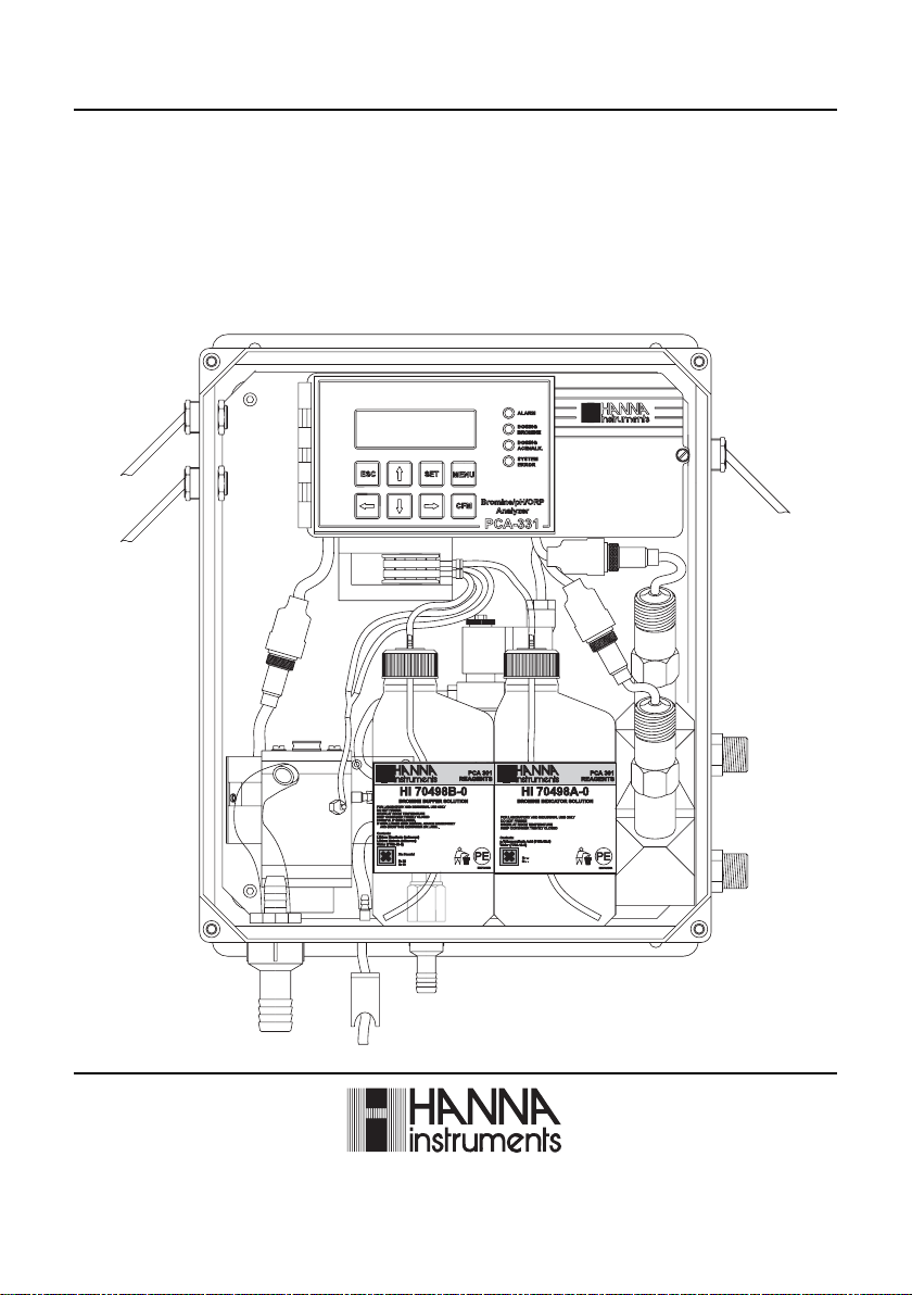
PCA 311, PCA 321, PCA 331
Bromine, pH, Temperature, ORP
Analyzers
www.hannainst.com
1
Page 2

Dear Customer,
Thank you for choosing a Hanna Product.
This instruction manual has been written for the following:
PCA 331 – Bromine, pH, temperature, ORP analyzer.
PCA 321 – Bromine, pH, temperature analyzer.
PCA 311 – Bromine analyzer.
The analyzers have features such as: automatic bromine measurement, pH, temperature
and ORP measurement, bromine and pH dosing regulator, selectable sampling
periods, alarm system, data link through GSM network, user friendly interface,
serial communication through RS485, recorder output, 4-20mA dosing output,
Nema 4X enclosure.
The ordering code for bromine analyzers is:
PCA 3a1-b
a = 1 - Bromine analyzer
2 - Bromine, pH and Temperature analyzer
3 - Bromine, pH, Temperature and ORP analyzer
b = 1 - 115V AC 50-60Hz
2 - 220V AC 50-60Hz
Please read this instruction manual carefully before using the instrument. It will provide
you the necessary information for the correct use of the instrument, as well as a
more precise idea of its versatility.
Hanna Instruments reserves the right to modify the design, construction and appearance
of its products without advance notice.
2
Page 3

TABLE OF CONTENTS
PRELIMINARY EXAMINATION........................................6
GENERAL DESCRIPTION..............................................7
MECHANICAL DIMENSIONS........................................9
FUNCTIONAL DESCRIPTION........................................10
DISPLAY, LEDS AND KEYBOARD...................................11
SPECIFICATIONS.......................................................14
OPERATING DESCRIPTION.........................................16
Bromine measurement ......................................16
Method of analysis ........................................17
pH and temperature measurement ...................17
ORP measurement ........................................17
INITIAL PREPARATION AND INSTALLATION...................18
Installation Personnel......................................18
Location of the Instrument...............................18
Hydraulic Connections....................................18
Installing the Input Filter...................................19
Installing the pH and ORP probes .....................20
Installing the Pump Tubes.................................21
Electrical Connections.....................................22
STARTUP.....................................................................26
USER INTERFACE .......................................................27
Panels organization ........................................ 27
Main panels ............................................... 27
Measure panels ............................................. 28
Messages .................................................... 29
Menu mode ................................................ 29
Password procedure ..................................... 29
Navigating through menu .............................. 30
Modify a parameter ........................................ 30
PROGRAMMING THE ANALYZER .............................. 32
GENERAL SETTINGS ...............................................33
3
Page 4

Changing the password ................................. 33
Setting the language ..................................... 33
Analyzer serial number and software version ...... 33
Time and date ............................................. 33
WORKING MODE ................................................... 34
Automatic mode .......................................... 34
Standby mode ............................................. 34
Manual mode ............................................. 34
Read on demand ........................................... 35
Direct read ................................................. 35
System error relay..............................................35
BROMINE SETTINGS ............................................... 36
Reagent changing .......................................... 36
Measure settings .......................................... 37
Measure info ................................................ 37
Analog output ............................................. 37
Bromine dosing ........................................... 38
Alarms ........................................................ 39
CALIBRATE THE MEASURING CELL ............................. 40
Calibration date and factor ............................ 40
Calibration procedure ..................................... 40
pH SETTINGS (PCA 321, PCA 331) ............................. 41
Measure info............................................... 41
Analog output ............................................. 42
pH dosing .................................................. 42
Alarms ....................................................... 44
pH CALIBRATION (PCA 321, PCA 331) ....................... 44
One point calibration ................................... 45
Two-points calibration ..................................... 46
Process pH calibration .................................... 46
Set default calibration ..................................... 47
TEMPERATURE SETTINGS (PCA 321, PCA 331) ............ 48
Units ......................................................... 48
Measure info .............................................. 48
4
Page 5

Analog output............................................. 48
Alarms ....................................................... 49
ORP SETTINGS (PCA 331) ..........................................50
Measure info .............................................. 50
Analog output ............................................ 50
Alarms ....................................................... 51
ANALOG OUTPUT .................................................. 52
Select the analog output type .......................... 52
Dosing through 4-20 mA output ...................... 52
CALIBRATE THE ANALOG OUTPUT .............................53
Output middle range ........................................54
SYSTEM LOG ..........................................................55
Set log ....................................................... 55
Clear system log .......................................... 55
View log ..................................................... 55
SERIAL COMMUNICATION ........................................ 57
Standard mode ............................................ 57
GSM ..................................................................... 58
GSM mode ................................................ 58
Setting the GSM feature ................................. 58
GSM connection .......................................... 59
Setting SMS feature ......................................... 60
Modem connection.......................................... 64
MAINTENANCE ...................................................... 65
Electrode conditioning and maintenance ........... 66
Changing peristaltic pump tubing .................... 68
Tubing replacement.......................................... 69
Cleaning measurement cell .............................. 69
Cell Cleaning Procedure ................................ 70
ERRORS, ALARMS AND WARNINGS ............................ 71
ACCESORIES ........................................................... 74
5
Page 6

PRELIMINARY EXAMINATION
Remove the analyzer from the packing material and examine
it carefully to make sure that no damage has occurred during
shipping. If there is any noticeable damage, notify your dealer
immediately.
Each analyzer is supplied complete with:
• 2 reagent bottles (1 indicator and 1 buffer solution)
• 2 reagent bottle caps
• 1 DPD compound powder
• tubing
Note: Save all packing materials until you are sure that the
instrument functions correctly. Any damaged or defective items
must be returned in their original packing materials together
with the supplied accessories.
WARNING: The PCA 311 - PCA 331 series of Bromine, pH and ORP
Analyzers are not designed for use with samples that are
inflammable or explosive in nature. If any sample solution
other than water is used with these products, test the sample/
product compatibility to assure user safety and proper product
performance.
Safety Precautions: Please take the time to read the safety precautions
carefully wherever they appear in this manual. They are
provided to prevent personal injury and damage to the
instrument. This safety information applies to the operators
and service personnel and the following two captions are
used:
CAUTION: identifies conditions or practices that could result in
damage to the instrument or persons;
Warning: identifies conditions or practices that could result in personal
injury or loss of life.
Note: Because of the inherent dangers in handling chemical
samples, standards and reagents, HANNA Instruments
strongly recommends the users of this product to review the
Material Safety Data Sheets and become familiar with safe
handling procedures and proper usage prior to handling
any chemicals.
6
Page 7
GENERAL DESCRIPTION
The Hanna PCA 311, PCA 321 and PCA 331 series of
bromine, pH, ORP and temperature analyzers are microprocessor controlled, process analyzers which continuously
monitor a sample stream for bromine content, pH, ORP
and temperature values.
The PCA 311-331 monitor the bromine in the 0.0 to 10.0 mg/L
range depending on the factory settings and used reagents.
In the DPD Colorimetric method, N, N-Diethyl-p-phenylenediamine indicator and a buffer are mixed with the sample.
The resulting chemical reaction causes a magenta color to
form. The color intensity is proportional to the concentration
of bromine. The color intensity is measured photometrically
(with a light beam and a photodetector) and converted to
bromine concentration, in mg/L, which is displayed on the
front panel.
Indicator and buffer reagent bottles are placed directly into
the instrument case. With a sampling period of 5 minutes,
reagents need to be replenished about once a month. The
reagent bottles are easily visible through the transparent
window allowing the operator to check the reagent levels.
PCA 321 and PCA 331 analyzers use a HI 1005 probe to
continuously measure the pH of the sample stream in the range
of 0 to 14 pH. The sample temperature is measured in the 5 to
75°C range. pH and temperature are displayed on the front
panel. pH value is corrected with temperature.
PCA 331 analyzer use HI 2008 platinum ORP electrode to
continuously measure the sample ORP value.
The pH/temperature combined sensor and the ORP sensor
are placed inside the case, directly in the sample stream.
The case of PCA 311-331 analyzers meet NEMA 4X, 12 and
7
Page 8

13 standards. Molded fiberglass polyester has outstanding
chemical and temperature resistance.
The case provides wall mounting capability and door gasket
assures a watertight and dust-tight seal.
The electrical and hydraulic connections are made through
the side of the enclosure.
The front cover is secured with two lockable latches.
Four bromine level setpoints can be adjusted by the operator:
a proportional dosing setpoint, two alarm setpoints and a
minimum level for dosing.
The proportional dosing factor (1/delta) is user selectable with
a delta between 0.2 and 10.0 mg/L (ppm). Bromine dosing
system controls a SPST relay.
Each bromine alarm can be enabled or disabled.
Three pH level setpoints can be adjusted by the operator: a
dosing setpoint and two alarm setpoints. The pH control mode
is user selectable: on/off or proportional dosing.
The proportional dosing factor (1/delta) is user selectable with
a delta between 0.1 and 2 pH . The on/off dosing hysteresis is
user selectable between 0.05 and 2.00 pH. pH dosing system
controls a SPST relay.
Each pH alarm can be enabled or disabled.
For temperature and ORP, two alarm levels can be set by the
user.
Each temperature or ORP alarm can be enabled or disabled.
Alarm condition controls a SPDT relay.
A system error feature provides relay activation to signals need
for operator intervention.
System error condition controls a SPST relay.
Voltage output ranges of 0-10mV, 0-100mV, 0-1V or a
current output of 4-20 or 0-20 mA are available to drive an
external device such as a chart recorder.
The analyzer can drive a proportional dosing pump through
the 4-20 mA output, for bromine or for acid/alkali dosing.
The analog output is fully programmable and could be
proportional with bromine concentration, pH, ORP or
temperature value. The limits of the analog output is
selectable for each parameter.
8
Page 9
The analyzer can store up to 3500 readings (at least 7 days at
254
304.8
338.3
389.1
374.8
254
393.7
367.1
209.8
83.1
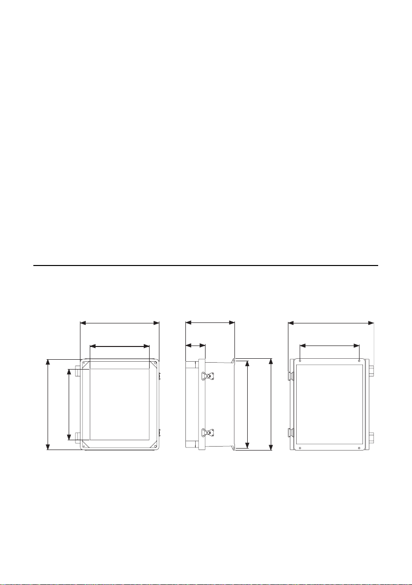
13.32"
10"
12"
15.32"
3.27"
8.26"
14.76"
15.5"
10"
14.45"
FRONT VIEW
SIDE VIEW
REAR VIEW
3 minutes sampling interval), that are available for consulting
or downloading.
The PCA 311-331 analyzers can be monitored or controlled
through RS485 or GSM network connection.
Errors, alarms and warnings are sent through SMS (using GSM
module HI 504900).
The analyzer state can be interrogated by a simple call using
GSM phone.
Time is displayed on the main panel and a time related
warning system for “Old calibration” “Reagent expired” and
“SIM expired” is available.
The language for user interface can be easily changed without
restarting the analyzer.
MECHANICAL DIMENSIONS
FRONT VIEW
SIDE VIEW
Case dimensions in mm & inches
REAR VIEW
9
Page 10
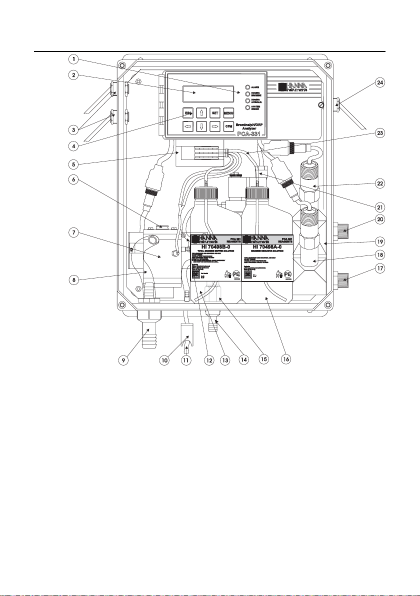
FUNCTIONAL DESCRIPTION
10
1. Alarms, dosing, system error LED’s
2. Character Display
3. Cable glands
4. Keypad
5. Peristaltic Pump
6. Access Point to Cell
7. Measuring Cell
8. Drain Tube
9. Output Port
10. Drain Port Valve
11. Drain Port of Measuring Cell
12. Sample Tubing
13. Buffer Bottle
14. Pressure Regulator Output Port
15. Incoming Pressure Regulator
16. Indicator Bottle
17. Sample Inlet Port
18. pH Electrode (not included)
19. Electrodes Holder
20. Sample Output Port
21. Electrovalve
22. ORP Electrode (not included)
23. Reagent Tubing
24. Line Input
Page 11
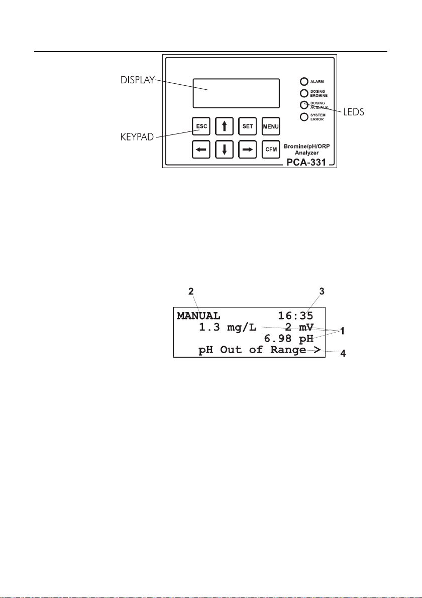
DISPLAY, LEDS AND KEYBOARD
DISPLAY
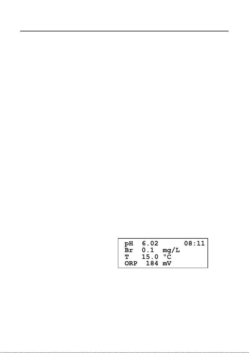
The display contains 4 lines with 20 characters on one line.
The information and error messages are clearly displayed in
plain language, without error codes.
The display has backlight for better visibility.
The analyzer is in main panels mode when displays a panel
that contains the measured values. Several main panels could
be selected by pressing the up and down arrow keys. The PCA
311 do not have the main mode for the display.
1 - measured values
2 - controller status
3 - current time and date
4 - message line
The display is in bromine, pH, ORP or temperature measuring
panels mode when displays one of those values and secondary
information related to it. Several panels with different secondary
information could be selected by pressing the up or down
arrow keys.
When the display is in one of the above modes, the measuring
units, the current time and the alarm or error status are also
displayed. PCA 311 is always in bromine measuring panels.
11
Page 12
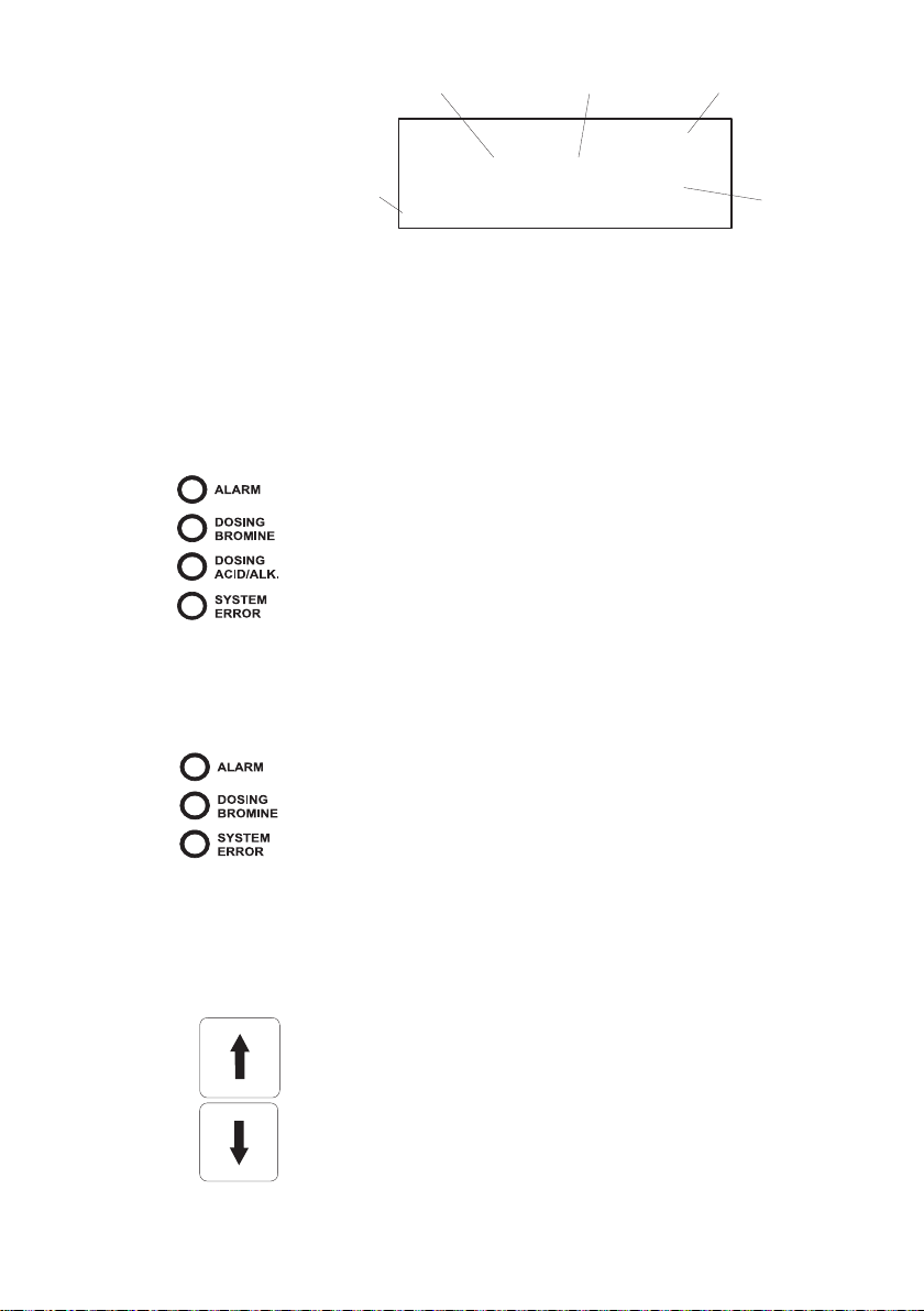
LEDs
KEYPAD
12
3
16:35
1.3 mg/L Alarm
<Br Calibration Old>
5
Min:0.0 Max:5.6
1 - measured value (bromine, pH, ORP or temperature)
2 - measurement units (mg/L, pH, mV, °C or °F)
3 - current time in format HH:MM
4 - warnings, alarms and errors, displayed one at a time
5 - secondary information.
Three or four LEDs are present on the front panel:
ALARM LED (red), signals the presence of at least one alarm
and the closing of the Alarm relay. When the alarm is
present, the LED blinks. When the analyzer is in
MANUAL mode, the LED is on but not blinking.
DOSING BROMINE LED (green), signals the closing of the
bromine dosing relay. When dosing stops, the LED is
turned off.
DOSING ACID/ALK. LED (green), signals the closing of the
acid/alkali dosing relay. When dosing stops, the LED
is turned off (PCA 321 and PCA 331 only).
SYSTEM ERROR LED (red), signals the presence of an error
and the closing of the System error relay. When the
error is present, the LED blinks. When in STANDBY
mode, the led is on but not blinking.
For PCA 311 the system error LED is moved in the dosing
ACID/ALK. LED position.
The keypad has 8 keys with the following signification:
4
12
UP and DOWN ARROWS
• select the main display appearance,
• select the menu,
• select an item from a list,
• edit values.
Page 13

LEFT and RIGHT ARROWS
• select an error message,
• select an item to edit or
• select the current digit for editing.
MENU
CFM
SET
ESC
MENU enter in menu mode.
CFM confirm the selected menu and edited values.
SET starts editing the selected item.
ESC
• return to the previous menu,
• exit from operation without saving.
13
Page 14

SPECIFICATIONS
R
R
A
T
C
M
S
D
D
R
R
A
T
C
D
D t
D
H
R
R
A
T
)sledomllA(GNISODDNATNEMERUSAEMENIMORB)sledomllA(GNISODDNATNEMERUSAEMENIMORB
)sledomllA(GNISODDNATNEMERUSAEMENIMORB)sledomllA(GNISODDNATNEMERUSAEMENIMORB
USAEMENIMORB
)sledomllA(GNISODDNATNEMER
egna
noitulose
ycarucc
noitarbila
etargnilpma
egaso
atle
egna
noitulose
ycarucc
noitarbila
etargniso
egaso
atle
siseretsy
egna
noitulose
noitaivedCMElacipy
levelelbatcetedmumini
noitaivedCMElacipy
L/gm1.0
tniop1
L/gm1.0
NATNEMERUSAEMHp
Hp10.0
Hp2.0±
Vm1
L/gm0.01ot0.0
L/gm1.0±
setunim09ot3
L/gm0.4ot2.0elbatceles
Hp00.41ot00.0
Hp50.0±
noitarbilacenilnirostniop2;1
sdnoces021ot3
Hp2ot1.0elbatceles
Hp2ot50.0elbatceles
)133ACP(TNEMERUSAEMPRO)133ACP(TNEMERUSAEMPRO
)133ACP(TNEMERUSAEMPRO)133ACP(TNEMERUSAEMPRO
)133ACP(TNEMERUSAEMPRO
Vm0002ot0
retaergsirevehcihwL/gm1.0±ro%8±
tuptuoAm02-4royalerlanoitroporP
)133ACPdna123ACP(GNISODDNATNEMERUSAEMHp)133ACPdna123ACP(GNISODDNATNEMERUSAEMHp
)133ACPdna123ACP(GNISODDNATNEMERUSAEMHp)133ACPdna123ACP(GNISODDNATNEMERUSAEMHp
)133ACPdna123ACP(GNISODD
uptuoAm02-4royaler,lanoitroporproffO/nO
ycarucc
noitaivedCMElacipy
Vm1±
Vm01±
14
Page 15

)133ACPdna123ACP(TNEMERUSAEMERUTAREPMET)133ACPdna123ACP(TNEMERUSAEMERUTAREPMET
R
R
A
T
R
S
B
D
L
L
G
A
D
S
S
S
S
S
S
D
P
P
P
C
)133ACPdna123ACP(TNEMERUSAEMERUTAREPMET)133ACPdna123ACP(TNEMERUSAEMERUTAREPMET
)133ACPdna123ACP(TNEMERUSAEMERUTAREPMET
egna
noitulose
ycarucc
noitaivedCMElacipy
tuptuoredroce
noitacinummoclaire
etardua
yalpsi
segaugna
go
mralaMS
yalermral
syalergniso
yalerrorremetsy
erusserptelnielpma
etarwolfelpma
erutarepmetelpma
telnielpma
teltuoelpma
noitcennocniar
eborppmet/Hpssecor
eborpPROssecor
stnemeriuqerrewo
esa
C°1.0
C°5.0±
C°5.0±
sdrocergol0053
V032A5TDPS
V032A5TSPS
V032A5TSPS
rab4ot70.0
nim/Lm003ot001
Cº04ot5
brab)"8/3(mm01
5001IH
8002IH
AV02
X4-AMEN
)F°761ot14(C°0.57ot0.5
)sledomllA(SREHTO)sledomllA(SREHTO
)sledomllA(SREHTO)sledomllA(SREHTO
)sledomllA(SREHTO
Am02-0,Am02-4,V1-0,Vm001-0,Vm01-0
detarapescinavlag,584SR
spb0069;0084;0042;0021
sretcarahc02xsenil4DCLretcarahc
eseugutroP,hsinapS,nailatI,hsilgnE
SMSgninraw,SMSofni,SMSmrala,srebmun2
gnittifTPNelam)"2/1(mm21
gnittifTPNelam)"2/1(mm21
15
Page 16

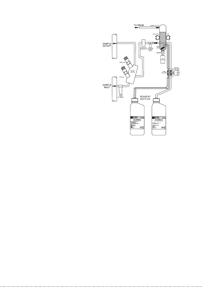
OPERATING DESCRIPTION
BROMINE MEASUREMENT
Referring to the drawing on page 10 and the Fluidic Diagram
on page 17, the Sample Line is connected to the instrument at
the Sample Port (#17); an internal Regulator (#15) reduces
the inlet pressure from a maximum of 4 bar (57.2 psi) down to
1 bar (14.3 psi); from the Regulator a nylon tube is connected
to the input of the Electrovalve (#21). The output of the valve
goes to the Drain Port (#11) and then to the Measuring Cell
(#7). An optional Filter can be installed to the sample port if
the stream is excessively turbid.
The sample coming from the line normally flows through the
Measuring Cell (#7). It goes out from the Measuring Cell
through the Drain Tube (#8) and the Output Port (#9).
The Measuring Cell is accessible from the port placed on the
top (#6) for speedy cleaning and maintenance.
During the 100 seconds preceding the sampling, the analyzer
solenoid input valve is open to allow sample flow to flush the
colorimeter cell. Every 3 to 90 minutes (user selectable), the
electrovalve closes stopping the sample flow and leaving the
sample cell full of fresh sample. Cell volume is controlled by
an overflow gateway.
As the sample inlet electrovalve closes, a series of measurements
(with LED on and off) of the unreacted sample is taken to determine
an average blank level prior to reagent addition.
The measurement of sample blank signal permits compensation
for any turbidity or natural color, and provides the zero reference
point for the measurement.
The two channel Peristaltic Pump (#5) starts rotating causing
a precise quantity of buffer and indicator (#13 and #16) to
enter the colorimeter sample cell. Here a magnetically coupled
stirrer mixes the reagents with the sample.
After a delay for the color development, a series of measurements
(with LED on and off) are taken (sample level) to determine an
average bromine concentration measurement. The reacted
sample signal is then measured and displayed.
This sequence is repeated every 3 to 90 minutes (user-selectable).
16
Page 17
METHOD OF ANALYSIS
The available
bromine
oxidizes the
bromine
reagents at a
pH between
5.5 and 6.0 to
form a magentacolored compound. The
intensity of the
resulting color
is proportional to the
concentration
of bromine in
the sample.
pH AND TEMPERATURE MEASUREMENT
ORP MEASUREMENT
The HI 1005 pH/temperature probe provides at the out port
a potential proportional with the pH. The temperature is
measured with PT100 platinum sensor.
For increased accuracy the pH is corrected with temperature
and with the calibration coefficients. Up to 2 buffers can be
used for calibration.
The temperature can be displayed in °C or °F.
The probe can withstand pressure up to 6 bar (87 psi).
The HI 2008 probe provides at the out port a potential
proportional with the ORP value. The value is directly
displayed in mV.
The probe can withstand pressure up to 6 bar (87 psi).
17
Page 18

INITIAL PREPARATION AND INSTALLATION
INSTALLATION PERSONNEL
Installation of the PCA 311-331 Bromine, pH, ORP and
temperature analyzers should be undertaken by persons with
technical knowledge of the dangers associated with chemical
exposure and electrical shock.
Hanna Instruments assumes that persons performing the installation
tasks are aware of the appropriate safety procedures.
CAUTION: Review the Material Safety Data Sheets (MSDS) before
handling the supplied chemical reagents.
LOCATION OF THE INSTRUMENT
Analyzer Location
Locate the analyzer as close as is reasonably possible to the
point where the sample is withdrawn from the product stream
(referred to as the sampling point).
The instrument should be mounted indoors, out of direct sunlight. Instrument operating temperature is 5 to 40°C (41 to
104°F).
Sampling Point Location
Locate the sampling point to obtain a truly representative sample
from the product stream. For example, be sure the sampling
point is well downstream from a Bromine and acid / alkali
feed. This assures that adequate mixing and reaction of the
Bromine and acid / alkali before a sample is extracted.
HYDRAULIC CONNECTIONS
Note: Hydraulic connections should be installed only by qualified
personnel to assure conformity to applicable plumbing codes.
Sample Line Installation
Direct routing of sample lines is recommended.
If the large process pipes are horizontal, taps should be
inserted vertically in the middle of the pipe to avoid pulling
sediment from the bottom or air bubbles from the top of the
pipe into the sample line.
A 1/2 BSP sample input fitting allows direct connection to the
optional input filter.
18
Page 19
Sample line pressure should be between 0.07 and 4 bar
(1 and 57.2 psi) with an ideal pressure of 0.7 bar (10 psi).
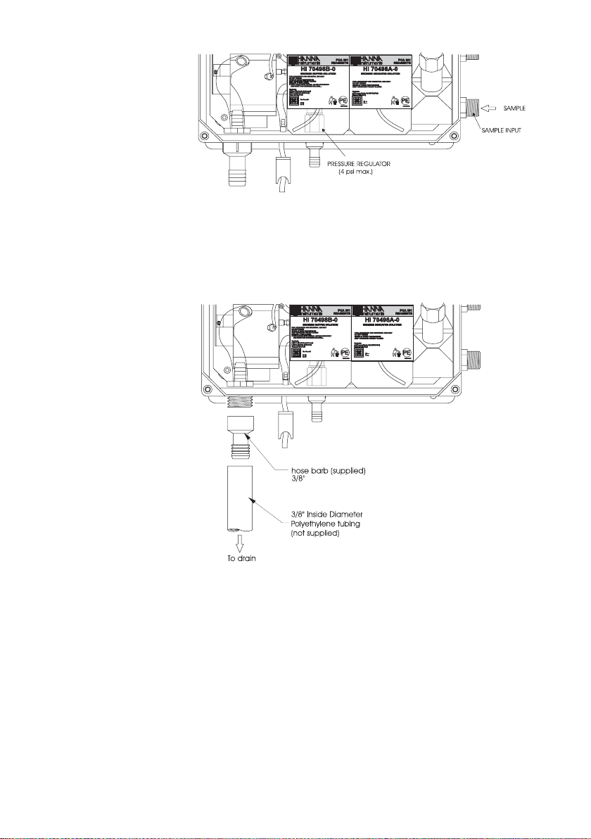
Drain Line Installation
The drain hose fitting is a 20 mm (3/4”) hose barb on the
bottom of the instrument enclosure. An air gap between the
end of the drain hose and the drain is recommended to
prevent any back flow into the instrument in the event of drain
blockage.
Return Line Installation
The return hose fitting is a 12 mm (1/2”) hose barb on the
bottom of the regulator output port and should always be
connected even when pressure is below 1 bar.
19
Page 20
INSTALLING THE INPUT FILTER
PCA301
REAGENTS
HI 70498A-0
BROMINEINDICATORSOLUTION
R:-S:
--
ETICPCA30A
Contents:
p-Toluenesulfonic
Acid(6192-52-5)
Water
(7732-18-5)
FORLABORATORYANDINDUSTRIAL USE ONLY
DO
NOTFREEZE
STORE
ATROOMTEMPERATURE
KEEP
CONTAINERTIGHTLYCLOSED
PCA301
REAGENTS
HI 70498B-0
BROMINEBUFFERSOLUTION
Xn:Harmful
R:
22
S:
46
ETICPCA30B
FORLABORATORYANDINDUSTRIAL USE ONLY
DO
NOTFREEZE
STORE
ATROOMTEMPERATURE
KEEP
CONTAINERTIGHTLYCLOSED
HARMFUL
IFSWALLOWED.
IF
SWALLOWEDSEEKMEDICALADVICE IMMEDIATELY
AND
SHOWTHISCONTAINEROR LABEL.
Contents:
Lithium
Bimaleate(unknown)
Lithium
Maleate(unknown)
Water
(7732-18-5)
BROMINE
PCA-331
Bromine/pH/ORP
Analyzer
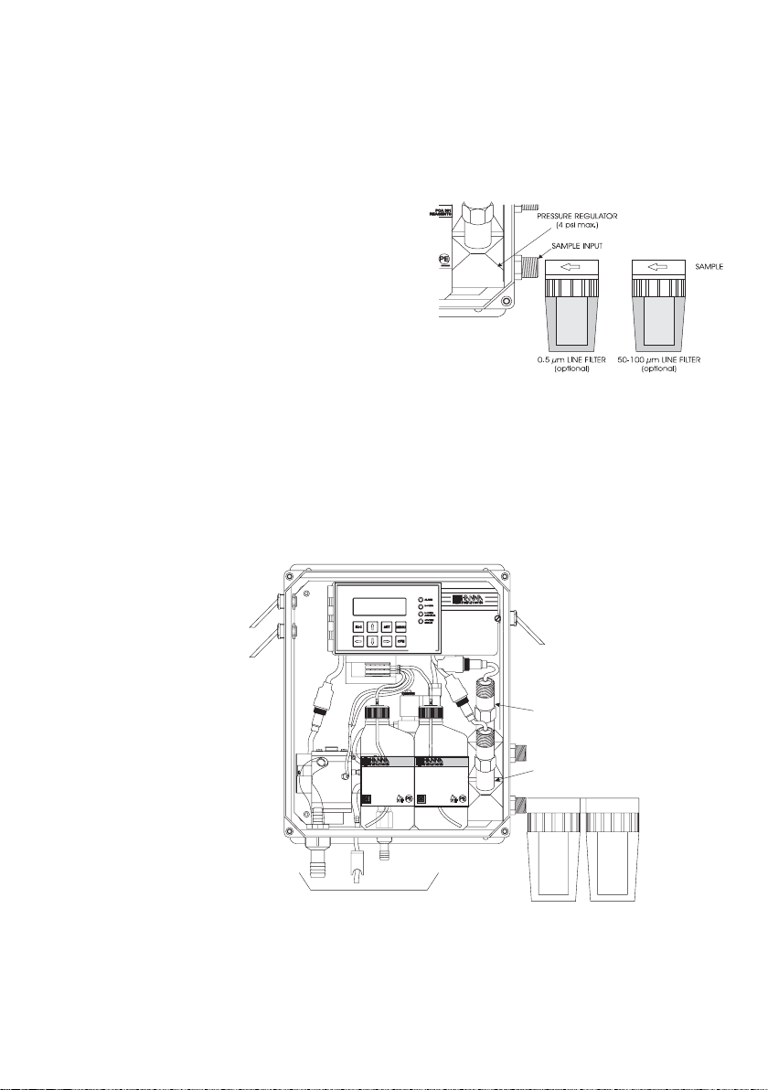
In order to ensure maximum accuracy of measurements, it is
recommended to have always clear sample, with suspended
particles smaller than 0.5 μm. This can be achieved by installing two filters before the sample input.
The type of filters depends on the quality
of the water: the first
filter should have 50100 μm pore size,
whereas in any case
the second filter, the
one closer to the analyzer, has to be 0.5 μm.
For correct installing procedure and maintenance, see the
instructions of filters.
INSTALLING THE pH AND ORP PROBES
To mount the pH and ORP probes, first turn off the analyzer.
Unscrew the closing caps from the electrode holder and remove
the protective cap from electrodes and electrodes connectors.
20
Bromine/pH/ORP
Analyzer
ORP probe
HI 70498B-0
BROMINEBUFFERSOLUTION
FORLABORATORYANDINDUSTRIAL USE ONLY
DONOTFREEZE
STOREATROOMTEMPERATURE
KEEPCONTAINERTIGHTLYCLOSED
HARMFULIFSWALLOWED.
IFSWALLOWEDSEEKMEDICAL ADVICE IMMEDIATELY
ANDSHOWTHISCONTAINER OR LABEL.
Contents:
LithiumBimaleate(unknown)
LithiumMaleate(unknown)
Water(7732-18-5)
Xn:Harmful
R:22
S:46
REAGENTS
PCA301
HI 70498A-0
BROMINEINDICATORSOLUTION
FORLABORATORYANDINDUSTRIAL USE ONLY
DONOTFREEZE
STOREATROOMTEMPERATURE
KEEPCONTAINERTIGHTLYCLOSED
Contents:
p-ToluenesulfonicAcid(6192-52-5)
Water(7732-18-5)
R:-S:--
REAGENTS
PCA301
ETICPCA30A
PH probe
Screw the pH probe (HI 1005) in the lower position and the ORP probe
(HI 2008) in the higher position and assure that no leakage occurs.
Page 21
Only after the probe is in final position connect the probe to the
HI 70479
HI 70473
HI 70474 or HI 70475
From Buffer Bottle
From Indicator Bottle
To "Y" Connector
and Measuring Cell
To "Y" Connector
and Measuring Cell
dedicated connector. Lock the connector with the built in nut.
Warning: Never connect or disconnect the probes when the analyzer is
powered on.
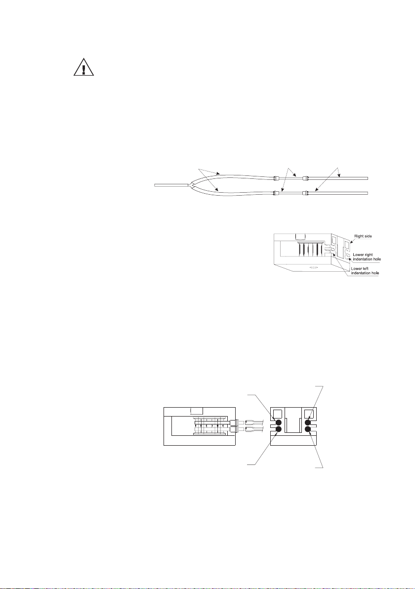
INSTALLING THE PUMP TUBES
Locate the analyzer reagent tubes in the accessory kit. Each
tube is composed of three sections. The sections are joined
together by plastic connectors with plastic collars at the ends
of the center section.
Locate the peristaltic pump.
Feed one tube from the shorter
end section behind the pump
rollers from the right side of the
pump. Seat the plastic collar at
the right end of the center section of tubing into the lower
right indentation hole of the
pump face.
Grasp the other plastic collar and pull, stretching the center
section, and place the grommet in the lower left indentation
hole.
Repeat this process with the second pump tube, placing it in
the upper indentation holes.
From Indicator Bottle
To "Y" Connector
and Measuring Cell
From Buffer Bottle
To "Y" Connector
and Measuring Cell
21
Page 22
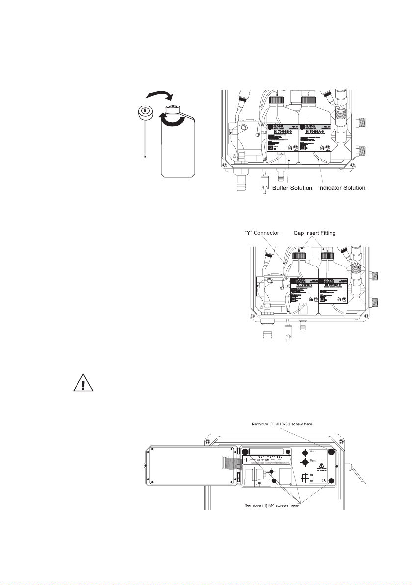
Separate reagent caps are provided in the accessory kit. Put
the supplied caps onto each reagent bottle prior to installing
them. Place the indicator bottle (HI 70498A) on the right and
the buffer bottle (HI 70498B) on the left.
Note: Add the content of 5 HI 70452 sachets, DPD Compound, to the
Indicator Solution prior to installing it.
Connect the longer tube
ends on the left side of the
pump to the reagent bottle
cap insert fitting.
Connect the short ends in
the right side of the pump
to the measuring cell reagent input port through the
“Y” connector.
ELECTRICAL CONNECTIONS
A power cable (3 mt.) is provided with your analyzer. However,
if access to the terminal block is required, see below.
Warning: Electrical connections should be installed only by qualified
personnel to assure conformity to applicable electrical codes.
Unplug the meter before any electrical connection.
22
Page 23
Power Connection
CSR2CSR2
PPCA320P-3
+5V+5V
2
1
2
3
1
M
O
R
3P
MOR3P
1
3
2
M
O
R3
P
MOR3P
1
2
RELICAMRELICAMRELICAM
RELICAM
REDRED
PINKPINK
G
R
EY
GREY
B
LUE
BLUE
G
RE
EN
GREEN
BR
O
W
N
BROWN
YELLOWYELLOW
RELICAMRELICAM
Electrovalve
Phase
Earth
Main Power
Cord
Watertight
Grommet and
Nut Assembly
Neutral
Terminal
blockblock
Ground screw
Transformer
Line FilterLine Filter
Main Power PCBMain Power PCB
24 VAC24
VAC
1
Power connections are made at a terminal block located in the
center of the electrical compartment to the right of the fuses.
Hard wiring with 13 mm (½”) conduit is recommended and
usually required by most municipal electrical codes.
Warning:Before connecting the instrument to the line:
1) Check the label near the fuses for proper voltage.
2) Be sure the power cord is not connected to the line.
3) Open front panel.
4) Remove the cover screws (Allen head).
5) Do not remove peristaltic pump or motor.
6) Unplug all alarms and recorder jacks.
Feed the power cord through the watertight grommet and
tighten the grommet nut. See the picture below for proper wire
connections.
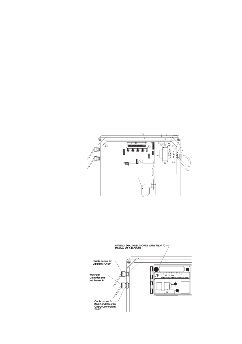
Recorder Output and Relay Access
Hard wiring for alarms and relays recorder output and serial
communication can be accomplished through four watertight connectors on the left side of the enclosure, by passing wires through
the rubber grommet and tightening the nut as described earlier.
Refer to the drawings for proper wire connections.
23
Page 24
ALARM
C
NO
NC
SYSTEM
ERROR
C
NC
RS 485
B
A
I
I
Alarm Relay
Note: The Alarm relay is power-fail safe and is closed when the
System Error Relay
Note: When the meter is in alarm mode or in system error mode, the user
Bromine Dosing Relay
RS485
Note: The RS485 could use also the ground wire to
24
A system alarm feature provides relay activation
to signal that the measuring value exceed the
alarm setpoints. The alarm relay is closed
(Common connect to Normal Close) if the value
is lower than alarm low setpoint or higher than
alarm high setpoint.
The ALARM LED blinks when alarm is active.
analyzer is not powered.
A system error feature provides relay activation to
signal the need for operator intervention through an
SYSTEM
ERROR
external device, such as a buzzer, a light or any
other electrical equipment. When errors appears, the
relay is closed (Common connect to Normal Close).
The SYSERR LED blinks when a system error occurred.
If the situation persists for more than a few samples, the
operator should notify maintenance personnel for investigation
of the problem.
could directly view the alarm or error description on the display.
If GSM transmitter is installed and GSM mode is selected, the
alarms and errors are sent as SMS message.
The System error relay is power-fail safe and is closed when
the analyzer is not powered.
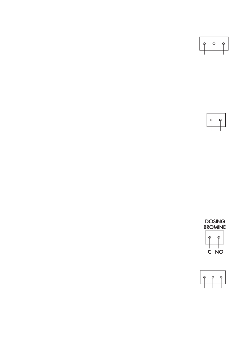
The bromine dosing relay is activated (Common
connected to Normal Open) when bromine
concentration is under the dosing setpoint. The
bromine dosing use a proportional algorithm that
depends on both, setpoint and delta.
The analyzer has RS485 serial communication
RS 485
with selectable baud rate between 1200 and 9600
Bps. The GSM module HI 504900 is also connected using the RS485 port.
prevent common mode voltages.
The DOSING BROMINE LED is turned on when the dosing
relay is closed.
Page 25

Note: The bromine dosing is stopped when the concentration is over
DOSING
pH
C
NO
RECORDER
V
I
I
I
Alarm high setpoint or when a System error related to bromine
measurement occurs.
Acid/alkali Dosing Relay
Acid/alk dosing relay is activated (Common connected to Normal Open) depending on the setpoint
and selected delta. If the analyzer is set to dose
acid, the relay is active when the pH value is over
the setpoint. If alkaline is dosed, the relay is activated when the pH value is under the setpoint.
The DOSING ACID/ALK. LED is turned on when the dosing
relay is closed.
Note: The acid/alk dosing is stopped when system error related to
pH occurs.
Recorder Output
The recommended recorder hookup uses a
twisted pair shielded cable. The shield should
be connected to the terminal at the instrument
end and left open at the recorder end.
To operate with this hookup, the following
conditions are required at the recorder end:
• The input to the recorder must be isolated from the chassis
ground (earth) of the recorder;
• If the recorder has more than one input, they must be
differential inputs.
Several type of outputs are available: 0-10mV, 0-100mV, 0-1V,
0-20 mA or 4-20 mA. The recorder output could be assigned
to Br, pH, Temperature or ORP.
Proportional dosing pump
A proportional dosing pump could be connected to the 4-20 mA
output. The pump could be used to dose bromine or acid/alk as
selected by the user. When the output is 4 mA, the pump must
be stopped and when the output is 20 mA, the pump must
provide the maximum output.
DOSING
pH
25
Page 26

STARTUP
HANNA INSTRUMENTS
PCA 311 Ver. 1.0f
Bromine
Loading language..
To power up the analyzer open the electronic
box door and turn on the main switch.
When the analyzer is powered up, the display
backlight is turned on and the initialization take
place. In this phase, the integrity of the stored
data is checked and the information regarding
the language is loaded.
The display will show HANNA INSTRUMENTS, the name of
the instrument and the software version.
Note: The instrument will display at startup PCA 311, PCA 321 or
PCA 331.
After initialization, the analyzer will show the main panel (or
bromine measuring panel for PCA 311). The measured
values are displayed. The bromine concentration will be
updated only after a full measuring cycle. The first reading is
0.0 mg/L and the dosing relay is not active.
After the first bromine concentration is measured and displayed,
the bromine dosing relay is activated if necessary.
Note: If the SMS feature is selected and correctly configured, the
analyzer will send a SMS at each power up sequence.
26
Page 27

USER INTERFACE
PANELS ORGANIZATION
The PCA 311 – 331 analyzers provide a friendly interface
that display all important parameters of the analyzer. The
appearance of the display could be selected by the user.
The panels are organized
in circular loops. PCA
331 has a main loop
where panels with all
measurements are displayed, bromine measurement loop, pH measurement loop, temperature measurement loop
and ORP measurement
loop where only information related to the parameter is displayed.
PCA 321 has the same structure but without the ORP
measurement panels.
PCA 311 has only the bromine measurement panels.
Pressing “UP” and “DOWN” arrow keys will move inside loop
in a circular way (after last panel, the first panel is displayed).
Pressing “CFM” to move from main panels to measurement
panels. Pressing “ESC” to move from measurement panels to
main panels.
MAIN PANELS
At startup the display
shows one of the
main panels. This
panel contains the
bromine, pH, ORP
and temperature values and the related measuring units. The
panel contains also the current time and the alarm / error
status.
Other panels are available by pressing “UP” or “DOWN”
arrow keys. On each of this panels one measurement is
displayed on the left side and the others on the right side.
27
Page 28

Example: When pH is displayed on the left side and the bromine, ORP
MEASURE PANELS
One row with messages is also displayed.
When the display
show one of this panels, pressing “CFM”,
will enter in the panels related to the parameter displayed in
the left side.
and temperature on the right side, pressing “CFM” will go in
one of the pH measure panels.
For each parameter, several measure panels are available.
One panel contains large digits for better visibility.
The measure panels contains:
12
5
< Low ORP >
Min:4.18 Max:7.00
6.29 pH Error
STANDBY 16:35
08:10
3
4
5.3 mg/L Alarm
<Br Calibration Old>
7
Min:0.0 Max:7.3
1 = the measured value (bromine, pH, ORP or temperature)
2 = the measurement units (mg/L, pH, mV, °C or °F)
3 = the current time in format HH:MM
4 = error or alarm indicator
5 = information about the operating mode.
6 = warnings, alarms and errors, displayed one at a time
7 = the last row displays less important information:
• Maximum and minimum value
• Sampling time
• Reagent doses left
• Alarm High and Alarm Low
• Regulator Setpoint and Delta or Hysteresis
• Analog output maximum and minimum
• Br measuring phase
6
28
Page 29

The display go in large
digits panel if no key
is pressed for about 4
minutes. If key is
pressed, the display
returns in the panel
where it was before.
Pressing “ESC” when in one of those panels will return in
main panels mode.
MESSAGES
When warnings, alarms or errors appears, the message line is
displayed. The meanings of each message is explained in
chapter ERRORS, ALARMS AND WARNINGS.
If many messages are present, the “<“and “>” signs are
displayed on the left and/or the right side.
Pressing “LEFT” or “RIGHT” arrow keys the messages are
scrolled. If is no message in the left or right side, the
corresponding sign “<“ or “>” disappears.
When at least one alarm is active, the “Alarm” appears in the
right side of the display. The ALARM LED will start to blink.
When errors or both, errors and alarms are active, “Error”
appears in the right side of the display. The SYSTEM ERROR
LED will blink.
The “MANUAL” or “STANDBY” information is displayed on the
first line of the LCD.
MENU MODE
By pressing “MENU” key, the analyzer will enter in menu mode.
In this mode, the analyzer settings can be consulted or modified.
The settings are organized in menus and grouped by functions.
The menu is password protected.
PASSWORD PROCEDURE
When the “MENU” key is pressed, the analyzer ask for the
password.
If the password is set to
“0000” (default value)
the analyzer will not
ask for password.
Enter password:0000
29
Page 30
If correct password is entered and confirmed, the analyzer will
go in menu mode.
If wrong password is entered, the analyzer displays “Password
incorrect. Settings are not allowed!”, and the user could only
view the analyzer parameters.
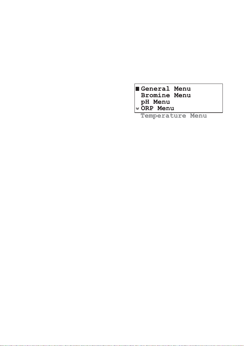
NAVIGATING THROUGH MENU
The menu is organized as a list of options. Each line of this
list:
- could contain a
sub-menu;
- could display an
analyzer parameter or
- could start a function.
To select a menu line, press “UP” or “DOWN” arrow keys.
The selected line is signaled by a black square in the left side
of the display.
If the menu continues outside the viewing area, a double up
or down arrow is displayed on the first or last line of the display.
As a general rule, the “CFM” key will descend into menu and
“ESC” key will return to a higher level.
Pressing “CFM” will make the following actions:
• descend into the sub-menu for sub-menu line.
• no action for parameter line.
• start the function for function line.
Pressing “ESC” will make the following actions
• Return in measure mode when in the main menu
• Return in the previous menu when in submenu
• Return from function before the normal ending
when function is executing
• Exit from edit mode without saving.
MODIFY A PARAMETER
To modify a parameter, press “SET” key when a line that
displays a parameter is selected.
The cursor will go to the first digit or letter of the parameter.
Note: If wrong password is entered, editing is not allowed.
The editing sequence depend upon the parameter type.
30
Page 31

For list type parameter
In this case the cursor will blink and first letter alternates with a
black square. To modify the value press “UP” or “DOWN”
arrow keys until the correct value appears.
Press “CFM” to save the value or press “ESC” to end the
editing without saving the value.
For single numeric values
In this case the cursor will blink by alternating the first digit
and a black square.
Press “RIGHT” or “LEFT” arrow keys to focus on the digit that
has to be edited.
To edit the current digit press “UP” or “DOWN” arrow keys.
Press “CFM” to save the value or press “ESC” to end the
editing without saving the value.
For many numeric values on a row
In this case the cursor will go to the first digit of the first
parameter. The cursor will blink but no black square will be
displayed.
Select the parameter to be edited by pressing “RIGHT” or “LEFT”
arrow keys.
Set Time: 10:31
Set Date:2004/01/01
To edit the parameter press “SET” key again and the black
square alternating with the first character appears, signaling
that the parameter could be edited.
Depend on the parameter type, the edit procedure is as
described for list type or single numeric value.
Press “CFM” to save the value or press “ESC” to end the
editing without saving the value. The cursor will prompt the
edited parameter.
31
Page 32

Pressing “RIGHT” or “LEFT” arrow keys, another parameter
can be set.
Pressing “ESC” key will return to menu.
Note: If the edited value is outside the allowed range, a warning
panel appears when “CFM” is pressed. This panel contains
the parameter limits. Pressing again “CFM” or “ESC” will
return to the edit mode.
PROGRAMMING THE ANALYZER
The parameters are stored in a nonvolatile EEPROM memory. If
a power failure appears the settings are restored after power on.
When power is first time applied to PCA 311-331 analyzers,
the parameters are set to factory default values.
32
Page 33

GENERAL SETTINGS
The analyzer settings,
common for all measurements, are grouped
in “General Menu”.
System Log
Analog Output
SMS Settings
Serial & GSM Comm.
Time and Date
System Functions
CHANGING THE PASSWORD
The password is a numeric value with 4 digits.
To change the password, enter in “General Menu” - “System
Functions” and edit the “Change Pass” line. Press “CFM” to
save.
After new value is confirmed, the displayed password is set to
0000 for protection against unauthorized reading.
SETTING THE LANGUAGE
The PCA 311-331 analyzers has 4 languages stored inside.
The user could easily change the language without restarting
the analyzer.
To select a new language, enter in “General Menu” - “Language
Change” and select the new language. After pressing “CFM”
key, the new language is loaded.
ANALYZER SERIAL NUMBER AND SOFTWARE VERSION
The unique serial number can be viewed by selecting the
“General Menu” - “System Functions” - “Serial Nr.”.
Serial number is not editable.
The software version is displayed each time the analyzer is
turned on and lasts during the initialization phase.
TIME AND DATE
The PCA 311-331 analyzers have a built in real time clock.
When the analyzer is in normal mode, the current time is
displayed on the right side of the display in HH:MM format.
To set the time and
date, select the “General Menu” - “Time
and Date”. Set the time
and the date as described in the User interface chapter.
Language Change
Set Time: 10:31
Set Date:2004/01/01
33
Page 34
WORKING MODE
Three working modes
could be selected for
the analyzer. The selection is available in
“General Menu” “System Functions” “Manual Commands”
- “Work Mode”.
The work mode could
be set as AUTOMATIC,
STANDBY or MANUAL.
AUTOMATIC MODE
In this mode the analyzer performs the measurements
continuously accordingly with the settings.
STANDBY MODE
When in standby, the sampling electrovalve is closed, the
measurements are stopped and the peristaltic pump is
activated for 2 seconds each 100 minutes to preserve the
elasticity of the tubes.
The display will show “STANDBY” on the first line when in the
measurement mode. The bromine, pH, ORP, and
temperature displayed values will be all time the last
measured ones.
The SYSTEM ERROR LED is always on (no blinking).
Note: When the analyzer exit from STANDBY, the relays and corre-
sponding LED’s are activated only after a new value is read.
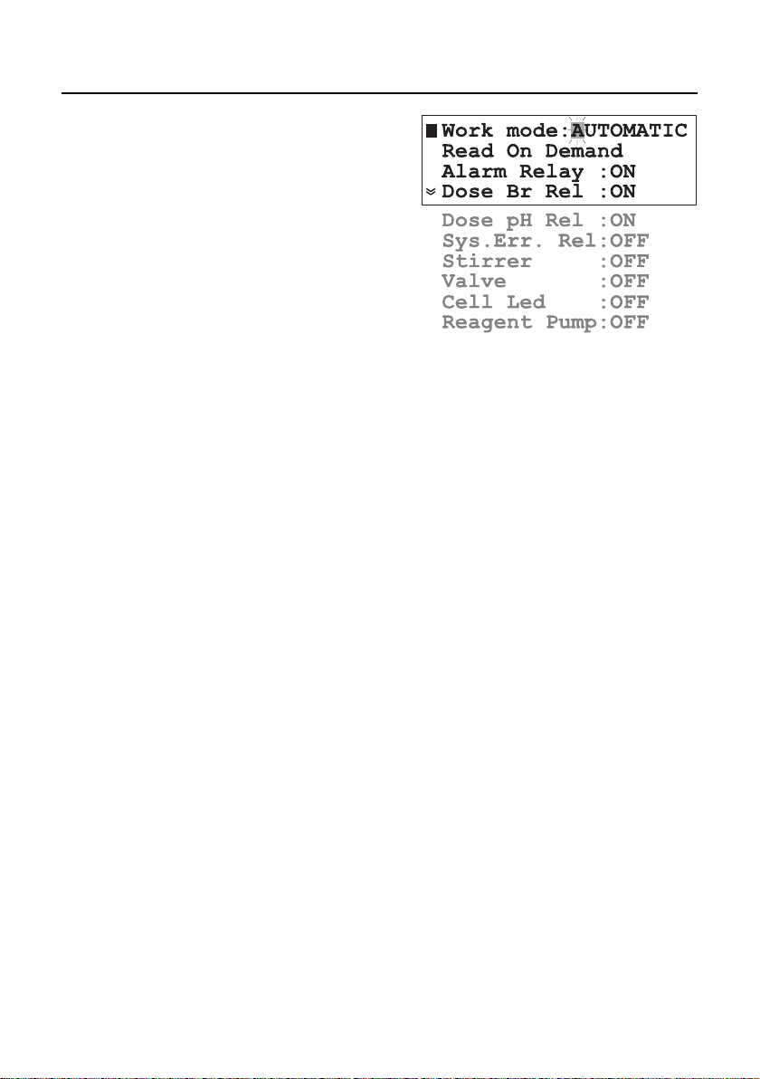
MANUAL MODE
For testing, maintenances and setup purposes, the analyzer
has the possibility to use direct manual commands.
In this operating mode, by setting the “Alarm Relay”, “Dose Br
Rel.”, “Dose pH Rel.”, “Sys. Err. Rel”, “Stirrer”, “Valve”, “Cell
Led” and “Reagent Pump” as “ON” or “OFF” will turn on or
off the corresponding device.
The display will show “MANUAL” on the first line when in the
measurement panels. The displayed values will be the last
measured ones and the measuring sequence is stopped.
When in manual mode the ALARM LED is always on (no blinking).
34
Page 35

Note: The read on demand function is active only when the analyzer
DIRECT READ
SYSTEM ERROR RELAY
READ ON DEMAND
When this function is selected, (“General Menu” - “System
Functions” - “Manual commands” - “Read On Demand”) a
new bromine measuring cycle is immediately started.
This command is useful when calibrate or whenever an
immediate result is needed.
is in automatic mode.
For rapid diagnostics of the measuring cell, the converter
readings for dark (cell LED off) and blank (cell LED on) could
be consulted.
To display the dark reading activate the “General Menu” “System Functions” - “Dark Read” function. After confirmation
the dark value is displayed.
Manual Commands
Dark Read
Blank Read
Change Pass: 0000
To display the blank reading activate the “General Menu” “System Functions” - “Blank Read” function.
After confirmation the blank value is displayed.
If the cell work correctly, the values must be between -20000
and 20000 with a minimum difference blank – dark of 20000
converter points.
The PCA321-331 controller has a single system error relay for
all measured parameters.
To allow bromine errors to activate the relay, set “Bromine
Menu” - “Alarm&Err Bromine” - “Err.Relay” to Active.
For pH errors set the item “pH Menu” - “Alarms&Err pH” “Err. Relay” to Active.
For ORP errors set the item “ORP Menu” - “Alarms&Err ORP”
- “Err. Relay” to Active.
For temperature errors set the item “Temperature Menu” -
“Alarms&Err Temp.” - “Err. Relay” to Active.
35
Page 36

BROMINE SETTINGS
The settings related to
bromine measurement
are grouped in “Bromine Menu”. The following options are
available:
REAGENT CHANGING
One set of reagents is enough for at least 16000 samples.
The remaining doses of
reagent are displayed
on one bromine measuring panel.
When the reagent is
changed, several actions
must be performed:
Prepare the reagent and install the new bottles as described in
initial preparation and installation chapter.
Prime the reagent pump if needed or simply reset the reagent
counter.
The used reagent doses and the remaining reagent doses could
be viewed on the first two lines when enter in “Bromine Menu”
- “Reagent change”.
If “Bromine Menu” - “Reagent change” - “Reset Reag.
Counter” function is selected and confirmed, the used doses
become 0 and the remaining doses become 16000.
This command does not perform a priming of the reagent
pump.
If “Bromine Menu” “Reagent change” “Prime Reag. Circuit”
function is selected and
confirmed, the dosing
pump is turned on for 180 seconds. The remaining time is
displayed on the right-down corner of the display.
The process could be terminated by pressing “ESC” at any
moment.
Priming in progress
...
168s
36
Page 37
MEASURE SETTINGS
MEASURE INFO
ANALOG OUTPUT
Select “Bromine Menu” - “Measure Settings” and set the
“Period” between 3 and 90 minutes.
Period (sampling rate) is the elapsed time between two
consecutive bromine measurements. The sampling rate is also
important when the analyzer is used for bromine dosing. For
larger pools, the period must be longer, and for smaller pools,
the period must be shorter.
The sampling rate can be quickly consulted on one bromine
measuring panel.
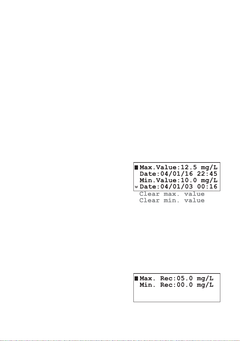
The analyzer calculates the maximum and minimum
concentration value since the first measurement.
The maximum and minimum can be quickly consulted on
bromine measuring panel.
To see information about these values, select “Bromine Menu”
- “Measure Info”. The time stamp when maximum and
minimum appears are also displayed in this menu.
To reset the maximum
or minimum values,
select the functions
“Bromine Menu” “Measure Info” “Clear Max. Value” or
“Bromine Menu” “Measure Info” “Clear Min. Value”.
The maximum or minimum value will be set to the current
read value.
The type of analog output can be set as described in “Analog
output” chapter. The analog output span for bromine could
be set in “Bromine Menu” - “Analog Output Br”.
“Min. Rec” will set the recorder lower limit and “Max. Rec”
will set the recorder
higher limit. The Max.
Rec. value must be
greater than Min.
Rec. value.
37
Page 38

Example: if the 0.0 to 1.0 V recorder output has been selected, the
BROMINE DOSING
Note: If the measured concentration is lower than setpoint minus
Example: For setpoint 8.0 mg/L, delta=2.0, sample rate 10 minutes and
The output will be proportional with bromine if the read value
is between those limits.
operator can select 0.0 V to correspond to a concentration of
5.0 mg/L (Min. Rec. setting) and 1.0 V to correspond to a
concentration of 7.5 mg/L (Max. Rec. setting).
The full scale span of the recorder would then be 2.5 mg/L,
yielding a magnified view of the 5.0 to 7.5 mg/L concentration range on the recorder.
The analog output limits can be quickly consulted in one of
the iodine measuring panels.
The PCA 311-331 analyzers contain a simple
proportional dosing algorithm. Proportional
dosing establishes and
maintains a controlled
and consistent concentration level.
The analyzer has a relay for bromine dosing and also the
4-20 mA output could be configured as a dosing output.
The equation for determining the time for relay on is:
dosing time = (set value -measured val ue)*Period/Delta.
The analog output will have the value:
analog output [mA] = 4 + 16 * dosing time/Period [mA]
delta, the dosing will be continuous until the next measurement is taken (one period).
measured value 7.5 mg/L, the proportional dosing will be active
for the initial 2 minutes and will stop for the remaining 3 minutes.
In fact: Time = (8.0-7.5)*10/2.0 = 2.5 minutes
Analog output = 4 + 16*2.5/10 = 8 mA
To modify the dosing
setpoint, enter the
“Bromine Menu” “Dosing control Br”
and edit the “Setpoint”
line. The value must
be between 0.1 and
9.9 mg/L.
38
Page 39

To modify the Delta, edit the “Delta” line. The available values
are 0.2, 0.4, 0.6, 0.8, 1.0, 1.2, 1.4, 1.6, 1.8, 2.0, 3.0, 4.0.
Note: The speed of the analyzer could be modified by changing the
sampling rate. A new decision regarding the bromine regulator
is taken only after a new measurement.
The Setpoint and Delta could be quickly consulted on one
bromine measuring panel.
LOW READING PROTECTION
To prevent excessive bromine dosing if the detector is not
working properly or the reagent bottle is empty, a “Detector
Error” is generated if the measured bromine value is under
the low point value. This error is generated only if the low
point feature is set active.
The bromine dosing is stopped and the SYSTEM ERROR LED
starts blinking.
To enable this feature, edit “Bromine Menu” - “Dosing control
Br” - “Low Point” value and set the “Low Point” status as
“Active”. The allowed value is 0.0 to 2.0 mg/L.
OVERDOSING PROTECTION
To prevent overdosing a “Detector Error” is generated if the
dosing command is on for the Max. ON time and the read
value is changing less than 0.1 mg/L.
The chlorine dosing is stopped and the SYSTEM ERROR LED
starts blinking. The dosing could be resumed only by restarting
the controller.
To enable this protection, edit “Bromine Menu” - “Dosing
control Br” - “Max. ON” value and set “Max. ON” status as
“Active”. The allowed range is between 30 and 720 minutes.
ALARMS
Two alarm setpoints are available for bromine: Alarm high
and Alarm low.
The ALARM LED and alarm relay are activated when the
bromine concentration is higher than Alarm high or lower
than Alarm low.
To modify the alarm setpoints, enter the “Bromine Menu” “Alarms Bromine” and edit “Alarm Hi” or “Alarm Lo” value.
39
Page 40
The alarms could be separately activated or inactivated.
To modify the alarms status, enter the “Bromine Menu” - “Alarms
Bromine” menu and edit “Alarm Hi” or “Alarm Lo” status.
When the status is set to “Inactive”, the alarm is ignored.
Note: The Alarm high must be greater than Alarm low value. The
analyzer display a warning if the settings are incorrect.
The Alarm high setpoint and Alarm low setpoint could be
quickly consulted on one bromine measuring panel. When
an alarm is disabled, the —.— is displayed instead of alarm
value.
CALIBRATE THE MEASURING CELL
The PCA 311-331 analyzers have the possibility to calibrate
the measuring cell.
When a new calibration is performed, calibration factor is
recalculated and all measurements are multiplied with it.
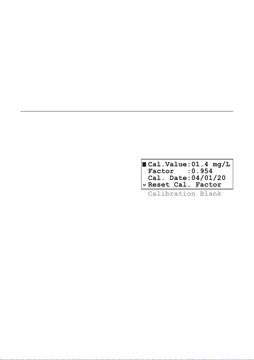
CALIBRATION DATE AND FACTOR
The last calibration
date can be found in
the “Bromine menu” “Cal. Measuring Cell”
- “Cal. Date”. Calibration date is in the
YY / MM / DD format.
A warning “Br Calibration Old” is displayed if one month
elapsed from the last calibration.
The calibrated date is updated after a new calibration is done.
The calibration factor is displayed in “Bromine menu” - “Cal.
Measuring Cell” - “Factor”.
The default calibration factor is 1.000. Each measurement
result is multiplied with calibration factor.
The calibration factor could be reset to 1.000 by activating
the “Bromine menu” - “Cal. Measuring Cell” - “Reset Cal.
Factor” function.
CALIBRATION PROCEDURE
To calibrate the measuring cell, follow the steps:
• Withdraw a sample of the measured liquid directly from the
drain port of the measuring cell (#11) by opening its valve
(#10) - see figure on page 10.
Note: Withdraw the sample just before the electrovalve stops the
liquid flow to the measuring cell.
40
Page 41

• With a calibrated meter take a measure of the sample. This
is the calibration value.
• Wait for the PCA to display the new reading.
• Go in “Bromine menu” - “Cal. Measuring Cell” and edit
“Cal. Value” field.
• Enter the calibration value and save with “CFM”.
• The calibration coefficient and the calibration date will be
updated.
• Press repeatedly “ESC” to exit from menu mode. The
displayed bromine concentration will be equal with the
calibration value.
Note: It is not recommended to calibrate the analyzer at values below
4 mg/L in order to maintain enough accuracy in the whole
range. Calibration below 2 mg/L does not guarantee declared
accuracy outside an interval of ±50% from the calibration value.
pH SETTINGS (PCA 321, PCA 331)
Settings related to pH
measurement are
grouped in “pH
Menu”. The following options are
available:
MEASURE INFO
The analyzer calculates the maximum and minimum pH value
since the first measurement.
The maximum and minimum can be quickly consulted on one
pH measuring panel.
For more detailed information select “pH Menu” - “Measure
Info” The “Max. Value” and “Min. Value”. The time stamp when
maximum and minimum occurs are also displayed in this menu.
To reset the maximum
or minimum values,
select the functions
“pH Menu” - “Measure Info” - “Clear
Max. Value” or “pH
Menu” - “Measure
Info” - “Clear Min.
Value”.
The maximum or minimum value is set to the current read value.
Max.Value:14.00 pH
Date:03/01/01 14:39
Min.Value:00.00 pH
Date:04/01/01 00:03
Clear Max. Value
Clear Min. Value
41
Page 42
ANALOG OUTPUT
pH DOSING
PROPORTIONAL DOSING
The type of analog output could be set as described in “Analog
output” chapter. The analog output span for pH could be set in
“pH Menu” - “Analog Output pH”.
“Min. Rec” will set the recorder low limit and “Max. Rec” will
set the recorder high limit. The Max. Rec. value must be greater
than Min. Rec. value.
The output will be proportional with pH value if the read value
is between those limits.
The analog output limits could be quickly consulted in one of
the pH measuring panel.
The PCA 321 and PCA 331 can use ON/OFF or proportional
dosing algorithm to stabilize the pH.
The analyzer has a relay for acid or alkali dosing and also the
4-20 mA output could be configured as a dosing output.
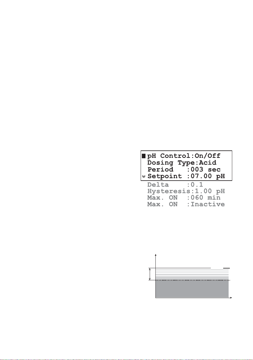
To select the type of pH
dosing edit the “pH
Menu” - “Dosing
Control pH” - “pH
Control” line.
The available options
are Proportional and
ON/OFF.
The acid or alkali dosing is set in the “pH Menu” - “Dosing
Control pH” - “Dosing Type”. When “Acid” is selected, the
analyzer will dose when the pH value is higher than the setpoint
and when “Alk” is selected, the analyzer will dose when the
pH value is lower than the setpoint.
The proportional dosing
algorithm turns on the
dosing relay proportion-
pH
Proportional dosing
delta
Relay off
Setpoint
ally with the difference
between the setpoint and
measured value.
Relay on
time
The equation for determining the time for relay on is:
dosing time = (set value - measured value)*Period/Delta
42
Page 43

The analog output will have the value:
analog output [mA] = 4 + 16 * dosing time/Period [mA]
Note: If the measured pH is lower (or higher for acid dosing) than
setpoint minus (plus) delta, the dosing will be continuous until
the pH period elapsed.
To modify the dosing setpoint, enter the “pH Menu” - “Dosing
Control pH” edit the “Setpoint” line. The value must be
between 2.00 and 12.00 pH.
To modify the Delta, edit the “Delta” line. The available values
are 0.1, 0.2, 0.3, 0.4, 0.5, 0.6, 0.7, 0.8, 0.9, 1, 1.5, 2.
To modify the dosing time edit the “Period” line. The allowed
values are between 3 and 120 seconds.
Note: The period is related only to the dosing process. The pH
measurement take place with a higher rate.
Note: The speed of the analyzer could be modified by changing the
regulator period. A new decision regarding the pH dosing is
taken only after one period elapsed.
The Setpoint and Delta could be quickly consulted on one pH
measuring panel.
ON/OFF DOSING
If this mode is selected the Period and Delta has no effect. The
algorithm will use only Setpoint and Hysteresis.
For alkaline dosing, the
relay will stay on until the
pH increases to the setpoint plus hysteresis value,
then the relay stays off until
the pH decreases to a
value equal to setpoint.
For acid dosing, the relay will stay on until the pH decreases
to the setpoint minus hysteresis value, then the relay stays off
until the pH increases to a value equal to setpoint.
To set the hysteresis edit the “pH Menu” - “Dosing Control
pH” - “Hysteresis” line. The hysteresis value must be between
0.05 and 2.00 pH.
OVERDOSING PROTECTION
To prevent overdosing a “Detector Error” is generated if the
dosing command is on for the Max. ON time and the read
value is changing less than 0.1 pH.
The acid/alkali dosing is stopped and the SYSTEM ERROR
LED starts blinking. The dosing could be resumed only by
restarting the controller.
pH
Hysteresis
Setpoint
Relay on
Relay off
Relay off
Relay on
Relay on
time
43
Page 44

To enable this protection, edit “pH Menu” - “Dosing control
pH” - “Max. ON” value and set “Max. ON” status as “Active”.
The allowed range is between 30 and 720 minutes.
ALARMS
Two alarm setpoints are available for pH: Alarm high and
Alarm low.
The ALARM LED and relay are activated when the pH value is
higher than Alarm high or lower than Alarm low.
To modify the alarms setpoints, enter the “Alarms pH” menu
and edit “Alarm Hi” value or “Alarm Lo” value.
The alarms can be separately activated or inactivated.
To modify the alarms status, enter the “pH Menu” - “Alarms
pH” menu and edit “Alarm Hi” status or “Alarm Lo” status.
When the status is set to “Inactive”, the alarm is ignored.
Note: The Alarm high value must be greater than Alarm low value.
The analyzer display a warning if the settings are incorrect.
The Alarm high Setpoint and Alarm low setpoint could be quickly
consulted on one pH measuring panel. When an alarm is
disabled, the —.— is displayed instead of alarm value.
pH CALIBRATION (PCA 321, PCA 331)
It is recommended to perform pH calibration when the probe
is replaced and after any cleaning action.
The analyzer can perform 2 points calibration, 1 point
calibration or process pH calibration.
To perform any pH calibration enter in “pH Menu” - “Cal. pH
Probe”.
Initial Preparation
44
Set Default pH Cal.
Process pH Cal.
Buffer pH Cal.
Cal. Date :01/01/01
In this menu the last calibration date is displayed on the “Cal.
Date” line. If the probe calibration is older than 1 month, a
warning is displayed.
Pour small quantities of pH 7.01 (HI 7007) and pH 4.01
(HI 7004) or 10.01 (HI 7010) solutions into individual
beakers. If possible, use plastic beakers to minimize any EMC
interference. Also NIST buffers of 6.86 or 9.18 could be used.
Page 45

For accurate calibration use two different beakers for each
buffer solution, the first one for rinsing the probe and the second one for calibration. By doing this, contamination between
buffers is minimized.
Unscrew the probe from its position. Take care to stop the
sample flow before removing the probe. If necessary, disconnect the probe from analyzer to prevent the damage of the
probe cable.
ONE POINT CALIBRATION
Immerse the pH probe into the buffer solution
(e.g. pH 7.01) until the metal ring is immersed,
then stir gently.
Select the “pH Menu” - “Cal. pH Probe” - “Buffer
pH Cal.”.
• The analyzer will prompt to select the first buffer. Select the
buffer (e.g. pH 7.01) using “UP” or ”DOWN” arrow keys
and confirm.
• The analyzer checks
for readings stability.
During this period,
the “Wait for stabilize” message is
displayed.
Note: If the read value, calculated with the default offset and slope,
is different from the expected value with more than 1.15 pH
(i.e. offset > 68mV), the “Wrong calib. values” message is
displayed.
The message “Wrong calib. values” appears also if the pH
probe is defective or not connected. The problem could be
identified if the buffer set value is compared with the actual
read value (first and second line of the display).
If the probe is inserted in the appropriate buffer, the measuring
cycle is restarted automatically and message “Wait for stabilize”
is displayed again.
• If the temperature reading is wrong, the value is set to 25 °C
and a blinking “*” is displayed near it, indicating that is not
the real temperature value. The calibration procedure is not
interrupted.
• When the reading become stable, the analyzer displays
“Stable... press CFM”.
Probe
pH 7.01
Buffer 1 pH: 7.01
Measured pH: 7.02
Temp. [ºC]: 25.1
Wait for stabilize
45
Page 46

• The analyzer prompts for the second buffer selection, and
displays the message “Select buffer pH... or press SET for
one point cal.”.
Pressing “SET” key will end the one point calibration procedure.
TWO-POINTS CALIBRATION
• To perform a two-points pH calibration follow the steps described at one-point calibration until the analyzer displays the
message: “Select buffer pH... or press SET for one point cal.”.
• Immerse the pH electrode into the second buffer
solution (e.g. pH 4.01) until the metal ring is
immersed, then stir gently.
• Press “UP” or “DOWN” arrow keys to select
the second buffer from the list to continue the
calibration and confirm with “CFM”.
Note: The difference between the first and second buffer must be
more than 1 pH unit in order to assure the calibration accuracy. Calibration using 7.01 and 6.86 pH or 10.01 and 9.18
pH is not allowed.
• The analyzer checks for readings stability. During this period,
the “Wait for stabilize” message is displayed.
• When the reading becomes stable, the instrument checks if
the calculated slope is between 47.3 and 68 mV/pH. If the
value is not within this range, the message “Wrong calib.
values” is displayed. In this case it is necessary to perform a
cleaning procedure (see “Electrode conditioning and
maintenance” section) or to replace the probe.
• If the value is accepted, the analyzer displays “Stable... press
CFM”.
Pressing CFM, the two point calibration is completed.
PROCESS pH CALIBRATION
The PCA 321 and PCA 331 has the possibility to calibrate the
pH probe without using buffers and without dismount the
probe. For doing this calibration, a reference pH-meter must
be used. To complete the process calibration, follow the steps:
Probe
pH 4.01
46
• Pour a quantity of sample in a beaker. Use the sample of the
measured liquid directly from the drain port of the measuring
cell (#11) by opening it’s valve (#10) to do this as described
in the Calibration Procedure chapter.
• Place the pH probe of the reference meter in the beaker and
stir gently.
Page 47

• Wait for readings to stabilize.
• Enter in “pH Menu”- “Cal. pH Probe” - “Process pH Cal.”
and enter in the
“Cal. Value” field
the reading from the
reference pH meter.
• Press “CFM” key
when the analyzer
prompt for “Overwrite pH cal. ?”.
•The analyzer checks for readings stability (see One-point calibration) and when the value is stable the message “Stable...
press CFM” is displayed.
• Pressing “CFM” key will complete the process pH calibration.
Note: The calibration could be terminated at any time by pressing
“ESC”. In this case the new calibration is not saved and the
old one remains effective.
SET DEFAULT CALIBRATION
When a new probe is connected or for any reason the current
calibration is wrong and new calibration can not be performed,
the default calibration values could be set. In this case the
slope is set to 59.16 mV/pH and the offset is set to 0 mV.
To accomplish that, select “pH Menu” - “Cal. pH Probe” “Set Default pH Cal.”
The analyzer will ask “Reset the pH cal. to default ?” and if
“CFM” key is pressed will replace the existing calibration coefficients with the default values.
Cal. Value:06.84 pH
47
Page 48
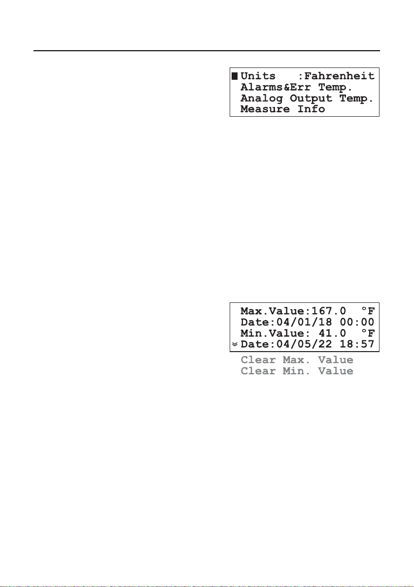
TEMPERATURE SETTINGS (PCA 321, PCA 331)
Settings related to
temperature measurement are grouped
in “Temperature
Menu”. The following
options are available:
UNITS
The analyzer could display the Temperature using Celsius or
Fahrenheit temperature units.
To select the temperature units, edit the “Temperature Menu” “Units” line. Select Celsius or Fahrenheit and confirm.
Note: The temperature values sent via SMS are always the Celsius
values.
MEASURE INFO
The analyzer calculates the maximum and minimum temperature
value since the first measurement.
The maximum and minimum can be quickly consulted on one
temperature measuring panel.
For more detailed information select “Temperature Menu” “Measure Info”. The
“Max. Value” and
“Min. Value” are
displayed and also
time stamp when
maximum and minimum occurs are displayed in this menu.
To reset the maximum or minimum values, select the functions
“Temperature Menu” - “Measure Info” - “Clear Max. value”
or “Temperature Menu” - “Measure Info” - “Clear Min. value”
The maximum or minimum value is set to the current read
value.
ANALOG OUTPUT
The type of analog output could be set as described in “Analog
output” chapter. The analog output span for temperature could
be set in the “Temperature Menu” - “Analog Output Temp.”.
“Min. Rec” will set the recorder lower limit and “Max. Rec”
will set the recorder higher limit.
48
Page 49

ALARMS
The Max. Rec. value
must be greater than
Min. Rec. value. The
output will be proportional with temperature value if the read
value is between those
limits.
The analog output limits could be quickly consulted in one of
the Temperature measuring panel.
Two alarm setpoints are available for temperature: Alarm high
and Alarm low.
The ALARM LED and relay are activated when the temperature
value is higher than Alarm high or lower than Alarm low.
To modify the alarms
setpoints, enter the
“Temperature Menu”
- “Alarms Temperature” and edit “Alarm
Hi” or “Alarm Lo”
value.
The alarms could be separately activated or inactivated.
To modify the alarms status, enter the “Temperature Menu” -
“Alarms Temperature” menu and edit “Alarm Hi” or “Alarm
Lo” status.
Note: The Alarm high value must be greater than Alarm low value.
The analyzer display a warning if the settings are incorrect.
The Alarm high setpoint and Alarm low setpoint could be
quickly consulted on one temperature measuring panel. When
an alarm is disabled, the —.— is displayed instead of alarm
value.
49
Page 50
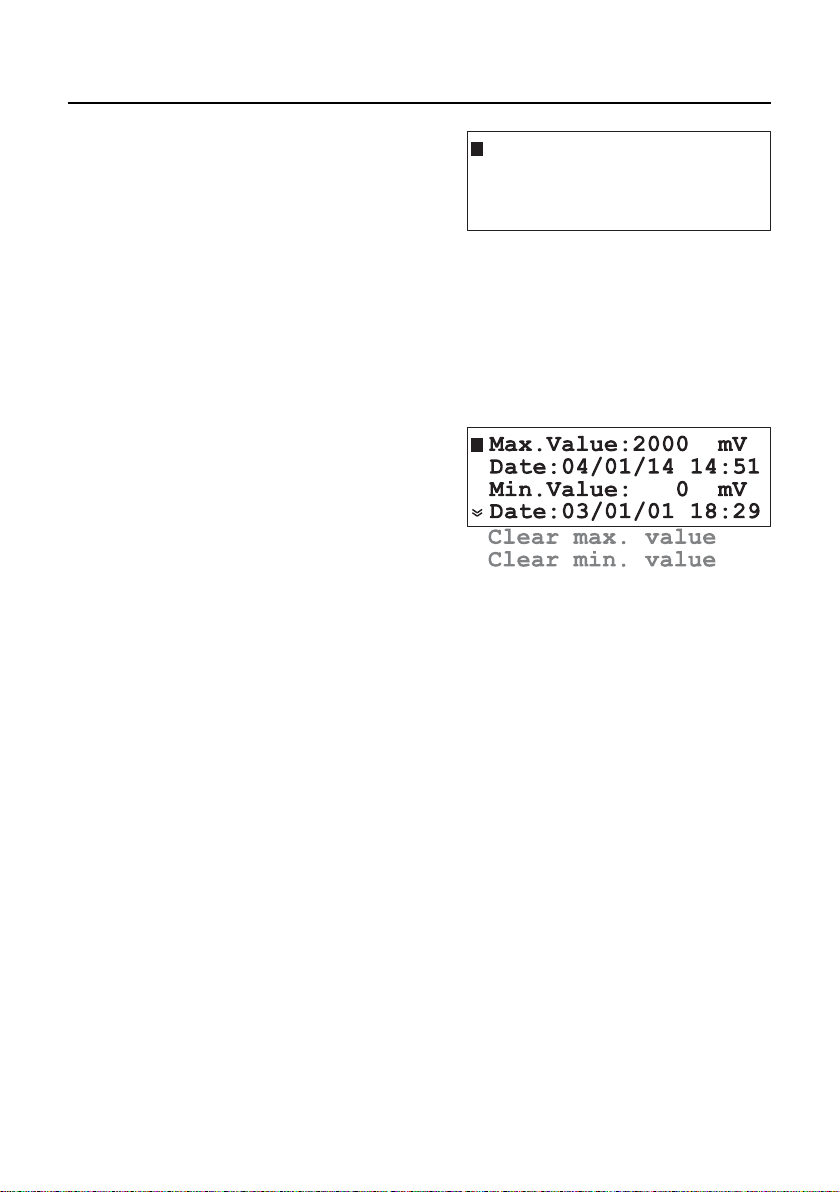
ORP SETTINGS (PCA 331)
MEASURE INFO
ANALOG OUTPUT
Settings related to ORP
measurement are
grouped in “ORP
Menu”. The following
options are available:
The analyzer calculates the maximum and minimum ORP value
since the first measurement.
The maximum and minimum can be quickly consulted on one
ORP measuring panel.
For more detailed information select “ORP Menu” - “Measure Info” The “Max.
Value” and “Min.
Value” are displayed
and also time stamps
when maximum and
minimum occurs are
displayed in this
menu.
To reset the maximum or minimum values, select the functions
“ORP Menu” - “Measure Info” - “Clear Max. Value” or “ORP
Menu” - “Measure Info” - “Clear Min. Value”
The maximum or minimum value is set to the current read
value.
The type of analog output could be set as described in “Analog
output” chapter. The analog output span for ORP could be
set in the “ORP Menu” - “Analog output ORP”.
“Min. Rec” will set the recorder lower limit and “Max. Rec”
will set the recorder higher limit. The Max. Rec. value must be
greater than Min. Rec. value.
The output will be proportional with ORP value if the reading
is between those limits.
The analog output limits could be quickly consulted in one of
the ORP measuring panel.
Alarms ORP
Analog Output ORP
Measure Info
50
Page 51

ALARMS
Two alarm setpoints are available for ORP: Alarm high and
Alarm low.
The ALARM LED and relay are activated when the ORP value
is higher than Alarm high or lower than Alarm low.
To modify the alarms
setpoints, enter the
“ORP Menu”-“Alarms
ORP” menu and edit
Alarm Hi value or
Alarm Lo value.
The alarms could be separately activated or inactivated.
To modify the alarms status, enter “ORP Menu” - “Alarms
ORP” menu and edit “Alarm Hi” status or “Alarm Lo” status.
When the status is set to “Inactive”, the alarm is ignored.
Note: The Alarm high value must be greater than Alarm low value.
The analyzer display a warning if the settings are incorrect.
The Alarm high setpoint and Alarm low setpoint could be
quickly consulted on one ORP measuring panel. When an
alarm is disabled, the —— is displayed instead of alarm value.
51
Page 52

ANALOG OUTPUT
The PCA 311-331 analyzers has two type of analog output:
voltage output and current output. Only one output type is
active at a time: if the voltage output is selected, the current
output is set to 0 mA and if the current output is selected, the
voltage output is set to 0 V.
SELECT THE ANALOG OUTPUT TYPE
To select the analog output type enter in “General Menu” “Analog Output”.
The analog output
could be assigned to
one of the four measured parameters. To
define this assignment, edit the “Out
Param.” field. “Bromine”, “pH”, “ORP”
and “Temper.” options
are available.
To select the analog output type edit the “Type” line.
The available options are: 0-10mV, 0-100mV, 0-1V voltage
outputs and 0-20 mA , 4-20 mA current outputs.
DOSING THROUGH 4-20 mA OUTPUT
Select “General Menu” - “Analog Output” - “Type” as Dosing
to activate this feature. The output become 4-20 mA current
type, proportional with pH or bromine regulator output.
The 4 mA correspond with pump stop and 20 mA correspond
to pump operating at full speed.
This mode should be selected when a proportional pump is
attached to the analyzer.
Note: In this mode calibration is not allowed. If calibration menu is
entered, the following message appears: “Analog output value
cannot be changed when analog output type is dosing”.
52
Page 53

RECORDER
V
V
I
I
I
V
I
RECORDER
A
I
I
CALIBRATE THE ANALOG OUTPUT
The analog output is factory calibrated. Recalibration is not
needed when the output type is changed.
If, for any reason, a new calibration has to be performed,
each output type could be easily calibrated.
To calibrate the voltage type analog output follow the steps:
• Connect a voltmeter to the pin 1 and 2 of the
output connector
• Enter in menu mode and select “General
Menu” - “Analog Output” sub-menu
•Select the analog output type to one voltage
output range 0-10mV, 0-100 mV or 0-1V.
• Select “Cal. Analog Out Max” and press “Up”
and “Down” keys until the read value is equal with the
maximum of the selected range (10mV, 100mV or 1V).
•Save the new coefficients by pressing “CFM” key.
•Select “Cal. Analog Out Min” and press “Up” and “Down”
keys until the read value is equal with 0V.
•Save the new coefficients by pressing “CFM” key.
To calibrate the current type analog outputs, follow the steps:
•Connect an ammeter to the pin 2 and 3 of the
output connector.
•Enter in menu mode and select “General
Menu” - “Analog Output” sub-menu
• Select the analog output type to one current
type 0-20mA or 4-20 mA.
• Select “Cal. Analog Out Max” and press “Up”
and “Down” keys until the read value is equal
with 20 mA.
• Save the new coefficients by pressing “CFM” key.
• Select “Cal. Analog Out Min” and press “Up” and “Down”
keys until the read value is equal with 0mA or 4 mA. The
analog output source current and when calibrating 0mA, a
positive value must be set for current (0.1mA for example)
and then the current must be slowly decreased to 0mA.
• Save the new coefficients by pressing “CFM” key.
-
+
-
+
53
Page 54

Note: The analog output calibration is not allowed if the analog
output type is set to “Dosing”.
Pressing for longer time the arrow keys will increase the varia-
tion speed of the analog output.
OUTPUT MIDDLE RANGE
To easily adjust a recorder offset, the analog output could be
set to middle range. In this case the output is set to 5 mV, 50
mV or 500 mV for 0-10mV, 0-100mV or 0-1V output and to
12 mA or 10 mA for 4-20 mA or 0-20 mA output.
To activate this option select “General Menu” - “Analog
Output” - “Output Middle Range” function and press “CFM”
key. The analyzer will display “Recorder output is set to middle
value”. Press “ESC” to exit from this function.
54
Page 55

SYSTEM LOG
SET LOG
Example: If the sampling period for bromine is set to 3 minutes and the
CLEAR SYSTEM LOG
VIEW LOG
The PCA 311-331 analyzers have a permanent logging function.
Up to 3500 records could be stored. At a sampling interval of
3 minutes the log covers more than 7 days.
If the logging memory is full, the oldest record is lost when a
new record is stored.
The record contains the date and time, the bromine, pH,
ORP and temperature value and the status of errors and alarms.
The data are stored after the bromine measuring cycle is completed. The log could be performed only after several bromine cycle. The number of cycles between two logs are set in
“General Menu” - “System Log” - “Log Br cycles”.
The allowed range is between 1 and 10 bromine measuring cycles.
log Br cycles is set to 5, a new record is stored at each 15
minutes (3 x 5).
To erase the system log activate the function “General Menu”
- “System Log” - “Clear System Log”.
To consult the log, select “General Menu” - “System Log”.
The searching criteria for viewing the log could be set by ed-
iting the “Search” field. The following options are available:
• “All” all records will be displayed.
• “Alarms” only the records that contains alarms are displayed.
• “Errors” only the records that contain errors are displayed.
• “Err&Alr” both errors and alarms are displayed.
The records from one day are displayed. To set the searching
date, edit the “Day”, “Month” and “Year” fields.
The default searching date is the current date.
To display the log contents select the “View
Records” function. The
analyzer will find all
records from specified
date that match the
searching criteria.
55
Page 56
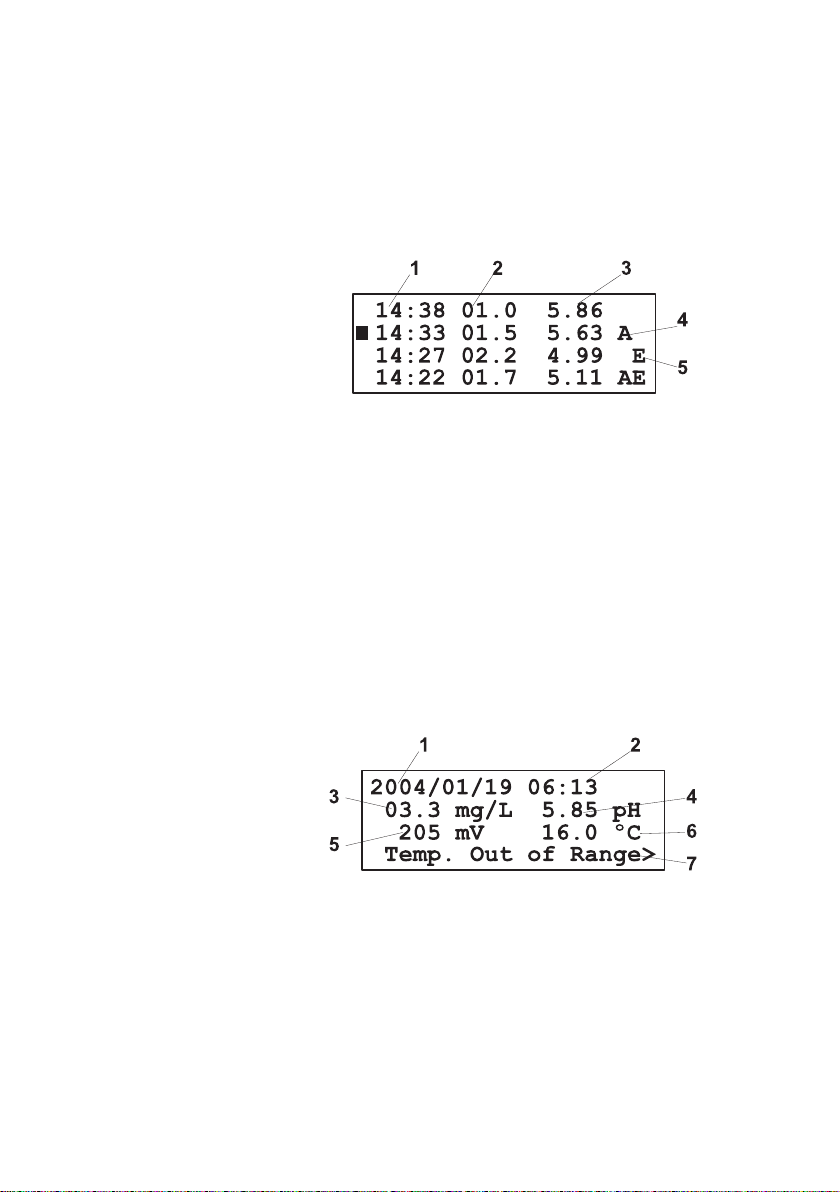
When the searching is in work, the message “Searching
Records” is displayed.
The search result could be:
• “No records found” meaning that no records were found
with specified criteria.
• “No records stored” meaning that there is no record in log.
• Display the log.
The records will have the following structure:
1 – Time of the record
2 – Bromine value
3 – pH value (only for PCA 321 and PCA 331)
4 – Alarm field (empty if no alarms)
5 – Errors field (empty if no errors)
The double arrow sign is present on the bottom line if the log
continues outside the display.
Pressing “UP” or “DOWN” arrow keys, scroll the log with
one record up or down. Pressing longer time one of those
keys will scroll with one page at a time (4 records).
Pressing “CFM” when a record is highlighted, the record
content will be displayed in details.
The display contains:
56
1 – The log day
2 – The log hour and minute
3 – The bromine concentration and units (mg/L)
4 – The pH value and units (pH)
5 – The ORP value and units (mV)
6 – The Temperature value and units (°C or °F)
7 – The Errors and Alarms
Page 57

If many errors or alarms are present, the “<” and “>” signs
RS 485
B
A
I
I
are displayed on the left or right side of the display. Selecting
another message could be done by pressing “LEFT” or
“RIGHT” arrow keys.
Pressing three time “ESC” will return in the main menu.
SERIAL COMMUNICATION
The PCA 311-331 have one RS485 serial communication
port. The serial communication is galvanically isolated from
other analyzer parts.
The connector configuration for RS485 is shown
in the figure aside.
Two mode of working are available for the serial
communication: STANDARD and GSM.
STANDARD MODE
The analyzer could be connected to PC using RS485 to RS232
converter. With the HI 92500 software the analyzer data could
be downloaded to the PC and also the analyzer parameters
could be set from PC.
To set communication as PC type, select “General Menu” “Serial & GSM Comm.” and set the “Type” to STANDARD.
To establish connection with the PC the baud rate, the RS485
address and the password must be matched between the
application and PCA 311-331 analyzer.
The baud rate is set in the “General Menu” - “Serial & GSM
Comm.” - “Baud Rate” menu. Available values are 1200,
2400, 4800, 9600 bps.
Analyzer address is set in the “Address” line and could be
between 0 and 32.
Note: If many analyzers are connected in a RS485 network, each
analyzer must have a unique address.
Note: While one parameter is edited by the user the PC software is
unable to modify it. Any other parameter could be modified by
the PC software.
RS 485
57
Page 58

GSM
GSM MODE
If the “Type” is set to GSM, the analyzer will work with HI 504900
GSM module. This connection enables the analyzer to send
SMSs to one (or two) cellular phone(s) and through this
feature the device can be monitored. Moreover if an error
occurs on the PCA 3x1, a SMS is sent to the cellular phone(s)
signaling immediately the user about the problem.
When the SMS feature is active, three type of SMS messages
are sent to the selected cellular phone(s).
Alarm SMS which contains the Error, Alarm and Warning messages
that are active on the analyzer, separated by ‘;’. The events
that generate the alarm SMS are user selectable from
“General Menu” - “SMS Settings”.
Info SMS which contains the Bromine, pH, ORP and Temperature
readings. Analyzer’s error status and settings are also included
as selected by the user from “General Menu” - “SMS Settings”.
Warning SMS which contains information about the SIM card credit.
The settings related to GSM are grouped in “General Menu”
- “Serial & GSM Comm.”.
SETTING THE GSM FEATURE
To use the SMS feature, a SIM card able to make voice calls
must be used.
It is necessary to enter
the PIN code of the
SIM card inserted in
the GSM module. To
do this, set the
“General Menu” “Serial & GSM
Comm” - “PIN No.”.
Note: The PIN number is not
visible after editing for
protection reasons.
The field will always
show 0000.
Type :STANDARD
Baud Rate:9600
Address: 01
Send SMS :Inactive
PIN No. :0000
Phone 1 :Inactive
No1:--------------Phone 2 :Inactive
No2:---------------
Charge Inf:Inactive
Exp.Date:2010/01/01
Remaining:0000
RepeatNo:2
Delay :05 min
Remote :Active
58
Page 59

Example: if the cellular number is +39123456789 (+39 is the country
GSM CONNECTION
Note: Power the GSM module before first attempt to connect the
Note: If the first attempt to initialize GSM engine fails because of a
One or two phone numbers associated with the service - to
which the messages will be sent – must be set. The number
has to be entered in the fields named “No1” and “No2”. The
space reserved for a phone number is 15 digits.
The phone numbers have to be inserted using the international
format excluding the starting + character and without any space
inside the number.
code), the number to be stored in the PCA 311-331 is
39123456789.
The numbers could be activated or inactivated. The SMS is
sent only to active numbers. If both numbers are inactive, no
SMS is sent even if both numbers are correctly entered. To
activate the phone numbers, set “Active” in the “Phone1” and
“Phone2” fields.
The SMS sending has to be activated by selecting “Active” in
the “Send SMS” field. If “Send SMS” is set to “Inactive” then
no SMS will be sent even if the phone numbers are active.
The number of repeated alarm SMS’s could be set in the field
“RepeatNo”. The range is between 0 and 5. If RepeatNo is set
to 0 than only one SMS is sent.
The delay between two repeated SMSs is set in the “Delay”
item. The range is between 5 and 60 minutes. If the “RepeatNo”
is 0, this parameter has no effect.
After the correct settings are done, the SMS feature can be
enabled by set “General Menu” - “Serial & GSM Comm.” “Type” to GSM.
analyzer to GSM network.
If the PIN number is wrong, then it is not possible to make the
cellular module connection. The “GSM Wrong PIN Code”
message is displayed.
wrong PIN, then no other attempt will be allowed (prevention
of sending three wrong PINs).
To make another attempt, a new PIN has to be entered and
the analyzer has to be restarted. The analyzer attempt to
initialize the GSM module at startup.
59
Page 60
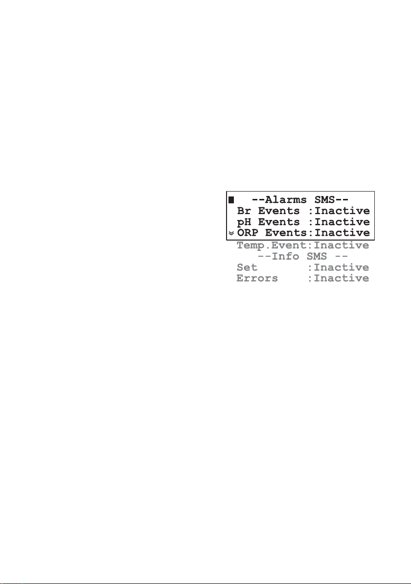
If a wrong PIN was entered three times, the user has to extract
the SIM card and manually enter the PUK number using his
own cellular phone to unlock the SIM card.
Note: There is no need to modify the default baud rate (1200) of the
serial link when enable the GSM feature. It will be switched to
9600 automatically.
SETTING SMS FEATURE
In order to avoid the frequent sending of the SMS’s or rapid
consuming of the GSM credit when one measuring channel
not work correctly, the SMS sending could be customized.
The options are available in the “General Menu” - “SMS
Settings”.
To select the events
that generate alarm
SMS, set the “Br
Events”, “pH Events”,
“ORP Events” or
“Temp. Event” as
Active or Inactive.
When one of them is
active the corresponding alarms and errors will generate an alarm SMS. When
alarm SMS is sent, all current alarms and errors are sent, even
if are not the ones that initiate the SMS.
To customize the info SMS, two options are available:
• “Errors” - when active will include in the info SMS all alarms
and errors currently active on the analyzer.
• “Set” - when active will include in the info SMS alarm and
dosing setpoints.
Alarm SMS
When errors or alarms appears, alarm SMS is sent to the active
phone numbers. Alarm SMS is sent without special request. The
events that generate alarm SMS could be selected as described
in Setting SMS Feature paragraph. Alarm SMS is sent once per
bromine cycle.
At each sending of alarm SMS, after 30 seconds, a phone call is
made by the analyzer to the programmed number(s). This is done
because the SMS can be received with a considerable delay due
to network overload, while the phone call takes place immediately and has a long ring which is more likely to be heard.
60
Page 61

Info SMS
The phone call advises the user that something happened on
the PCA analyzer and SMS is going to be received. Is not
necessary to answer the phone call and it is suggested to
close it without any answer.
A confirmation of the alarm message reception is waited by
the analyzer. The confirmation can be done by simply calling
the PCA analyzer phone number (number of the GSM module).
The analyzer will hang up without answering and will send Info
SMS (this confirmation is managed as an information request;
see further on for details). Info SMS don’t need confirmation.
If “RepeatNo” is more than 0, the instrument sends repeated
(1 to 5 times) alarm messages if confirmation is not received.
This feature prevent losing of the message due for example to overload of the telephone network. The “0” is associated with no repetition: only one message will be sent and no confirmation waited.
The delay (5 to 60 minutes) between two subsequent repeated
messages could be set on the “Delay” line.
Note: A remote connection will cancel the confirmation waiting. Also,
the analyzer events occurred during a remote connection will
not generate any alarm SMS, even after the remote connection ends.
Example of alarm SMS: “Temp Err;L Ph;H Temp;Pwr rst;” (see Errors,
Alarms and Warnings chapter for details)
When the instrument receives a phone call (coming from one
of the programmed cellular numbers), it interprets the calling
as an information request and reacts hanging up and
sending an info SMS.
The maximum number of characters for an SMS is 160, so, if
the message text is longer, many messages will be sent. In this
case a message header is added with informations about the
message type and the current / total number of SMSs (for
example INF1/2: ).
It is possible to ask the PCA 311-331 for Info SMS from a
cellular phone different from the one(s) set in the analyzer.
This is accomplished by sending to the instrument the SMS:
“PxxxxAWE”, where xxxx is the analyzer’s password (the one
used for settings).
The instrument will recognize the command and reply sending
the Info SMS.
61
Page 62

Note: If the analyzer is waiting for confirmation after sending an
Example of info SMS:
Example of info SMS (splitted):
Warning SMS
alarm SMS, the received SMS will be just stored on the SIM
until the confirmation is coming or all the repeated alarm
SMSs are sent.
The info SMS will always contain the Bromine, pH, ORP and
Temperature readings and the Settings and Errors if enabled.
Also, the remaining SMS’s number will be added if “Chk.
Charge” is active.
“Temp Err;L Ph;H Temp; READINGS:
ReagRem=8413;Br=2.0;
pH=7.02;Orp=700;Temp=25.2;”
“INF1/2: Temp Err;L Br;L Ph;H Temp;Br Cal;SET: Br(SP=2.00;
AIH=2.70;AIL=150);pH(SP=7.00;AIH=8.00;AIL=6.00);ORP
(AIH=800; AIL=200);Temp(AIH=30.0;AIL=20.0);”
“INF2/2: READINGS: ReagRem=8413;Br=1.35;pH=5.02;
ORP=280; Temp=75.0; Remaining SMS=321;”
The information about SIM charge and expiration date are
not saved in the SIM card but are managed by the network
operator; the analyzer can not get directly the information.
To prevent an unnoticed discharge of the SIM card, the user
has to configure manually (accordingly with the credit stored
on the SIM card), the maximum number of SMS’s that can be
sent. The item is “Remaining” (SMS) in the “General Menu” “Serial & GSM com.” menu.
If the “General Menu” - “Serial & GSM com.” - “Charge
Inf”is set “Active”, every time an SMS is submitted, the
“Remaining” item is updated and will always indicate the
remaining number of messages that the analyzer can send.
With “Chk.Charge” set “Active”, the number of remaining SMS is
checked and when is going to reach zero, a warning SMS containing the text “Maximum number of SMS
reached. Please check
the cellular SIM card
charge level” is sent.
Charge Inf:Active
Exp.Date:2010/01/01
Remaining:0000
RepeatNo:2
62
Page 63

This particular situation is managed as an error occurrence
and a confirmation of the SMS reception is waited. After that,
a “GSM no credit” warning appears on the display signaling
that no other SMS can be sent.
In this case the user is supposed to extract the SIM card from
the cellular module as soon as possible and check the
remaining credit (using its own cellular phone and calling the
network operator).
Every time a recharge of the cellular module SIM card is
performed, the corresponding expiration date has to be
manually updated – item “Exp.Date” in the “General Menu”
- “Serial & GSM com.”.
If the “Chk.Charge” item is set “Active”, a check is performed
daily between the current date and the expiration date. Two
weeks before the expiration date, the warning SMS “The cellular SIM card will expire on: DD-MM-YYYY. Please recharge or
substitute it” is sent to the programmed phone number(s). The
same message will be sent again also one week before, and
the day before the expiration date.
Note: This particular warning message does not need confirmation.
In this case the user has to recharge or substitute the SIM
card. The sending of the repeated warning messages will be
reset when the expiration date is changed. If the expiration
date is reached without any updating of the expired date, then
the message “GSM Card expired” appears on the display
and no more SMS’s will be sent by the analyzer until the error
is deactivated.
To deactivate this error it is necessary to update the SIM
expiration date.
If the user has unlimited credit on the SIM card, the “Chk.
Charge” must be set “Inactive”. In this case the value of
remaining messages will not be decremented and no check
will be performed on the SIM card expiration date. Moreover,
in the info SMS will not be present the remaining-messages
information.
Note: If a problem related to GSM feature occurs during the normal
functioning of the analyzer, the “GSM Not Respond”, “GSM
Init failed” or “GSM Network Error” will be displayed and the
analyzer will try repeatedly to initialize the cellular engine. The
error will be deactivated only after a successful initialization.
63
Page 64

MODEM CONNECTION
Note: If the PC stops the communication for 4 minutes, the GSM
Modem connection can be established between PCA 311331 and a remote computer. The connection allows the user
to interrogate the analyzer, from remote position, about its
status and measurements and to change analyzer parameters.
Also the log could be downloaded through remote connection.
A SIM card able to receive data calls must be used in HI 504900
GSM module.
To enable the answer
to data request, the
item “Remote” from
“General Menu” “Serial & GSM com.”
must be set “Active”.
To make the data transfer between PCA 311-331 and remote
PC, HI 92500 software must be installed on the PC, and modem must be connected between PC and phone line.
The baud rate, the password and the RS485 address must the
same on PCA and on PC application.
call is interrupted by the analyzer to free the line.
Remaining:0000
RepeatNo:2
Delay :05 min
Remote :Active
64
Page 65

MAINTENANCE
The PCA 311, PCA 321 and PCA 331 analyzers incorporate
several technologies to minimize the maintenance.
Also, if the GSM module is connected, the warnings, alarms
and errors are sent to the operator, making the maintenance
even simpler.
The analyzer status could be sent via SMS messages after a
call from operator.
Calibration of the bromine measuring circuits is not normally
required. The DPD technique for measuring bromine
concentration is well established and consistent. Also,
by measuring the sample blank absorbency to establish the
zero reference with each measurement, the accuracy of the
analyzer is assured.
If, for any reason, the Bromine measurements are inaccurate
proceed with the calibration procedure.
A visual check of the hydraulic compartment can detect leaks,
pump tubing fatigue or breakage. These periodic checks help
ensure reliable analyzer performance.
PCA 311-331 analyzers warning the user when the reagents level
reaches approximately 20% with the “Low reagent” message.
Working at maximum capacity (3 minutes sampling rate), the
analyzers can operate for 1.5 more days.
The alarm system is based on an internal counter that has to
be reset every time the reagents are replaced.
The counter keeps track of the number of measurements taken
and informs the user when it reaches the 16000th sample with
the message “No reagent”.
The pH, ORP and Temperature measurements are done with
standard techniques that assure reliability and accuracy.
However if a problem occurs on those measuring channels,
an SMS is sent to the user.
Furthermore, if the relation between bromine, pH and ORP is
known for a certain application, one of those readings could
be used to check the others, for example check the bromine
and pH by reading the ORP values.
65
Page 66

ELECTRODE CONDITIONING AND MAINTENANCE
Preparation
Remove the probe protective cap.
DO NOT BE ALARMED IF ANY SALT DEPOSITS ARE PRESENT.
This is normal with probes and they will disappear when rinsed
with water.
During transport tiny bubbles of air may have formed inside
the glass bulb. The probe cannot function properly under
these conditions. These bubbles can be removed by “shaking
down” the probe as you would do with a glass thermometer.
If the bulb and/or junction are dry, soak the probe in
HI 70300 Storage Solution for at least one hour.
If the probe does not respond to pH changes, electronics may
be down and the electrode should be replaced.
Test measurement
Rinse the probe tip with distilled water.
Immerse the probe in the Hanna pH buffer 7.01 (HI 7007)
until the solution is in contact with the metal ring and stirr
gently for 30 seconds. The reading must be near 7.01 pH.
Repeat the operation for pH 4.01 solution (HI 7004).
The difference from the previous reading must be near 3 pH
Storage
Note: Never store the probe in distilled or deionized water.
Periodic maintenance
66
To minimize clogging and assure a quick response time, the
glass bulb and the junction should be kept moist and not
allowed to dry out. This can be achieved by installing the
input lines in such way that the probe holder is kept filled with
sample.
When not in use, for longer time, dismount the probe and keep
in the protective cap with a few drops of HI 70300 Storage
Solution or, in its absence, HI 7082 (KCl 3.5 M Solution).
Follow the Preparation Procedure above before remount the probes.
Inspect the probe and the cable. The cable used for the connection must be intact and there must be no points of broken
insulation on the cable or cracks on the probe stem or bulb.
Page 67

Cleaning procedure
IMPORTANT: After performing any of the cleaning procedures rinse the probe
Troubleshooting
General Soak in Hanna HI 7061 General Cleaning
Solution for approximately ½ hour.
Removal of films, dirt or deposits on the membrane/junction:
Protein Soak in Hanna HI 7073 Protein Cleaning
Solution for 15 minutes.
Inorganic Soak in Hanna HI 7074 Inorganic Cleaning
Solution for 15 minutes.
Oil/grease Rinse with Hanna HI 7077 Oil and Fat
Cleaning Solution.
thoroughly with distilled water and soak the electrode in HI 70300
Storage Solution for at least 1 hour before reinstalling it.
Evaluate your probe performance based on the following.
• Noise (Readings fluctuate up and down) could be due to
clogged or dirty junction: refer to the Cleaning Procedure
above.
•Dry Membrane/Junction: soak in Storage Solution HI 70300
for at least 1 hour. Check to make sure the installation is
such as to create a well for the probe bulb to constantly
remain moist.
•Drifting: soak the probe tip in warm Hanna Solution
HI 7082 for one hour and rinse tip with distilled water.
•Low Slope: refer to the cleaning procedure above.
• No Slope:
- Check the probe for cracks in glass stem or bulb (replace
the probe if cracks are found).
- Make sure cable and connections are not damaged.
• Slow Response/Excessive Drift: soak the tip in Hanna
Solution HI 7061 for 30 minutes, rinse thoroughly in distilled
water and then follow the Cleaning Procedure above.
•For ORP probe: polish the metal tip with a lightly abrasive
paper (paying attention not to scratch the surface) and wash
thoroughly with water.
67
Page 68

CHANGING PERISTALTIC PUMP TUBING
It is recommended that the peristaltic pump tubes be changed on
a regular basis depending on sampling period and operating
time.
For a 5 minutes sample interval and continuous operation,
changing of the tubes every month is recommended. For best
results however, change the tubings every time the reagents are
replaced.
Note: Rubber gloves and eye protection must be worn while
handling reagent tubing to prevent contact with reagent
chemicals. Read MSDS documents before proceeding.
Grasp the plastic collar of one pump tube and pull the fitting
away from the pump toward the front of the case until it clears
the retaining indentation.
Then move the fitting sideways from the pump until the tube
clears the slot.
Release the tube and fitting. The fitting on the other end of the
pump tube may now be easily removed from the pump body.
68
Remove the reagent tubing from one end of the pump tube
fitting and pull the pump tube from behind the pump rollers.
Replace the pump tube with a new one and reassemble in
reverse order. Repeat for the other pump tube.
Page 69

HI 70479
HI 70473
HI 70474 or HI 70475
TUBING REPLACEMENT
The remaining tubing in the analyzers should be replaced
every two months.
When installing new tubing it is helpful to dip them in hot
water before making the connections.
It is also recommended that one tube at a time is removed
and replaced.
Note: DPD reagent tubing may darken before the scheduled replacement
time, but this will not affect the instruments performance.
CLEANING MEASUREMENT CELL
In order to maintain the maximum reliability of measurements,
it is recommended to periodically clean the measurement cell.
In fact, the measurement cell could collect sediment or
develop a film growth on the inside walls. When the automatic
dirt compensation system detect the deposits presence, the
analyzer will show “Dirty cell” message.
The measurement could continue but cleaning is recommended
to avoid deposits that are harder to clean.
Thorough cleaning with a dilute acid solution and a cotton
swab is recommended monthly. Depending on sample
conditions at individual locations and absence of input filters,
it may be necessary to clean the cell on a weekly basis. This
can be determined by observing the cell condition when
reagents are changed.
It is also highly recommended to clean the cell every time you
turn the meter off. In such a way, scaling and molds growth
are prevented. Otherwise, subsequent cleaning might become
more difficult.
For cleaning procedure, remove the plastic cap placed on the
top of the measuring cell.
Add a few drops of 19.2N Sulfuric Acid solution or alcohol to the cell.
69
Page 70

Allow sulfuric acid to stand in the measuring cell for 15 minutes
to dissolve any foreign materials adhering to the cell walls. Wipe
the cell interior with a cotton-tipped swab. After wiping, open
the drain port to empty the measuring cell from the cleaning
solution.
CHANGING MEASURMENT CELL
To change the measuring cell (#7 page 10) with a new one
(HI 70487) in the PCA 311 - 331 analyzers, follow the steps:
• Stop the analyser by turning off the main switch.
• Remove the reagent and buffer bottles to free space.
• Disconnect the reagent and buffer tubes from the cell
body.
• Disconnect the sample inlet tube from the cell body. This
tube is between electrovalve (#21 pag 10) and cell.
• Disconnect the drain tube (#8 on page 10) from the cell.
• Unplug the cell connector.
• Unscrew the cell from its support by using hexagonal
wrench.
• Put the new cell in its place and screw it in position. Take
care to position the electrical cable first.
• Reconnect the electrical wires and the pneumatic circuit
as it was at the dismounted cell.
• Power on the PCA 311 - 331 analyzer.
• Go to menu mode “Bromine Menu” - “Cal measuring
Cell” and start the “Calibration Blank” function.
• Confirm by pressing “CFM” when asked “Start the blank
calibration?”.
• Wait for the end of the procedure.
• If the message Press CFM appears, the procedure was
successful and Pressing “CFM” will save the coeficients
for the new cell.
• If the message “failed” appears, the cell is not working
properly. Check the electrical cable connection and if the
error persist call Hanna Service.
• Prime the reagent pump - see page 36 for details.
• Wait 3 cycles for the measurement to stabilize.
• Calibrate the measuring cell as described at page 40.
Note: Before start measuring assure that a stirring bar (HI 70487)
is present in the cell.
70
Page 71

ERRORS, ALARMS AND WARNINGS
The possible error, alarm and warning messages are described
below with a short suggestion about the needed action to
remove the error.
The pH and temperature related messages are present only on
PCA 321 and PCA 331 and the ORP related messages are
present only on PCA 331.
The warning messages appears on LCD and some of them on
SMS. The measuring is not stopped on warnings.
Alarm conditions generate messages on the LCD, send SMS
(if enabled), activate the alarm relay and the ALARM LED.
Error conditions generate messages on the LCD, send SMS (if
enabled), activate the system error relay, the SYSTEM ERROR
LED and block the dosing.
ERROR MESSAGES
“No Reagent” on LCD and “No Reag.” on SMS
The reagent counter reached 0.
Change the reagent bottle and reset the reagent counter
“Hardware Error” on LCD and “Hw Err” on SMS
Error on the hardware.
Call Hanna service.
“Detector Error” on LCD and “Det Err” on SMS
The light source or light detector not working or the
detector is too dirty, the reading is under “Low Point” value.
Clean cell, replace the cell, observe if the sample flow in
the cell, edit the “Low Point” value.
“pH Out of Range” on LCD and “pH Err” on SMS
pH value is outside range (0.00 to 14.00 pH).
Change the pH probe.
“ORP Out of range.” on LCD and “ORP Err” on SMS
ORP value is outside range (0 to 2000 mV).
Change the ORP probe, verify the sample ORP
“Temp. Out of Range” on LCD and “Temp Err” on SMS
Temperature value is outside range (5.0 to 75.0 °C).
Change the pH probe, verify the sample temperature, verify
the pH probe connector.
71
Page 72

ALARM MESSAGES
WARNING MESSAGES
“Conc. Out of Range” on LCD and “Br Err” on SMS
Bromine value is outside range (0.0 to 10.0 mg/L).
The bromine concentration is too high.
“High Bromine” on LCD and “H Br” on SMS
The concentration is over the Alarm High setpoint.
Change the setpoint.
“Low Bromine” on LCD and “L Br” on SMS
The concentration is under the Alarm Low setpoint.
Change the setpoint, verify the bromine dosing, wait for
PCA to adjust the value.
“High pH” on LCD and “H pH” on SMS
The pH is over the Alarm High setpoint.
Change the setpoint, verify the pH dosing, wait for PCA to
stabilize the value.
“Low pH” on LCD and “L pH” on SMS
The pH is under the Alarm Low setpoint.
Change the setpoint, verify the pH dosing, wait for PCA to
adjust the value.
“High ORP” on LCD and “H ORP” on SMS
The ORP is over the Alarm High setpoint.
Change the setpoint, verify the ORP probe.
“Low ORP” on LCD and “L ORP” on SMS
The ORP is under the Alarm Low setpoint.
Change the setpoint, verify the ORP probe.
“High Temperature” on LCD and “H Temp” on SMS
The Temperature is over the Alarm High setpoint.
Change the setpoint, verify the pH probe.
“Low Temperature” on LCD and “L Temp” on SMS
The Temperature is under the Alarm Low setpoint.
Change the setpoint, verify the pH probe.
“Dirty Cell” on LCD and “Drt Cell” on SMS
The light level is too low.
Clean the cell.
72
Page 73

“Reagent Low Level” on LCD and “L Reag” on SMS
The reagent reach the 20% of the initial quantity.
Change the reagent or reset the reagent counter.
“Br Calibration Old” on LCD and “Br Cal” on SMS
Cell calibration is older than 1 months.
Calibrate the cell.
“Reagent Expired” on LCD and “Reag Exp” on SMS
Reagent is older than 3 month.
Change the reagent and reset the reagent counter.
“GSM Wrong PIN Code”: appears on LCD
Wrong PIN code was entered.
Set the correct pin code and restart the analyzer.
“GSM Init failed”: appears on LCD
The GSM modem was not successfully initialized.
Wait for auto retry. Verify other messages related to GSM.
“GSM Card Expired”: appears on LCD
The SIM expiration date is reached.
Recharge the SIM card and change the expiration date or
set the “Chk. Charge” inactive.
“GSM No Credit”: appears on LCD
The number of remaining SMS is 0.
Recharge the SIM card and change the “Remaining” SMS
value, or set the “Chk.Charge” inactive.
“GSM Not Respond”: appears on LCD
The GSM modem not respond.
Check the data cable between GSM module and PCA,
check the GSM module power supply and wait for auto
retry.
“GSM Network Error”: appears on LCD
The GSM network not respond.
Check the GSM module antenna and wait for auto retry.
“Pwr rst”: appears on SMS
There was a reset on the analyzer.
Check the main power supply for the cause of dropout.
73
Page 74

“pH calibration Old” on LCD and “pH Cal” on SMS
The pH calibration is older than 1 months.
Calibrate the pH probe.
“No pH Calibration” appears on LCD
The pH channel was not calibrated.
Appears after “Set Default pH Cal.” or after EEPROM
error. In the last case, call Hanna service.
“No ORP Calibration” on LCD and “No ORP Cal” on SMS
The ORP channel was not calibrated.
Appears after EEPROM error. Call Hanna service.
“No Temp. Cal” on LCD and “No T Cal” on SMS
The Temperature channel was not calibrated.
Appears after EEPROM error. Call Hanna service.
ACCESORIES
ChecktempC Thermometer (-50.0 to 150.0 ºC)
pHep5 pH meter (0.00 to 14.00 pH)
ORP ORP tester (+/-999 mV)
HI 1005 pH/temperature process probe
HI 2008 ORP process probe
HI 504900 GSM transmitter
HI 704731 Complete set of tubes from pressure regulator to drain PCA 311
HI 704732 Complete set of tubes from electrode holder to drain PCA 321-331
HI 70474 Peristaltic pump tube (6 pcs)
HI 70475 Peristaltic pump tube (2 pcs)
HI 70476 Reagent bottle inside tube (6 pcs)
HI 70477 Y strainer and the tube from Y strainer to cell (6 pcs)
HI 70478 Tube from bottle to pump (6 pcs)
HI 70479 Tube from pump to Y strainer (6 pcs)
HI 70482 0.5/50 micron filter system
HI 70483 Complete kit of reagent tubing spare kit (2 pcs)
HI 70484 Complete kit of reagent tubing spare kit (6 pcs)
HI 70485 Cuvet stirrer motor
HI 70486 Stirring bar (5 pcs)
HI 70487 Colorimetric cell
HI 70488 Electrovalve (24VAC/60Hz)
HI 70489 Electrovalve (24VAC/50Hz)
HI 70492 Electrode holder PCA 331
HI 70493 Closing cap for electrode holder
74
Page 75

HI 70494 Calibration port tap
HI 70496 Replacement filter 0.45um (1pcs)
HI 70497 Replacement filter 50um (1pcs)
HI 70498 Bromine Reagent Pack (HI 70498A, HI 70498B, HI 70452)
pH Solutions
HI 7004M or HI 7004L pH 4.01 Buffer Solution, 230 or 500 mL bottle
HI 7006M or HI 7006L pH 6.86 Buffer Solution, 230 or 500 mL bottle
HI 7007M or HI 7007L pH 7.01 Buffer Solution, 230 or 500 mL bottle
HI 7009M or HI 7009L pH 9.18 Buffer Solution, 230 or 500 mL bottle
HI 7010M or HI 7010L pH 10.01 Buffer Solution, 230 or 500 mL bottle
ORP Solutions
HI 7020M or HI 7020L 200-275mV Buffer Solution, 230 or 500 mL bottle
HI 7091M or HI 7091L Pretreatment Reducing Solution, 230 or 460 mL bottle
HI 7092M or HI 7092L Pretreatment Oxidizing Solution, 230 or 460 mL bottle
Electrode Storage Solutions
HI 70300M or HI 70300L Storage Solution, 230 or 460 mL bottle
HI 7082 3.5M KCl Electrolyte, 4x50 mL
Electrode Cleaning Solutions
HI 7061M or HI 7061L General Cleaning Solution, 230 or 460 mL bottle
HI 7073M or HI 7073L Protein Cleaning Solution, 230 or 460 mL bottle
HI 7074M or HI 7074L Inorganic Cleaning Solution, 230 or 460 mL bottle
HI 7077M or HI 7077L Oil & Fat Cleaning Solution, 230 or 460 mL bottle
HI 92500 Windows Compatible Application Software
Hanna Instruments reserves the right to modify the design, construction and appearance
of its products without advance notice.
75
Page 76

TECHNICAL SERVICE CONTACTS
Australia:
Tel.(03)9769.0666 • Fax (03)9769.0699 e-mail:hannains@hannainst.com.au
China:
Tel. (10)88570068 • Fax (10)88570060 e-mail: hannachina@vip.sina.com
Egypt:
Tel. & Fax (02)2758683 e-mail: hannaegypt@go.com.eg
Germany:
Tel. (07851)9129.0 • Fax (07851)9129.99 e-mail: hannager@aol.com
Greece:
Tel. (210)823.5192 • Fax (210)884.0210 e-mail: hannagr@otenet.gr
Indonesia:
Tel. (21)4584.2941 • Fax (21)4584.2942 e-mail: transit@dnet.net.id
Japan:
Tel. (03)3258.9565 • Fax (03)3258.9567 e-mail: sales@hanna.co.jp
Korea:
Tel. (02)2278.5147 • Fax (02)2264.1729 e-mail: mccoyhan@chollian.net
Malaysia:
Tel. (603)5638.9940 • Fax (603)5638.9829 e-mail: hannamal@tm.net.my
Singapore:
Tel. 6296.7118 • Fax 6291.6906 e-mail: hannaap@pacific.net.sg
South Africa:
Tel. (011)615.6077 • Fax (011)615.8582 e-mail: hannasa@mweb.co.za
United Kingdom:
Tel. (01525)850.855 • Fax (01525)853.668 e-mail: salesteam@hannainst.co.uk
USA:
Tel. (401)765.7500 • Fax (401)765.7575 e-mail: sales@hannainst.com
For additional technical support in your local language see www.hannainst.com
76
MAN331
05/05
 Loading...