

Page 1
Instruction Manual
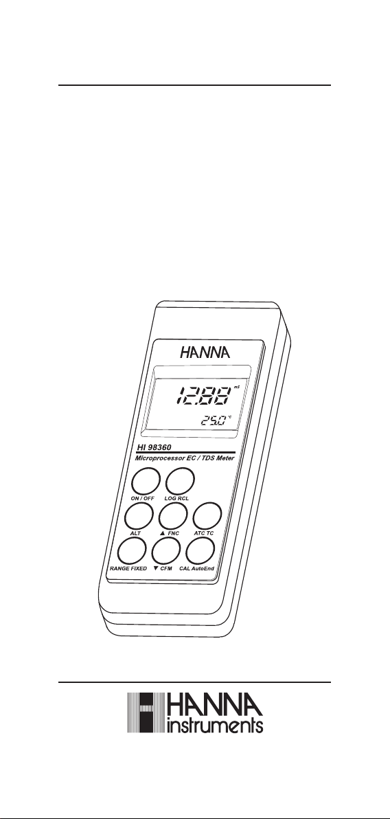
HI 98360
Autoranging & Logging
Portable Waterproof
Microprocessor
EC/TDS/NaCl/°C Meter
www.hannainst.com
Page 2

Dear Customer,
Thank you for choosing a Hanna Instruments product.
Please read this instruction manual carefully before using the instrument.
This manual will provide you with the necessary information for correct
use of the instrument, as well as a precise idea of its versatility.
If you need additional technical information, do not hesitate to e-mail
us at tech@hannainst.com or turn to the back cover for our
worldwide contact list.
This instrument is in compliance with directives.
WARRANTYWARRANTY
WARRANTY
WARRANTYWARRANTY
HI 98360 is guaranteed for two years against defects in workmanship
and materials when used for its intended purpose and maintained
according to instructions. Electrodes and probes are guaranteed for six
months. This warranty is limited to repair or replacement free of charge.
Damage due to accidents, misuse, tampering or lack of prescribed
maintenance is not covered.
If service is required, contact the dealer from whom you purchased the
instruments. If under warranty, report the model number, date of
purchase, serial number and the nature of the problem. If the repair
is not covered by the warranty, you will be notified of the charges
incurred. If the instrument is to be returned to Hanna Instruments,
first obtain a Returned Goods Authorization number from the Technical Service department and then send it with shipping costs prepaid.
When shipping any instrument, make sure it is properly packed for
complete protection.
TABLE OF CONTENTSTABLE OF CONTENTS
TABLE OF CONTENTS
TABLE OF CONTENTSTABLE OF CONTENTS
WARRANTY ............................................................................................. 2
PRELIMINARY EXAMINATION ...................................................................... 3
GENERAL DESCRIPTION ............................................................................ 3
FUNCTIONAL DESCRIPTION ........................................................................ 4
SPECIFICATIONS ....................................................................................... 5
CONNECTIONS ......................................................................................... 5
SETUP .................................................................................................... 7
TAKING MEASUREMENTS .......................................................................... 9
AUTORANGING ...................................................................................... 10
AUTO ENDPOINT MODE .......................................................................... 10
TEMPERATURE COMPENSATION ............................................................... 11
EC/TDS CALIBRATION ............................................................................. 12
NaCl CALIBRATION ................................................................................. 13
TEMPERATURE CALIBRATION (for technical personnel only) .......................... 13
TEMPERATURE ADJUSTMENT .................................................................. 14
LOGGING FUNCTION ............................................................................... 15
DATA TRANSFER TO PC ........................................................................... 1 8
BATTERY REPLACEMENT ......................................................................... 19
PROBE MAINTENANCE ............................................................................ 19
CONDUCTIVITY VS. TEMPERATURE CHART ................................................ 2 0
ACCESSORIES ........................................................................................ 21
2
Page 3

PRELIMINARY EXAMINATIONPRELIMINARY EXAMINATION
PRELIMINARY EXAMINATION
PRELIMINARY EXAMINATIONPRELIMINARY EXAMINATION
Remove the instrument from the packing material and examine it
carefully to make sure that no damage has occurred during shipping.
If there is any damage, notify your dealer or the nearest Hanna
Customer Service Center.
Each instrument is supplied with:
• HI 76309/1.5 Conductivity/TDS probe with 1.5 m cable
• 1.5V, AA size Alkaline Batteries (4 pcs)
• Instruction Manual
• Rugged Carrying Case
Note: Save all packing material until you are sure that the instrument
functions correctly. All defective items must be returned in the
original packing with the supplied accessories.
GENERAL DESCRIPTIONGENERAL DESCRIPTION
GENERAL DESCRIPTION
GENERAL DESCRIPTIONGENERAL DESCRIPTION
HI 98360 is a waterproof portable logging microprocessor-based Conductivity/TDS/NaCl/Temperature meter.
The autoranging feature of the EC and TDS ranges automatically sets
the meter to the scale with the highest possible resolution.
The Auto Endpoint feature automatically freezes the display when a
stable reading is reached.
The measurements are automatically (ATC) or manually (MTC) compensated for temperature. The temperature coefficient value is user
selectable. It is possible to disable the temperature compensation and
measure the uncompensated conductivity.
The Battery Error Prevention System (BEPS) turns the meter off when
the batteries level is too low to ensure reliable readings.
The meter can store data in memory at the user’s request for later
retrieval.
HI 98360 also allows data transfer to computer through the RS232
port.
3
Page 4

FUNCTIONAL DESCRIPTIONFUNCTIONAL DESCRIPTION
FUNCTIONAL DESCRIPTION
FUNCTIONAL DESCRIPTIONFUNCTIONAL DESCRIPTION
1) Power adapter socket.
2) RS232 serial communication connector.
3) DIN electrode connector.
4) Liquid Crystal Display (LCD).
5) ON/OFF key, to turn the meter on and off.
6) ALT key, to enable alternate key function.
7) RANGE FIXED key, to select measurement range or (with ALT) to
freeze the current range on the LCD.
8) CAL AutoEnd key, to enter calibration mode or (with ALT) to
enter Auto Endpoint mode.
9) CFM key, to move down or (with ALT) confirm values.
10) ATC TC key, to select temperature compensation mode or (with
ALT) to view the temperature coefficient value.
11) FNC key, to move up or (with ALT) enter setup mode.
12) LOG RCL key, to store or (with ALT) recall measurements.
4
Page 5

SPECIFICATIONSSPECIFICATIONS
SPECIFICATIONS
SPECIFICATIONSSPECIFICATIONS
SPECIFICATIONS
RA EGN
NOITULOSER
YCARUCCA
Fº86/Cº02@
noitarbilaCCE
99.92ot00.0
9.992ot0.03
9992ot003
cnu
l/g0.004otpudetasnepmo
µ
10.0
1.0
µ
µ
mc/S
1
mpp10.0
mpp1.0
mpp1
l/g1.0
Cº1.0
± gnidaerfo%5.0
± gnid
± gnidaerfo%5.0
± Cº4.0
µ
3141,0.48
µ
mc/S
µ
mc/S
µ
mc/S
mc/Sm99.92ot00.3
mc/Sm0.002ot0.03
)*(
detasnepmocnumc/Sm0.005otpu
ytivitcudnoc
mpp99.41ot00.0
mpp9.941ot0.51
mpp9941ot051
l/g99.41ot05.1
l/g0.001ot0.51
)*(
SDT
)rotcaf08.0htiw(
lCaN%0.004ot0.0
Cº0.021ot9.9–
mc/S
mc/S
mc/Sm10.0
mc/Sm1.0
l/g10.0
lCaN%1.0
aerfo%5.0
:elbaliavasreffub6htiwtniop1
mc/S
mc/Sm8.111,0.08,88.21,00.5
(*)
Uncompensated conductivity (or TDS) is the conductivity (or TDS) value without
temperature compensation.
5
Page 6
SPECIFICATIONS (SPECIFICATIONS (
SPECIFICATIONS (
SPECIFICATIONS (SPECIFICATIONS (
cont.cont.
cont.
cont.cont.
))
)
))
A5.1x4
htiwtniop1 7307IH reffub
.9–
Erof(
)lanoitpo(
morfcitamotuArolaunaM
Cº0.021ot9
erusaemotdelbasidebnac(
)ytivitcudnocdetasnepmocnu
Cº/%00.6ot00.0
;)ylnoSDTdnaC
Cº/%09.1sieulavtluafed
08.0ot04.0
)05.0sieulavtluafed(
setunim5retfA
)delbasidebnac(
esufosruoh002.xorppa-
retpadaCDV21ro
)Fº221–23(Cº05–0
%001HRxam
noitarbilaClCaN
erutarepmeT
noitasnepmoc
tneiciffeocerutarepmeT
erutarepmetecnerefeRCº52roCº02
rotcafSDT
eborP)d
ffo-otuA
ylppusrewoP
snoisnemiD)”4.2x1.3x7.7(mm06x08x691
thgieW)zo81(g005
tnemnorivnE
ytnarraWsraey2
edulcni(eborpCE5.1/90367IH
)dedulcni(seirettabenilaklaA
CONNECTIONSCONNECTIONS
CONNECTIONS
CONNECTIONSCONNECTIONS
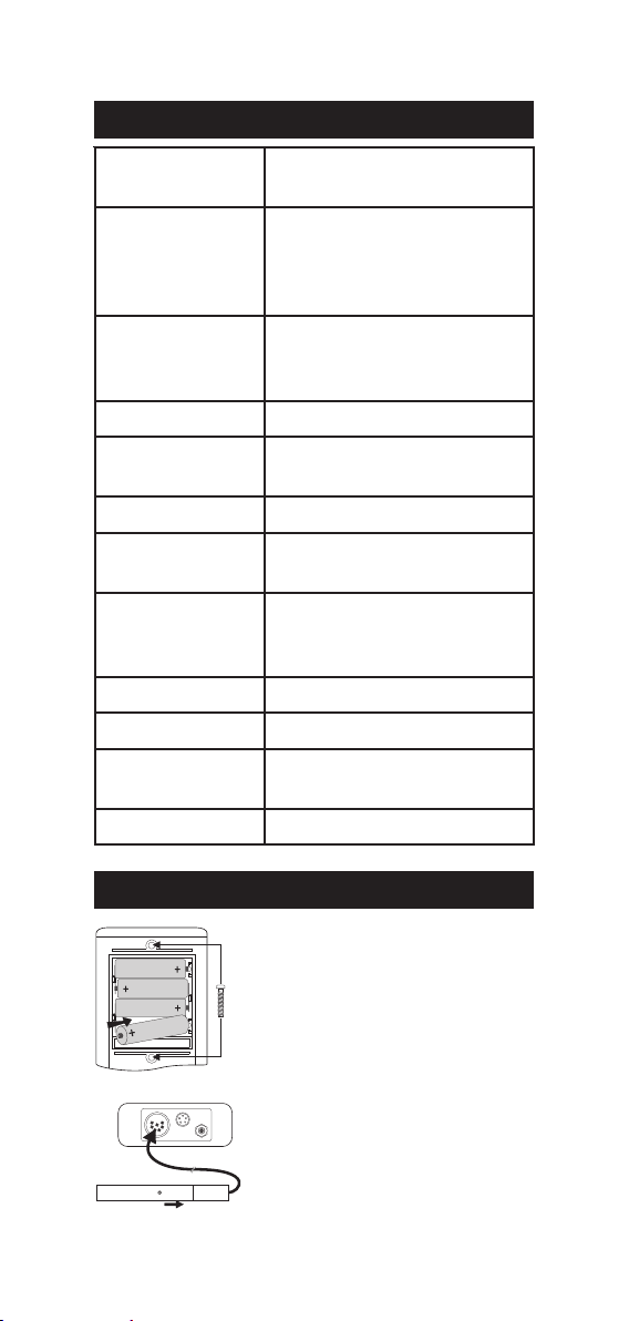
Remove the back cover, unwrap the batteries
and install them while paying attention to
the polarity. Replace the back cover.
Alternatively, connect the voltage adapter
to the power adapter socket.
Connect the EC/TDS probe to the 7-pin
connector located on the top of the instrument.
Tighten the threaded ring.
Make sure the probe sleeve is properly
inserted, as shown in the nearby figure.
6
Page 7
SETUPSETUP
SETUP
SETUPSETUP
Setup is used to view or change the instrument parameters.
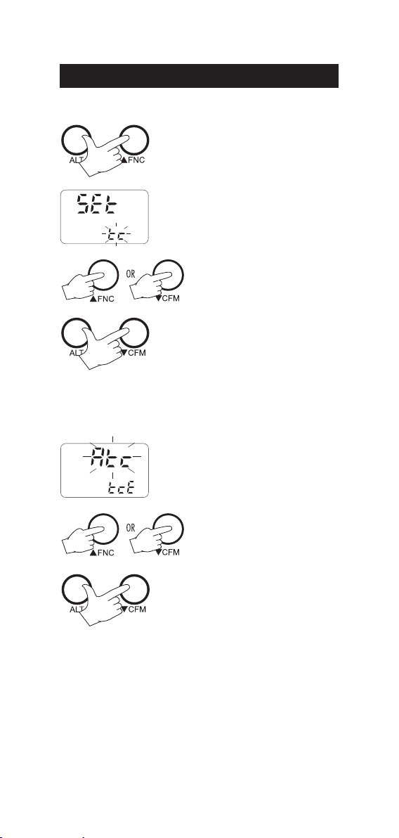
To enter setup press ALT+FNC when the
meter is in measurement mode.
"Set" is displayed on the upper LCD. The
lower LCD displays the blinking code of the
current setup item.
Select the desired setup item using
the or key.
Press ALT+CFM to confirm.
Note: If ALT+FNC are pressed before item confirmation, the meter
will escape and return to measurement mode.
Once the desired setup item has been
selected, its current value blinks (if it is a
changeable parameter).
To change the value use the or
key.
Press ALT+CFM to confirm.
Note: Press ALT+FNC before confirmation to escape without changing
the previously set value.
The following table lists the setup items, their valid range of values
and the factory settings (default):
7
Page 8

Item Description Valid values Default
tc Temp. compensation coeff. 0.00 to 6.00 %/°C 1.90
tcE Temp. compensation mode Atc, Mtc, notc Atc
rEF Reference Temperature 20 or 25°C 25°C
tdS TDS factor 0.40 to 0.80 0.50
CEL Cell constant (K) 0.500 to 1.700 1.000
Aof Auto-Off enable On, OFF On
YEA Year 1999 to 2098 1999
dAT Date dd:mm 01:01
hou Hour hh:mm 00:00
uEr Firmware release
Chr Battery level test
Notes:
• Once enabled, the Auto Off time is fixed at 5 minutes.
• When the battery level test is selected (Chr), LCD will display
the remaining percentage of battery charge. 100% means
fully charged battery and 0% corresponds to the minimum
battery level that allows the meter to operate.
The battery charge level calculation is based on a typical
alkaline battery discharge curve.
If the meter is connected to an external power adapter and
"Chr" is selected, the LCD will display "LINE".
• At startup, the main LCD shows briefly the reference temperature, while the secondary LCD shows "rEF".
8
Page 9

TAKING MEASUREMENTSTAKING MEASUREMENTS
TAKING MEASUREMENTS
TAKING MEASUREMENTSTAKING MEASUREMENTS
Press the ON/OFF key to turn the meter on.
At startup the display will show the reference
temperature value with "rEF" indication for a few
seconds.
Immerse the probe into the solution to be tested.
The sleeve holes must be completely submerged.
Tap the probe repeatedly to remove any air bubbles
that may be trapped inside the sleeve.
If needed, press the RANGE key repeatedly
until the desired range (EC, TDS, NaCl) is
selected on the LCD.
Allow for the reading to stabilize. The upper
LCD displays the measure in the selected range
while the temperature is displayed on the lower
LCD.
Notes:
• If the meter displays "----", the reading is out of range.
• If the reading is not stable, the stability indicator " " blinks.
• Make sure the meter is calibrated before taking measurements.
• If measurements are taken successively in different samples, to
have accurate readings it is recommended to rinse the probe
thoroughly with deionized water before immersion in the samples.
• To maximize battery life, the meter is automatically switched off
after 5 minutes of non-use. To reactivate the instrument press the
ON/OFF key. This feature can be disabled by entering the setup
mode and selecting the "AoF" item (see SETUP section for details).
• TDS reading is obtained multiplying the EC reading by the TDS
factor, which has a default value of 0.50. It is possible to change
the TDS factor in the 0.40 to 0.80 range by entering the setup
mode and selecting the "tdS" item (see SETUP section). Always set
the reference temperature to 25°C when measuring TDS.
• When the use of an alternate function (RCL, FNC, CFM, FIXED,
TC and AutoEnd) is requested, press and hold the ALT key first
and then the second key.
9
Page 10

AUTORANGINGAUTORANGING
AUTORANGING
AUTORANGINGAUTORANGING
The EC and TDS scales are autoranging. The meter automatically sets
the scale with the highest possible resolution.
By pressing ALT+FIXED, the autoranging
feature is disabled and the current range
is frozen on the LCD. "F1" symbol blinks
on the LCD.
To restore the autoranging option press ALT+FIXED again.
Note: Autoranging is automatically restored if the RANGE key is pressed,
if the setup or calibration modes are entered and if the meter is
turned off and back on again.
AUTO ENDPOINT MODAUTO ENDPOINT MOD
AUTO ENDPOINT MODE
AUTO ENDPOINT MODAUTO ENDPOINT MOD
The Auto Endpoint feature allows the user to freeze the display, when
a stable reading is reached (EC/TDS/NaCl and temperature range).
To enter the Auto Endpoint mode, press
ALT+AutoEnd keys.
The LCD will show the current reading
together with a blinking "H" tag.
When measurement becomes stable, the "H"
symbol stops blinking and the measured
value is frozen on the display.
To exit this mode and return to normal operations, press again ALT
+AutoEnd.
Note: While in Auto Endpoint mode, current measurement (both
stable and unstable) can be stored in the meter memory by
pressing the LOG key.
Note: While in Auto Endpoint mode, calibration mode can not be
entered and it is not allowed to change the temperature
compensation and the range options.
10
Page 11

TEMPERATURE COMPENSATIONTEMPERATURE COMPENSATION
TEMPERATURE COMPENSATION
TEMPERATURE COMPENSATIONTEMPERATURE COMPENSATION
Three options of compensating temperature are available:
Automatic (Atc): The probe has a built-in temperature sensor; the
value of the temperature is used to automatically compensate the EC/
TDS reading. This is the default option.
Manual (Mtc): The temperature value, shown on the lower LCD, can
be manually set by the user with the up and down arrow keys. The
"°C" symbol blinks when this option is active.
No Compensation (notc): The temperature reading shown on the
lower LCD is not taken into account. The reading displayed on the
upper LCD is the actual EC or TDS value. The "%TC" symbol blinks
when this option is active.
To select the desired option press the ATC key until the
option is briefly displayed on the LCD.
If temperature compensation is active, measurements are compensated using a default temperature coefficient of 1.90 %/°C.
It is possible to select a different temperature coefficient (TC) in the
0.00 to 6.00 %/°C range by entering the setup mode and selecting
the "tc" item (see SETUP section for details).
The current temperature coefficient can be
quickly viewed pressing ALT+TC. The value
is briefly displayed on the lower LCD.
Note: If the temperature reading is out of –9.9 - 120.0 °C interval,
and ATC or MTC option is selected, the temperature limit range
value will be displayed together with the "°C" tag blinking.
Temperature compensation is performed by means of the following
formula:
Compensated conductivity = Measured conductivity/[1+α(T-T
where T is the measured temperature and T
is the reference
ref
)/100]
ref
temperature (20 or 25°C).
Note that if a solution has a temperature coefficient α with T
=25°C,
ref
when changing the reference temperature to 20°C, the temperature
coefficient must be manually adjusted by the user according to the
following formula: β=α/(1-α/20)
For example, β=2.10%/°C when α=1.90%/°C.
Note that: α=β/(1+β/20)
Always set reference temperature to 25°C when measuring TDS.
11
Page 12

EC/TDS CALIBRATIONEC/TDS CALIBRATION
EC/TDS CALIBRATION
EC/TDS CALIBRATIONEC/TDS CALIBRATION
EC calibration is a single point procedure. Selectable calibration points
are: 0.0, 84.0 µS/cm, 1413 µS/cm, 5.00 mS/cm, 12.88 mS/cm,
80.0 mS/cm,111.8 mS/cm.
To enter EC calibration select the EC range and press
the CAL key.
Note: TDS reading is automatically derived from the EC reading
and no specific calibration for TDS is needed. Pressing CAL
while TDS range is selected has no effect.
Rinse the probe with some of the calibration solution or deionized
water. Immerse the probe into the solution. The sleeve holes must be
completely submerged. Tap the probe repeatedly to remove any air
bubbles that may be trapped inside the sleeve.
For zero calibration, just leave the dry probe in air.
The indications "STD" and "CAL" are displayed. The upper LCD shows the uncalibrated
EC reading. The lower LCD shows the buffer
value. The stability indicator " " blinks.
Select the desired value with the and
keys, if necessary.
When the " " symbol stops blinking, the
reading is stable. The "CFM" indication starts
blinking on the LCD asking for confirmation.
Press ALT+CFM to confirm the calibration.
If everything is satisfactory, the meter displays the "Stor Good" message and returns
to measurement mode.
Notes:
• If the uncalibrated reading is too far from the expected value or
the temperature value is out of 0 – 60°C range, calibration is not
recognized. The "CFM" indication does not appear; the " " and
"STD" symbols blink to signal wrong or contaminated calibration
solution. If the temperature value is out of 0 – 60°C range,
the "°C" tag will also be displayed blinking on the LCD.
• For best results choose a calibration value close to the sample to test.
• In order to minimize the EMC interferences, use plastic beakers.
• The meter uses 1.90%/°C compensation factor during calibration.
If the setup item "tc" has been set to a different value, when
exiting the calibration mode the value displayed on the upper LCD
could be different from the nominal buffer value.
• It is possible to set the cell constant value directly without following
the calibration procedure. To set the cell constant enter the setup
mode and select "CEL" (see SETUP for details).
12
Page 13

NN
aa
CC
ll
CALIBRATION CALIBRATION
N
a
C
l
CALIBRATION
NN
aa
CC
ll
CALIBRATION CALIBRATION
Calibration is 1-point at 100.0% NaCl. Use the HI7037 calibration
solution (sea water solution) as a 100% NaCl standard solution.
• To enter NaCl calibration select the NaCl range and press CAL.
• Rinse the probe with some of the calibration solution or deionized
water. Immerse the probe into HI 7037 solution. The sleeve holes
must be completely submerged. Tap the probe repeatedly to remove any air bubbles that may be trapped inside the sleeve.
• The indications "STD" and "CAL" are displayed. The upper LCD
shows the uncalibrated NaCl reading in percentage. The lower LCD
shows "100".
• When the " " symbol stops blinking, the reading is stable. The
"CFM" indication starts blinking on the LCD asking for confirmation.
• Press ALT+CFM to confirm the calibration.
• If everything is satisfactory, the meter displays
the "Stor Good" message and returns to measurement mode.
Note: If the uncalibrated reading is too far from the expected value,
the calibration is not recognized. The "CFM" indication does not
appear; the " " and "STD" symbols blink to signal wrong or
contaminated calibration solution.
TEMPERATURE CALIBRATIONTEMPERATURE CALIBRATION
TEMPERATURE CALIBRATION
TEMPERATURE CALIBRATIONTEMPERATURE CALIBRATION
((
for technical personnel only)for technical personnel only)
(
for technical personnel only)
((
for technical personnel only)for technical personnel only)
The calibration is a 2-point procedure at 0.0 and 50.0°C.
• Immerse the probe in a 0°C temperature bath.
• To enter temperature calibration mode, press and hold LOG+CAL,
then turn the meter on.
• The lower LCD displays "0.0°C"; "STD" and "CAL" tags appear.
• When the reading is stable, "CFM" symbol starts to blink.
• Press ALT+CFM to confirm. The lower LCD displays 50.0°C.
• Immerse the probe in a 50°C temperature bath.
• When the reading is stable, "CFM" symbol starts to blink.
• Press ALT+CFM to confirm and return to normal operation.
13
Page 14

TEMPERATURE ADJUSTMENTEMPERATURE ADJUSTMEN
TEMPERATURE ADJUSTMENT
TEMPERATURE ADJUSTMENTEMPERATURE ADJUSTMEN
The temperature reading can be manually fine-tuned by following
this procedure:
To enter the temperature calibration mode,
press and hold LOG+CAL, then turn the
meter on.
Press CAL to enter the temperature adjustment mode. The upper and lower LCD will
display the current temperature reading.
Adjust the temperature reading on
the upper LCD using the arrow
keys. The maximum adjustment is
±1°C around current reading.
Press ALT+CFM to confirm. The meter
returns to measurement mode and displays the new temperature.
Note: Press LOG+CAL to escape without any changes.
14
Page 15

LOGGING FUNCTIONLOGGING FUNCTION
LOGGING FUNCTION
LOGGING FUNCTIONLOGGING FUNCTION
To store the current reading in memory press the LOG key while in
measurement mode. The LCD will display "Stor" along with the "LOG"
indication and the sample number for a few seconds.
By pressing the LOG key a complete set of information is memorized:
date, time, EC/TDS/NaCl and temperature readings.
Up to 250 samples can be stored into memory.
When the memory is full and the LOG key is
pressed, the sample will not be stored and the
LCD will display "FULL". In this case it is necessary
to delete some data from memory to proceed.
TO VIEW LOGGED DATATO VIEW LOGGED DATA
TO VIEW LOGGED DATA
TO VIEW LOGGED DATATO VIEW LOGGED DATA
To retrieve the memorized information press ALT+RCL.
The meter displays the date (upper LCD) and the number (lower LCD)
of the last logged sample. The "ZERO" indication will be displayed if
no samples are stored in memory.
• Select the desired sample number with the
arrow keys. Pressing the key while the
last sample is displayed causes the meter to
go to the first sample.
• Press RANGE to view remaining data of the
selected sample. After the date information,
the remaining data will be displayed in the
following order:
15
Page 16

– Year
– Time
– EC, TDS, NaCL reading;
"----" means reading out of range or
no probe was connected.
– Temperature reading;
"----" means reading out of range.
• It is always possible to skip to another sample using the up and
down arrow keys. For example, if the reading of a sample is
displayed, pressing the up arrow key will cause the meter to
display the reading of the next sample.
• It is possible to return to normal operational mode at any time by
pressing ALT+RCL.
TO DELETE LOGGED DATATO DELETE LOGGED DATA
TO DELETE LOGGED DATA
TO DELETE LOGGED DATATO DELETE LOGGED DATA
It is possible to delete a single sample or all the memory at one time.
To delete a single sample:
• Enter the viewing logged data mode and select the desired
sample number.
• Press ALT+AutoEnd. The "CFM" indication
starts blinking asking for confirmation.
• Press the ALT+CFM to confirm deletion.
Note: Press ALT+AutoEnd to escape without data deletion.
When viewing through the logged data, the "NULL" message will be
displayed when selecting a deleted sample.
16
Page 17

To delete all logged data:
• Enter the viewing logged data mode.
• Press ALT+TC. The "CFM" indication will
start blinking asking for confirmation.
• Press ALT and CFM to confirm deletion.
Note: Press ALT+TC to escape without data deletion.
Note: If no samples are stored in memory and a deletion is
attempted, the meter will show the message "Zero" and then
returns to normal operational mode.
17
Page 18

DATA TRANSFER TO PCDATA TRANSFER TO PC
DATA TRANSFER TO PC
DATA TRANSFER TO PCDATA TRANSFER TO PC
Connect the meter
is located on the top of the meter). Use HI 920011 (5 to 9-pin)
connection cable.
SPECIFICATIONSSPECIFICATIONS
SPECIFICATIONS
SPECIFICATIONSSPECIFICATIONS
Isolated 8-bit data transmission
Baud Rate: 2400
Start bit: 1
Stop bit: 1
Parity bit: none
SENDING COMMANDS FROM PCSENDING COMMANDS FROM PC
SENDING COMMANDS FROM PC
SENDING COMMANDS FROM PCSENDING COMMANDS FROM PC
It is possible to remotely control the instrument with any terminal
programs. Connect the meter to the PC through the HI 920011
cable, start the terminal program and set the communication options
as follows: 8, N, 1, no flow control.
To send a command to the meter, follow the next scheme:
The computer sends the command expressed as a 3-character sequence
and a CR character.
Note: All the terminal programs that support the ANSI escape
sequence, represent the CR character with the string '^M'.
The available commands are the following:
MOD - to request the firmware code of the meter.
RPA - to request the setup parameters setting.
LTB - to request the number of logged samples.
LOD - to request the logged data.
Note: The meter will send <CAN> if a corrupted or unknown
command is received.
to a PC through the RS232C output (the connector
<
command>
The meter answers with the following order:
status byte
date (ddmmyy)
time (hhmm)
measurement (binary)
temperature reading (binary)
At the end of the logged data the checksum (2 complement)
is sent.
<CR>
18
Page 19

BATTERY REPLACEMENTBATTERY REPLACEMENT
BATTERY REPLACEMENT
BATTERY REPLACEMENTBATTERY REPLACEMENT
When the batteries are inserted and no power adapter is connected,
the meter can recognize the following battery charge levels:
• Low battery - the battery symbol is displayed on the LCD.
Backlight is automatically disabled and it is not possible to
enable it until new batteries are inserted or an external power
adapter is used. When the battery symbol appears, batteries
have typically 10% of their life left and the meter is still
measuring properly.
• Very weak battery - The meter shuts off to avoid erroneous
operations.
Note: If the meter is not powered for several minutes (e.g. in dead
battery condition), the current date and time are lost.
Battery replacement must only take place in a non-hazardous area
using 1.5V alkaline AA type batteries.
In order to replace run down batteries, simply
remove the two screws on the rear cover of the
instrument and replace the four 1.5V AA
batteries with new ones, paying attention to
the correct polarity.
New batteries allow approx. 200 hours of continuous use (with 2700
mA/h batteries).
A 12VDC power adapter can also be used. It is recommended to use the
Hanna voltage adapters that use the proper polarity configuration.
However, other adapters can be used. In
this case, check the polarity of your adapter
before connecting it to the meter.
PROBE MAINTENANCEPROBE MAINTENANCE
PROBE MAINTENANCE
PROBE MAINTENANCEPROBE MAINTENANCE
Rinse the probe with clean water after measurements. If a more
thorough cleaning is required, remove the probe sleeve and clean the
probe with a cloth or a nonabrasive detergent.
Make sure to reinsert the sleeve onto the probe properly and in the
right direction.
After cleaning the probe, recalibrate the instrument.
19
Page 20

CONDUCTIVITY VS. TEMPERATURECONDUCTIVITY VS. TEMPERATURE
CONDUCTIVITY VS. TEMPERATURE
CONDUCTIVITY VS. TEMPERATURECONDUCTIVITY VS. TEMPERATURE
CHARTCHART
CHART
CHARTCHART
The conductivity of an aqueous solution is the measure of its ability to
carry an electrical current by means of ionic motion.
The conductivity invariably increases with increasing temperature.
It is affected by the type and number of ions in the solution and by
the viscosity of the solution itself. Both parameters are temperature
dependent. The dependency of conductivity on temperature is expressed as a relative change per degree Celsius at a particular
temperature, commonly as percent per °C.
The following table lists the temperature dependence of HANNA EC
calibration buffers.
0307IH
1307IH
3307IH
4307IH
CºFº
02305176774600384004560672
51402286985600535001470813
0105033902017600695002385163
51950840174118600456005293604
60270137110700276004495514
618.0
716.260590199111700586003695424
814.460911152213700896002897334
912.6603411152147003170020019244
02860761187
128.9601911503187000470004017164
226.1705121233197002570095011174
324.3709321953118005670097015084
422.5704621683
527708821314148000080081110005
628.8703131044168003180083116905
726.0807331764178000380075110915
824.280263149419800
922.4807831125109003680079113835
036802141845129002880081219745
138.7807341575149000090093215755
0308IH
1308IH
(μ )mc/S
(μ )mc/S
2167004270012013254
128003870089012094
3308IH
(μ )mc/S
(μ )mc/S
9480077116825
5307IH
4308IH
5308IH
(μ )mc/S
7IH
930
9308IH
(μ )mc/S
20
Page 21

ACCESSORIESACCESSORIES
ACCESSORIES
ACCESSORIESACCESSORIES
CONDUCTIVITY CALIBRATION SOLUTIONSCONDUCTIVITY CALIBRATION SOLUTIONS
CONDUCTIVITY CALIBRATION SOLUTIONS
CONDUCTIVITY CALIBRATION SOLUTIONSCONDUCTIVITY CALIBRATION SOLUTIONS
HI 70030P 12880 µS/cm solution, 20 mL sachet (25 pcs.)
HI 7030L 12880 µS/cm solution, 500 mL bottle
HI 7030M 12880 µS/cm solution, 230 mL bottle
HI 70031P 1413 µS/cm solution, 20 mL sachet (25 pcs.)
HI 7031L 1413 µS/cm solution, 500 mL bottle
HI 7031M 1413 µS/cm solution, 230 mL bottle
HI 70033P 84 µS/cm solution, 20 mL sachet (25 pcs.)
HI 7033L 84 µS/cm solution, 500 mL bottle
HI 7033M 84 µS/cm solution, 230 mL bottle
HI 7034L 80000 µS/cm solution, 500 mL bottle
HI 7034M 80000 µS/cm solution, 230 mL bottle
HI 7035L 111800 µS/cm solution, 500 mL bottle
HI 7035M 111800 µS/cm solution, 230 mL bottle
HI 70039P 5000 µS/cm solution, 20 mL sachet (25 pcs.)
HI 7039L 5000 µS/cm solution, 500 mL bottle
HI 7039M 5000 µS/cm solution, 230 mL bottle
HI 7037L 100% NaCl sea water standard solution, 500 mL
bottle
PROBE CLEANING SOLUTIONSPROBE CLEANING SOLUTIONS
PROBE CLEANING SOLUTIONS
PROBE CLEANING SOLUTIONSPROBE CLEANING SOLUTIONS
HI 7061M General Cleaning Solution, 230 mL bottle
HI 7061L General Cleaning Solution, 500 bottle
21
Page 22

OTHER ACCESSORIESOTHER ACCESSORIES
OTHER ACCESSORIES
OTHER ACCESSORIESOTHER ACCESSORIES
HI 76309/1.5 stainless steel 4-ring conductivity/TDS probe with
temperature sensor and 1.5 m cable.
HI 710005 12VDC voltage adapter (US plug)
HI 710006 12VDC voltage adapter (European plug)
HI 710012 12VDC voltage adapter (UK plug)
HI 710013 12VDC voltage adapter (S. Africa plug)
HI 710014 12VDC voltage adapter (Australian plug)
HI 740027 1.5V AA batteries (4 pcs)
HI 740036 100 mL plastic beaker (6 pcs)
HI 740034 Cap for 100 mL beakers (6 pcs)
HI 76405 Electrode holder
22
Page 23

RECOMMENDATIONS FOR USERS
Before using this product, make sure that it is entirely suitable for the
environment in which it is used.
Operation of this instrument in residential areas could cause
unacceptable interferences to radio and TV equipment, requiring
the operator to follow all necessary steps to correct interferences.
The metal bands of the probe are sensitive to electrostatic discharges. Avoid
touching these metal bands at all times.
To maintain the EMC performance of this equipment the recommended
cables must be used.
Any variation introduced by the user to the supplied equipment may
degrade the instrument's EMC performance.
To avoid electrical shock, do not use this instrument when voltages at
the measurement surface exceed 24 VAC or 60 VDC.
To avoid damage or burns, do not perform any measurement in
microwave ovens.
Hanna Instruments reserves the right to modify the design,
construction and appearance of its products without advance notice.
23
Page 24

SALES AND TECHNICAL SERVICE CONTACTS
Australia:
Tel. (03) 9769.0666 • Fax (03) 9769.0699
China:
Tel. (10) 88570068 • Fax (10) 88570060
Egypt:
Tel. & Fax (02) 2758.683
Germany:
Tel. (07851) 9129-0 • Fax (07851) 9129-99
Greece:
Tel. (210) 823.5192 • Fax (210) 884.0210
Indonesia:
Tel. (21) 4584.2941 • Fax (21) 4584.2942
Japan:
Tel. (03) 3258.9565 • Fax (03) 3258.9567
Korea:
Tel. (02) 2278.5147 • Fax (02) 2264.1729
Malaysia:
Tel. (603) 5638.9940 • Fax (603) 5638.9829
Singapore:
Tel. 6296.7118 • Fax 6291.6906
South Africa:
Tel. (011) 615.6076 • Fax (011) 615.8582
Taiwan:
Tel. 886.2.2739.3014 • Fax 886.2.2739.2983
Thailand:
Tel. 66.2619.0708 • Fax 66.2619.0061
United Kingdom:
Tel. (01525) 850.855 • Fax (01525) 853.668
USA:
Tel. (401) 765.7500 • Fax (401) 765.7575
For e-mail contacts and a complete list of Sales and
Technical offices, please see www.hannainst.com
MAN98360
02/05
.
 Loading...