

Page 1
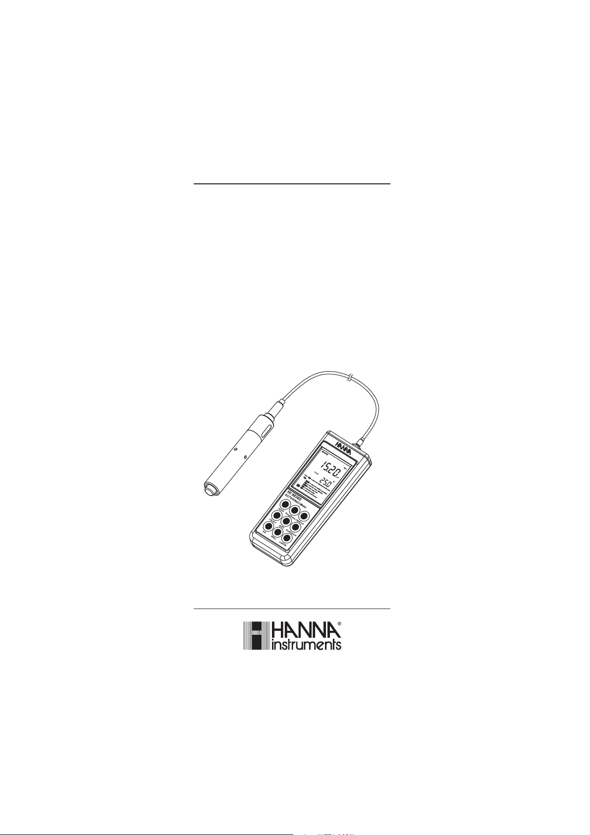
Instruction Manual
HI 9835 HI 98360
Auto Ranging
EC/TDS/NaCl/
Temperature Meters
www.hannainst.com
1
Page 2

Dear Customer,
Thank you for choosing a Hanna Instruments product.
Please read this instruction manual carefully before using the instruments.
This manual will provide you with the necessary information for correct
use of the instruments, as well as a precise idea of their versatility.
If you need additional technical information, do not hesitate to e-mail us
at tech@hannainst.com.
WARRANTYWARRANTY
WARRANTY
WARRANTYWARRANTY
HI 9835 and HI 98360 are guaranteed for two years against defects in
workmanship and materials when used for their intended purpose and
maintained according to instructions. Electrodes and probes are
guaranteed for six months. This warranty is limited to repair or replacement
free of charge.
Damage due to accidents, misuse, tampering or lack of prescribed
maintenance is not covered.
If service is required, contact the dealer from whom you purchased the
instrument. If under warranty, report the model number, date of purchase,
serial number and the nature of the problem. If the repair is not covered
by the warranty, you will be notified of the charges incurred. If the
instrument is to be returned to Hanna Instruments, first obtain a
Returned Goods Authorization number from the Technical Service department
and then send it with shipping costs prepaid. When shipping any
instrument, make sure it is properly packed for complete protection.
TABLE OF CONTENTSTABLE OF CONTENTS
TABLE OF CONTENTS
TABLE OF CONTENTSTABLE OF CONTENTS
WARRANTY ........................................................................................................... 2
PRELIMINARY EXAMINATION ................................................................................. 3
GENERAL DESCRIPTION ......................................................................................... 3
FUNCTIONAL DESCRIPTION .................................................................................... 4
SPECIFICATIONS ................................................................................................... 6
OPERATIONAL GUIDE ............................................................................................. 8
AUTO-RANGING ..................................................................................................... 9
AutoEnd ............................................................................................................. 10
TEMPERATURE COMPENSATION .......................................................................... 10
EC/TDS CALIBRATION ........................................................................................... 12
CONDUCTIVITY VERSUS TEMPERATURE CHART ...................................................... 14
NaCl CALIBRATION .............................................................................................. 15
GOOD LABORATORY PRACTICE (GLP) ..................................................................... 16
SETUP ................................................................................................................ 18
LOGGING (HI 98360 only) .................................................................................... 20
TEMPERATURE CALIBRATION (for technical personnel only) .................................. 21
PC INTERFACE (HI 98360 only) ........................................................................... 23
BATTERIES REPLACEMENT .................................................................................... 28
LCD MESSAGE GUIDE ........................................................................................... 30
PROBE MAINTENANCE ........................................................................................ 31
TROUBLESHOOTING GUIDE .................................................................................. 32
ACCESSORIES ..................................................................................................... 33
2
Page 3

PRELIMINARY EXAMINATIONPRELIMINARY EXAMINATION
PRELIMINARY EXAMINATION
PRELIMINARY EXAMINATIONPRELIMINARY EXAMINATION
Remove the instrument from the packing material and examine it carefully
to make sure that no damage has occurred during shipping. If there is any
damage, notify your Dealer or the nearest Hanna Customer Service Center.
Each instrument is supplied with:
• HI 76309 Conductivity probe with 1 m cable (HI 9835)
• HI 76309/1.5 Conductivity probe with 1.5 m cable (HI 98360)
• 3 x 1.5V AAA Batteries
• Instruction Manual
• Rugged Carrying Case
Note: Save all packing material until you are sure that the instrument
functions correctly. All defective items must be returned in the
original packing with the supplied accessories.
GENERAL DESCRIPTIONGENERAL DESCRIPTION
GENERAL DESCRIPTION
GENERAL DESCRIPTIONGENERAL DESCRIPTION
HI 9835 and HI 98360 are state-of-the-art, handheld conductivity
meters, designed to provide laboratory results and accuracy under harsh
industrial conditions.
These instruments are provided with a series of new diagnostic features
and messages on the LCD which add an entirely new dimension to the
measurement of EC, TDS and NaCl, by allowing the user to dramatically
improve the reliability of the measurement.
The autoranging feature of the EC and TDS ranges automatically sets the
meter to the scale with the highest possible resolution.
The Auto Endpoint feature automatically freezes the display when a
stable reading is reached.
The measurements are automatically (ATC) or manually (MTC)
compensated for temperature. The temperature coefficient value is
user selectable. It is possible to disable the temperature compensation
and measure the absolute (uncompensated) conductivity.
The HI 98360 also has a logging feature (up to 500 records) and
allows data transfer to computer through the USB port.
The Battery Error Preventing System (BEPS) detects when the batteries
become too weak to ensure reliable measurements.
The backlight feature is automatically disabled when batteries are getting
low and a clear indication is displayed to warn the user of this condition.
However, the meter continues to measure correctly even when the low
battery indication is displayed. The meter automatically switches itself off
when the batteries are too weak to support proper function.
In addition, the meters allow the user to enter an ID code to uniquely
identify the instrument.
3
Page 4
FUNCTIONAL DESCRIPTIONFUNCTIONAL DESCRIPTION
8
7
HI 98360
9
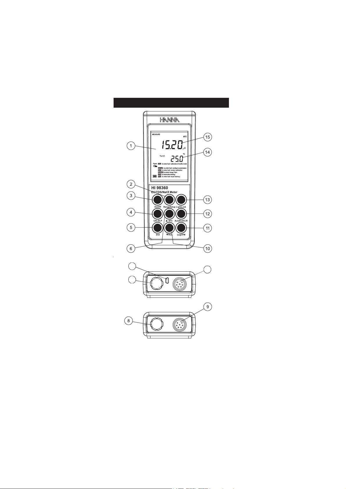
FUNCTIONAL DESCRIPTION
FUNCTIONAL DESCRIPTIONFUNCTIONAL DESCRIPTION
HI 9835
1) Liquid Crystal Display (LCD).
2) Range key, to select EC/TDS/NaCl range.
Setup key, to enter/exit SETUP mode.
3) On/Off key, to turn the instrument ON and OFF.
4) CAL key, to enter/exit calibration mode.
GLP key, to display Good Laboratory Practice information.
5) 2nd key, to select second key function.
4
Page 5

6) key, to manually increase temperature or other parameters.
ATC key, to select temperature compensation mode.
7) USB connector (HI 98360 only).
8) Battery compartment cap.
9) DIN connector for EC probe.
10) key, to manually decrease temperature or other parameters.
RCL key, to enter/exit view logged data mode (HI 98360 only).
11) Log key, to store measured data (HI 98360 only).
CFM key, to confirm different values.
12) AutoEnd key, to freeze first stable reading on the LCD.
CLR key, to delete logged data (HI 98360 only).
13) Light key, to toggle display backlighting.
Lock to freeze/unfreeze the current displayed range.
14) Secondary LCD.
15) Primary LCD.
5
Page 6
RA EGN
99.92ot00.0 µ mc/S
9.992ot0.03 µ mc/S
003
. 9992ot . µ mc/S
mc/Sm99.92ot00.3
mc/Sm0.002ot0.03
.0 mc/Sm0.005otpu
detasnepmocnu
)*(
ytivitcudnoc
mpp99.41ot00.0
mpp9.941ot0.51
051
. 9941ot . mpp
l/g99.41ot05.1
.p
l/g0.001ot0.51 .p
.0 l/g0.004otpu .p
detasnepmocnu
)*(
)rotcaf08.0htiw(SDT
lCaN%0.004ot0.0
Cº0.021ot0.02–
NOITULOSER
10.0 µ mc/S
0 1.0 µ mc/S
0.0 1 µ mc/S
mc/Sm10.0
0 mc/Sm1.0
mpp10.0
0 mpp1.0
0.0 mpp1
l/g10.0
p
0 l/g1.0 p
lCaN%1.0
Cº1.0
YCARUCCA
Fº86/Cº02@
50.0±gnidaerfo%1± Sµ mc/
retaergrevehcihw,tigid1ro
± rompp30.0±gnidaerfo%1
retaergrevehcihw,tigid1
± lCaNgnidaerfo%1
± )rorreeborpgnidulcxe(Cº2.0
noitarbilaCCE
:elbaliavasreffub6htiwtniop1
3141,0.48 µ mc/S
mc/Sm8.111,0.08,88.21,00.5
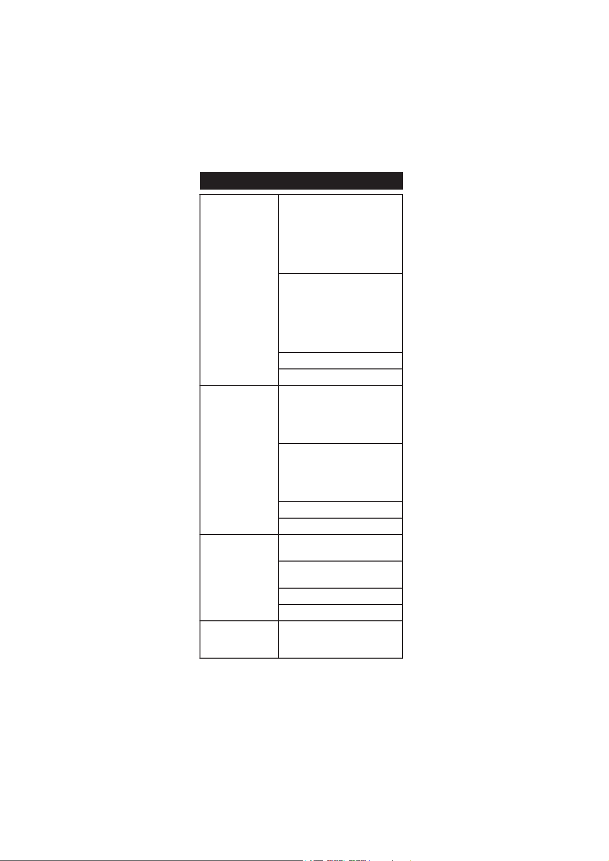
SPECIFICATIONSSPECIFICATIONS
SPECIFICATIONS
SPECIFICATIONSSPECIFICATIONS
(*)
Uncompensated conductivity (or TDS) is the conductivity (or TDS) value without
temperature compensation.
6
Page 7
noitarbilaClCaN
htiwtniop1 7307IH reffub
)lanoitpo(
erutarepmeT
noitarbilaC
C°05dna0ta,tniop2
)F°221dna23(
erutarepmeT
noitasnepmoC
morfcitamotuArolaunaM
)F°0.842ot0.4-(Cº0.021ot0.02–
etulosbaerusaemotdelbasidebnac(
)ytivitcudnoc
tneiciffeoCerutarepmeT
Cº/%00.6ot00.0
;)ylnoSDTdnaCErof(
Cº/%09.1sieulavtluafed
erutarepmeTecnerefeR Cº52roCº02
rotcaFSDT
08.0ot04.0
)05.0sieulavtluafed(
eborP
90367IH rofdedulcni(eborpCE
5389IH )
5.1/90367IH rofdedulcni(eborpCE
06389IH )
goL
dnamedno
(sdrocer005 06389IH )ylno
ffo-otuA
setunim06,02,01,5retfA
)delbasidebnac(
noitacinummoCCP (BSUdetalosiotpO 06389IH )ylno
efiL&epyTyrettaB
seirettarbAAA5.1x3
esusuoumitnocfosruoh002.xorppa
htiwsruoh05(thgilkcabtuohtiw
)thgilkcab
snoisnemiD )”4.1x8.2x3.7(mm63x27x581
thgieW )zo6.01(g003
tnemnorivnE
)Fº221–23(Cº05–0
%59HR.xam
ytnarraW sraey2
7
Page 8
OPERATIONAL GUIDEOPERATIONAL GUIDE
OPERATIONAL GUIDE
OPERATIONAL GUIDEOPERATIONAL GUIDE
INITIAL PREPARATION
The instrument is supplied complete with batteries. In order to place the
batteries inside the instrument follow the instructions from page 28.
To prepare the instrument for use, connect the EC probe to the input
socket on the top of the instrument.
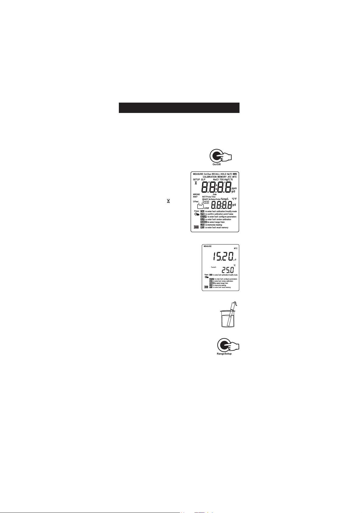
Turn the instrument ON by pressing On/Off.
At start-up the display will show all
the used segments for a few seconds
(or while the button is held), followed
by the percentage indication of the
remaining battery life. During
instrument startup the “ ” and
“WAIT” tags will blink.
The meter is now ready to operate.
Submerse the probe into the solution to be tested. The
sleeve holes must be completely submersed. Tap the
probe repeatedly to remove any air bubbles that
may be trapped inside the sleeve.
If needed, press the Range key repeatedly until the
desired range (EC, TDS, NaCl) is selected on the LCD.
Allow for the reading to stabilize. The upper LCD
displays the measure in the selected range while the
temperature is displayed on the lower LCD.
The auto-off feature turns the instrument off after a set period (default
20 minutes) with no button pressed to save battery life. To set another
period or to disable this feature, see SETUP menu on page 18.
The auto-off backlight feature turns the backlight off after a set period
(default 1 min) with no buttons pressed. To set another period or to
disable this feature, see SETUP menu on page 18.
8
Page 9
Notes: • If the reading is out of range, the full scale value will be
displayed blinking.
• If the reading is not stable, the instability indicator “ ” will
be on.
• Make sure the meter is calibrated before taking measurements.
• If measurements are taken successively in different samples, it
is recommended to rinse the probe thoroughly with deionized
water before immersion in the samples. If possible rinse with
sample also.
• To maximize battery life, the meter is automatically switched
off after a set period of non-use. To reactivate the instrument
press the On/Off key. This feature can be disabled (see
SETUP section for details).
• TDS reading is obtained multiplying the EC reading by the
TDS factor, which has a default value of 0.50. It is possible to
change the TDS factor in the 0.40 to 0.80 (see SETUP
section). Always set the reference temperature to 25°C when
measuring TDS.
• When the use of an alternate function is requested, press the
2nd key.
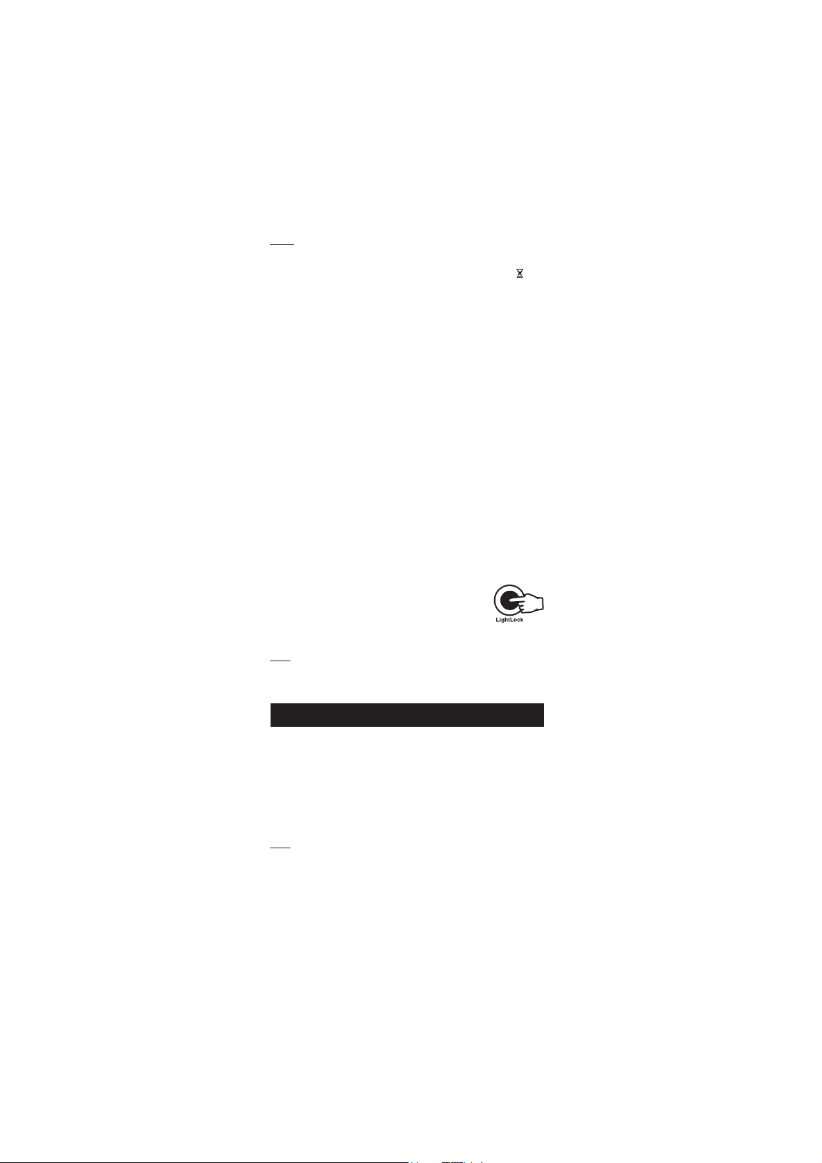
BACKLIGHT FEATURE
The instrument is provided with a Backlight feature to
enhance display readability in low light conditions. It
can be easily toggled on and off through the keypad by
pressing Light.
Note: The backlight automatically shuts off after a set time period to
save battery life (see SETUP for details, page 18).
If battery percentage is less than 20% the backlight can not be ON.
AUTO-RANGINGAUTO-RANGING
AUTO-RANGING
AUTO-RANGINGAUTO-RANGING
The EC and TDS scales are auto-ranging. The meter automatically sets
the scale with the highest possible resolution.
By pressing 2nd then Lock, the auto-ranging feature is disabled and
the current range is frozen on the LCD. The “MEASURE” tag is displayed
blinking.
To restore the auto-ranging option press 2nd then Lock again.
Note: Auto-ranging is automatically restored if the Range or 2nd then
Lock keys are pressed, if the setup or calibration modes are
entered and if the meter is turned off and back on again.
• If 2nd then Lock was pressed to freeze the LCD range and the
reading goes out of range, the full-scale value of the frozen range will
be displayed blinking.
9
Page 10

AA
utoEndutoEnd
A
utoEnd
AA
utoEndutoEnd
To freeze the first stable reading on the LCD
press AutoEnd while the instrument is in
measurement mode.
The ”HOLD” tag will be displayed blinking on
the LCD until the reading is stabilized.
When the reading is stable, the “HOLD” tag
stops blinking and the reading is frozen on
the LCD.
Press AutoEnd again to return to normal measurement mode.
Note: • Pressing Range the instrument will skip to the displayed
range, without leaving AutoEnd mode. The Log key also
holds AutoEnd mode.
• Pressing 2nd then Setup, GLP or RCL, the instrument
leaves AutoEnd mode and performs the selected function.
TEMPERATURE COMPENSATIONTEMPERATURE COMPENSATION
TEMPERATURE COMPENSATION
TEMPERATURE COMPENSATIONTEMPERATURE COMPENSATION
The EC reading is affected by temperature and changes in ion concentration.
To measure only one variable, conductivity measurements are normally
compensated to a fixed temperature. This reference temperature is
configured in SETUP parameter rEF. See page 18.
Three options of temperature compensation are available:
Automatic (Atc): The probe has a built-in temperature sensor; the
value of the temperature is used to automatically compensate the EC/TDS
measurement to a reference temperature. This is the default option.
Manual (Mtc): The temperature value, shown on the lower LCD, can be
manually set by the user with the up and down arrow keys to the
solution temperature. The “ºC” or “ºF” symbol blinks when this option is
active. The instrument compensates the conductivity measured at this
temperature to the reference temperature.
No Compensation (NoTC): The temperature reading shown on the
lower LCD is not taken into account. The reading displayed on the upper
LCD is the absolute EC or TDS value without temperature compensation
applied. The measurement changes due to temperature and ion
concentration. The second “ºC” or “ºF” symbol blinks when this option is
active.
10
Page 11

To select the desired option press the 2nd then ATC key. The option tag
will blink for a few seconds then remain active on the LCD.
If temperature compensation is active, measurements are compensated
using a default temperature coefficient of 1.90 %/°C to the 25°C
reference temperature. This is a natural water tc value.
It is possible to view or select a different temperature coefficient (TC) in the
0.00 to 6.00 %/°C range by entering the setup mode and selecting the
“tc” item (see SETUP section for details).
Notes: • The default compensation mode is Atc.
• If no temperature probe is detected, Atc mode can not be
selected and the instrument displays “----” on the secondary
LCD.
• If the temperature reading is out of the -20.0 – 120.0 ºC
range and Atc option is selected, the “ºC” tag will blink and
the closest interval limit will be displayed.
• By pressing the ARROW keys the displayed temperature
value is changed. This value is used to compensate the
EC/TDS reading.
Temperature compensation is performed by means of the following formula:
Compensated conductivity =
where T is the measured temperature and T
Measured conductivity
1+TC25(T-T
)
ref
is the reference
ref
temperature (20 or 25°C).
Note that if a solution has a temperature coefficient TC with T
=25°C,
ref
when changing the reference temperature to 20°C, the temperature
coefficient must be manually adjusted by the user according to the
following formula:
TC20=
TC
25
1-TC25/20
For example, TC20=2.10%/°C when TC25=1.90%/°C.
Always set reference temperature to 25°C when measuring TDS.
TDS MEASUREMENTS
Press the Range key while in EC range. The instrument will switch to TDS
measuring range. The TDS reading will be displayed on the primary LCD
and the temperature reading on the secondary LCD.
• If the reading is out of range, the full-scale value (100.0 for MTC/ATC
mode or 400.0 for uncompensated TDS) will be displayed blinking.
11
Page 12

NaCl MEASUREMENTS
Percent sodium chloride on these meters refers to percentage of seawater
salinity. 100% is equal to seawater. The scale goes from 0 - 400%.
Press the Range key while in EC range until NaCl is displayed on the LCD.
The instrument will display the NaCl reading on the primary LCD and the
temperature reading on the secondary LCD line.
• If the reading is out of range, the full-scale value (400.0%) will be
displayed blinking.
EC/TDS CALIBRATIONEC/TDS CALIBRATION
EC/TDS CALIBRATION
EC/TDS CALIBRATIONEC/TDS CALIBRATION
EC calibration on these meters is a single point procedure. Selectable
calibration points are: 0.0 for offset and 84.0 µS/cm, 1413 µS/cm,
5.00 mS/cm, 12.88 mS/cm, 80.0 mS/cm,
111.8 mS/cm for slope.
To enter EC calibration select the EC range and
press the CAL key.
Note: TDS reading is automatically derived from the EC reading
and no specific calibration for TDS is needed. Pressing
CAL while TDS range is selected has no effect.
Rinse the probe with some of the calibration solution or deionized water.
Submerse the probe into the solution. The sleeve holes must be
completely submersed. Tap the probe repeatedly to remove any air
bubbles that may be trapped inside the sleeve.
For zero calibration, suspend the dry probe in air.
This calibration is performed in order to correct the reading arround
0.0 µS/cm.
Press CAL and the “CALIBRATION” tag is
displayed and “NOT READY”, “~” and “ ”
will blink. The primary LCD will display the EC
reading. The secondary LCD will display the
standard value.
Select the desired calibration value with the
ARROW keys, if necessary.
12
Page 13

When the reading is stable, “READY” tag
is displayed and “CFM” along with “~”
tag starts blinking on the LCD, asking for
confirmation.
Press CFM (or 2nd then CFM) to confirm
calibration.
The instrument stores the calibration value
and returns to measurement mode.
Notes: • If the uncalibrated reading is too far from the expected
value, the “WRONG” tag will blink. Calibration can not be
confirmed. In this case check if the correct standard has been
used or clean the probe by following the Probe Maintenance
(see page 31).
• If the meter is in MTC or ATC mode
and the standard temperature is
out of the 0.0 - 60.0 ºC interval,
“WRONG” “ºC” tags and the
temperature will be displayed
blinking.
• For best results choose an EC standard value close to the
sample to be measured.
• In order to minimize any EMC interference, use plastic or
glass beakers.
• It is possible to set the cell constant value directly in according
with the specifications of the electrode indicated by the
manufactures, without following the calibration procedure.
To set the cell constant, enter SETUP mode and select “CELL”
(see SETUP for details, page 18).
13
Page 14

CONDUCTIVITY VERSUSCONDUCTIVITY VERSUS
Cº Fº
0307IH
0308IH
(
µ )mc/S
1307IH
1308IH
(
µ )mc/S
3307IH
3308IH
(
µ )mc/S
4307IH
4308IH
(
µ )mc/S
5307IH
5308IH
(
µ )mc/S
9307IH
9308IH
(
µ )mc/S
0 23 0517 677 46 00384 00456 0672
5 14 0228 698 56 00535 00147 0813
01 05 0339 0201 76 00695 00238 5163
51 95 08401 7411 86 00456 00529 3604
61 8.06 02701 3711 07 00276 00449 5514
71 6.26 05901 9911 17 00586 00369 5424
81 4.46 09111 5221 37 00896 00289 7334
91 2.66 03411 1521 47 00317 002001 9244
02 86 07611 8721 67 00427 001201 3254
12 8.96 01911 5031 87 00047 000401 7164
22 6.17 05121 2331 97 00257 009501 1174
32 4.37 09321 9531 18 00567 009701 5084
42 2.57 04621 6831 28 00387 008901 2094
52 77 08821 3141 48 00008 008111 0005
62 8.87 03131 0441 68 00318 008311 6905
72 6.08 07331 7641 78 00038 007511 0915
82 4.28 02631 4941 98 00948 007711 6825
92 2.48 07831 1251 09 00368 007911 3835
03 68 02141 8451 29 00288 008121 9745
13 8.78 07341 5751 49 00009 009321 5755
CONDUCTIVITY VERSUS
CONDUCTIVITY VERSUSCONDUCTIVITY VERSUS
TEMPERATURE CHARTTEMPERATURE CHART
TEMPERATURE CHART
TEMPERATURE CHARTTEMPERATURE CHART
The conductivity of an aqueous solution is a measure of its ability to carry
an electrical current by means of ionic motion.
The conductivity invariably increases with increasing temperature.
It is affected by the type and number of ions in the solutions and by
the viscosity of the solution itself. Both parameters are temperature
dependent. The dependency of conductivity on temperature is
expressed as a relative change per Celsius degrees at a particular
temperature, commonly as %/ºC.
The following table lists the temperature dependence of HANNA EC
calibration standards.
14
Page 15

NaCl CALIBRATIONNaCl CALIBRATION
NaCl CALIBRATION
NaCl CALIBRATIONNaCl CALIBRATION
NaCl calibration is a one-point procedure at 100.0% NaCl. Use the
HI 7037L calibration solution (sea water solution) as a 100% NaCl
standard solution.
Rinse the probe with some of the calibration solution or
deionized water. Submerse the probe into HI 7037L
solution. The sleeve holes must be completely submersed.
Tap the probe repeatedly to remove any air bubbles that
may be trapped inside the sleeve.
To enter NaCl calibration select the NaCl range and press
CAL.
The “CALIBRATION” tag is displayed, “NOT
READY”, “~” and “ ” start blinking. The
primary LCD will display the NaCl reading in
percentage. The secondary LCD will display
“100”.
When the reading is stable, the “READY”
tag will be displayed and the “CFM”
tag starts blinking on the LCD, asking
for confirmation.
Press CFM to confirm calibration.
The instrument stores the calibration value
and returns to measurement mode.
Notes: • If the reading is too far from the
expected value, “WRONG” and
“ ” tags will blink. Calibration
cannot be confirmed.
• If the temperature of the standard
is out of the 0.0 – 60.0 ºC
temperature range, the
“WRONG”, “ ” and “ºC” tags and the temperature
will be displayed blinking.
• If the meter range is changed to EC, and a new EC calibration
is performed, the NaCl calibration is automatically cleared.
Thus, a new NaCl calibration is required.
15
Page 16

GOOD LABORATORY PRACTICE (GLP)GOOD LABORATORY PRACTICE (GLP)
GOOD LABORATORY PRACTICE (GLP)
GOOD LABORATORY PRACTICE (GLP)GOOD LABORATORY PRACTICE (GLP)
GLP is a set of functions that allows storage and retrieval of data
regarding the calibration and status of the probe and meter.
All data regarding EC or NaCl calibration is stored for the user to review
when necessary.
LAST EC CALIBRATION DATA
The last EC calibration data is stored automatically after a successful
calibration. To view the EC calibration data, press 2nd then GLP when
the instrument is in EC measurement mode.
The instrument will display the date (mm.dd)
and the time (hh:mm) of the last calibration.
Press the ARROW keys to view the next calibration parameter.
Pressing the key:
• The EC calibration offset factor.
• The calibration cell constant.
• The calibration standard.
16
Page 17

• The temperature coeficient.
• The instrument ID.
LAST NaCl CALIBRATION DATA
Last NaCl calibration data is stored automatically after a successful
calibration.
To view the NaCl calibration data, press GLP when the instrument is in
NaCl measurement mode. The instrument will display:
• The date and time.
Press the ARROW key to view the next logged calibration parameters
(pressing the key).
• The cell constant (as for EC range).
• The salinity coefficient.
• The instrument ID (as for EC range).
Notes: • If NoTC is selected as temperature compensation mode during
calibration, the temperature coefficient is not displayed in
GLP.
• Press GLP at any moment and the instrument will return to
measurement mode.
• If calibration has not been performed in NaCl range, the
instrument displays “no CAL” message blinking.
17
Page 18

SETUPSETUP
SETUP
SETUPSETUP
Setup mode allows viewing and modifying the following parameters:
• Cell constant (CELL)
• TDS factor (FAct)
• Temperature coefficient (tc)
• Reference temperature (rEF)
• Current Time (hour & minute)
• Current Date (month, day & year)
• Beep Status (bEEP)
• Instrument ID (InSId)
• Auto-off backlight timer (LIGH)
• Auto power off timer (AOFF)
• Temperature Unit
To enter SETUP mode, press 2nd then Setup while the instrument is in
measurement mode.
Select the desired setup parameter using the
ARROW
keys.
Press CAL if you want to change the item
value. “CFM” tag and the selected item (e.g.
hour, in setting up the correct time) will start
blinking.
Press the ARROW
displayed value.
If there is another item to be set (e.g.
minutes), press Range. The other item will
start blinking.
Press the ARROW
displayed value.
Press CFM (or 2nd then CFM) to confirm or
CAL to escape without saving.
Press the ARROW
Press Setup to exit SETUP menu at any time.
The following table (see page 19) lists the SETUP parameters, their valid
values range and the factory settings (default). Use to move through
parameters in this order.
keys to change the
keys to change the
keys to select the next/previous parameter.
18
Page 19

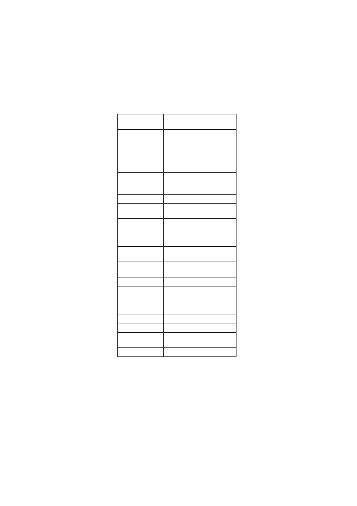
SRETEMARAPPUTES
noitaiverbbA seodtitahW
dilaV
seulaV
tluafeD
LLEC .eborpCEroftnatsnoclleC
ot005.0
mc/007.1
mc/000.1
SDTtcAF
ytivitcudnoctrevnocotdesurotcaF
eulavdilosdevlossidlatotaot
;5=tcAFnehW.mppnideyalpsid
asisihT.mpp05=mc/Su001
lartuenarofnoitamixorppadoog
.noitulostlas
ot04.0
08.0
05.0
ct
noitasnepmocerutarepmetasict
citamotuAnidesusitahtrotcaf
erutarepmetlaunaMdna
desusirotcafsihT.noitasnepmoc
erutarepmetehthtiw
eht"tcerroc"ottnemerusaem
ecnereferaottnemerusaem
.11egapeeS.erutarepmet
ot00.0
C°/%00.6
C°/%9.1
FEr
desueulaverutarepmetehtsiFEr
ecnerefererutarepmetehT.evoba
.cificepslanoigersi
C°52ot02 C°52
emiT
ecnereferotdesusieulavsihT
agnisugniggoldnasnoitarbilac
)mm:hh(.kcolcruoh42
ot00:00
95:32
00:0
etaD
ecnereferotdesusieulavsihT
.gniggoldnasnoitarbilac
)yyyy.dd.mm(
0002.10.10
ot
9902.13.21
9002.10.10
PEEb
srorrelangisotdesuenotpeeB
.egnahcgnimrifnocdna
ffO/nO FFO
dISnI
sihteviG:DItnemurtsnI
nehW.#teercsidatnemurtsni
tnemurtsnisihtsgolgnidaolnwod
.deifitnedieblliw
ot0000
9999
0
HGIL
sithgilkcabfI.remitthgilkcaB
ebottistimrep,yalpsidnodenrut
evasotffodenrutyllacitamotua
.rewopyrettab
ro5,1,ffO
setunim01
etunim1
FFOA
nrutottinustimreP:remitffootuA
yrettabevasotemitteserpretfaffo
.rewop
,01,5,ffO
06ro02
setunim
setunim02
.deyalpsidtinuerutarepmeT F°roC° C°
19
Page 20

LOGGING (HI 98360LOGGING (HI 98360
LOGGING (HI 98360
LOGGING (HI 98360LOGGING (HI 98360
This feature allows the user to log EC, TDS or NaCl measurements,
together with corresponding temperature automatically. All logged data
can be transferred to a PC through the USB port.
The maximum logging space is 500 record locations.
LOGGING THE CURRENT DATA
To store the current reading into
memory, press Log while in
measurement mode.
The instrument will display the current date
(mm.dd) on the primary LCD, the record number
on the secondary LCD and then the number of
available tags remaining.
If there are less than 6 memory locations
remaining, the “Lo” message will blink for a
few seconds to alert the user, and then the
available log number is displayed on the LCD.
If the LOG space is full, “FULL LOG” message
will be displayed on the LCD for a few seconds
and then ”FrEE 0” message.
The instrument returns to normal measurement
mode.
VIEW LOGGED DATA
Press 2nd then RCL to retrieve the information stored while in measurement
mode for the specific range. “RECALL MEMORY” will be displayed on LCD.
If no records were logged, the instrument will
display “no rEC” message blinking.
Otherwise, the instrument will display the
logged data, in according with the selected
range:
• If RCL mode was entered while the instrument
was in EC range: the last EC memorized
reading appears on the primary LCD and
the record number on the secondary LCD.
• If RCL mode was entered while the instrument
was in TDS range: the last TDS memorized
reading appears on the primary LCD and
the record number on the secondary LCD.
only only
only
only only
))
)
))
20
Page 21

• If RCL mode was entered while the instrument was in NaCl range:
the last NaCl memorized reading appears on the primary LCD and
the record number on the secondary LCD.
Press 2nd then Setup while in RECALL mode,
when the record number is not displayed and
the instrument will toggle between the record
number on the secondary LCD and the current
displayed information. Use the ARROW keys
to select another record.
Press Range and the instrument will display the next logged parameter
as shown in the table below:
Parameter Primary LCD Secondary LCD
EC EC reading Temperature
DATE/TIME Month & day Hour & minutes
Cell/Off Cell value Offset value
Press 2nd then CLR or simply CLR to delete records.
The “dEL” message is displayed on the primary LCD, the record number on
the secondary LCD and “CFM” tags will blink.
• Press the ARROW keys to change the record number.
• Press CAL or Range or CLR to escape from DEL screen and enter view
record items mode.
Note: Pressing 2nd then Setup the instrument toggles between record
number and all records.
• Press 2nd then CFM or CFM to confirm delete. The “nuLL” message
will be displayed on the primary LCD for the selected record. While
“nuLL” message is displayed the 2nd, CAL, Range and CLR keys
are inactive. Press the ARROW keys to select an undeleted record.
• If “dEL ALL” option was selected, all logged data are deleted and
the instrument returns to measurement mode.
Press 2nd then RCL at any time to return to measurement mode.
The “ ” and “WAIT” tags blinks during memory reorganization.
TEMPERATURE CALIBRATIONTEMPERATURE CALIBRATION
TEMPERATURE CALIBRATION
TEMPERATURE CALIBRATIONTEMPERATURE CALIBRATION
(for technical personnel only)
All the instruments are factory calibrated for temperature.
Hanna’s temperature probes are interchangeable and no temperature
calibration is needed when they are replaced.
If the temperature measurements are inaccurate, temperature recalibration
should be performed.
21
Page 22

For an accurate recalibration, contact your dealer or the nearest Hanna
Customer Service Center, or follow the instructions below.
• Prepare a vessel containing ice and water and another one containing
hot water (at approximately 50 ºC or 122 ºF). Place insulation
material around the vessels to minimize temperature changes.
• Use a calibrated thermometer with a resolution of 0.1 ºC as a
reference thermometer. Connect the EC probe to the appropriate
socket.
• With the instrument off, press and hold down the Range & keys,
then power on the instrument. The “CALIBRATION” tag will
appear and the secondary LCD will show “0.0 ºC”. The primary LCD
will display the measured temperature or the ”----” message, if the
measured temperature is out of range.
• Submerse the temperature probe into the vessel with ice and water
as close as possible to the reference thermometer. Allow a few seconds
for the probe to stabilize.
• Use the ARROW keys to set the reading on the secondary LCD to that
of ice and water, measured by the reference thermometer. When the
reading is stable and close to the selected calibration point, “CFM”
tag will blink.
• Press CFM to confirm. The secondary LCD will
display “50.0 ºC”.
• Submerse the temperature probe into the second vessel as close as
possible to the reference thermometer. Allow a few seconds for the
probe to stabilize.
• Use the ARROW keys to set the reading on the secondary LCD to that
of the hot water.
• When the reading is stable and close to the selected calibration
point, “CFM” tag will blink.
• Press CFM to confirm. The instrument returns
to measurement mode.
Note: If the reading is not close to the selected calibration point,
“WRONG” tag will blink. Change the temperature probe and
restart calibration.
22
Page 23

PC INTERFACE (HI 98360 PC INTERFACE (HI 98360
PC INTERFACE (HI 98360
PC INTERFACE (HI 98360 PC INTERFACE (HI 98360
Data transmission from the instrument to the PC can be done with the
HI 92000 Windows® compatible software (optional). HI 92000 also
offers graphing and an on-line help feature.
Data can be exported to the most popular spreadsheet programs for
further analysis.
To connect your instrument to a PC, use a standard USB cable. Make
sure that your instrument is switched off and plug one connector to the
instrument’s USB socket and the other to the USB port of your PC.
Note: If you are not using Hanna Instruments HI 92000 software,
please see the following instructions.
In order to avoid data errors the serial communication interface is not
available if the battery percentage is less than 30%. The instrument will
answer with an “Err9” message.
SENDING COMMANDS FROM PC
It is also possible to remotely control the instrument with any terminal
program. Use a standard USB cable to connect the instrument to a PC,
start the terminal program and set the communication options as follows:
8, N, 1, no flow control, baud rate 9600.
COMMAND TYPES
To send a command to the instrument follow the next scheme:
<command prefix> <command> <CR>
where: <command prefix> is 16 ASCII character.
<command> is the command code.
Note: Either small or capital letters can be used.
SIMPLE COMMANDS
RNG Is equivalent to pressing RANGE
CAL Is equivalent to pressing CAL
CFM Is equivalent to pressing CFM
UPC Is equivalent to pressing the UP arrow key
DWC Is equivalent to pressing the DOWN arrow key
LOG Is equivalent to pressing LOG
RCL Is equivalent to pressing RCL
SET Is equivalent to pressing SETUP
CLR Is equivalent to pressing CLR
OFF Is equivalent to pressing OFF
AED Is equivalent to pressing AutoEnd
onlyonly
only
onlyonly
))
)
))
23
Page 24

CHR xx Change the instrument range according with the parameter
value (xx):
• xx=06 EC range
• xx=07 TDS range
• xx=08 NaCl range
The instrument will answer for these commands with:
<STX> <answer> <ETX>
where: <STX> is 02 ASCII code character (start of text)
<ETX> is 03 ASCII code character (end of text)
<answer>:
<ACK> is 06 ASCII code character (recognized command)
<NAK> is 21 ASCII code character (unrecognized command)
<CAN> is 24 ASCII code character (corrupted command)
COMMANDS REQUIRING AN ANSWER
The instrument will answer for these commands with:
<STX> <answer> <checksum> <ETX>
where the checksum is the bytes sum of the answer string sent as 2 ASCII
characters.
All the answer messages are with ASCII characters.
RAS Causes the instrument to send a complete set of readings in
according with the current range:
• EC and temperature reading on EC range.
• TDS, EC and temperature reading on TDS range.
• NaCl, EC and temperature reading on NaCl range.
The answer string contains:
• Meter mode (2 chars):
• 06 - EC range
• 07 - TDS range
• 08 - NaCl range
• Meter status (2 chars of status byte): represents a 8
bit hexadecimal encoding.
• 0x40 - TDS unit (0-ppm, 0-g/L)
• 0x20 - EC unit (0-µS, 1-mS)
• 0x10 - temperature probe is connected
• 0x01 - new GLP data available
• 0x02 - new SETUP parameter
• 0x08 - AUTOHOLD is stable
24
Page 25

• Reading status (1 char): R - in range, O - over
range, U - under range.
• The reading (corresponding to the selected range) 7 ASCII chars, including sign and decimal point.
• Temperature reading - 8 ASCII chars, with sign and
two decimal points, always in ºC.
MDR Requests the instrument model name and firmware code
(16 ASCII chars).
GLP Requests the calibration data record.
The answer string contains:
• GLP status (1 char): represents a 4 bit hexadecimal
encoding.
• 0x04 - EC calibration available
• 0x08 - NaCl calibration available
• EC calibration data (if available), which contains:
• the number of calibrated satandard (1 char)
• the offset factor, with sign and decimal point
(7 chars)
• the cell constant, with sign and decimal point
(7 chars)
• the calibration time, yymmddhhmmss (12 chars)
• standards information
• standard value, with sign and decimal point
(7 chars).
• standard unit (2 chars; 00-µS; 01-mS)
• Reference Temperature with and decimal point
(5 chars)
• Temperature Compensation mode (2 chars)
• 00 - no temperature compensation
• 01 - automatic temperature compensation
• 02 - manual temperature compensation
• TC coeficient with sign and decimal point (5 chars)
• Na Cl Calibration data
• the number of calibrated standards (1 char)
• salinity coeficient, with sign and decimal point
(7 chars)
• Cell constant, with sign and decimal point
(7 chars)
25
Page 26

• the calibration time (12 chars)
• standard unit (always 00 - 2 chars)
• Reference Temperature with and decimal point
(4 chars)
• Temperature Compensation mode (2 chars)
• 00 - no temperature compensation
• 01 - automatic temperature compensation
• 02 - manual temperature compensation
• TC coeficient with sign and decimal point (5 chars)
PAR Requests the setup parameters setting.
The answer string contains:
• Instrument ID (4 chars)
• SETUP information (2 chars): 8 bit hexadecimal
encoding.
• 0x01 - beep ON (else OFF)
• 0x04 - degrees Celsius (else degrees Fahrenheit)
• Auto-off/Light time (3 chars) (in minutes)
• Auto power off time (3 chars) (in minutes)
• Cell constant, with sign and decimal point (6 chars)
• TDS factor, with sign and decimal point (5 chars)
• TC coef, with sign and decimal point (5 chars)
• Reference Temperature, with sign and decimal point
(5 chars)
• Temperature Compensation mode (1 char)
NSLx Requests the number of logged samples (4 chars).
The command parameter (1 char):
• E - request for EC range
• N - request for NaCl range
• T - request for TDS range
LODExxx Requests the xxxth EC record logged data.
LODNxxx Requests the xxxth NaCl record logged data.
LODTxxx Requests the xxxth TDS record logged data.
LODEALL Requests all EC Log on demand.
LODNALL Requests all NaCl Log on demand.
LODTALL Requests all TDS Log on demand.
26
Page 27

The answer string for each record contains the number of records if ALL
data is requested - 3 chars
• The logged mode (2 chars):
• 06 - EC range
• 07 - TDS range
• 08 - NaCl range
• Reading status (1 char): R, O, U
• Calculated reading, with sign and decimal point
(7 chars)
• Temperature reading, with sign and two decimal
points (8 chars)
• EC reading status (1 char): R, O, U - for TDS,
NaCl range
• Unit of the reading - for TDS, NaCl range (1 char)
• The EC reading, with sign and decimal point - for
TDS, NaCl range (7 chars)
• The logged time, yymmddhhmmss (12 chars)
• The calibration offset, with sign and decimal point
(7 chars)
• The calibration slope, with sign and decimal point
(7 chars) (Kcell for EC and TDS range and the slope
for NaCl).
• Temperature probe presence (1 char)
• Temperature compensation coefficient (5 chars)
• Temperature reference value (5 chars)
• Temperature compensation mode (1 char)
Notes: • “Err8” is sent if the instrument is not in measurement mode.
• “Err6” is sent if the requested range is not available.
• “Err4” is sent if the requested set parameter is not available.
• “Err3” is sent if the Log on demand is empty.
• “Err9” is sent if the battery power is less than 30%.
• Invalid commands will be ignored.
27
Page 28

BATTERIES REPLACEMENTBATTERIES REPLACEMENT
BATTERIES REPLACEMENT
BATTERIES REPLACEMENTBATTERIES REPLACEMENT
If the batteries become weak, the display will
flash the battery symbol to advise the user
that approx. 1 hour of working time is left.
It is recommended to change the batteries as
soon as the battery indicator blinks (lower
frequency).
To replace the batteries, follow the next steps:
• Turn the instrument OFF.
• Open the battery compartment cap (located on the top of the
instrument).
• Remove old batteries.
• Insert three new 1.5V AAA batteries in the battery compartment,
following the instructions on the rear of the instrument.
• Reattach the battery compartment cap.
28
Page 29

The instrument is provided with the BEPS (Battery Error Prevention
System) feature, which automatically turns the instrument off when the
batteries level is too low to ensure reliable readings. At start up the
display will show “0 bAtt” message for a few seconds, then the
instrument automatically turns off.
29
Page 30

LCD MESSAGE GUIDELCD MESSAGE GUIDE
LCD MESSAGE GUIDE
LCD MESSAGE GUIDELCD MESSAGE GUIDE
TAGS & SYMBOLS
• Mode tags light up for indicating the corresponding active mode,
and blink for warning the user.
MEASURE on: Instrument in measurement mode.
SETUP on: SETUP menu mode has been entered.
CALIBRATION on: calibration mode has been entered.
GLP on: GLP mode has been entered.
RECALL MEMORY on: RECALL MEMORY mode has been entered.
• Reading in HOLD:
HOLD on: reading frozen in AutoEnd mode.
HOLD blinking: reading unstable in AutoEnd mode.
• Indication of temperature compensation mode:
MTC for manual, ATC for automatic compensation.
• blinking (while in calibration): reading unstable.
• Main active key messages light up for indicating the corresponding
active key.
CAL on: CAL key available.
CFM blinking: ask confirmation of calibration or set value.
SETUP on: SETUP key available.
GLP on: GLP key available.
RANGE on: RANGE key available.
LOG on: LOG key available.
RCL on: RLC key available.
30
Page 31

• Battery symbol blinking: low battery condition. The batteries
shoud be replaced soon.
PROBE MAINTENANCEPROBE MAINTENANCE
PROBE MAINTENANCE
PROBE MAINTENANCEPROBE MAINTENANCE
EC PROBE MAINTENANCE
Rinse the probe with clean water after measurements. If a more thorough
cleaning is required, remove the probe sleeve and clean the probe with
a cloth or a nonabrasive detergent. Make sure to reinsert the sleeve onto
the probe properly and in the right direction. After cleaning the probe,
recalibrate the instrument.
31
Page 32

SMOTPMYS MELBORP NOITULOS
puetautculfsgnidaeR
.)esion(nwoddna
toneveelseborpCE
ria;detresniylreporp
.eveelsedisniselbbub
evomeroteborpehtpaT
.selbbubria
tonseodretemehT
dradnatsehttpecca
.noitarbilacrofnoitulos
.eborpCEredrofotuO ecnanetniamehtwolloF
onllitsfI.erudecorp
ehtecalperstluser
.edortcele
,CEswohsyalpsidehT
gnidaerlCaNroSDT
.gniknilb
SDT,CEniegnarfotuO
.elacslCaNro
.retemehtetarbilaceR
sinoitulosehterusekaM
.egnardeificepsni
ehterusekaM KCOL yek
.desserptonsaw
tonseodretemehT
.erutarepmeterusaem
erutarepmetnekorB
.eborp
.eborpCEehtecalpeR
otsliafretemehT
ytluafsevigroetarbilac
.sgnidaer
.eborpnekorB .eborpehtecalpeR
otsliafretemehT
.lCaNetarbilac
tcerrocnI
lCaN
.noitarbilac niretemehtetarbilaceR
lCaN
.egnar
.1ottnatsnocllecteS
retemehtputratstA
sgatDCLllasyalpsid
.yltnenamrep
sisyekehtfoenO
.dekcolb
rodraobyekehtkcehC
.rodnevehttcatnoc
" xxrrE egassemrorre"
dnadeyalpsidsi
eht
retem
.ffosnrut
.rorrelanretnI ehtfI.retemehtnorewoP
ehttcatnoc,stsisreprorre
.rodnev
seodtnemurtsniehT
nehwpotsrotratston
gnisserp FFO/NO .
.rorrenoitazilaitinI nwoddlohdnasserP
FO/NO 51tuobarofF
sdnoces
erawdraharof
teser
,tsisreprorreehtfI.
tcatnoc
uoy
ynarorelaedr
.retneCecivreSannaH
"
laC euD " " dorP "
.putratstaegassem
yrotcaftontnemurtsnI
.detarbilac
lacinhceTannaHtcatnoC
yrotcafroftroppuS
.noitarbilac
TROUBLESHOOTING GUIDETROUBLESHOOTING GUIDE
TROUBLESHOOTING GUIDE
TROUBLESHOOTING GUIDETROUBLESHOOTING GUIDE
32
Page 33

ACCESSORIESACCESSORIES
ACCESSORIES
ACCESSORIESACCESSORIES
CONDUCTIVITY CALIBRATION SOLUTIONS
HI 70030P 12880 µS/cm solution, 20 mL sachet (25 pcs.)
HI 7030L 12880 µS/cm solution, 500 mL bottle
HI 7030M 12880 µS/cm solution, 230 mL bottle
HI 70031P 1413 µS/cm solution, 20 mL sachet (25 pcs.)
HI 7031L 1413 µS/cm solution, 500 mL bottle
HI 7031M 1413 µS/cm solution, 230 mL bottle
HI 70033P 84 µS/cm solution, 20 mL sachet (25 pcs.)
HI 7033L 84 µS/cm solution, 500 mL bottle
HI 7033M 84 µS/cm solution, 230 mL bottle
HI 7034L 80000 µS/cm solution, 500 mL bottle
HI 7034M 80000 µS/cm solution, 230 mL bottle
HI 7035L 111800 µS/cm solution, 500 mL bottle
HI 7035M 111800 µS/cm solution, 230 mL bottle
HI 70039P 5000 µS/cm solution, 20 mL sachet (25 pcs.)
HI 7039L 5000 µS/cm solution, 500 mL bottle
HI 7039M 5000 µS/cm solution, 230 mL bottle
HI 7037L 100% NaCl sea water standard solution, 500 mL bottle
PROBE CLEANING SOLUTIONS
HI 7061M General Cleaning Solution, 230 mL bottle
HI 7061L General Cleaning Solution, 500 bottle
33
Page 34

OTHER ACCESSORIES
HI 76309 PVC Conductivity/TDS probe with 4-rings (stainless
steel), temperature sensor and 1 m cable.
HI 76309/1.5 PVC Conductivity/TDS probe with 4-rings (stainless
steel), temperature sensor and 1.5 m cable.
HI 710005 12VDC voltage adapter (US plug)
HI 710006 12VDC voltage adapter (European plug)
HI 710012 12VDC voltage adapter (UK plug)
HI 710013 12VDC voltage adapter (S. Africa plug)
HI 710014 12VDC voltage adapter (Australian plug)
HI 740028 1.5V AAA batteries (4 pcs)
HI 740036 100 mL plastic beaker (6 pcs)
HI 740034 Cap for 100 mL beakers (6 pcs)
HI 76405 Electrode holder
HI 92000 Windows® compatible software.
Windows® is registered Trademark of "Microsoft Co."
34
Page 35

RECOMMENDATIONS FOR USERS
Before using these products, make sure they are entirely suitable for the
environment in which they are used.
Operation of these instruments in residential areas could cause
unacceptable interferences to radio and TV equipment, requiring the
operator to follow all necessary steps to correct interferences.
During operation, ESD wrist straps should be worn to avoid possible
damage to the electrode by electrostatic discharges.
Any variation introduced by the user to the supplied equipment may
degrade the instruments’ EMC performance.
To avoid electrical shock, do not use these instruments when voltages at
the measurement surface exceed 24 Vac or 60 Vdc.
To avoid damage or burns, do not perform any measurement in
microwave ovens.
Hanna Instruments reserves the right to modify the design,
construction and appearance of its products without advance notice.
35
Page 36

Hanna Instruments Inc.
Highland Industrial Park
584 Park East Drive
Woonsocket, RI 02895 USA
Technical Support for Customers
Tel. (800) 426 6287
Fax (401) 765 7575
E-mail tech@hannainst.com
www.hannainst.com
Local Sales and Customer Service Office
Printed in EUROPE
(ROMANIA) MAN98360Y 09/10
36
 Loading...