

Page 1
Instruction Manual
HI 983313-0
HI 983313-1
Panel-Mounted
EC Indicators &
Controllers
These Instruments are in
Manufacturers since 1978
WARRANTY
These meters are warranted for two years against defects in workmanship and materials when used for their intended purpose and
maintained according to instructions. The probe is warranted for a
period of six months. This warranty is limited to repair or replacement free of charge.
Damages due to accident, misuse, tampering or lack of prescribed
maintenance are not covered.
If service is required, contact the dealer from whom you purchased the
instrument. If under warranty, report the model number, date of purchase, serial number and the nature of the failure. If the repair is not
covered by the warranty, you will be notified of the charges incurred. If
the instrument is to be returned to Hanna Instruments, first obtain a
Returned Goods Authorization Number from the Customer Service department and then send it with shipment costs prepaid. When shipping
any instrument, make sure it is properly packaged for complete protection.
To validate your warranty, fill out and return the enclosed warranty card
within 14 days from the date of purchase.
All rights are reserved. Reproduction in whole or in part is prohibited
without the written consent of the copyright owner, Hanna Instruments Inc., Woonsocket, Rhode Island, 02895 , USA.
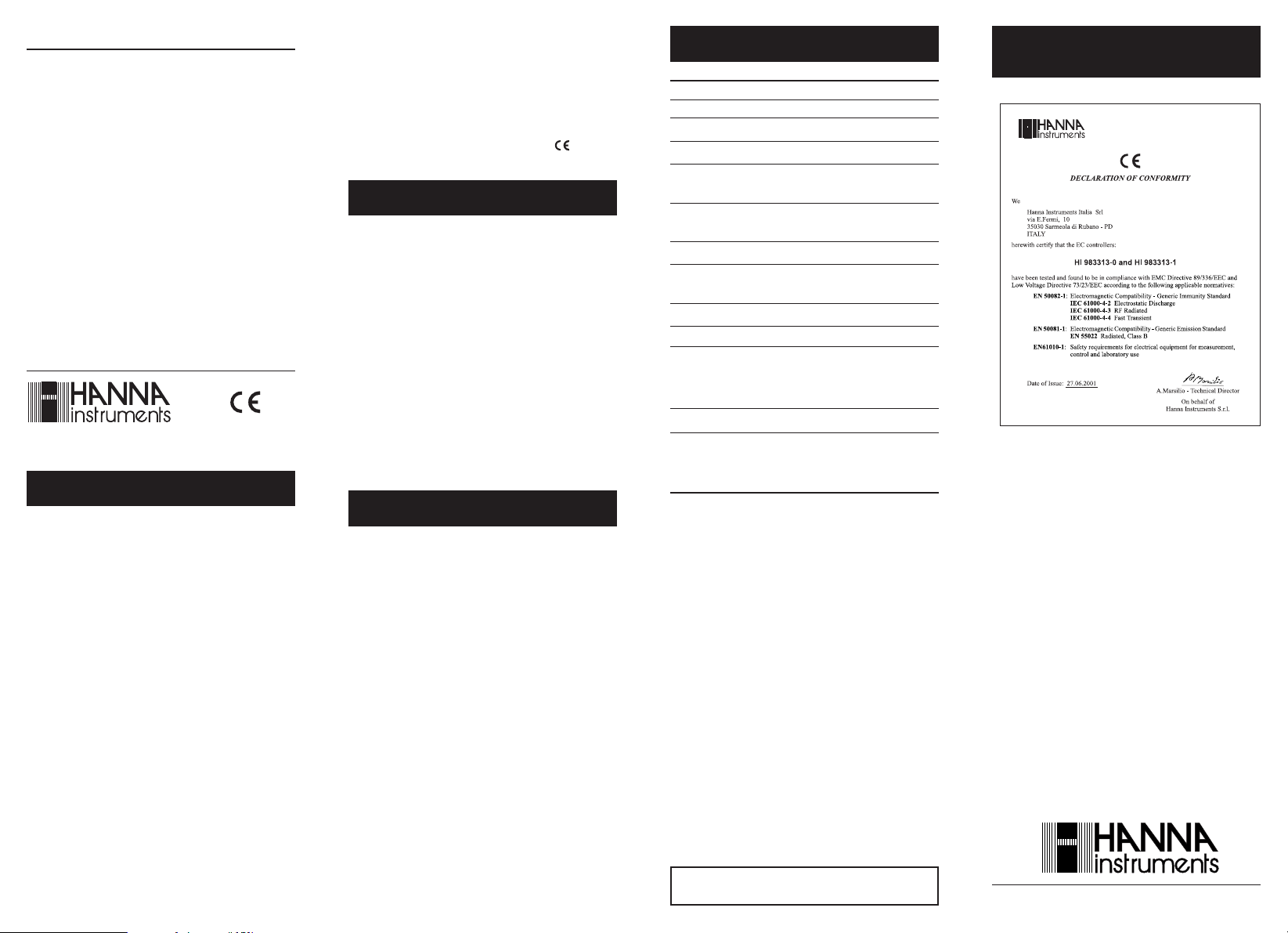
Compliance with the CE Directives
Dear Customer,
Thank you for choosing a Hanna product. This manual will
provide you with the necessary information for the correct
operation of the meter. Please read it carefully before using
the meter. If you need additional technical information, do
not hesitate to e-mail us at tech@hannainst.com.
These instruments are in compliance with the directives.
PRELIMINARY EXAMINATION
Remove the instrument from the packing material and
examine it carefully. If any damage has occurred during
shipment, immediately notify your Dealer or the nearest
Hanna Customer Service Center.
The meter is supplied with:
• Instruction manual;
• Mounting brackets.
Note: Conserve all packing material until the instrument
has been observed to function correctly. Any defective
item must be returned in its original packing.
GENERAL DESCRIPTION
HI 983313-0 and HI 983313-1 are conductivity indicators
and controllers with a relay output designed for simplicity of
use in a wide range of applications.
The two models are panel mounted with membrane keypads on the front panel and an easy-to-read LCD display.
Both meters automatically compensate for the temperature
variation.
The probe is easy to clean and requires little maintenance.
Measurements are highly accurate and the meters can be
calibrated at one point.
Power supply, wiring and selection are made via the plug-
in terminal blocks on the rear panel.
LED indicators on the front panel identify whether the
controller is in set or measurement mode and if alarm is
active.
SPECIFICATIONS
Range 0 to 1999 µS/cm
Resolution 1 µS/cm
Accuracy (@ 20°C) ±2% f.s.
Setpoint Adjustable through multiturn trimmer
Alarm Condition LED ON and alarm contact closed when
measured EC value is higher than setpoint
Alarm Output 2-contact relay, no fuse protected.
5A, 240 VAC, 30 VDC
Probe HI 7634-00 EC/TDS probe
Temp.Compensation Automatic from 5 to 50°C
(41 to 122°F); ß=2%/ºC
Calibration Manual, at one point through trimmer
Calibration Solution HI 7031 (1413 µS/cm)
Power supply: External
HI 983313-0 12 VDC
HI 983313-1 115/230 VAC; 50/60Hz
Dimensions 79 x 49 x 95 mm (3.1 x 1.9 x 3.7”)
Weight:
HI 983313-0 140 g (4.96 oz)
HI 983313-1 250 g (8.85 oz)
CE DECLARATION
OF CONFORMITY
Recommendations for Users
Before using these products, make sure that they are entirely suitable
for the environment in which they are used. Operation of these instruments in residential areas could cause unacceptable interferences to
radio and TV equipment. The metal band at the end of the probe is
sensitive to electrostatic discharges. Avoid touching this metal band at
all times. During operation, ESD wrist straps should be worn to avoid
possible damage to the probe by electrostatic discharges. Any variation
introduced by the user to the supplied equipment may degrade the
instrument’s EMC performance.
To avoid electrical shock, do not use these instruments when voltage at
the measurement surface exceeds 24 VAC or 60 VDC. Use plastic
beakers to minimize any EMC interferences.
To avoid damage or burns, do not perform any measurement in microwave ovens.
ISTR983313R5 12/01
Hanna Instruments reserves the right to modify the design, construction
and appearance of its products without advance notice.
http://www.hannainst.com
Page 2
FUNCTIONAL DESCRIPTION
FRONT PANEL
Keypad
SET To display set
point
MEAS To display
measurement
Trimmers
CAL For calibration
SET To adjust
setpoint
LEDs
SET ON when
LCD displays the set value
MEAS ON when LCD displays the measured value
ALARM ON when alarm contact is activated
REAR PANEL
1. Power Supply:
HI 983313-0 HI 983313-1
12 VDC 115/230 VAC
L1: Positive 230 VAC
L2: Negative 115 VAC
L3: ---- Neutral
L4: ---- Protection Earth
Note: the power input is internally protected by a 400 mA fuse
2. Alarm Contact: A1, A2.
HI 983313
EC CONTROLLER
0 ...1999 µS
ALARM
CAL
SET MEAS
SET
µS
3. Probe Connection: follow the above diagram and connect the
colored wires of probe cable as indicated. It is recommended
to connect the shield (P5) to avoid any interference.
OPERATIONAL GUIDE
POWER CONNECTION
HI 983313-0
Connect a 2-wire power cable to the terminal strip while
paying attention to the correct positive and negative polarities (12 VDC).
HI 983313-1
Connect a 3-wire power cable to the terminal strip while
paying attention to the correct earth, neutral and line
contacts (115/230 VAC).
ALARM CONTACT
Use this contact (maximum 5A, 240VAC, 30VDC) for connection to an alarm or dosing system. The unit acts as a switch
to control an external device.
Notes:
• All external cables connected to the rear panel should
end with wire lugs.
• It is recommended to cover the unused terminals with
insulating tape.
• At start up the meter needs a few seconds to stabilize.
Wait until a stable reading is displayed.
OPERATING THE METER
All operations can be controlled via front panel keys and
trimmers.
“SET” and “MEAS” LEDs light up to indicate which is the
operating function.
Make sure that the meter is calibrated and the Setpoint is
properly selected before performing any measurement.
Attach the probe to the meter. Install the probe in the
fittings or immerse it in the solution to be monitored, while
making sure that metal pins are completely submerged.
Press the “MEAS” key.
The LCD will show the conductivity value of the solution in
µS/cm unit. Any initial variation on readings may be due
to temperature compensation.
The “ALARM” LED will light up when the alarm contact is
closed, to indicate an EC value higher than selected setpoint.
CALIBRATION
Make sure the meter is in the measurement mode (the
“MEAS” LED lights on).
Immerse the probe in HI 7031 (1413 µS/cm) calibration
solution.
Shake briefly and wait for reading to stabilize.
Using a small screwdriver adjust the calibration trimmer
until the meter displays “1413” on the LCD.
SETPOINT
Press the “SET” key. The display will show the default or
previously adjusted value for the setpoint.
Using a small screwdriver, adjust the “SET” trimmer until
the required limit value is displayed.
PROBE MAINTENANCE
To improve probe performance and prolong its life, it is
recommended to clean it regularly.
• Immerse the tip of the probe in HI 7061 Cleaning
Solution at least for one hour.
• If a more thorough cleaning is required, brush the
metal pins with very fine sandpaper.
• After cleaning, rinse the probe with tap water and
recalibrate the meter.
• When not in use, clean the probe before storing it.
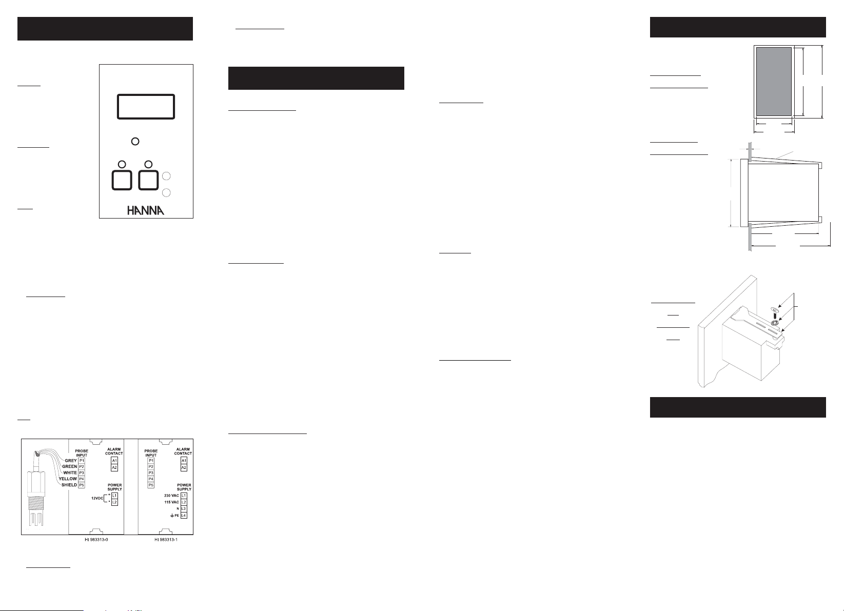
HI 993313 LAYOUT
Front view of the
panel-mounted unit
Side view of the
panel-mounted unit
0.25/4mm
0.01/0.160"
Adjustable location brackets (supplied with the
meter) allow the control-
79mm
3.11"
ler to slide into the cutout
and will hold the unit
securely in place. 95 mm
(3.74") is the minimum
amount of space required to install the controller.
Panel-mounted
unit
assembling
view
42mm
1.65"
49mm
1.93"
76mm
3"
95mm MIN
3.74"
73mm
2.87"
ADJUSTABLE
LOCATION
BRACKET
HI 740146
ACCESSORIES
HI 7634-00 EC/TDS probe
HI 70031P 1413 µS/cm cal. solution, 20 mL sachet (25 pcs)
HI 70031M 1413 µS/cm cal. solution, 230 mL bottle
HI 7061M Electrode cleaning solution, 230 mL bottle
HI 710005 12 VDC power adapter, US plug
HI 710006 12 VDC power adapter, European plug
HI 710012 12 VDC power adapter, Australian plug
HI 710013 12 VDC power adapter, Southern Africa plug
HI 710014 12 VDC power adapter, UK plug
HI731326 Calibration Screwdriver (20 pcs)
HI 740146 Mounting brackets
79mm
3.11"
 Loading...