

Page 1
Instruction Manual
HI 9828
Multiparameter
www.hannainst.com
1
Page 2

2
Page 3

Dear CustomerDear Customer
Dear Customer,
Dear CustomerDear Customer
Thank you for choosing a Hanna Instruments product.
Please read this instruction manual carefully before using the instrument. It will
provide you with the necessary information for correct use of the instrument, as
well as a precise idea of its versatility.
If you need additional technical information, do not hesitate to e-mail us at
tech@hannainst.comtech@hannainst.com
tech@hannainst.com or see the back cover for our worldwide contact list.
tech@hannainst.comtech@hannainst.com
This instrument is in compliance with the
directives.
Hanna Instruments reserves the right to modify the design,
construction and appearance of its products without advance notice.
3
Page 4

TABLE OF CONTENTS
CHAPTER 1- INTRODUCTION
1.1 Preliminary examination .............................................................................. 7
1.2 Model identification .................................................................................... 7
1.3 General description .................................................................................... 8
1.4 Power supply.............................................................................................. 9
1.4.1 Batteries installation .............................................................................. 9
1.4.2 Recharging batteries ............................................................................. 9
1.5 Probe description & installation .................................................................. 10
1.5.1 Sensors description ............................................................................. 10
1.5.2 Sensors specifications ......................................................................... 11
1.5.3 D.O. sensor activation ........................................................................ 12
1.5.4 Installation ......................................................................................... 12
1.6 Specifications ........................................................................................... 13
1.7 Display & keyboard description .................................................................. 17
1.8 Help function ........................................................................................... 18
CHAPTER 2 - MEASUREMENT MODE
2.1 Procedure ................................................................................................ 19
CHAPTER 3 - SYSTEM SETUP
3.1 Measurement setup .................................................................................. 20
3.2 System setup ............................................................................................ 22
3.3 Table of measurement & setup items .......................................................... 26
CHAPTER 4 - CALIBRATION MODE
4.1 Quick calibration ..................................................................................... 28
4.2 pH calibration .......................................................................................... 30
4.2.1 Preparation ........................................................................................ 30
4.2.2 Procedure .......................................................................................... 30
4.2.3 Error list ............................................................................................ 32
4
Page 5

4.3 Dissolved oxygen calibration ..................................................................... 33
4.3.1 Procedure .......................................................................................... 33
4.4 Conductivity calibration ............................................................................ 34
4.4.1 Procedure .......................................................................................... 35
4.5 Atmospheric pressure ................................................................................ 37
4.5.1 Procedure ............................................................................................. 37
4.6 ORP calibration ....................................................................................... 37
4.6.1 Procedure .......................................................................................... 37
4.7 Temperature calibration ........................................................................... 38
4.7.1 Procedure .......................................................................................... 38
CHAPTER 5 - LOGGING MODE
5.1 Logging ................................................................................................... 39
5.1.1 Logging options ................................................................................. 39
5.2 Log data setup ......................................................................................... 40
5.2.1 Lots ................................................................................................... 41
5.2.2 Delete all lots ..................................................................................... 42
5.2.3 Remarks ............................................................................................ 42
5.2.4 Delete all remarks .............................................................................. 43
5.2.5 Tags .................................................................................................. 43
CHAPTER 6 - GLP
6.1 Probe information..................................................................................... 45
6.2 pH .......................................................................................................... 46
6.3 Dissolved oxygen...................................................................................... 46
6.4 Conductivity............................................................................................. 47
6.5 Atmospheric pressure ................................................................................ 47
6.6 ORP........................................................................................................ 48
6.7 Temperature............................................................................................. 48
CHAPTER 7 - PC CONNECTION
7.1 Software installation ................................................................................. 49
7.2 PC connection ......................................................................................... 49
CHAPTER 8 - ERROR MESSAGES................................................................ 51
5
Page 6

APPENDIX
A - PROBE MAINTENANCE ............................................................................ 53
B - ACCESSORIES.......................................................................................... 55
C - WARRANTY.............................................................................................. 57
USER NOTES ............................................................................................ 58
6
Page 7
Chapter 1 - INTRODUCTION
1.1 PRELIMINARY EXAMINATION
Remove the instrument from the packing material and examine it carefully to
make sure that no damage has occurred during shipping. If there is any noticeable damage, notify your Dealer or the nearest Hanna Customer Service Center
immediately.
HI9828HI9828
HI9828 is supplied complete with:
HI9828HI9828
- Multisensor probe (pH/ORP, Conductivity, D.O.)
HI9828-25HI9828-25
-
HI9828-25 quick calibration standard solution, 500 mL
HI9828-25HI9828-25
- Calibration beaker
- Probe maintenance kit
- 4 rechargeable C size, Ni-MH batteries
- Power adaptor and cable
- Cigarette lighter cable
- 5 i-Button
HI7698281HI7698281
-
HI7698281 USB interface cable
HI7698281HI7698281
HI92000HI92000
-
HI92000 Windows® compatible software
HI92000HI92000
- Instruction manual
- Rugged carrying case
©
with holder
NONO
TETE
NO
TE Save all packing materials until you are sure that the instrument func-
NONO
TETE
tions correctly. Any damaged or defective items must be returned in
their original packing materials together with the supplied accessories.
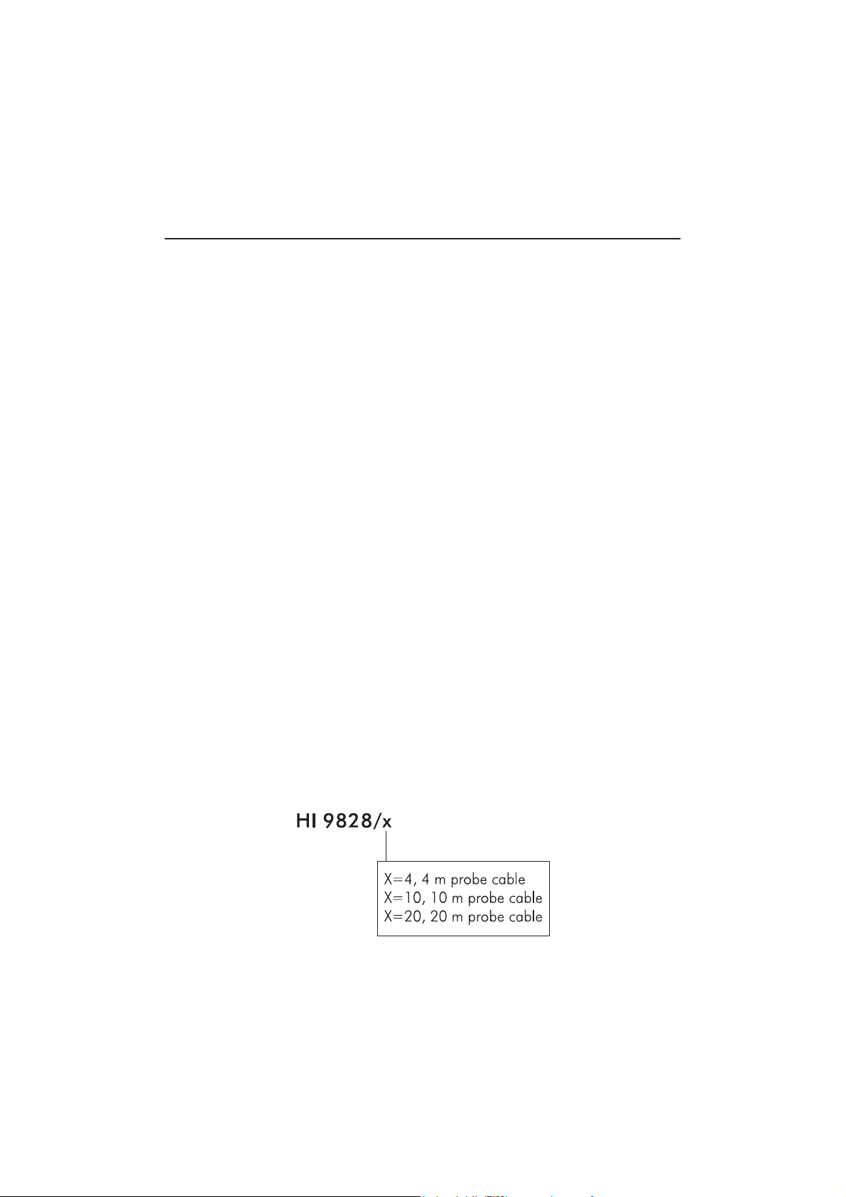
1.2 MODEL IDENTIFICATION
Based on probe cable length, 3 different models are available according to the
following scheme:
Windows® is a registered Trademark of “Microsoft Co.”
7
Page 8

1.3 GENERAL DESCRIPTION
HI 9828HI 9828
HI 9828 is a multiparameter system that benefits from years of experience of
HI 9828HI 9828
Hanna Instruments as a manufacturer of analytical instruments. Waterproof,
resistant and easy to use, it is the ideal solution for field measurements of lakes,
rivers and sea. Thanks to the microprocessor based multisensor probe, it is possible to measure all the parameters necessary to evaluate the water quality, as
dissolved oxygen saturation percentage, conductivity, seawater specific gravity
and other parameters that ensure life in water as pH and temperature. It is also
possible to use the same probe with different meters without the need to recalibrate
the system.
Up to 12 parameters can be enabled and seen on the large graphic display with
backlight. All readings can be memorized and associated to a precise sampling
area thanks to the i-Button
©
system and the remarks that the operator can insert
before or during measurements. The same data can be plotted on the meter and
also downloaded to a PC by means of USB connector and
HI92000HI92000
HI92000 Windows
HI92000HI92000
compatible application for successive elaborations.
The setting menu can be protected by password to avoid not authorized modifications and the help function is always available to explain the selected function,
operation or message.
®
The main features of
HI9828HI9828
HI9828 series include:
HI9828HI9828
• Measurement of dissolved oxygen, pH, ORP, conductivity and related param-
eters, temperature, atmospheric pressure and seawater specific gravity
• Field replaceable sensor modules for DO, EC and pH/ORP
• 5 interface languages: English, Spanish, French, Portuguese, Italian
• Graphical display with backlight
• GLP features
• i-Button
©
system to remark the sampling area
• Up to 60,000 samples stored in 100 different lots
• Four C size Ni-MH rechargeable batteries
• Batteries recharged from mains power supply and from cigarette lighter
• Password protection
8
Page 9
1.4 POWER SUPPLY
HI9828HI9828
HI9828 runs with 4 rechargeable C size, Ni-MH batteries.
HI9828HI9828
On the display the battery symbol visualizes the remaining battery charge. When
this symbol starts blinking, it is necessary to recharge or replace them with new
ones. When the batteries are completely rundown the meter automatically shuts
off to avoid wrong readings.
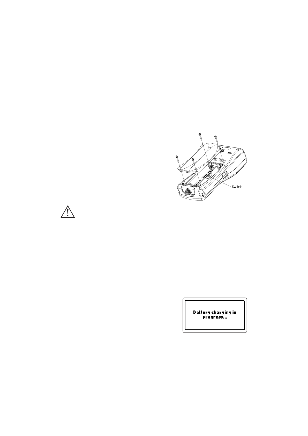
1.4.1 Batteries installation
Battery replacement must only take place in a
nonhazardous area.
Remove the 4 screws on the rear cover of the
instrument and insert the batteries while paying
attention to the correct polarity.
Move the switch down toward the probe connector if using rechargeable batteries. Move the
switch up for alkaline batteries.
Alkaline batteries can explode or leak when attempting to
recharge them with the switch set to down position.
1.4.2 Recharging batteries
HI9828HI9828
HI9828 is supplied with two cables for recharging batteries:
HI9828HI9828
HI710046HI710046
HI710046.
HI710046HI710046
HI710045HI710045
HI710045 and
HI710045HI710045
Mains power supply
In order to recharge batteries from the mains power supply, use
combined with the 12 Vdc adapter.
• With the meter OFF, disconnect the probe.
• Connect
HI710045HI710045
HI710045 to the meter and to the power adapter; connect the
HI710045HI710045
adapter to the mains power supply.
• The message “Battery charging in progress” ap-
pears and then the battery symbol.
• A complete batteries recharging will last about
14 hours.
HI710045HI710045
HI710045
HI710045HI710045
9
Page 10
Cigarette lighter supply
To recharge
HI9828HI9828
HI9828 from a vehicle cigarette lighter supply, use
HI9828HI9828
HI710046HI710046
HI710046.
HI710046HI710046
• Simply connect the cable to the meter and to the car’s cigarette lighter.
• The message “Battery charging in progress” appears on the display, followed
by the battery symbol.
• A complete batteries recharging will last about 14 hours.
NONO
TETE
NO
TE Batteries can also be recharged with the meter ON; if the auto-off
NONO
TETE
feature is enabled, the meter turns off automatically after the set time.
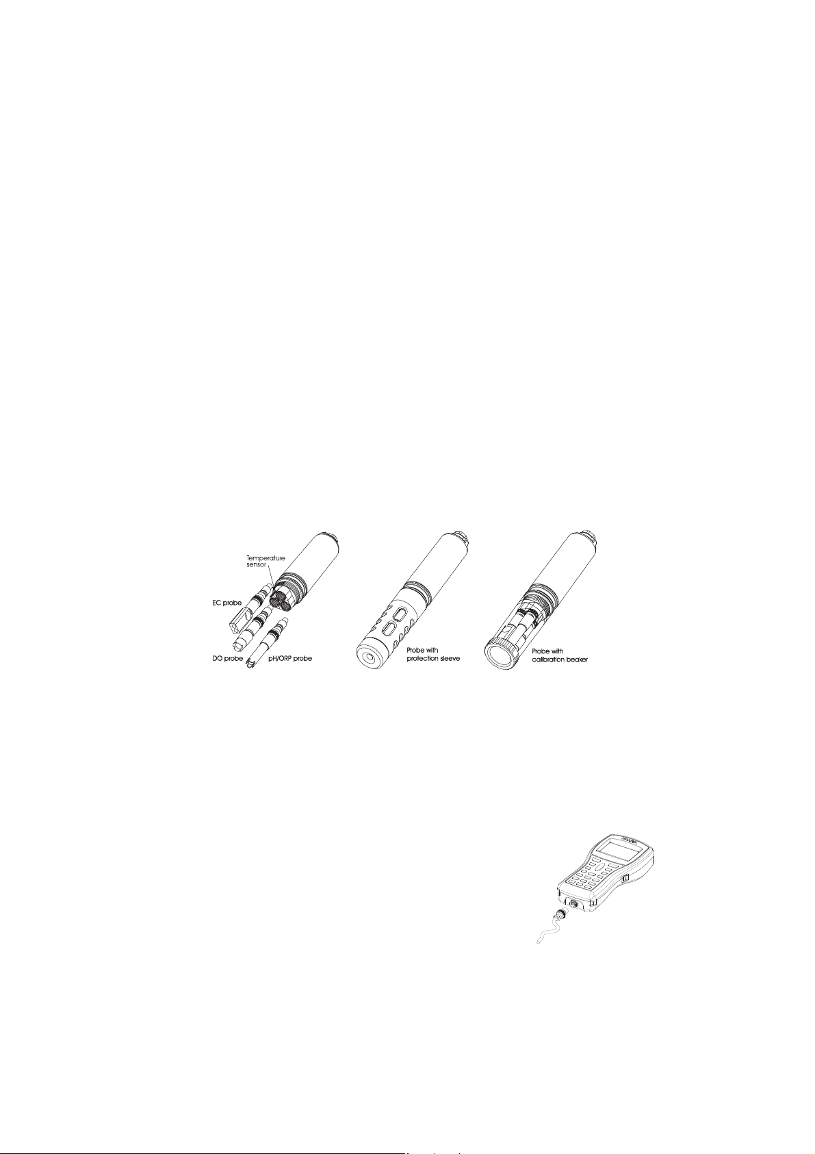
1.5 PROBE DESCRIPTION & INSTALLATION
HI9828HI9828
HI9828 is supplied with the multisensor probe for dissolved oxygen, tempera-
HI9828HI9828
ture, conductivity, pH and redox measurements.
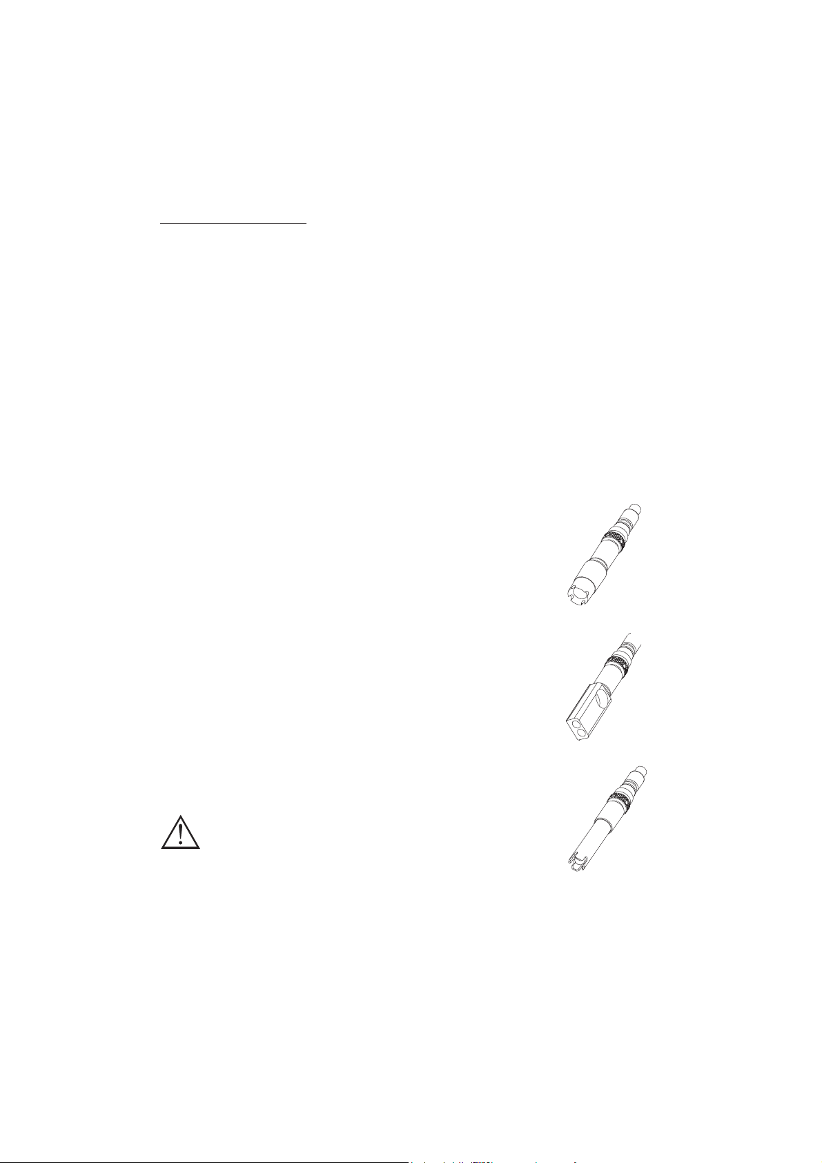
1.5.1 Sensors description
The galvanic D.O. sensor allows to have stable readings in
a few seconds. The thin permeable membrane isolates the
sensor elements from the testing solution, but allows oxygen
to enter. Oxygen that passes through the membrane causes
a current flow, from which the oxygen concentration is determined. Before installing the probe, it is necessary to activate the D.O. sensor; see paragraph 1.5.3 for details.
The conductivity sensor uses the 4-ring technology that allows stable and linear readings without any interference in
the whole range.
The pH/ORP sensor features a glass membrane for pH readings and a Pt sensor for redox measurements.
To avoid clogging problems and ensure a fast response, the
pH bulb must be kept moist at any time. Store the electrode
with few drops of
HI70300HI70300
HI70300 storage solution in the protec-
HI70300HI70300
tive cap.
The EC sensor also works as matching pin
and must be always mounted to have correct pH readings.
For correct redox measurements, the surface of the electrode must be clean and smooth, and a pretreatment procedure should be performed to ensure quick responses.
10
Page 11

Since the Pt/PtO system depends on the pH, the pretreatment of the electrode
may be determined by the pH and the redox potential values of the solution to be
measured.
As a general rule, if the ORP (mV) reading corresponding to the solution pH
value is higher than the values in the table below, an oxidizing pretreatment is
necessary; otherwise perform a reducing pretreatment.
pHpH
mVmV
pHpH
mVmV
pHpH
mVmV
pHpH
mVmV
pH pH
pH
pHpH
mV
mVmV
pH
pHpH
mV
mVmV
pH
pHpH
mV
mVmV
pH
pHpH
mV
mVmV
pH
pH pH
mV mV
mV
mV mV
pHpH
pH
pHpH
mVmV
mV
mVmV
0 990 1 920 2 860 3 800 4 740 5 680
6 640 7 580 8 520 9 460 10 400 11 340
12 280 13 220 14 160
For reducing pretreatment: immerse the electrode for a few minutes in HI 7091L.
For oxidizing pretreatment: immerse the electrode for a few minutes in HI 7092L.
1.5.2 Specifications of sensors
HI769828-0 HI769828-1 HI769828-2 HI769828-3
Sensor Type pH pH/ORP DO EC
Measure Type pH; mV (pH) pH; mV (pH); mV DO% sat; DO conc. EC; TDS;
resistivity; salinity
Measure Range 0.00 to 14.00 0.00 to 14.00 0.0 to 500.0 % 0.000-200.000 mS/cm
±600.0 mV (pH) ±600.0 mV (pH) 0.00 to 50.00 mg/L 0-400000 mg/L
Color Code Red Red White Blue
Materials Tip: glass (pH) Tip: glass (pH); Pt (ORP) Cat/An: Ag/Zn Stainless steel
Junction: cloth Junction: cloth Membrane: PTFE AISI 316
Body: PEI Body: PEI Body: PVC Body: PVC
Electrolyte: gel Electrolyte: gel
Reference: double Reference: double
Maintenance HI 70300 HI 70300 HI 7042S -
Solution (storage) (storage) (refilling)
Dimensions 100 x 14 Ø mm 100 x 14 Ø mm 101 x 16.5 Ø mm 111 x 14 Ø mm
±2000.0 mV 0 to 1.0000 MΩ/cm
0.00 to 70.00 PSU
11
Page 12
1.5.3 D.O. sensor activation
The D.O. probe is shipped dry. To hydrate the probe and prepare it for use proceed as follows:
• Remove the black & red plastic cap. This cap is used for shipping purposes only
and can be thrown away.
• Insert the supplied O-ring in the membrane.
• Rinse the supplied membrane with electrolyte while shaking it gently. Refill with
clean electrolyte. Gently tap the membrane over a surface to ensure that no air
bubbles remain trapped. To avoid damaging the membrane, do not touch it
with your fingers.
• With the sensor facing down screw the cap clockwise to the end of the threads.
Some electrolyte will overflow.
1.5.4 Installation
The multisensor probe can support 3 different electrodes, DO, EC, pH/ORP. To
make easier the installation, the 3 sensors have 3 proper color codes.
For correct sensor installation, proceed as follow:
• Grease the O-ring gaskets.
• Insert the sensor while paying attention to the correct alignment with the corre-
sponding colored connector; fix the sensor by screwing the locking nut with
the supplied tool.
• When all sensors are mounted, screw the protection sleeve for taking mea-
surements or the transparent beaker for calibration.
• With the meter off, connect the probe to the DIN socket on
the bottom of the meter by aligning the pins and pushing
in the plug. Tighten the nut to ensure a good connection.
12
Page 13

1.6 SPECIFICATIONS
TEMPERATURE
RR
angeange
R
ange -5.00 to 55.00 °C;
RR
angeange
23.00 to 131.00 °F; 268.15 to 328.15 K
RR
esolutionesolution
R
esolution 0.01 °C; 0.01 °F; 0.01 K
RR
esolutionesolution
AccuracyAccuracy
Accuracy ± 0.15 °C; ± 0.27 °F; ±0.15 K
AccuracyAccuracy
CalibrationCalibration
Calibration Automatic at 1 custom point
CalibrationCalibration
pHpH
pH
pHpH
RR
angeange
R
ange 0.00 to 14.00 pH; ± 600.0 mV
RR
angeange
RR
esolutionesolution
R
esolution 0.01 pH; 0.1 mV
RR
esolutionesolution
AccuracyAccuracy
Accuracy ± 0.02 pH; ± 0.5 mV
AccuracyAccuracy
CalibrationCalibration
Calibration Automatic 1, 2 or 3 points with 5 memorized
CalibrationCalibration
standard buffers (pH 4.01, 6.86, 7.01, 9.18, 10.01)
or 1 custom buffer
ORP
RR
angeange
R
ange ± 2000.0 mV
RR
angeange
RR
esolutionesolution
R
esolution 0.1 mV
RR
esolutionesolution
AccuracyAccuracy
Accuracy ± 1.0 mV
AccuracyAccuracy
CalibrationCalibration
Calibration Automatic at 1 custom point
CalibrationCalibration
DISSOLVED OXYGEN
RR
angeange
R
ange 0.0 to 500.0 %
RR
angeange
0.00 to 50.00 mg/L
RR
esolutionesolution
R
esolution 0.1 %
RR
esolutionesolution
0.01 mg/L
AccuracyAccuracy
Accuracy 0.0 to 300.0 %: ± 1.5 % of reading
AccuracyAccuracy
or ± 1.0% whichever is greater;
300.0 to 500.0 %: ± 3% of reading
0.00 to 30.00 mg/L: ± 1.5 % of reading
or 0.10 mg/L whichever is greater;
30.00 mg/L to 50.00 mg/L: ± 3% of reading
CalibrationCalibration
Calibration Automatic 1 or 2 points at 0, 100 % or 1 custom point
CalibrationCalibration
13
Page 14

CONDUCTIVITY
RR
angeange
R
ange 0.000 to 200.000 mS/cm
RR
angeange
(actual EC up to 400 mS/cm)
RR
esolutionesolution
R
esolution
RR
esolutionesolution
Manual 1 µS/cm; 0.001 mS/cm; 0.01 mS/cm; 0.1 mS/cm; 1 mS/cm
Automatic 1 µS/cm from 0 to 9999 µS/cm
0.01 mS/cm from 10.00 to 99.99 mS/cm
0.1 mS/cm from 100.0 to 400.0 mS/cm
Automatic mS/cm 0.001 mS/cm from 0.000 to 9.999 mS/cm
0.01 mS/cm from 10.00 to 99.99 mS/cm
0.1 mS/cm from 100.0 to 400.0 mS/cm
AccuracyAccuracy
Accuracy ±1 % of reading or ±1 µS/cm whichever is greater
AccuracyAccuracy
CalibrationCalibration
Calibration Automatic at 1 point with 6 memorized standards
CalibrationCalibration
(84 µS/cm, 1413 µS/cm, 5.00 mS/cm, 12.88 mS/cm,
80.0 mS/cm, 111.8 mS/cm) or custom point
RESISTIVITY
RR
angeange
R
ange 0 to 999999 Ω·cm;
RR
angeange
(depending on measurement setup) 0 to 1000.0 kΩ·cm;
0 to 1.0000 MΩ·cm
RR
esolutionesolution
R
esolution Depending on resistivity reading
RR
esolutionesolution
CalibrationCalibration
Calibration Based on conductivity or salinity calibration
CalibrationCalibration
TDS
RR
angeange
R
ange 0 to 400000 mg/L or ppm;
RR
angeange
(the maximum value depends on the TDS factor)
RR
esolutionesolution
R
esolution
RR
esolutionesolution
Manual 1 mg/L (ppm); 0.001 g/L (ppt);
0.01 g/L (ppt); 0.1 g/L (ppt); 1 g/L (ppt)
Automatic 1 mg/L (ppm) from 0 to 9999 mg/L (ppm)
0.01 g/L (ppt) from 10.00 to 99.99 g/L (ppt)
0.1 g/L (ppt) from 100.0 to 400.0 g/L (ppt)
Automatic g/L (ppt) 0.001 g/L (ppt) from 0.000 to 9.999 g/L (ppt)
0.01 g/L (ppt) from 10.00 to 99.99 g/L (ppt)
0.1 g/L (ppt) from 100.0 to 400.0 g/L (ppt)
AccuracyAccuracy
Accuracy ±1 % of reading or ±1 mg/L (ppm) whichever is greater
AccuracyAccuracy
CalibrationCalibration
Calibration Based on conductivity or salinity calibration
CalibrationCalibration
14
Page 15

SALINITY
RR
angeange
R
ange 0.00 to 70.00 PSU (extended Practical Salinity Scale)
RR
angeange
RR
esolutionesolution
R
esolution 0.01 PSU
RR
esolutionesolution
AccuracyAccuracy
Accuracy ±2% of reading or ±0.01 PSU whichever is greater
AccuracyAccuracy
CalibrationCalibration
Calibration 1 custom point
CalibrationCalibration
SEAWATER SPECIFIC GRAVITY
RR
angeange
R
ange 0.0 to 50.0 σt, σ0, σ
RR
angeange
RR
esolutionesolution
R
esolution 0.1 σt, σ0, σ
RR
esolutionesolution
AccuracyAccuracy
Accuracy ± 1σt, σ0, σ
AccuracyAccuracy
CalibrationCalibration
Calibration Based on conductivity or salinity calibration
CalibrationCalibration
15
15
15
ATMOSPHERIC PRESSURE
RR
angeange
R
ange 450 to 850 mmHg;
RR
angeange
17.72 to 33.46 inHg;
600.0 to 1133.2 mbar;
8.702 to 16.436 psi;
0.5921 to 1.1184 atm;
60.00 to 113.32 kPa
RR
esolutionesolution
R
esolution 0.1 mmHg; 0.01 inHg; 0.1 mbar
RR
esolutionesolution
0.001 psi; 0.0001 atm; 0.01 kPa
AccuracyAccuracy
Accuracy ± 3 mmHg within ± 15 °C
AccuracyAccuracy
from the temperature during calibration
CalibrationCalibration
Calibration Automatic at 1 custom point
CalibrationCalibration
15
Page 16

GENERAL CHARACTERISTICS
TT
emperature Compensationemperature Compensation
T
emperature Compensation automatic from -5 to 55 °C (23 to 131 °F)
TT
emperature Compensationemperature Compensation
LL
ogging Memoryogging Memory
L
ogging Memory Up to 60,000 samples with 13 measurements each*
LL
ogging Memoryogging Memory
LL
ogging Intervalogging Interval
L
ogging Interval From 1 second to 3 hours
LL
ogging Intervalogging Interval
PC InterfacePC Interface
PC Interface USB (with HI 92000 software)
PC InterfacePC Interface
WW
aterproof Paterproof P
W
aterproof P
WW
aterproof Paterproof P
EnvironmentEnvironment
Environment 0 to 50 °C (32 to 122 °F); RH 100 %
EnvironmentEnvironment
PP
ower Supplyower Supply
P
ower Supply 4 x 1.5 V alkaline C cells (approximately 150
PP
ower Supplyower Supply
rotectionrotection
rotection Meter IP67, Probe IP68
rotectionrotection
hours of continuous use, without backlight) or
4 x 1.2 V rechargeable C cells (approximately 70 hours
of continuous use, without backlight)
DimensionsDimensions
Dimensions
DimensionsDimensions
Meter 221 x 115 x 55 mm (8.7 x 4.5 x 2.2”)
Probe L = 270 (10.6”), dia = 46 mm (1.8”)
WW
eighteight
W
eight
WW
eighteight
Meter 750 g (26.5 oz.)
Probe 750 g (26.5 oz.)
* Without remarks. When using remarks the maximum number of samples decreases but in practical cases
it will never be less than 50,000.
16
Page 17
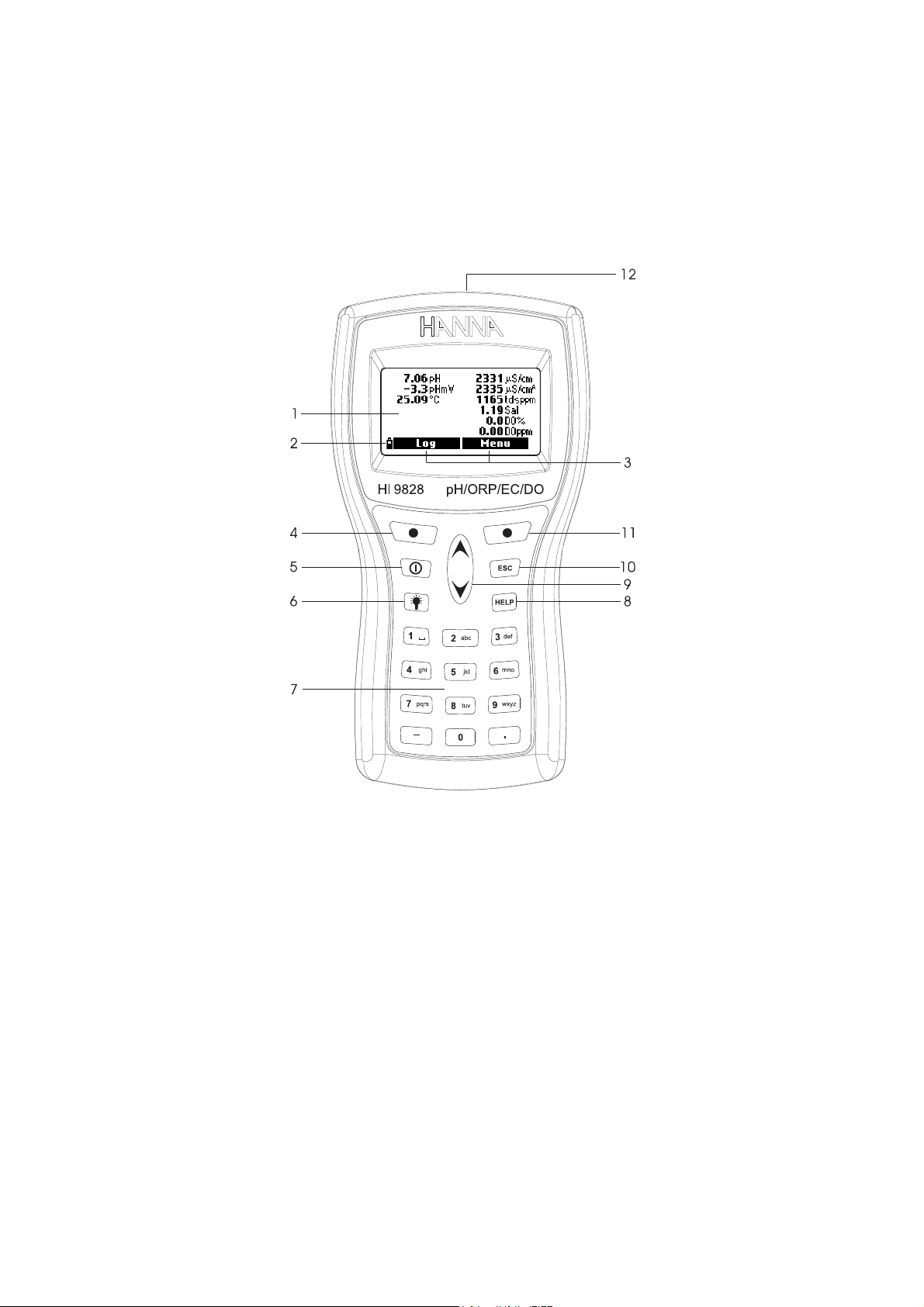
1.7 DISPLAY & KEYBOARD DESCRIPTION
1. Display
2. Battery level indicator
3. Softkey functions
4. Left softkey: function defined on display
5. On/Off key: to turn on and off the meter
6. Backlight: to activate the backlight
7. Alphanumeric keyboard: to insert alphanumeric codes
8. HELP key: to have information about the shown screen
9. Arrow keys: to scroll between options
10. ESC key: to go back to the previous screen
11. Right softkey: function defined on display
12. Tag reader
17
Page 18

1.8 HELP FUNCTION
HI9828HI9828
HI9828 is provided with the HELP function, useful to have short information
HI9828HI9828
regarding the displayed screen. Simply press the HELP key and an information
window will appear.
For longer messages press the arrow keys to scroll.
To escape from the help window press again the HELP key or ESC.
18
Page 19

Chapter 2 - MEASUREMENT MODE
HI9828HI9828
HI9828 can read at the same time different parameters from the same probe.
HI9828HI9828
As described in the previous section, up to 3 sensors can be mounted on the
probe.
2.1 PROCEDURE
• Connect the probe to the meter and carefully fix the protection sleeve to the
probe.
• Immerse the probe into the sample while paying attention to avoid stones.
• Turn the meter on by pressing the On/Off key. The display will show “HANNA
HI9828”, the firmware version and then enters the measurement mode.
• The meter displays the readings for all the enabled parameters. See Chapter 3
for details.
• Press LOG to store the readings or MENU to enter in the main menu. See
Chapter 5 for details.
NONO
TETE
NO
TE If the meter does not find the probe, the message “Probe disconnected!”
NONO
TETE
appears. In this case only “Menu” softkey is available and only the functions that not require any reading are active.
It is possible to enable up to 12 measurements at the same time. Based
on the number of enabled parameters, the display graphical resolution
changes: the lower the number of parameters, the bigger the size of
the digits.
A small “A” letter added to µS/cm or mS/cm units, refers to actual conductivity value, i.e. the conductivity reading with no temperature compensation.
When a measurement is out of range, the nearest full scale value will
slowly and continuously blink.
By pressing the lamp key, the backlight turns on and off. After one minute
with no key pressed, the backlight turns off automatically.
19
Page 20

Chapter 3 - SETUP MODE
A few parameters have to be set before taking any measurements. In the main
menu two setup items are available: “Measurement” and “System”.
The measurement setup allows to set the displayed readings and their units,
while the system setup is used to set the system parameters, as the interface
language, date and time, LCD contrast, acoustical signals, etc.
3.1 MEASUREMENT SETUP
• Switch the meter on by pressing On/Off.
After the initialization has been completed, the
meter enters the measurement mode. The active
softkeys are LOG and MENU.
• Press MENU, select “Measurement Setup” using the arrow keys, then press OK.
• The display shows the complete list of measurable parameters.
• To select a parameter, scroll with the arrow keys.
It is possible to enable or disable each parameter. A checked box or the measure
unit means that the parameter is enabled. Press the right softkey to enable or
disable the parameter.
For some parameters it is also possible to select the measure unit and the resolution by pressing the UNIT or RESOLUTION softkey.
NONO
TETE
NO
TE If the password is enabled, the meter will ask to insert it prior to change
NONO
TETE
the first parameter.
Temperature
The user can select the measure unit: K, °F or °C.
20
Page 21

pH, mV of pH Input, ORP, D.O. % Saturation, Salinity
These parameters can only be enabled or dis-
abled; the measure unit and the resolution are
fixed.
D.O. concentration
It is possible to select ppm or mg/L measure unit.
Conductivity and Actual Conductivity
It is possible to select among the following op-
tions: Auto (autoranging both µS/cm and mS/
cm ranges), 1 µS/cm, 0.001 mS/cm, 0.01 mS/
cm, 0.1 mS/cm, 1 mS/cm, Auto mS (autoranging for mS/cm ranges).
NONO
TETE
NO
TE The actual conductivity is the conductivity reading with no temperature
NONO
TETE
compensation.
Resistivity
It is possible to select Ω·cm, kΩ·cm or MΩ·cm.
TDS
It is possible to select among the following op-
tions: Auto (autoranging both ppm (mg/L) and
ppt (g/L) ranges), 1 ppm (mg/L), 0.001 ppt (g/
L), 0.01 ppt (g/L), 0.1 ppt (g/L), 1 ppt (g/l), Auto
ppt (g/L) (autoranging for ppt (g/L) ranges).
NONO
TETE
NO
TE
NONO
For setting ppm or mg/L, see paragraph 3.2 “System Setup”.
TETE
Seawater specific gravity
This value is a widely used parameter for seawater; it is similar to density mea-
surement and it is an expression of salt content in water.
It depends on water
pressure, temperature and salinity.
In the seawater specific gravity menu it is possible to select the reference tem-
perature: σ
, σ0 and σ15 (i.e. current temperature, t=0°C and t=15°C).
t
Atmospheric pressure
It is possible to select among the following mea-
sure units: atm, kPA, mmHg, inHg, mbar, psi.
21
Page 22

NONO
TETE
NO
TE A maximum of 12 measurements can
NONO
TETE
be displayed simultaneously. A warning
message appears if trying to enable
more than 12 measurements.
3.2 SYSTEM SETUP
• From measurement mode, press MENU, select “System Setup” using the arrow
keys and then press OK.
• To select a parameter, scroll with the arrow keys to highlight it and then press
MODIFY.
NONO
TETE
NO
TE If the password is enabled, the meter will ask to insert it prior to change
NONO
TETE
the first parameter.
Language
The display language can be selected among the
following available options: English, Spanish,
French, Portuguese and Italian. The language
selection can be modified by pressing the MODIFY
softkey.
ID
The meter can be labelled with an identification
code: press MODIFY and a text box will be displayed. Use the keyboard to insert the desired alphanumeric code and then press OK. A maximum of 25 characters can be used.
Date
Select the desired date format by pressing repeat-
edly FORMAT. The available formats are: DD/
MM/YYYY, YYYY-MM-DD and MM/DD/YYYY.
Use the keyboard to insert the date and then press
OK.
Time
Select the desired time format by pressing repeatedly FORMAT. The available
formats are: hh:mm:ss (24 hours) and hh:mm:ss (12 hours).
22
Page 23

Use the keyboard to insert the time and then press OK.
To choose AM or PM, press A or P on the keyboard after inserting the time.
Auto off
The meter shuts off automatically if no keys are
pressed for the set time. By pressing the MODIFY
softkey it is possible to select the desired option
for this feature: NO (disabled), 5, 10, 15, 20,
30 or 60 minutes.
Log interval
Set the logging time interval from 1 second to 3 hours.
Reference temperature
For conductivity readings, a reference tempera-
ture for the displayed value has to be set. The
available options are 20°C and 25°C. Press the
MODIFY softkey to select the desired option.
Temperature coefficient
The temperature coefficient can be set from
0.00%/°C (no temperature compensation) to
6.00%/°C. Press MODIFY and then use the
keyboard to insert the desired value. The left arrow softkey allows to shift the cursor. To confirm
the value press OK.
TDS factor
The conversion factor can be set from 0.00 to
1.00. Usually for strong ionic solutions the fac-
tor is 0.5 and for weak ionic solutions, as nutritive solutions, is 0.7.
To set this parameter, press MODIFY, insert the
value and then confirm by pressing OK.
23
Page 24

TDS unit
TDS readings can be displayed in ppm-ppt or mg/L-g/L unit. Press MODIFY to
select the desired option.
Average length
In order to obtain an average and more repre-
sentative measurement with unstable samples, set
a reading repetition number for the displayed
parameters.
To select the desired average length, press
MODIFY. The value can be set from 1 to 30.
Key beep
If enabled, the meter emits an acoustical signal
every time a key is pressed.
Error beep
If enabled, the meter emits an acoustical signal
every time a wrong key is pressed, or when some
particular errors occur.
Decimal separator
It is possible to select the type of decimal separa-
tor: dot or comma; press MODIFY to select the
desired symbol.
LCD contrast
For setting the LCD contrast, select the corre-
sponding setup item and press MODIFY. An horizontal bar will be displayed. Use the arrow keys
to modify the contrast and then press OK.
Password
To enable the password proceed as follows:
• Press MODIFY to select the password setup item.
• Insert the desired password in the text box and press OK.
NONO
TETE
NO
TE While typing, the characters are masked with “*” (star) symbol.
NONO
TETE
• The meter will ask to confirm. Type again the same password and then press
OK to confirm.
24
Page 25

• The meter returns to the “System Setup” menu and the checkbox near the
password entry is signed.
To disable the password proceed as follows:
• Press MODIFY to select the password setup item.
• Insert the password and then press DISABLE. “NO” will appear in the text box.
• Press OK to confirm.
Restore factory settings
It is possible to reset the “System Setup” and “Measurement Setup” parameters to
their default values.
• Select the “Restore factory settings” item and
press OK.
• The meter will ask to confirm: press YES to
confirm or NO to escape.
NONO
TETE
NO
TE To quit the system setup mode at any time, press ESC. For all setup
NONO
TETE
items, if the selection is not confirmed, the previous setting will be kept.
25
Page 26

3.3 TABLE OF MEASUREMENT AND SETUP ITEMS
Measurement SetupMeasurement Setup
Measurement Setup
Measurement SetupMeasurement Setup
Item Description Default value Valid Values
Temperature Temperature unit °C K; °C; °F;
pH pH measure 55;
mV of pH input mV of pH readings 55;
ORP Redox measure 55;
D.O. % saturation Dissolved oxygen measure 55;
D.O. concentration Dissolved oxygen measure ppm ppm; mg/L;
Conductivity Electrical conductivity Auto ; Auto; 1 µS; 0.001 mS;
measure 0.01 mS; 0.1 mS; 1 mS; Auto mS
Actual conductivity No temperature compensated Auto ; Auto; 1 µS; 0.001 mS;
conductivity measure 0.01 mS; 0.1 mS; 1 mS; Auto mS
Resistivity Resistivity measure MΩ·cm Ω·cm; kΩ·cm; Ω·cm
TDS Total dissolved solids Auto ; Auto; 1 ppm; 0.001 ppt;
measure 0.01 ppt; 0.1 ppt; 1 ppt; Auto ppt
Salinity Salinity measure 55;
Seawater specific gravitySpecific gravity measure σ
Atmospheric pressure Atm. pressure measure ; mmHg; inHg; mbar;
t
; σt; σ0; σ
psi; atm; kPa
15
System SetupSystem Setup
System Setup
System SetupSystem Setup
Item Description Default value Valid values
Language Interface language English English; Español; Français;
Português; Italiano
ID Meter identification code - Max 25 characters
Date Update calendar YYYY-MM-DD YYYY-MM-DD;
MM/DD/YYYY;
DD/MM/YYYY
Time Update clock hh:mm:ss (24 hours) hh:mm:ss (12 hours);
hh:mm:ss (24 hours)
Auto-off (min) Auto shut-off after a 5 min NO; 5; 10; 15;
period of non use 20; 30; 60 min
Log interval Period between 2 subsequent 00:00:01 00:00:01 to 03:00:00
automatic records
26
Page 27

Ref. temperature Reference temperature for 25°C 20°C; 25°C
conductivity measurements
Temp. coefficient Temperature coefficient for 1.90%/°C 0.00 to 6.00%/°C
conductivity measurements
TDS factor Conversion factor from 0.50 0.00 to 1.00
conductivity to TDS readings
TDS unit Measure unit for TDS ppm-ppt ppm-ppt; mg/L-g/L
Average length Number of readings for 01 1 to 30
average value calculation
Key beep Acoustic signal for key pressed 55 ;
Error beep Acoustic signal for wrong 55 ;
key pressed
Decimal separator Symbol used for decimal separator . . ; ,
of displayed numbers
LCD contrast Contrast for the LCD 8 0 to 15
Password Password insertion - Max 25 characters
27
Page 28

Chapter 4 - CALIBRATION MODE
HI9828HI9828
HI9828 allows to perform six different types of calibration, one for each param-
HI9828HI9828
eter and also a quick single-point calibration for some parameters.
The calibration data are stored in the non volatile probe memory, so that the
same probe can be used with different meters without needing recalibration.
• To perform a calibration, select “Calibration”
in the main menu with the arrow keys and then
press OK.
NONO
TETE
NO
TE If the password is enabled and the latest
NONO
TETE
function displayed was not a password
protected feature, the meter will ask to
insert the password.
• Select the calibration type with the arrow keys and then press OK.
The available options are:
Quick calibration (single point procedure to calibrate the D.O. saturation, pH
and conductivity ranges), pH, D.O., conductivity, atmospheric pressure, ORP and
temperature.
4.1 QUICK CALIBRATION
The quick calibration feature allows a fast and easy calibration of the multiparameter probe on the field, using only one solution (
• Fill the calibration beaker with the
• Screw the calibration beaker on the probe body. Some solution will overflow.
• Wait a few minutes to stabilize.
• In “Calibration” menu, select the “Quick calibration” option and press OK.
• A 3-item (pH, Conductivity and Dissolved Oxygen) screen appears, “pH” starts blinking and
the “Not ready” message is shown on the lower
part of the window.
28
HI9828-25HI9828-25
HI9828-25 calibration solution.
HI9828-25HI9828-25
HI9828-25HI9828-25
HI9828-25).
HI9828-25HI9828-25
Page 29

• When the measure is stable, “Ready” is shown.
Press CONFIRM to store the value.
• The messages “Storing data on probe, please
wait...” and “Updating GLP data, please wait
...” appear.
NONO
TETE
NO
TE If pH calibration is not required, the meter allows to skip to the EC quick
NONO
TETE
calibration, by pressing the SKIP soft key.
If the pH sensor is missing the message “pH sensor not installed! Skip to
conductivity calibration” appears.
• After the pH calibration is completed, the
“Conductivity” option will blink.
• When the measure is stable, “Ready” appears.
Press CONFIRM to store the value.
• The messages “Storing data on probe, please
wait...” and “Updating GLP data, please wait ...” appear.
NONO
TETE
NO
TE If EC calibration is not required, skip to the DO quick calibration, by
NONO
TETE
pressing the SKIP soft key.
• The message “Empty the beaker. Shake the
probe and put it in the beaker again” appears.
• Unscrew the calibration beaker and remove
the solution.
• To dry the probe shake it as you would do with a clinical thermometer. Pay
attention that no drops are present on the DO sensor.
NONO
TETE
NO
TE To avoid sensor damages, do not use paper to dry the probe.
NONO
TETE
• Screw back the calibration beaker on the probe body.
• Wait for reading to stabilize and then press OK to close the displayed message.
• When the measurement is stable, the message “Ready” appears. Press CONFIRM to store the value.
• The messages “Storing data on probe, please wait...” and “Updating GLP data,
please wait...” appear.
• The 3-calibration-item screen appears again
and the check box corresponding to the calibrated parameters will be marked.
• Press OK to return to the calibration menu.
NONO
TETE
NO
TE To quit any quick calibration procedure,
NONO
TETE
press ESC at any time.
29
Page 30

4.2 pH CALIBRATION
Calibrate the meter often, especially if high accuracy is required.
Selecting pH calibration the display shows two options: “Calibrate pH” and “Clear old calibration”.
If “Calibrate pH” is selected, it is possible to perform a new calibration at 1, 2 or 3 points with
standard buffers (pH 4.01, 6.86 or 7.01, 9.18 or
10.01) or a single calibration with custom buffer.
If “Clear old calibration” is selected, all calibration data will be deleted and the
default data restored.
NONO
TESTES
NO
TES Old calibration data have to deleted every time the pH electrode is
NONO
TESTES
replaced and after a cleaning procedure.
When a 3-point calibration is performed, all the old data are overwritten, while with a 1 or 2-point calibration procedure the meter will use
the previous data stored with the last 3-point calibration for the missing
points.
4.2.1 Preparation
Pour small quantities of selected buffer solutions into clean beakers. If possible,
use plastic beaker to minimize EMC interferences. To minimize cross contamination, use two beakers for each buffer solution: the first one for rinsing the electrode and the second one for calibration.
4.2.2 Procedure
The current measured value is shown on the primary display and the buffer value is displayed in
the secondary one.
Press the BUFFER softkey to change the buffer
value or insert a custom buffer.
1, 2 or 3-point calibration
• Immerse the probe into the selected buffer and
stir gently. The current pH value, the buffer
value and “Not ready” are displayed.
• When the reading is stable and close to the
selected buffer value, the display shows
“Ready”.
30
Page 31

• Press CONFIRM to accept the value or BUFFER to select another buffer using
the arrow keys.
• After the first calibration point is confirmed, immerse the probe in the second
buffer solution and stir gently.
• When the reading is stable and close to the selected buffer, the display shows
the message “Ready”.
• Press CONFIRM to accept the value or BUFFER to change the buffer.
• After the second calibration point is confirmed, proceed by immersing the probe
in the third buffer solution, stirring gently and waiting for stable reading.
• When the calibration is completed, the display shows the following messages:
“Storing data on probe, please wait...”, “Updating GLP data, please wait ...”
and “Calibration completed”.
• Press OK to return to the calibration menu.
• To return to the main menu, press ESC repeatedly.
NONO
TETE
NO
TE The user can terminate the pH calibration mode at any time, by press-
NONO
TETE
ing the ESC key.
Custom buffer calibration
HI 9828 allows a single point procedure to cali-
brate with a custom buffer value.
• Select this option by pressing BUFFER and then
CUSTOM keys while the meter is waiting for
stable reading.
• The display shows a window with a text box for inserting the desired custom
value. The valid range for custom buffer is 0.00 to 14.00 pH.
31
Page 32

4.2.3 Error list
If the meter does not accept a pH calibration point, a short message is displayed
to indicate the possible error source. See for example the following screens:
These are the available messages:
• “Input out of scale”: the pH value is out of scale.
• “Wrong buffer”: this message means that the difference between the pH reading and the selected buffer is too big. Check if the proper calibration buffer has
been selected.
• “Invalid temperature”: this message means that the buffer temperature is outside the allowed range.
• “Wrong & Contaminated buffer / Check electrode”: this message means that
the buffer is contaminated or the electrode is broken or very dirty.
• “Wrong & Check electrode / Clean electrode”: this message means that the
electrode is broken or very dirty.
• “Wrong & Clear old calibration”: this message indicates an erroneous slope
condition. This message appears if the slope between current and previous
calibration points exceeds the slope window (80% to 110%). Press the CLEAR
sofkey to clear the old data and continue the calibration procedure, or press
ESC to quit the pH calibration mode.
32
Page 33

4.3 DISSOLVED OXYGEN CALIBRATION
If D.O.% saturation range is calibrated, D.O. concentration range will also be
calibrated, and vice-versa.
The D.O.% saturation value is referred to the D.O. concentration in air (100%).
For this reason it is recommended to calibrate the probe near the area where the
measurements will be taken.
Also note that the D.O. concentration values are based on D.O.% saturation,
temperature, salinity and atmospheric pressure. It is recommended to use a standard solution or a reference D.O. meter to compare readings during calibration.
The calibration of D.O.% saturation range can be performed at 1 or 2 standard
points (0% and 100%), or at a single custom point (50 to 500%).
The calibration of D.O. concentration range can be performed at a single custom point (4 to 50 mg/L).
4.3.1 Procedure
Choose the D.O. calibration mode in the main
calibration menu, then select the calibration type
using the arrow keys and confirm by pressing OK.
D.O. % saturation
This calibration starts by default with 100 %.
• Fill the calibration beaker with approximately 4
mm (5/32”) of distilled water and screw it on
the probe.
• The message NOT READY is displayed until a
stable reading is reached.
• To change the standard calibration point, press
the CAL. POINT softkey and select the desired
standard point.
• To insert a different calibration value, press CAL.
POINT and then CUSTOM. Insert the desired
value using the keyboard.
• When the reading is stable, READY and CONFIRM appear. Press CONFIRM to
store the calibration point.
• After the first calibration point is confirmed, put the probe in a zero oxygen
standard solution and wait for stable reading.
33
Page 34

• Press CONFIRM to store the calibration point.
• The following messages will appear: “Storing data on probe, please wait...”,
“Updating GLP data, please wait ...” and “Calibration completed”.
• Press OK to return to the calibration menu.
• To return to the main menu, press ESC repeatedly.
NONO
TETE
NO
TE The user can perform a single point calibration with standard values.
NONO
TETE
To abort the calibration press ESC after the first point is accepted.
If the D.O. input is not within the acceptable range, the message “IN-
VALID INPUT” is displayed.
D.O. concentration
A solution with known D.O. concentration is
needed to calibrate the D.O. concentration
range.
• From D.O. calibration menu, select DO concentration and insert the known value and press
OK.
• When the reading is stable, press CONFIRM to accept the value.
• When the messages “Storing data on probe, please wait...”, “Updating GLP
data, please wait ...” and “Calibration completed” appear, the calibration is
completed. To return to the main calibration menu, press OK
• To return to the main menu, press ESC repeatedly.
4.4 CONDUCTIVITY CALIBRATION
For a correct conductivity calibration the probe sleeve must be always inserted.
The conductivity calibration menu includes 3 different type of calibration: Conductivity, Actual
conductivity and Salinity.
The “Conductivity” option allows a single point
calibration with a standard solution selectable
by the user. This calibration is temperature compensated.
The “Actual conductivity” option allows a single point calibration with a custom
conductivity solution of known actual value (not temperature compensated).
The “Salinity” option allows calibration with a standard salinity solution.
34
Page 35

The 3 options are related, so that one of this calibration procedure also calibrate
the two remaining ranges.
NONO
TETE
NO
TE For correct EC readings it is recommnded to calibrate using a standard
NONO
TETE
solution with a conductivity value close to the sample being measured.
4.4.1 Procedure
After choosing the conductivity calibration mode in the main calibration menu,
select the type of calibration with the arrow keys and then press OK.
Conductivity
• Select the “Conductivity” option and press OK to confirm.
• Fill a beaker with a standard conductivity solution (see “Accessories” section for
choosing the proper HANNA solution).
• Immerse the probe in the solution and wait for the stable reading. The probe
sleeve must be inserted.
• The primary display shows the actual reading and the secondary one the standard value.
• To change the standard value, press CAL. POINT. The available values of standard solutions are displayed: 0 µS/cm, 84 µS/cm, 1413 µS/cm, 5.00 mS/cm,
12.88 mS/cm, 80.0 mS/cm and 111.8 mS/cm.
• Press CUSTOM to insert a custom value (compensated conductivity value).
Choose “Resolution” to select the desired resolution.
• When the reading is stable, press CONFIRM to store the value.
• After confirmation, the following messages are displayed: “Storing data on
probe, please wait...”, “Updating GLP data, please wait...”, “Calibration complete”.
• Press OK to return to the main calibration menu.
• To return to the main menu, press ESC repeatedly.
35
Page 36

Actual Conductivity
• Select the “Actual conductivity” option and
press OK to confirm.
• Insert the custom value and set its resolution.
• Immerse the probe in the conductivity solution
and wait for stable reading. The probe sleeve
must be inserted.
• When the reading is stable, press CONFIRM to store the value.
• After confirmation, the following messages are displayed: “Storing data on
probe, please wait...”, “Updating GLP data, please wait...”, “Calibration complete”.
• Press OK to return to the main calibration menu.
• To return to the main menu, press ESC repeatedly.
Salinity
• Select the “Salinity” option and press OK.
• Insert the salinity value of the custom calibration solution.
• Immerse the probe in the solution and wait for
stable reading. The probe sleeve must be inserted.
• When the reading is stable, press CONFIRM to store the value.
• After confirmation, the following messages are displayed: “Storing data on
probe, please wait...”, “Updating GLP data, please wait...”, “Calibration complete”.
• Press OK to return to the main calibration menu.
• To return to the main menu, press ESC repeatedly.
NONO
TESTES
NO
TES These calibration procedures set the slope value. To calibrate the offset,
NONO
TESTES
repeat the procedure setting the calibration point at 0 µS/cm.
If the temperature input is not within the acceptable range (0 to 50°C),
the message “Invalid temperature” is displayed.
If the conductivity input is not within the
acceptable range, the message “Invalid input” is displayed.
36
Page 37

4.5 ATMOSPHERIC PRESSURE
For this calibration procedure a reference barometer is needed. A maximum
difference of 40 mbar between current reading and calibration point is allowed
during calibration.
4.5.1 Procedure
Choose the “Atmospheric pressure” calibration
mode in the calibration menu, then select the
calibration type using the arrow keys and confirm
the selection by pressing OK.
• To perform a pressure calibration at a custom
point, select the “Custom pressure” option.
• Select the measure unit with the UNIT key and
insert the pressure value with the keyboard.
• Press OK and wait for the measure stability.
• When the reading is stable, press CONFIRM to
store the value.
• After confirmation, the following messages are displayed: “Storing data on
probe, please wait...”, “Updating GLP data, please wait...”, “Calibration complete”.
• Press OK to return to the main calibration menu.
• To return to the main menu, press ESC repeatedly.
• To restore the factory calibration, select the corresponding option in the “Pressure calibration” menu and then press OK.
4.6 ORP CALIBRATION
It is possible to calibrate at one custom point or
restore the factory calibration.
4.6.1 Procedure
• Select the “Custom ORP” option and press OK.
• Fill a beaker with a ORP solution (see “Accessories” section for choosing the proper HANNA
solution).
• Using the keyboard, insert the solution value and
then press OK to confirm.
37
Page 38

• When the reading is stable, press CONFIRM to store the calibration point.
• After confirmation, the following messages are displayed: “Storing data on
probe, please wait...”, “Updating GLP data, please wait...”, “Calibration complete”.
• Press OK to return to the main calibration menu.
• To return to the main menu, press ESC repeatedly.
• To restore the factory calibration data, select the corresponding option in the
“ORP calibration” menu and then press OK.
4.7 TEMPERATURE CALIBRATION
The meter is factory calibrated for temperature readings. If necessary, temperature calibration may be performed as explained below.
4.7.1 Procedure
• Select “Temperature” in the main calibration menu and press OK to enter the
temperature calibration mode.
• Insert the probe in the thermoregulated bath.
• Select the measure unit (°C, °F or K) and insert
the bath temperature value (read by a reference thermometer).
• When the reading in stable, READY and CONFIRM appear on the display.
• Press CONFIRM to store the calibration point.
• After confirmation, the following messages are
displayed: “Storing data on probe, please
wait...”, “Updating GLP data, please wait...”,
“Calibration complete”.
• Press OK to return to the main calibration menu.
• To return to the main menu, press ESC repeatedly.
NONO
TETE
NO
TE The meter allows a maximum difference
NONO
TETE
of ±2°C between the current reading
and the set value. If this condition is
not satisfied, the display will show the
message “Max +/-2°C is allowed”.
38
Page 39

Chapter 5 - LOGGING MODE
HI9828HI9828
HI9828 can store up to 60,000 samples in 100 different lots. The value 60,000
HI9828HI9828
is reached if no remarks are used. When using remarks, the maximum number
of stored measurements decreases, but in practical cases it will never be less
than 50,000.
5.1 LOGGING
• From measurement mode press LOG to store the enabled readings. The default setting suggests the last used lot to store the sample. Each sample can be
associated to a tag by simply touching the tag with the tag reader.
• The meter asks the location for storing the readings. Press OK to accept the
proposed lot.
• The “SAMPLE LOGGED” message is shown, then the meter returns to the
measurement mode.
5.1.1 Logging options
• To insert additional information for the logged
value or to select the continuous logging mode,
press OPTIONS.
• The following softkeys will appear: “One
sample” and “Continuous”. Select the desired
option.
• To choose the reading storing location, select
an existing lot using the arrow keys and press
OK to confirm. To create a new lot press the
NEW LOT softkey and insert the desired code
in the displayed text box using the keyboard.
Press OK to confirm. If the name already ex-
39
Page 40

ists, a waring message advises the user: “The file already exists! Insert a different file name”. Press OK to insert a different file name.
• The “Add remark? Yes or No” window will then appear. If YES is pressed and a
remark list already exists, it is possible to select the desired note or press NEW
to insert a new remark in a text box appears.
• The “Tag reading” option allows to associate
the logged or to be logged samples to a tag.
The message “Touch the tag with the tag
reader” is displayed. Press SKIP if no tags are
available or to skip this option.
• If the tag is touched, the associated ID will be
displayed. If no ID is associated to the tag, the
serial number is shown.
• Press TAG ID to insert an id. code for the used tag and then press OK (or
simply press OK if not interested in a tag ID).
NONO
TESTES
NO
TES A logging list with relative remarks can be created before taking any
NONO
TESTES
measurements and logging. See below paragraph “Log data setup”.
To abort the logging procedure at any time, press the ESC softkey re-
peatedly.
In case of continuous logging, the data collection will start after the last
option is confirmed. In case of one sample logging, the data is stored
after LOG is pressed.
5.2 LOG DATA SETUP
To set lots, insert remarks, review logged or plotted data and to delete lots, from the main menu
select LOG DATA using the arrow keys. Press
OK to confirm the selection.
A list of available functions appears.
40
Page 41

5.2.1 Lots
This option allows to insert a new lot, to view
logged measurements, to plot data or to delete
lots.
• Scroll with the arrow keys to select the desired
lot and then press OK.
• To create a new lot press the NEW LOT softkey
and insert the identification name with the keyboard. Press OK to confirm.
NONO
TETE
NO
TE In the upper line of the window, the dis-
NONO
TETE
play shows the percentage of memory
still available for inserting new data, for
example “Data lots (free: 100%)”.
• After OK is pressed, the meter displays all the
data related to the selected lot: number of
samples, memory space used, time and date of
the first and the last reading.
• If OPTIONS is pressed, a 3-option menu appears:
VIEW to visualize the readings stored in the selected lot; PLOT to visualize the corresponding
graph; DELETE to delete the selected lot.
NONO
TETE
NO
TE The first line of the 3-option window indicates the lot name.
NONO
TETE
View
• Press VIEW and the sample details will be displayed.
Use the arrow keys to change the sample number
in the selected lot. The sample number is shown
on the down right corner of the display.
NONO
TETE
NO
TE Details are available only for the cur-
NONO
TETE
rently enabled parameters (see section
3.1 “Measurement setup”).
• Press INFO to see the sample number, time and
date, remarks and tag ID or serial number (if
available).
• Press DATA to return to the previous screen or
JUMP to select another sample in the same lot.
If JUMP is pressed a text box appears to insert
the desired sample number.
• Press ESC to return to the 3-option menu.
41
Page 42

Plot
• Press PLOT and the list of the available parameters for the selected lot will appear.
• Use the arrow keys to scroll and select the desired parameter. Press OK to view the graph.
• Use the arrow keys to move the cursor in the
graph and highlight a sample. The sample data
are displayed below the graph.
• Press ESC to return to the parameter list.
• Press ESC again to return to the 3-option menu.
NONO
TETE
NO
TE The number of lot samples that can be plotted is limited by the display
NONO
TETE
resolution. To view a complete graph download data to PC.
Delete
• Press DELETE and the meter will display the message “The selected lot will be erased! Continue?”. Press YES to delete or NO to return to
the previous screen.
• To return to the LOG DATA menu, press ESC repeatedly.
5.2.2 Delete all lots
• If the “Delete all data” option is selected, the display shows the message “All
stored log data will be erased! Continue?”. Press YES to delete or NO to return
to the previous screen.
5.2.3 Remarks
A remark can be associated to each sample.
• To add a remark, use the arrow keys to scroll
and highlight the REMARKS option. Press OK to
confirm the selection.
• The display shows the list of memorized remarks.
• Press NEW to insert a new remark. A text box
appears to insert the desired information.
• Press DELETE to cancel an existing remark.
NONO
TETE
NO
TE During logging each reading can be associated to a remark either se-
NONO
TETE
lected from a previously created remarks list or new. See paragraph
5.1.1 ”Logging options”.
42
Page 43

5.2.4 Delete all remarks
• To delete all the inserted remarks, use the arrow keys to select the entry and press OK. The
display will shows the message “All stored remarks will be erased! Continue?”. Press YES to
delete or NO to return to the previous screen.
5.2.5 Tags
Read tag
• Select READ TAG to view and modify the information associated to a tag, or to
insert a tag ID if the tag has never been memorized in the meter. The display
shows the message “Touch the tag with the tag reader”. Touch the tag with the
tag reader located on the top of the meter (#12 at page 18).
• When the tag is detected the meter displays the information regarding the tag
serial number and the tag ID (if available).
• Press the TAG ID softkey (available only if the tag has never been identify) to
insert the current tag ID.
• Press MODIFY to change the tag information or OK to close the window.
S/N Æ ID
This option allows to view the ID code associated to a tag serial number.
• Select S/NÆID and press OK.
• Insert the serial number using the keyboard and
then press OK.
• The tag information window will appear. Press
OK to return to the previous screen or MODIFY
to modify the tag ID.
• If the typed S/N is not stored in memory, the warning message “This tag S/N is
not stored in memory” advises the user.
43
Page 44

ID Æ S/N
This option allows to view the tag serial number related to an ID.
• Select IDÆS/N and press OK.
• Insert the identification code using the keyboard and then press OK.
• The tag information window will appear. Press
OK to return to the previous screen or MODIFY
to modify the tag ID.
NONO
TETE
NO
TE If the inserted ID is not present in the
NONO
TETE
memory, a warning message advises
the user.
Add tag manually
An ID code can be associated to a tag even if the tag is not physically available.
• Select the proper option and press OK.
• Insert the tag serial number using the keyboard and then press OK.
• Insert an ID code for the added tag and then press OK.
• The meter will now display all information just entered.
Clear tag memory
The tag memory can be completely cleared.
• Select the “Clear tag memory” option and press OK.
• The display will show the message “All tag identifiers will be erased. Continue?”.
• Press YES to confirm tag erasing or NO to return to the previous screen.
• To return to measurement mode, press ESC repeatedly.
44
Page 45

Chapter 6 - GLP
GLP (Good Laboratory Practice) is a set of functions that allows to store or recall
data regarding the probe calibration. This feature also allows to associate a
reading to “certified data” (standard solutions, reference meters, etc.) put in the
meter through the calibration procedure.
To visualize GLP data, from measurement mode
press the MENU softkey and scroll using the down
arrow key to highlight the “GLP data” option.
Press OK: the complete list of available parameters appears. Select the desired option using the
arrow keys and press OK to view the relative information.
NONO
TETE
NO
TE When there are no available calibration
NONO
TETE
data for the selected parameter, the display shows the message “No GLP data
available for this measurement”. Press
OK to return to the previous screen.
6.1 PROBE INFORMATION
• To view the probe information, select the “Probe
information” option and press OK.
• The following information appear: model, firmware version, ID and serial number.
• Press OK to return to the previous screen or
MODIFY ID to change the identification code.
• When MODIFY ID is pressed, a text box appears to insert the code. Press OK to confirm
or ESC to escape without saving the changes.
• The messages “Storing data on probe, please
wait...” and “Data successfully stored on probe”
appear.
• Press OK to return to the “Probe information”
screen.
NONO
TESTES
NO
TES If no probe is connected a warning mes-
NONO
TESTES
sage appears.
45
Page 46

6.2 pH
• From the GLP data main menu, select the pH option and press OK.
• All the information about the last pH calibration appears: offset, acidic slope, basic slope,
used buffers, time and date of procedure.
• Use the arrow keys to scroll the last 5 calibration data sets stored.
• Press ESC to return to the GLP data main menu.
NONO
TETE
NO
TE The C label near the buffer value indicates a custom point, while the H
NONO
TETE
means HANNA standard value.
If a quick calibration was performed, the buffer values are replaced with
“Quick calibration”.
If the calibration was cleared, the values for offset and slope are the
default values and the message ”Old calibrations cleared” appears.
If no pH calibration has been performed, a warning message advise
the user. Press OK to return to the previous screen.
6.3 DISSOLVED OXYGEN
• From GLP data main menu select the Dissolved
Oxygen option and press OK.
• All the information about the last D.O. calibration appears: calibrated points, % saturation or concentration, time and date.
• Use the arrow keys to scroll the last 5 memorized calibrations.
• GLP calibration data for D.O. include 3 options: 2-point percentage D.O. calibration, single point percentage D.O. calibration and concentration D.O. calibration.
NONO
TETE
NO
TE The C label near the calibration point indicates a custom point, while
NONO
TETE
the H means HANNA standard value.
When the D.O. percentage saturation is calibrated, also the D.O. con-
centration range is calibrated, and vice-versa.
If no D.O. calibration has been performed, a warning message advise
the user. Press OK to return to the previous screen.
46
Page 47

6.4 CONDUCTIVITY
• From GLP data main menu select the “Conductivity” option and press OK. This menu allows
to view data for conductivity, actual conductivity and salinity calibrations.
• All the information about the last conductivity calibration appears: calibrated
point, cell constant value, calibration type (conductivity, actual conductivity or
salinity), time and date.
• Use the arrow keys to scroll the last 5 memorized calibrations.
• For conductivity calibration GLP data the following screens are available: conductivity, actual conductivity, salinity.
NONO
TETE
NO
TE The C letter near the conductivity calibration indicates a custom point,
NONO
TETE
while the H means HANNA standard value.
If no conductivity calibration has been performed, a warning message
advise the user. Press OK to return to the previous screen.
If the selected calibration is a factory calibration, the meter shows the
message “Factory calibration”.
6.5 ATMOSPHERIC PRESSURE
• From GLP data menu select the “Atmospheric pressure” option and press OK.
• All the information about the last atmospheric pressure calibration appears:
custom calibration point, time and date.
• In case of restoring factory calibration data, the
display will show the warning message “Factory calibr. restored”.
• Use the arrow keys to scroll the last 5 memorized calibrations.
NONO
TETE
NO
TE If no atmospheric pressure calibration has been performed, a warning
NONO
TETE
message advise the user. Press OK to return to the previous screen.
If the selected calibration is a factory calibration, the meter shows the
message “Factory calibration”.
47
Page 48

6.6 ORP
• From GLP data main menu select the “ORP” option and press OK.
• All the information about the last ORP calibration appears: calibrated point,
time and date
• In case of restoring factory calibration data, the
display will show the warning message “Factory
calibr. restored”.
• Use the arrow keys to scroll the last 5 memorized calibrations.
NONO
TETE
NO
TE If no ORP calibration has been performed, a warning message advise
NONO
TETE
the user. Press OK to return to the previous screen.
If the selected calibration is a factory calibration, the meter shows the
message “Factory calibration”.
6.7 TEMPERATURE
• From GLP data main menu select the “Temperature” option and press OK.
• All the information about the last temperature
calibration appears: calibrated point, time and
date.
• Use the arrow keys to scroll the last 5 memorized calibrations.
NONO
TETE
NO
TE If no temperature calibration has been performed, a warning message
NONO
TETE
advise the user. Press OK to return to the previous screen.
If the selected calibration is a factory calibration, the meter shows the
message “Factory calibration”.
48
Page 49

Chapter 7 - PC CONNECTION MODE
The logged data can be transferred to PC using the
HI92000HI92000
HI92000 Windows® com-
HI92000HI92000
patible application software.
HI92000HI92000
HI92000 allows to use the powerful capabilities of most spread sheet programs
HI92000HI92000
(e.g. Excel
©
, Lotus 1-2-3©). Simply open the file downloaded by
HI92000HI92000
HI92000 from
HI92000HI92000
the selected spread sheet program and you can do any elaboration available
with the software (e.g. graphics, statistic analysis).
HI92000HI92000
HI92000 offers a variety of
HI92000HI92000
features and is provided with an on-line-help to support the user throughout any
situation.
7.1 SOFTWARE INSTALLATION
• Insert the installation CD into the PC.
• The software menu window should start automatically (if it does not, go to the
main CD folder and double-click “histart.exe”). Click “Install software” and
follow the instructions.
7.2 PC CONNECTION
• With the meter OFF, disconnect the probe.
• Connect the
HI 7698281HI 7698281
HI 7698281 USB adapter to the
HI 7698281HI 7698281
meter and to the USB port on PC.
• Turn the meter ON and the message “PC con-
nection” appears.
• Run the
HI92000HI92000
HI92000 application software, select the number of the used COM
HI92000HI92000
port within the “Settings” window and then press CONNECT.
HI92000HI92000
•
HI92000 downloads the logged data. The PC monitor shows the GLP data
HI92000HI92000
and the logged lot (see figure on next page). To download and view all samples
of a certain lot, select the desired lot and press the “Acquire lot” option.
• During download, the meter displays a visual
representation of the transferred data percentage.
NONO
TETE
NO
TE To verify the PC COM port number used for connecting the meter, with
NONO
TETE
the cable connected, press START in the Windows
®
task bar. In the main
menu select “Settings” and then “Control panel”, “System”, “Hardware”,
“Device Manager” and “Ports”. This last menu shows the number of the
used COM port near the USB serial port.
49
Page 50

50
Page 51

Chapter 8 - ERROR MESSAGES
HI9828HI9828
HI9828 displays a series of messages if probe or meter errors are generated.
HI9828HI9828
Here below are described the error messages with their meaning and indication
to solve the problem. For quick information the help menu is always available on
the meter by pressing the “Help” button.
• “Continuous logging - Flash memory is full”.
This message means that the memory is full and
no reading can be logged. Press OK and delete one or more lots.
• “Flash memory error!”. This message indicates
an error in the meter internal memory. Press OK,
download the data and delete all lots. If the problem persists, contact the HANNA service center.
•”Probe communication error!”. This message
means that there is a communication problem
between probe and meter. Check if the cable is
correctly connected, turn the meter off, disconnect the probe and connect it again. If the problem persists, contact the HANNA service center.
• “Probe critical error: EEPROM corruption!”. This
message means that the probe EEPROM data
are corrupted. Turn the meter off, disconnect
the probe and connect it again. If the problem
persists, contact the HANNA service center.
• “Probe critical error: ADC blocked!”. This message means that the probe internal A/D converter does not respond or is blocked. Turn the
meter off, disconnect the probe and connect it
again. If the problem persists, contact the
HANNA service center.
• “Probe critical error: I2C bus fault!”. This message indicates an internal transmission not acknowledged or a bus fault for more than a certain number of unsuccessful transmission attempts. Turn the meter off, disconnect the probe
and connect it again. If the problem persists,
contact the HANNA service center.
51
Page 52

• ”Probe critical error”. This message means that
a probe generic error occurs. Turn the meter
off, disconnect the probe and connect it again.
If the problem persists, contact the HANNA service center.
• “None of the enabled measurements is available”. This message appears in measurement
mode if none of the selected parameters is available because the corresponding sensors are not
mounted on the probe. Turn the meter off, install the required sensor and proceed with measurements.
• ”Please disconnect probe from meter before installing or removing any sensor!”. This message
appears if the operator removes or mounts a
sensor with the meter on and the probe connected. To avoid sensor or probe damages,
please turn the meter off before any operation
on the probe.
• ”Error - Valid sensors config. is Temp, pH, ORP,
Cond., DO, Pressure” or similar messages. This
kind of error occurs when the user tries to record
new samples with different sensor configuration
in an existing lot. All logged samples in the same
lot must have the same sensor configuration.
Press OK and change logging lot.
• “Error - Current date and time precede the last
logged sample!”. This error occurs when the
user tries to record new data in an existing lot,
but the current time and date of the meter precede the time and date of last logged data for
the selected lot. Press OK, set a correct value
for time and date or log in a different lot.
• ”I2C bus error!”. This message appears when a
the internal transmission is not recognized or
after a certain number of unsuccessful transmission attempts. Turn the meter off and on
again. If the problem persists, contact the
HANNA service center.
52
Page 53

APPENDIX A - PROBE MAINTENANCE
HI9828HI9828
HI9828 is supplied complete with a probe maintenance kit that includes
HI9828HI9828
HI7042SHI7042S
HI7042S (electrolyte solution for D.O. sensor), 5 membranes and O-rings for
HI7042SHI7042S
D.O. sensor, a small brush for cleaning EC and D.O. sensors, 5 O-rings for
sensor connectors and a syringe with grease to lubricate these O-rings.
General maintenance
After use rinse the probe with tap water and dry it. The pH electrode bulb must be
kept moist. Dry the D.O. and EC sensors.
Maintenance of D.O. sensor
For a top performance probe, it is recommended to replace the membrane every
2 months and the electrolyte once a month.
Proceed as follows:
• Unscrew the membrane by turning it counterclockwise.
• Rinse the supplied spare membrane with some electrolyte
while shaking it gently. Refill with clean electrolyte.
• Gently tap the membrane over a surface to ensure that no air bubbles
remain trapped.
• With the sensor facing down, completely screw the cap clockwise. Some
electrolyte will overflow.
If any deposit scales the sensors, gently brush the sensor surface with the supplied
brush, while paying attention to not damage the plastic body.
Maintenance of pH probe
• Remove the electrode protective cap. Do not be alarmed if any salt deposits are
present. This is normal with pH electrodes and they will disappear when rinsed
with water.
••
• Shake down the electrode as you would do with a clinical thermometer to
••
eliminate any air bubbles inside the glass bulb.
••
• If the bulb and/or junction are dry, soak the electrode in
••
solution for at least one hour.
••
• To minimize clogging and ensure a quick response time, the glass bulb and the
••
junction should be kept moist and not allowed to dry.
••
• Replace solution in the protective cap with a few drops of
••
solution. Tap water may also be used for a very short period (couple of days).
NEVER USE DISTILLED OR DEIONIZED WATER TO STORE THENEVER USE DISTILLED OR DEIONIZED WATER TO STORE THE
NEVER USE DISTILLED OR DEIONIZED WATER TO STORE THE
NEVER USE DISTILLED OR DEIONIZED WATER TO STORE THENEVER USE DISTILLED OR DEIONIZED WATER TO STORE THE
pH ELECTRODE.pH ELECTRODE.
pH ELECTRODE.
pH ELECTRODE.pH ELECTRODE.
HI70300HI70300
HI70300 storage
HI70300HI70300
HI70300HI70300
HI70300 storage
HI70300HI70300
53
Page 54

••
• Inspect the electrode for scratches or cracks. If any is present, replace the
••
electrode.
• Cleaning procedure: clean frequently the probe by soaking it for 1 minute in
HI70670HI70670
HI70670 or
HI70670HI70670
HI70300HI70300
HI70300 storage solution before taking measurements.
HI70300HI70300
HI70671HI70671
HI70671 cleaning solution. After cleaning soak the electrode in
HI70671HI70671
Maintenance of EC probe
• After every series of measurements, rinse the probe with tap water.
• If a more thorough cleaning is required, clean the probe with the supplied
brush or a nonabrasive detergent.
NOTES
• After a cleaning procedure, always recalibrate the instrument.
• Grease the O-rings before installing back the sensors.
54
Page 55

APPENDIX B - ACCESSORIES
HI 9828 ACCESSORIES
HI 769828/4 Multiparameter probe body with 4 m cable
HI 769828/10 Multiparameter probe body with 10 m cable
HI 769828/20 Multiparameter probe body with 20 m cable
HI 769828-0 pH sensor, double junction, non refillable
HI 769828-1 pH/ORP sensor
HI 769828-2 DO sensor
HI 769828-3 EC sensor
HI 9828-25 Quick calibration solution, 500 mL bottle
HI 9828-27 Quick calibration solution, 1 G bottle
HI 7698281 USB interface cable
HI 92000 Windows
HI 920005 i-Button
HI 7698282 Probe maintenance kit
HI 7698283 Calibration beaker
HI 7698284 Flow cell
HI 710045 Power supply cable
HI 710046 Cigarette lighter cable
HI 710005 115 Vac/12 Vdc, US plug adapter
HI 710006 230 Vac/12 Vdc, European plug adapter
HI 710012 230 Vac/12 Vdc, UK plug adapter
HI 710013 230 Vac/12 Vdc, South African plug adapter
®
compatible application software
©
with holder (5 pcs)
HI 710014 230 Vac/12 Vdc, Australian plug adapter
pH BUFFER SOLUTIONS
HI 5004 pH 4.01 buffer solution, 500 mL bottle
HI 5046 pH 4.63 buffer solution, 500 mL bottle
HI 5005 pH 5.00 buffer solution, 500 mL bottle
HI 5006 pH 6.00 buffer solution, 500 mL bottle
HI 5068 pH 6.86 buffer solution, 500 mL bottle
HI 5007 pH 7.01 buffer solution, 500 mL bottle
HI 5074 pH 7.41 buffer solution, 500 mL bottle
55
Page 56

HI 5008 pH 8.00 buffer solution, 500 mL bottle
HI 5009 pH 9.00 buffer solution, 500 mL bottle
HI 5091 pH 9.18 buffer solution, 500 mL bottle
HI 5010 pH 10.01 buffer solution, 500 mL bottle
ORP TEST & PRETREATMENT SOLUTIONS
HI 7020L ORP test solution, 200/275 mV @20°C, 500 mL
HI 7021L ORP test solution, 240 mV @20°C, 500 mL bottle
HI 7022L ORP test solution, 470 mV @20°C, 500 mL bottle
HI 7091L Reducing pretreatment solution, 500 mL bottle
HI 7092L Oxidizing pretreatment solution, 500 mL bottle
ACCESSORIES FOR D.O. MEASUREMENTS
HI 7040L Zero oxygen solution, 500 mL bottle
HI 7042S Electrolyte solution for D.O. sensor, 30 mL bottle
HI 76409A/P D.O. membrane, 5 pcs
CONDUCTIVITY STANDARD SOLUTIONS
HI 7030L 12880 µS/cm standard solution, 500 mL bottle
HI 7031L 1413 µS/cm standard solution, 500 mL bottle
HI 7033L 84 µS/cm standard solution, 500 mL bottle
HI 7034L 80000 µS/cm standard solution, 500 mL bottle
HI 7035L 111800 µS/cm standard solution, 500 mL bottle
HI 7039L 5000 µS/cm standard solution, 500 mL bottle
PROBE CLEANING & MAINTENANCE SOLUTIONS
HI 70670L Cleaning solution for salt deposits, 500 mL bottle
HI 70671L Cleaning and disinfection solution for algae, fungi and
bacteria, 500 mL bottle
HI 70300 Electrode storage solution, 500 mL
56
Page 57

APPENDIX C - WARRANTY
All Hanna Instruments
electrodeselectrodes
electrodes
electrodeselectrodes
and probes for six months) and probes for six months)
and probes for six months) against defects in workmanship and
and probes for six months) and probes for six months)
meters are guaranteed for two years (sensors,meters are guaranteed for two years (sensors,
meters are guaranteed for two years (sensors,
meters are guaranteed for two years (sensors,meters are guaranteed for two years (sensors,
materials when used for their intended purpose and maintained according to
instructions.
This warranty is limited to repair or replacement free of charge. Damage due to
accident, misuse, tampering or lack of prescribed maintenance are not covered.
If service is required, contact the dealer from whom you purchased the instrument. If under warranty, report the model number, date of purchase, serial number and the nature of the failure.
If the repair is not covered by the warranty, you will be notified of the charges
incurred.
If the instrument is to be returned to Hanna Instruments, first obtain a Returned
Goods Authorization number from the Customer Service department and then
send it with shipping costs prepaid.
When shipping any instrument, make sure it is properly packaged for complete
protection.
Recommendations for Users
Before using this product, make sure that it is entirely suitable for the environment in which it is used.
Operation of this instrument in residential areas could cause unacceptable interferences to radio and
TV equipment, requiring the operator to take all necessary steps to correct interferences. The glass bulb
at the end of the electrode is sensitive to electrostatic discharges. Avoid touching this glass bulb at all
time. To maintain the EMC performance of equipment, the recommended cables noted in the user's
manual must be used. Any variation introduced by the user to the supplied equipment may degrade
the instruments' EMC performance. To avoid electrical shock, do not use these instruments when voltage
at the measurement surface exceed 24 Vac or 60 Vdc. To avoid damage or burns, do not perform any
measurement in microwave ovens.
57
Page 58

USER NOTES
58
Page 59

59
Page 60

SALES AND TECHNICAL SERVICE CONTACTS
Australia:
Tel. (03) 9769.0666 • Fax (03) 9769.0699
China:
Tel. (10) 88570068 • Fax (10) 88570060
Egypt:
Tel. & Fax (02) 2758.683
Germany:
Tel. (07851) 9129-0 • Fax (07851) 9129-99
Greece:
Tel. (210) 823.5192 • Fax (210) 884.0210
Indonesia:
Tel. (21) 4584.2941 • Fax (21) 4584.2942
Japan:
Tel. (03) 3258.9565 • Fax (03) 3258.9567
Korea:
Tel. (02) 2278.5147 • Fax (02) 2264.1729
Malaysia:
Tel. (603) 5638.9940 • Fax (603) 5638.9829
Singapore:
Tel. 6296.7118 • Fax 6291.6906
South Africa:
Tel. (011) 615.6076 • Fax (011) 615.8582
Taiwan:
Tel. 886.2.2739.3014 • Fax 886.2.2739.2983
Thailand:
Tel. 66-2619-0708 • Fax 66-2619-0061
United Kingdom:
Tel. (01525) 850.855 • Fax (01525) 853.668
USA:
Tel. (401) 765.7500 • Fax (401) 765.7575
For e-mail contacts and complete list of Sales and Technical offices, please
see www.hannainst.com
MAN9828R2 10/06
60
 Loading...