

Page 1
Instruction Manual
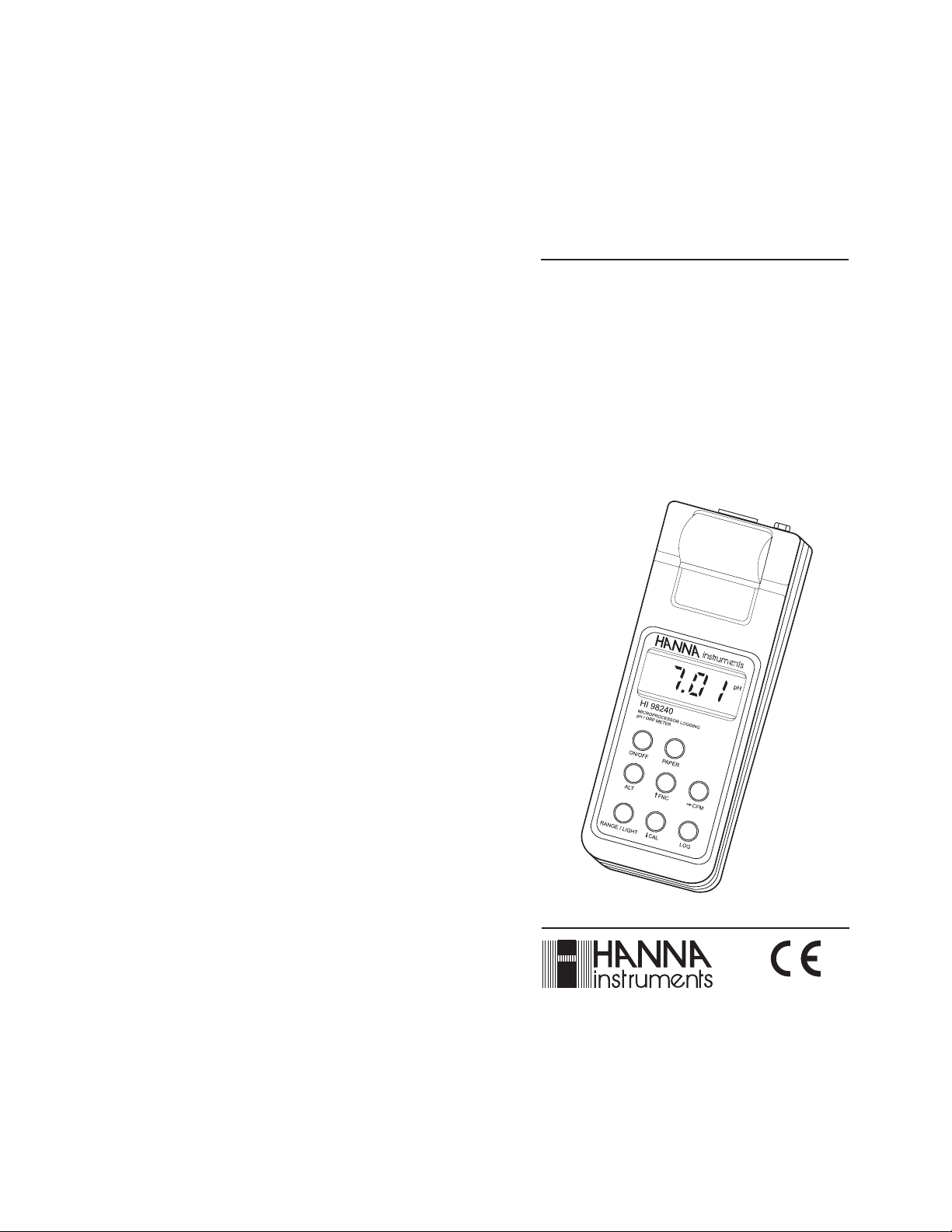
HI 98230 - HI 98240
Portable
Microprocessor
Printing and Logging
pH / ORP Meters
http://www.hannainst.com
These Instruments are in
Compliance with the CE Directives
Page 2
Dear Customer,
Thank you for choosing a Hanna Instruments Product.
Please read this instruction manual carefully before using the
instrument.
This manual will provide you with all the necessary information for
the correct use of the instrument, as well as a precise idea of its
versatility in a wide range of applications.
These instruments are in compliance with directives.
TABLE OF CONTENTSTABLE OF CONTENTS
TABLE OF CONTENTS
TABLE OF CONTENTSTABLE OF CONTENTS
PRELIMINARY EXAMINATION ................................................................. 3
GENERAL DESCRIPTION ....................................................................... 3
FUNCTIONAL DESCRIPTION ...................................................................5
SPECIFICATIONS .............................................................................6
INITIAL PREPARATION ..........................................................................7
SETUP MODE ............................................................................. 8
TAKING pH MEASUREMENTS ...............................................................15
TAKING ORP MEASUREMENTS ............................................................. 16
TAKING TEMPERATURE MEASUREMENTS .............................................. 16
pH CALIBRATION PROCEDURE ............................................................. 17
mV CALIBRATION PROCEDURE ........................................................... 20
TEMPERATURE CALIBRATION PROCEDURE ............................................ 21
PRINTING / LOGGING FUNCTION ......................................................... 22
OTHER FEATURES ........................................................................... 24
GOOD LABORATORY PRACTICE (GLP) ................................................... 25
FAULT CONDITIONS .......................................................................... 26
DATA TRANSFER TO PC ......................................................................27
MEMORY ORGANIZATION ................................................................... 28
PRINTER MAINTENANCE .................................................................... 29
BATTERY REPLACEMENT .................................................................... 30
TEMPERATURE-RESISTANCE CORRELATION
FOR HANNA PH SENSITIVE GLASS ........................................................ 31
ELECTRODE CONDITIONING AND MAINTENANCE ..................................... 32
ACCESSORIES .................................................................................. 35
OTHER PRODUCTS FROM HANNA ........................................................ 37
WARRANTY..................................................................................... 38
CE DECLARATION OF CONFORMITY ...................................................... 39
PRELIMINARY EXAMINATIONPRELIMINARY EXAMINATION
PRELIMINARY EXAMINATION
PRELIMINARY EXAMINATIONPRELIMINARY EXAMINATION
Remove the instrument from the packing material and examine it
carefully to make sure that no damage has occurred during shipping.
If there is any damage, notify your Dealer.
Each printing/logging pH meter is supplied complete with:
• Amplified pH electrode with built-in temperature sensor and
EEPROM for GLP data and DIN connector
• AA size Alkaline Batteries (4 pcs)
• HI70004 pH 4.01 sachet (1 pc)
• HI70007 pH 7.01 sachet (1 pc)
• Instruction Manual
• Paper rolls (5 pcs)
• Rugged Carrying Case.
Note: Save all packing material until you are sure that the
instrument functions correctly. All defective items must be
returned in their original packaging together with the supplied accessories.
GENERAL DESCRIPTIONGENERAL DESCRIPTION
GENERAL DESCRIPTION
GENERAL DESCRIPTIONGENERAL DESCRIPTION
HI98240 is a portable printing and logging microprocessor-based pH/
ORP/temperature meter.
HI98230 is a portable printing and logging microprocessor-based pH/
temperature meter.
HI98230 and HI98240 are supplied with an exclusive HANNA
(smart) amplified pH/temperature electrode with DIN connector. The
electrode has an internal memory for storing calibration data.
All pH measurements are automatically compensated for temperature
(ATC). The instrument housing is made of rugged, lightweight material,
making it truly portable.
Five memorized buffers (4.01, 6.86, 7.01, 9.18 and 10.01pH) and
wrong buffer recognition technology make calibration simple and error
free. One or two-point calibration is possible.
The meters are also equipped with a stability indicator and backlight
feature for comfortable reading even in excessively dark environments.
A user friendly interface provides clear messages regarding errors,
functions and more.
The GLP features provide a guarantee of data consistency.
Measurements can be performed with lab-grade precision in the field as
well as in the laboratory.
32
Page 3
An alarm time-out is available to alert the user if too much time has
elapsed since the last pH calibration and that re-calibration may be
required.
The meters provide a controlled access to calibration and GLP settings
through a password protection method.
The Battery Error Preventing System (BEPS) recognizes batteries levels
as they become weaker.
To prolong battery life, the backlight and printing features are
disabled when the batteries are getting low; "LOBAT" indication is
displayed on LCD to warn the user of this condition. However, the
meter continues to measure correctly even when the low battery
indication is displayed. The meter automatically switches itself off
when the batteries are too weak to support proper function.
The meters are equipped with an internal lithium battery that
powers the clock circuit even in the absence of power supplies.
For long term field and lab applications, these meters can be connected
to a 12VDC adapter.
When in logging mode, the meter stores the measurements in memory
at a user selectable interval from 1 to 180 minutes. This information can
be retrieved at a later time and also printed.
HI98230 and HI98240 also allow the transfer of stored data to a
computer via the HI9200 infrared transmitter connected to the
computer RS232 port.
In addition, the meters allow the user to enter an ID code to uniquely
identify the instruments.
FUNCTIONAL DESCRIPTIONFUNCTIONAL DESCRIPTION
FUNCTIONAL DESCRIPTION
FUNCTIONAL DESCRIPTIONFUNCTIONAL DESCRIPTION
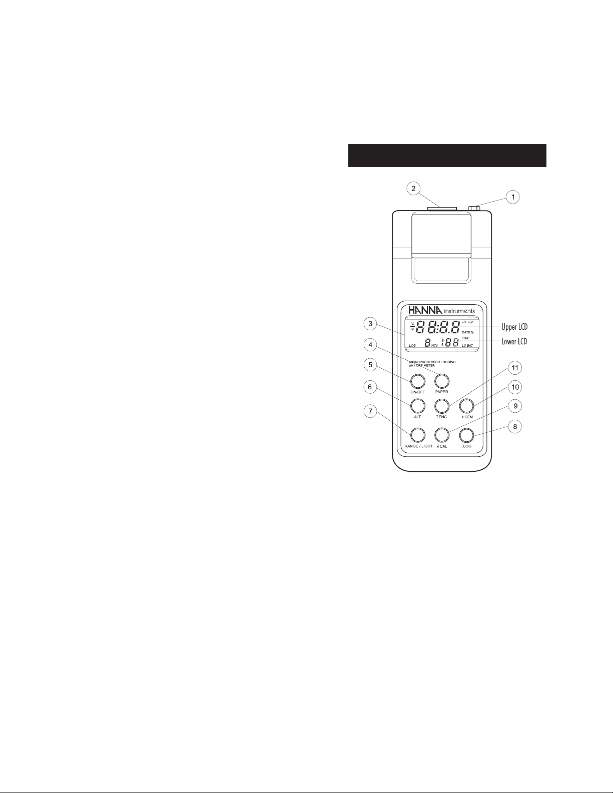
1) Power adapter plug
2) Electrode Connector
3) LCD Display
4) PAPER key, to move the paper up
5) ON/OFF key, to turn the meter on or off
6) ALT key, to alternate key function
7) RANGE/LIGHT key, to select measurement ranges, to display
time and to enable/disable backlight (with ALT)
8) LOG key, to store measurements
9) ÈCAL key, to move down or enter calibration (with ALT)
10) ÆCFM key, to move right or confirm values (with ALT)
11) ÇFNC key, to move up or select function codes (with ALT)
54
Page 4
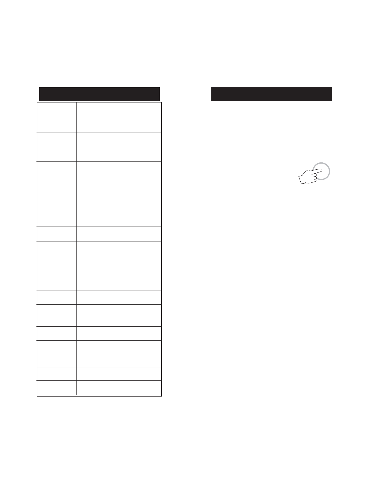
SPECIFICATIONSSPECIFICATIONS
SPECIFICATIONS
SPECIFICATIONSSPECIFICATIONS
INITIAL PREPARATIONINITIAL PREPARATION
INITIAL PREPARATION
INITIAL PREPARATIONINITIAL PREPARATION
Range pH -4.00 to 19.99 pH
mV ±400.0 mV (HI98240 only)
±2000 mV autoranging (HI98240 only)
Temp. -10.0 to 120.0 C (14.0 to 248.0 F)
Resolution pH 0.01 pH
mV 0.1 mV between ±400mV (HI98240 only)
1 mV outside (HI98240 only)
Temp. 0.1 C (0.1F)
Accuracy pH ±0.01 pH @25ºC
(@20C/68F) mV ±0.5mV between ±400mV (HI98240 only)
±2mV outside (HI98240 only)
Temp. ±0.5 C (1F) from 0 to 70C (32 to 158F)
±1C (1.8F) outside
Typical EMC pH ±0.03 pH
Deviation mV ±1mV between ±400mV (HI98240 only)
±2 mV outside (HI98240 only)
Temp. ±0.8C (1.4F)
pH Calibration Automatic, at 1 or 2 points with 5 memorized
buffers (4.01, 6.86, 7.01, 9.18 and 10.01 pH)
mV Calibration Automatic, 2 points at 0 and 350 mV or
(HI98240 only) 3 points at 0, 350 and 1900 mV
Temperature
Compensation Automatic from -10 to 120C (14 to 248F)
pH Electrode Amplified pH electrode with built-in tempera-
ture sensor and EEPROM for GLP data and
DIN connector (see accessories)
ORP Electrode Amplifed ORP electrode with DIN connector
(HI98240 only) (see accessories)
Input Impedance 10
Printer Low power impact type-belt, 14 characters
Printing/Logging 1, 2, 5,10, 15, 30, 60, 120 and 180 minutes
Interval
Power supply 4x1.5V AA alkaline type/350 hours typical life
Environment 0 to 50C (32 to 122F);
Dimensions 220 x 82 x 66 mm (8.7 x 3.2 x 2.6")
Weight 500 g (18 oz)
12
Ohm
per line; 38 mm plain paper (HI 710034)
(with 2700mA/h batteries, without printing
and backlight).
12 VDC adapter (HI710005 or HI710006)
0-95% RH non-condensing
Each meter is supplied complete with batteries. Remove the back
cover, unwrap the batteries and install them while paying attention
to the polarity. Alternatively, connect the HI 710005 or HI 710006
voltage adapter to the power adapter plug.
To prepare the instrument for use, connect the pH or ORP (HI98240
only) electrode to the connector located on the top of the instrument.
To switch the meter on, press the ON/OFF key.
The batteries charge status or "LINE" message
(if external power adapter is connected) will be
displayed on the LCD for a few seconds.
The meter is now ready to operate.
To maximize battery life, the meter is automatically switched off after a
user selectable period of non-use (default is 5 minutes). If in logging
mode, after the period of non-use, the meter will continue to monitor
pH or mV (HI98240 only) and temperature periodically at the end of
every logging interval. Only the "LOG" indication will be visible on
LCD. While storing data in memory, during the sleep mode, the
reading will appear briefly on the LCD.
Before proceeding with pH measurements follow the calibration procedure.
Note: When the use of an alternate function (FNC, CFM and CAL) is
requested, press and hold the ALT key first and then the
second listed key.
Note: To prevent damage to the electrode, remove the pH electrode
from the sample before turning the meter off.
If the meter is OFF, detach the electrode from the meter before
immersing the electrode in the storage solution.
ON/OFF
76
Page 5
SETUP MODESETUP MODE
SETUP MODE
SETUP MODESETUP MODE
Setup can be used to view data regarding instrument status (e.g.
battery charge) or GLP data (e.g. calibration date) or to view or print
the logged data. It also allows the user to change the meter
parameters (e.g. time) and to have access to stored data.
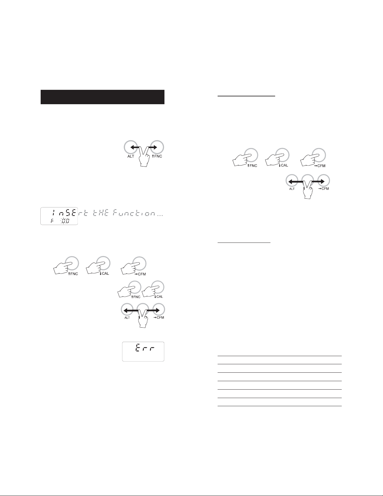
• To enter this mode ensure the meter is
not logging and then press the ALT and
FNC keys.
PASSWORD PROTECTION
Setting of the GLP parameters (calibration alarm time-out, instrument ID code, time and date) can be password protected. If password
is set to a value different from 0000 (factory setting), the user will be
asked to enter the password.
• Select the desired GLP parameter code.
• Enter the password by the arrow keys.
• The scrolling message "Insert the function code or press ALT - FNC
to escape" in the upper LCD and the indication "F 00" with the
first digit blinking in the lower LCD will be displayed.
• Enter the first digit of the code of the parameter you want to set
using the Ç or È key and pass to the next digit with Æ. The
second digit will start blinking.
• Enter the second digit using the Ç or
È key.
• Press ALT and CFM to confirm the code.
• If the entered code doesn't exist the "Err"
message will be displayed for a few
seconds and then the message "Insert
the function code or press ALT - FNC to
escape" will recommence scrolling in the
upper LCD.
• Press the ALT and CFM keys to
confirm.
• If password is wrong the meter will return to the function selection
mode without any warning message.
• If password is correct, the meter provides access to the parameter.
PARAMETER SETTINGS
• Once the parameter code has been entered, the appropriate
message will scroll across the LCD for a few seconds.
• The current value of the selected parameter on the upper LCD
and the parameter code on the lower LCD will be displayed. The
first digit will blink if the parameter can assume continuous
values. All the digits will blink if the parameter can assume only
a fixed set of values.
• Enter the new value using the arrow keys.
• Press ALT and CFM to confirm the value.
The following table lists the setup codes along with the description of
the specific setup items, their valid values and the factory settings
(default):
Code Valid values Default
00 Lot data printing/scrolling 0016 00
01 Print lots data summary
02 Printer enable On(enabled); Off(disabled) On
03 Logging interval 1,2,5,10,15,30,60,120,180 1
05 Log on demand delete
06 Timed data delete
98
Page 6
Code Valid values Default
10 Show pH GLP data
11 Show ORP GLP data (HI98240 only)
12 Print GLP data
13 Calibration alarm time-out 0099 days 00
00 means option disabled
14 Instrument ID code 00009999 0000
30 Current time
31 Current day
32 Current month
33 Current year
1
1
1
1
hh:mm 00:00
dd 01
MM 01
YYYY 1998
40 Auto-Off/Power down time-out 5,10,15,30,45,60 5
41 Battery level test
50 RS232 baud rate 1200, 2400, 4800 4800
60 Firmware version
70 Celsius/Fahrenheit selection C ; F C
99 Password
2
00009999 0000
Note: If a wrong code is entered the "Err" message is displayed on
LCD for a few seconds.
1
The meter automatically checks for entered time/date accuracy as follows:
0≤hh≤23; 0≤mm≤59; 01≤dd≤28/29/30/31; 1≤MM ≤12; 1998≤YYYY≤2097.
2
To change the password, the correct code must be entered first. If the password
has been forgotten, the password protected features are no longer accessible;
in this case contact your nearest Hanna Service Center.
SETUP MESSAGES LIST
cod. 00: Lot data Printing
cod. 01: Lot table Printing
cod. 02: Printer enable
cod. 03: Log Interval
cod. 05: Press "ALT CFM" to delete Lot 00 or "ALT FNC" to escape
cod. 06: Press "ALT CFM" to delete Lot 01-16 or "ALT FNC" to escape
cod. 10: pH GLP
cod. 11: Volt GLP (HI98240 only)
cod. 12: GLP data printing
cod. 13: Calibration alarm time-out
cod. 14: Instrument ID Code
cod. 30: Hour - Minute
cod. 31: Day
cod. 32: Month
cod. 33: Year
cod. 40: Auto OFF
cod. 41: Battery test
cod. 50: Baud rate
cod. 60: Release code
cod. 70: Celsius or Fahrenheit
cod. 99: Pass Code
Some of the most important functions are explained below in a step
by step sequence.
TO SCAN LOGGED DATA
COD. 00 - Lot data Printing / Scrolling
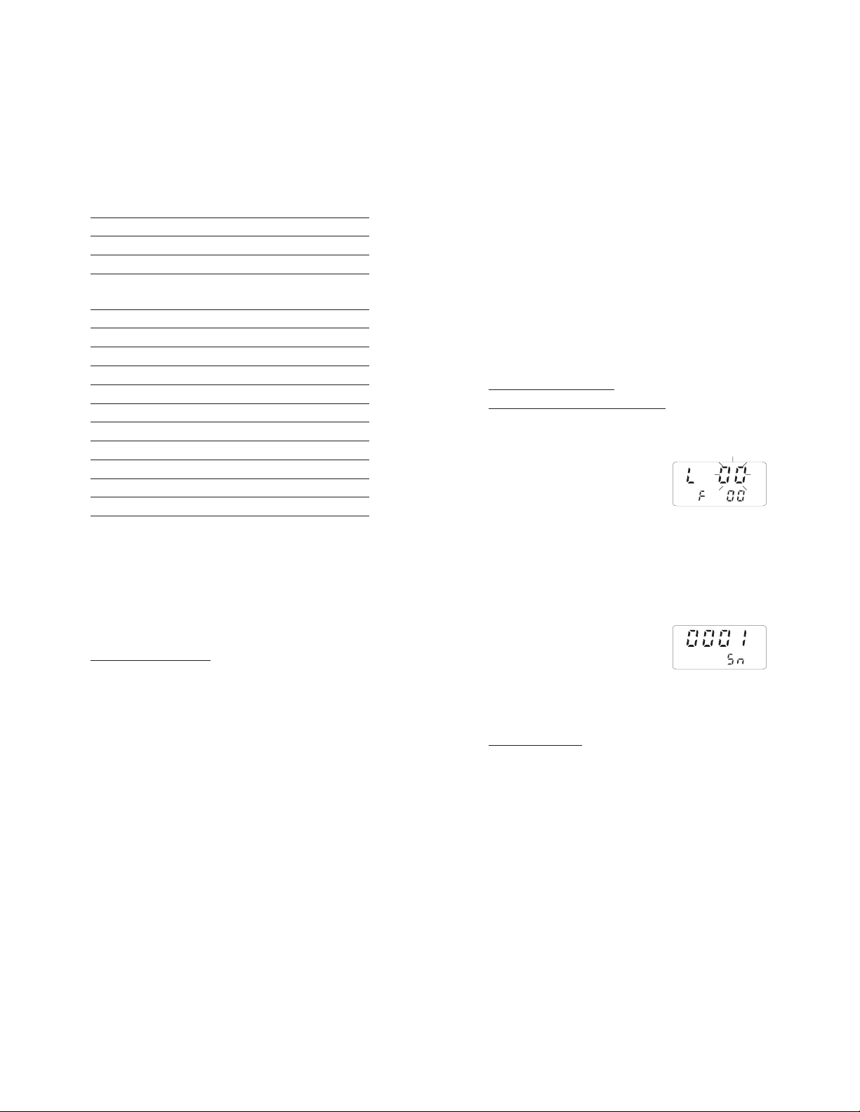
• Select the code 00.
• The message "Lot data Printing" will scroll twice on LCD.
• The upper LCD will then display L 00
with the 00 blinking.
• Set the desired lot by the arrow keys. L00 is the lot of data of the
"log on demand" and L01 to L16 are the lots of the "timed log".
• Press the ALT and CFM keys to confirm the lot number.
• If the lot doesn't contain data, the "no data" message will scroll
across the LCD twice and the meter will return to setup mode.
• If the lot contains one or more data the
LCD will display the sample number in its
upper part and Sn in the lower part.
Note: In the L00 lot (log on demand) the sample number will be
displayed with 3 digits (001).
• Select the sample number to scan by the arrow keys.
Printing logged data
• Press ALT and CFM to print logged data.
• If the selected sample number is invalid (equal to 0 or bigger
than the number of samples), the "Err" message will be displayed
for a few seconds.
• If the sample number is correct, the samples starting from the
selected one to the last sample of the lot will be printed. To stop
printing before the last sample is reached, press and hold the ALT
and PAPER keys until the printer stops.
• During printout the LCD will display the sample number being
1110
Page 7
printed at that moment. If printout is stopped the LCD will show
the last printed sample number. It is then possible to select
another sample.
• Press the ALT and FNC keys to return to setup mode.
Viewing logged data
• Press RANGE to view data of the selected sample. Data will be
displayed in the following order:
pH or mV (mV reading available in HI98240 only)
temperature
date
time
• If RANGE is pressed when the time is displayed, the LCD will pass
to the next Sample number.
• It is then possible to scroll the data of the next sample by
pressing RANGE or select a different sample by the arrow keys.
• to return to setup mode, press ALT and FNC when the meter
displays the sample number.
Cod. 01 - Lot summary printout
• Select the code 01.
• The message "Lot table Printing" will scroll twice on LCD.
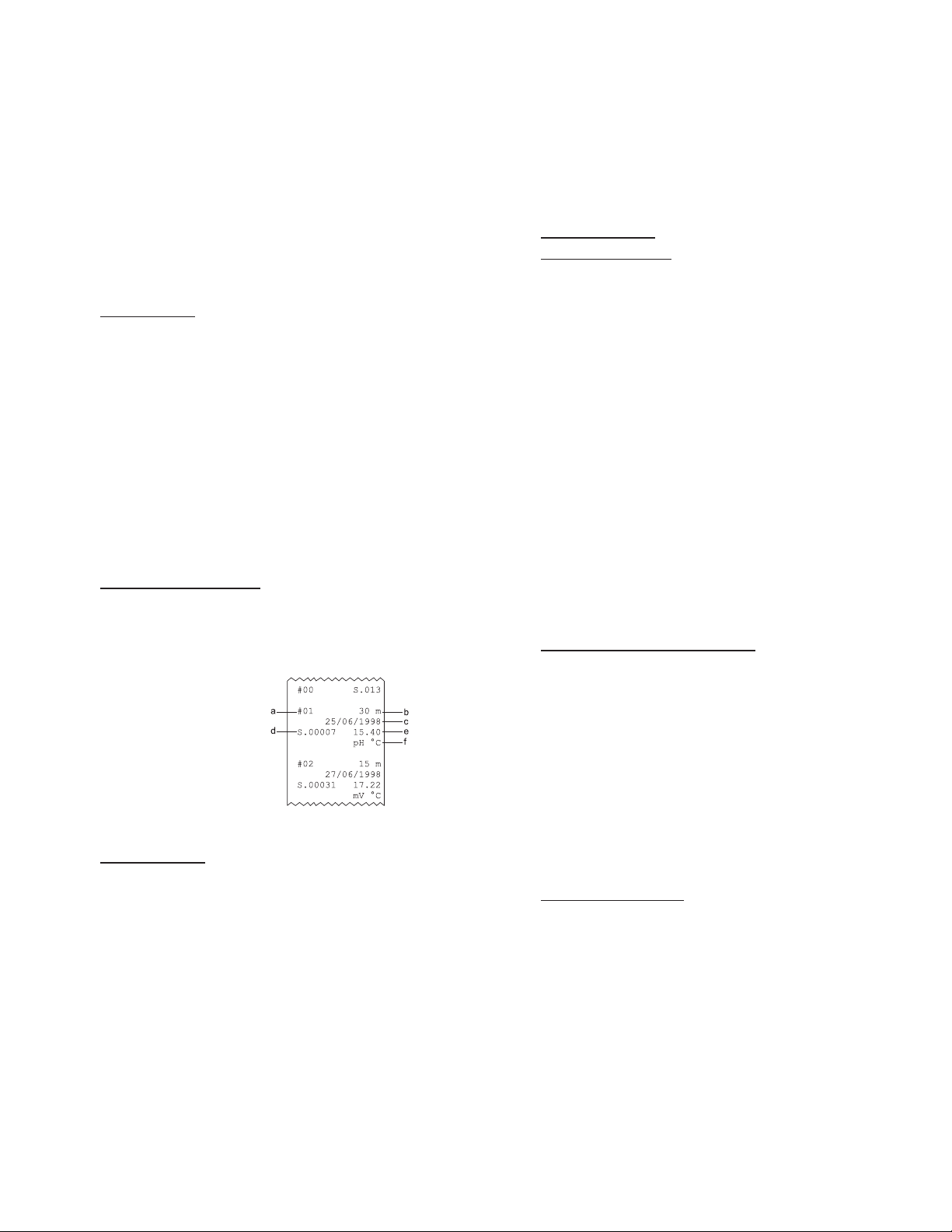
• The meter will then print a complete set of information based on
the data stored in memory:
a - lot number
b - logging interval
c - starting date
d - number of samples
e - starting time
f - number and measure unit of
the logged channels.
Note: For lot 00 the number of samples only will be printed.
DELETE SET DATA
• Select code 05 to delete the Log on Demand data or code 06 to
delete the Timed Log Data.
• A scrolling message will be displayed.
• Press the ALT and CFM keys to confirm deletion.
• It is also possible to escape without data deletion pressing the ALT
and FNC keys.
TO SCAN GLP DATA
Cod. 10 - viewing pH GLP
• Select the code 10
• The " pH GLP" message will scroll twice on LCD.
• Electrode calibration data are verified to be within acceptable
values. If not the message "Old probe" or "Dead probe" will scroll
once on LCD, depending on calibration data.
• The LCD will then display the instrument identification (ID) code.
• Press Ç to scan remaining data, in the following order:
last calibration date (DD.MM)
last calibration year
last calibration time (hh.mm)
electrode offset value in mV ("OF" appears in the lower LCD)
electrode slope in mV/pH ("SL" appears in the lower LCD)
first point calibration buffer
second point calibration buffer (only if a 2-point calibration has
been performed).
Note: Data can be viewed in reverse order pressing the È key.
• Press ALT and FNC to return to function selection mode.
Code 11 - Viewing mV GLP (HI98240 only)
• Select code 11. The message "Volt GLP" will scroll twice across LCD.
• The LCD will then display the instrument identification (ID) code.
• Press Ç to scan remaining data, in the following order:
last calibration date (DD.MM)
last calibration year
last calibration time (hh.mm)
first calibration point
second calibration point
third calibration point (if present).
• Press ALT and FNC to return to setup mode.
Code 12 - printing GLP data
• Select code 12. The message "GLP data printing" will scroll across
LCD.
• The meter will then print a complete set of the following GLP
data:
a - Instrument identification (ID) code
1312
Page 8

b - last pH calibration date
c - last pH calibration time
d - pH electrode offset
e - pH electrode slope
f- 1st point pH calibration buffer
g- 2nd point pH calibration buffer
(if present)
h - last mV calibration date
(HI98240 only)
i - last mV calibration time
(HI98240 only)
l- 1st point mV calibration (HI98240 only)
m- 2nd point mV calibration (HI98240 only)
n- 3rd point mV calibration (if present; HI98240 only).
Note: If the pH is followed by a set of * or -, it means that the
pH electrode is old or dead respectively.
A dashed line indicates that the calibration has never been
performed.
If the calibration date is followed by the symbol "Dt", it means
that the calibration alarm time-out period has been exceeded.
Code 13 - setting the identification (ID) code
When using several identical meters it may be useful to uniquely
identify them by assigning an ID code to each meter.
• Select code 13. The message "Instrument ID code" will scroll across
LCD.
• Enter a 4-digit value using the arrow keys.
• Press ALT and CFM to confirm the value.
TESTING BATTERY LEVEL
• Select code 41. The message "Battery test" will scroll across LCD.
• If the meter is connected to an external power adapter, the LCD
will display "LINE", otherwise it will display bAtt on the upper
display, and the remaining percentage
of battery charge (100% means fully
charged battery and 0% corresponds to
the minimum battery voltage that allows the meter to operate).
TAKING TAKING
TAKING
TAKING TAKING
Connect the pH electrode with the built-in
temperature sensor to the meter and press
ON/OFF to power on the instrument.
The meter automatically checks that the stored calibration data
correspond to the connected electrode. The pH range will be automatically set.
If the pH electrode is not connected, the LCD will display the "no
probe" message and then dashed lines in place of the readings.
For greatest accuracy, it is recommended to set
the Calibration alarm time-out to the value
appropriate to your specific use and calibrate
the meter as soon as the "DATE" warning
symbol blinks on LCD (see page 25).
To take pH measurements, simply submerge
the bottom 4 cm (1½") of the electrode in
the solution to be tested, stir gently and
allow for the reading to stabilize. The temperature is displayed in the lower LCD without
the decimal digit.
The pH reading is automatically temperature compensated (ATC).
If the pH reading blinks it means that the electrode is "dead" and
readings are not reliable.
By continuously pressing the RANGE key the follow-
ing information will be displayed on the upper LCD:
• mV reading (HI98240 only)
The mV scale is autoranging, when the
reading is outside ±400mV the decimal
point automatically disappears.
• Temperature reading
If the temperature reading is out of
range, a dashed line will be displayed.
• Date
• Time
Pressing RANGE again, the meter returns to pH reading.
If measurements are taken successively in different samples, it is
recommended to rinse the electrode thoroughly with deionized water
or, if not available, tap water first and then with some of the next
sample to condition the electrode before immersing it in the sample.
pp
H MEASUREMENTSH MEASUREMENTS
p
H MEASUREMENTS
pp
H MEASUREMENTSH MEASUREMENTS
1514
Page 9

TAKING ORP MEASUREMENTSTAKING ORP MEASUREMENTS
TAKING ORP MEASUREMENTS
TAKING ORP MEASUREMENTSTAKING ORP MEASUREMENTS
(HI98240 ONLY)(HI98240 ONLY)
(HI98240 ONLY)
(HI98240 ONLY)(HI98240 ONLY)
Connect the ORP electrode to the meter and
press ON/OFF to power on the instrument.
The meter automatically sets the mV range.
If the ORP electrode is not connected, the LCD will display the "no
probe" message and then dashed lines in place of the readings.
To take ORP measurements, simply submerge the bottom 4 cm (1½")
of the ORP electrode in the solution to be tested, stir gently and allow
for the reading to stabilize.
The lower LCD displays the temperature reading, or a dashed line if
the ORP electrode is not provided with the temperature sensor.
By continuously pressing the RANGE key the following information will
be displayed on the upper LCD:
• Temperature reading
If the ORP electrode is not provided with the temperature sensor,
a dashed line will be displayed.
• Date
• Time
Pressing RANGE again, the meter returns to mV reading.
If measurements are taken successively in different samples, it is
recommended to rinse the electrode thoroughly with deionized water
or, if not available, tap water first and then with some of the next
sample to condition the electrode before immersing it in the sample.
pp
H CALIBRATION PROCEDUREH CALIBRATION PROCEDURE
p
H CALIBRATION PROCEDURE
pp
H CALIBRATION PROCEDUREH CALIBRATION PROCEDURE
For better accuracy, it is recommended to calibrate the instrument
frequently. For a faster procedure, it is possible to calibrate at 1
point, but it is always a good practice to calibrate at 2 points.
A two-point calibration can use any combination of the three sets:
(4.01) (6.86 / 7.01) (9.18 / 10.01)
Only one value from each set can be selected. For example if pH
7.01 is used as first point, it will not be possible to select pH 6.86
as the second point.
In the case of a two-point calibration, in the acidic range (from 0 to
7 pH) use pH buffer 7.01 (or 6.86) as the first solution and pH buffer
4.01 as the second solution. If testing in the alkaline range (from 7
to 14 pH), use pH buffer 10.01 (or 9.18) as the second solution.
Due to electrode conditioning time, the electrode must be kept
immersed a few seconds to stabilize. The meters are equipped with a
stability indicator (a blinking "S") and the user will be guided step by
step with easy indications on the LCD during the calibration. This will
make the calibration a simple and error-free procedure.
pH CALIBRATION
1. Rinse the electrode with a portion of the first
calibration buffer or clean water. Dip the
bottom, 4 cm (1½"), of the electrode into a
beaker containing the solution.
2. Press ALT and CAL while meter is not printing nor logging.
TAKING TEMPERATURE MEASUREMENTSTAKING TEMPERATURE MEASUREMENTS
TAKING TEMPERATURE MEASUREMENTS
TAKING TEMPERATURE MEASUREMENTSTAKING TEMPERATURE MEASUREMENTS
The temperature sensor is integrated in the pH electrode.
Secure the connection of the electrode to the top of the meter and
immerse it in the sample solution (allow a few minutes for the
temperature to stabilize). Press ON/OFF to power on the instrument.
The temperature is displayed in the lower LCD without the decimal
digit during pH and mV measurement. To display the temperature
reading with decimal digit, press the "RANGE" key to get into the C
or F mode. The temperature value and the "C" or "F" symbol will
be displayed on the upper display.
Note: To choose between "C " and "F" unit, enter the setup code 70.
Note: If temperature measurement is out of range the LCD will
display "- - - -".
3. User is prompted to enter password if it has been set to a value
different from 0000, otherwise skip to step 6.
4. Enter the password with the arrow keys.
5. Press ALT and CFM to confirm the password or ALT and CAL to
exit.
1716
Page 10
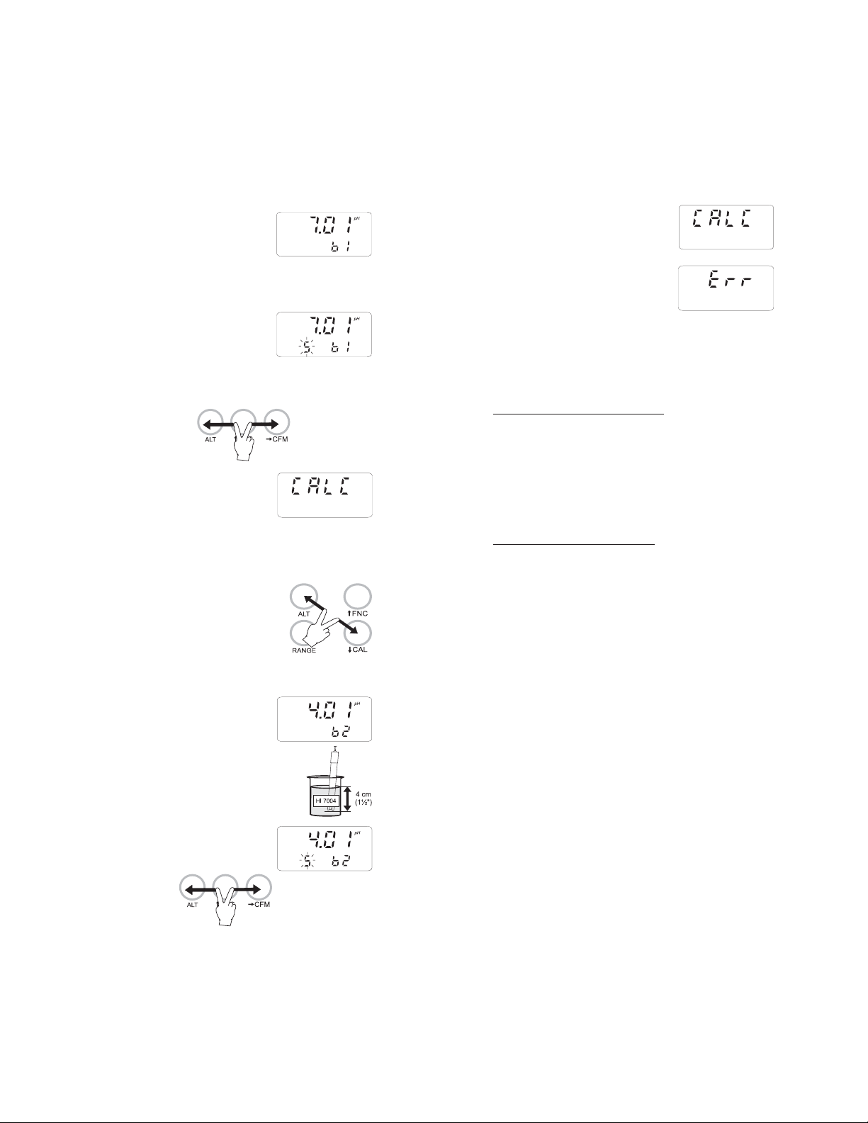
6. If password is correct or not set, the
meter will display "7.01pH" on the upper LCD and "b1" on its lower part; if
wrong, it will return to measurement
mode without any message.
7. Select the first buffer solution value with Ç and È if necessary.
8. When the "S" symbol blinks in the lower
LCD, the reading is stable and calibration can be confirmed.
Note: It is possible to display temperature pressing the RANGE key.
9. Press ALT and CFM to confirm the first buffer.
10.If everything is satisfactory the LCD will
display CALC and then the second buffer
value expected will be displayed. If a
wrong solution or electrode has been used or if the buffer is
polluted, "WRONG" will be displayed to alert the user.
11.If only a single point calibration is required, press ALT and CAL to leave the
calibration mode and maintain the previous slope calibration. "CALC" will be displayed
for a few seconds. The instrument then
checks the electrode parameters and advises user of abnormalities by "old probe"
and "dead probe" indications.
12. Press Ç or È to select the second
buffer value. The "b2" symbol will be
fixed on lower display.
13.Rinse the electrode with some of the second
buffer solution or clean water.
14.Dip the bottom, 4 cm (1½"), of the electrode
in a beaker containing the second buffer.
15.When the "S" symbol blinks in the lower
LCD, press ALT and CFM to confirm the
second calibration point.
16."CALC" is displayed on the upper LCD for
a few seconds and the meter is calibrated and ready to use.
17.If the buffer is wrong or the electrode is
defective, "Err" will be displayed to alert
the user. When calibration is completed,
the instrument checks the electrode parameters and advises the user of abnormalities by "old probe"
and "dead probe" indications (in these cases, repeat the calibration with fresh buffers).
CALIBRATION ERROR MESSAGES
If the "old probe", "dead probe" or "Err" messages are displayed
during calibration, check your electrode by following the conditioning
and maintenance procedure and repeat calibration. The pH electrode
might have to be replaced if calibration cannot be successfully
performed.
CALIBRATION DATA PRINTOUT
It is possible to print the characteristics of the electrode as a recording
of the electrode performance over time by setup code 12 (see "Printing
GLP data").
This will consist of: date, time, the offset characteristic of the pH
electrode in mV, the slope characteristic in mV/pH and the pH buffer
solution values.
If calibration has been performed with an "old" pH electrode the first
line is: pH **
If calibration has been performed with a "dead" pH electrode the first
line is: pH
If the calibration alarm time-out is expired, the "Dt" string will be
printed beside the date.
Note: A dashed line indicates that the calibration has never been
--
performed.
1918
Page 11

mV mV
CALIBRATION PROCEDURECALIBRATION PROCEDURE
mV
CALIBRATION PROCEDURE
mV mV
CALIBRATION PROCEDURECALIBRATION PROCEDURE
(HI98240 ONLY)(HI98240 ONLY)
(HI98240 ONLY)
(HI98240 ONLY)(HI98240 ONLY)
A four-point calibration must be performed. The first two calibration
points are 0.0 and +350.0 mV for low range calibration; the other
two calibration points are 0 and +350 or +1900 mV for high
range calibration.
1. Connect a mV simulator (HI8427 or HI931001 with the proper
connecting cable) to the meter and set it to 0 mV.
2. Press ALT and CAL when LCD is displaying mV.
3. User is prompted to enter password if it has been set to a value
different from 0000, otherwise skip to step 6.
4. Enter the password with the arrow keys.
5. Press ALT and CFM to confirm the password or ALT and CAL to
return to normal operational mode.
6. If password is correct or not set, the
meter will display "0.0 mV" on the upper LCD and "b1" on the lower; if wrong,
it will return to normal operational mode without any message.
7. When the "S" symbol blinks in the lower
LCD, the reading is stable and calibration can be confirmed.
8. Press ALT and CFM to confirm the first value.
9. The meter will display "350.0 mV" in the
upper LCD and "b2" on the lower one.
10.Set the simulator to +350 mV.
11.When the "S" symbol blinks in the lower
LCD, the reading is stable. Press ALT and
CFM to confirm the second value.
12.The meter will display "0 mV" in the
upper LCD and "b3" on the lower one.
13.Set the simulator to 0 mV.
14.When the "S" symbol blinks in the lower
LCD, the reading is stable. Press ALT and
CFM to confirm the third value.
15.The meter will display "350 mV" in the
upper LCD and "b4" on the lower one.
Pressing the "Ç" key, 1900 mV will be
selected as calibration point.
Note: +1900 mV is suggested as the last calibration point to
obtain the best accuracy throughout the entire mV range.
16.Set the simulator to +1900 mV.
17.When the "S" symbol blinks in the lower
LCD, the reading is stable. Press ALT
and CFM to confirm the fourth value.
18.Calibration is now complete and the instrument returns to normal
operational mode.
Note: "Err" message notifies the user if the selected value is wrong.
TEMPERATURE CALIBRATION PROCEDURETEMPERATURE CALIBRATION PROCEDURE
TEMPERATURE CALIBRATION PROCEDURE
TEMPERATURE CALIBRATION PROCEDURETEMPERATURE CALIBRATION PROCEDURE
((
for technical personnel only)for technical personnel only)
(
for technical personnel only)
((
for technical personnel only)for technical personnel only)
The meter is factory calibrated for temperature. It is recommended
that the following procedure is performed by authorized technical
personnel only.
A two point calibration at 0.0, 25.0C (32.0, 77.0F) or 0.0, 50.0C
(32.0, 122.0F) has to be performed in order to store the new
calibration data in memory.
1. Immerse the electrode with the built-in temperature sensor in the
0C (32F) temperature bath.
2. Press RANGE until temperature reading is selected.
3. Press ALT and CAL to enter temperature calibration mode.
4. Enter the password if requested.
5. When the reading is stable the "S" symbol starts to blink.
6. Press ALT and CFM to confirm. LCD will display 50.0C (122.0F)
as the following calibration point.
7. If 25.0C (77.0F) is desired as second point, press È to display
25.0C (77.0F).
8. Immerse the probe in the second temperature bath.
9. When the reading is stable, the "S" symbol starts to blink.
10.Press ALT and CFM to confirm and return to temperature reading
mode.
2120
Page 12
PRINTING / LOGGING FUNCTIONPRINTING / LOGGING FUNCTION
PRINTING / LOGGING FUNCTION
PRINTING / LOGGING FUNCTIONPRINTING / LOGGING FUNCTION
Two different modes to print / log data are available:
1. Timed logging; samples are stored and printed (if print function is
active) at fixed time intervals. Data are stored in the lots 01 to 16.
2. Log on demand; samples are stored and printed (if print
function is active) when the LOG key is pressed. Data are stored
in the lot 00. It's possible to perform the Log on demand either
in normal mode or in Timed logging mode.
It is possible to switch from logging without printing to logging with
printing in two ways:
• set the function code 02 to "On" to enable printing, to "Off" to
disable printing
• press ALT and PAPER to toggle between printer enabled and
printer disabled while in Timed logging.
TIMED LOGGING MODE
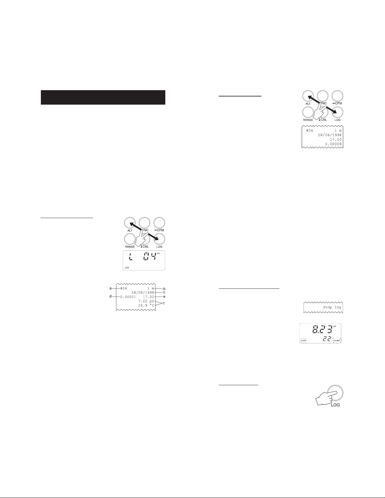
To start Timed logging, press ALT and LOG.
The lot number will be displayed for a few
seconds then the LOG symbol will appear on
LCD and if printer is enabled a first set of
data will be printed. The "LOG" symbol will
be fixed if printer is enabled and will blink if
printer is disabled.
The printout provides the following information:
a - Lot number
b - Logging interval
c - Date (only for the first printed
sample of the lot or of the day)
d - Sample number
e - Time
f - Readings.
To print the mV reading instead of pH, press ALT and LOG after
entering the mV range (mV reading available in HI98240 only).
If no keys are pressed, the meter enters standby mode to prolong the
battery life and only the "LOG" indication will be visible on LCD. While
logging, during the sleep mode, the last logged reading will appear
briefly on the LCD. To reactivate the LCD press ON/OFF.
TO STOP LOGGING
In order to stop the recording mode, press
ALT and LOG keys (press ON/OFF first, if
meter is in sleep mode).
A last printout reporting the number of
logged samples (e.g. S.00009) will be produced if printer is enabled.
Notes:
• It is recommended to use the adapter during logging in printing
mode, especially when many printouts are going to be taken.
• Before proceeding with logging with printing, make sure there is
enough paper for your measurements. When the paper is finished
the meter will not advise the operator and the printouts could be
lost. If this happens, data will continue to be stored in memory,
and it is always possible to print the data at a later time
through setup code 00.
• It is possible to insert a new paper roll during logging session (see
page 29)
• Once in the logging mode, the interval cannot be changed. Exit
the logging mode first (pressing the ALT and LOG keys) to set a
new interval.
• If the LOG key is pressed while in logging with printing mode, a
printout is produced without affecting the running sample number and the value is stored in Log on demand area.
LOW BATTERY CONDITION
Printout is automatically disabled when battery charge weakens. The
last message "Stop log" will be printed and
data will continue to be stored in memory
with the LOG and LOBAT symbols blinking
on LCD. If the user attempts to enable the
printer while in low battery condition the
message "bAtt" will appear for a few seconds on the LCD.
Note: When an external adapter or new batteries are connected, the
printing must be manually enabled in order to return to
logging with printing mode.
LOG ON DEMAND
In measuring or Timed log mode, press LOG to
store the current reading. The LCD will display
2322
Page 13
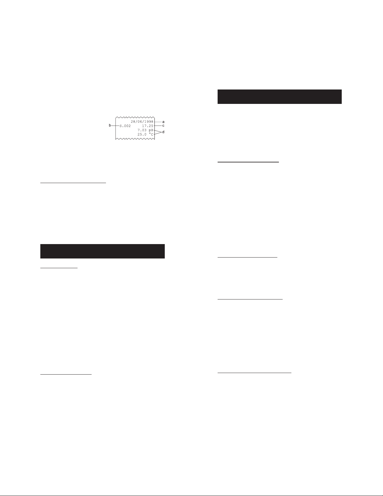
"Stor log" and the value will be stored in the lot 00 (log on demand
data area). If the printing function is enabled, a printout is also
produced providing the following information:
a - Date
b - Sample number
c - Time
d - Readings
Note: When the Log on demand data area is full and the LOG key
is pressed, the sample will not be stored and the LCD will
display "FULL". In this case it is necessary to delete the Log on
demand data to proceed.
TO RETRIEVE LOGGED DATA
Logged data stored in the EEPROM can be viewed on LCD or printed.
HI98230 and HI98240 also allow the downloading of logged data to
PC for reproduction, storage and elaboration (e.g. graph drawing).
To view or print logged data see "TO SCAN LOGGED DATA" on page 11.
To download data to PC see "DATA TRANSFER TO PC" on page 27.
OTHER FEATURESOTHER FEATURES
OTHER FEATURES
OTHER FEATURESOTHER FEATURES
LCD BACKLIGHT
The LCD can be illuminated to allow the user to see the readings even
in dark environments. This feature can be enabled/disabled pressing
the ALT and LIGHT keys.
If the LCD backlight feature is enabled, the LCD remains illuminated
until the feature is disabled pressing the ALT and LIGHT keys. The
LCD backlight can be disabled in order to save power and it is
automatically disabled when batteries are in low battery condition.
Note: When an external power supply is connected to the instru-
ment, the backlight is not automatically enabled.
Note: When LOBAT appears on LCD it is not possible to enable
backlight. If the user attempts to enable the LCD backlight in
low battery condition, the meter will show "bAtt" on LCD.
Real Time Clock (RTC)
The instrument has an internal Real Time Clock (RTC) circuit with a
backup lithium battery. This allows the meter to update time and
date even when both batteries and external power adapter are
disconnected.
GOOD LABORATORY PRACTICE (GLP)GOOD LABORATORY PRACTICE (GLP)
GOOD LABORATORY PRACTICE (GLP)
GOOD LABORATORY PRACTICE (GLP)GOOD LABORATORY PRACTICE (GLP)
GLP is a set of functions that allows the storage or retrieval (when
necessary) of data regarding the maintenance and status of the
electrode. The pH electrodes have a built-in EEPROM in which
calibration data are read at start-up and stored after calibration.
HI98230 and HI98240 can automatically analyze the data and
advise the user if a problem is found with a clear message.
PROBE LIFE VERIFICATION
At the end of calibration, the meter checks if offset is between -30 and
+30mV and the slope between 53.5 and 62 mV/pH. If the values are
not within these parameters, the message "old probe" scrolls across the
LCD and the symbol ** is reported in the Last Calibration Data. The
electrode is still working, but it will be necessary to perform a cleaning
procedure (see electrode cleaning and maintenance paragraph) or
replace it.
If the offset is outside the -60 and +60 mV range, the "dead probe"
message will scroll across the LCD and the symbol -- is reported in
the Last Calibration Data. The readings will blink to warn the user
that they are not reliable.
LAST CALIBRATION DATA
Last calibration data are stored automatically after a successful
calibration. Data can be displayed or printed through the appropriate setup codes (10 to display pH data; 11 to display mV data; 12
to print pH and mV data); mV data are available in HI98240 only.
ELECTRODE IDENTIFICATION
At start-up the meter checks if the electrode is inserted. If not the
message "no probe" scrolls across the LCD and a dashed line will be
display in place of the reading. Each printout will have a "◊" symbol
on the pH line.
If the meter detects a "dead probe" the reading will blink.
The meter checks the electrode only at start up. If an electrode
replacement is needed, turn the meter off before disconnecting the
electrode. Then replace the electrode and turn the meter on again.
CALIBRATION ALARM TIME-OUT
The calibration alarm time-out is available only for pH calibration.
It is possible to set (through setup code 13) the number of days
before the next required calibration procedure. User can set a value
from 00 (disabled) to 99 days. The default value is 00.
2524
Page 14

The meter checks if the time-out time has
expired every time it is turned on. In the
case the time has run out, the message "Cal
date" scrolls across the LCD. The "DATE" symbol will blink as a reminder.
Alarm time-out is also signaled in the GLP
data printout through the "Dt" symbol after
the calibration date.
GLP AND RS232
All the GLP data can be retrieved from a PC through the RS232
communication feature. The calibration data are transferred to the
computer along with measurement data for analysis and verification
(see "Data transfer to PC" paragraph).
FAULT CONDITIONSFAULT CONDITIONS
FAULT CONDITIONS
FAULT CONDITIONSFAULT CONDITIONS
HI 98230 and HI 98240 are factory programmed to automatically
diagnose a fault and to display error codes on the LCD.
PRINTER ERROR
Whenever a printer fault condition is detected, the printer stops and
the message "Printer error" scrolls across the upper LCD with the error
code (see below) fixed on the secondary one.
1 = Motor locked
2 = Printer clutch jammed
3 = Selection lever fault
I2C BUS ERROR
In case of an I2C bus fatal error due for example to a defective
EEPROM or RTC, the message "Serial bus error" keeps scrolling across
LCD from right to left indefinitely. Meter should be returned for repair
(see warranty section).
DATA TRANSFER TO PCDATA TRANSFER TO PC
DATA TRANSFER TO PC
DATA TRANSFER TO PCDATA TRANSFER TO PC
HI98230 and HI98240 contain infrared transmitting circuitry.
Ensure there is not any logging process active.
Press RANGE to set the meter to time or date mode and simply place
your data-logger on a HI9200 Infrared Transmitter (ensuring that
the two infrared LEDs are placed on top of each other) and the
memory content can then be downloaded to your PC through the
HI9200's RS232 port. Just ensure that baud rate on instrument
(setup code 50) and on PC downloading program are set to the same
value.
During the data transfer the instrument
displays the message "r 232".
To stop communication, press RANGE to display the reading (pH or
mV or temperature) or take the meter out of the transmitter when it
is not displaying "r232".
Using the HI9200 Infrared Transmitter, all recorded data can be fed
to your Personal Computer for easy reproduction, storage or elaboration without the interference of cables or cords between the meter and
the transmitter.
Data transmission from the instrument to the PC is now much easier
with new HI92000 Windows® compatible application software offered
by Hanna Instruments.
HI92000 allows to use the powerful capabilities of most spread sheet
programs (e.g. Excel©, Lotus 1-2-3©). Simply open the file downloaded by HI92000 from the spread sheet program and then it is
possible to make any elaboration available with software (e.g.
graphics, statistic analysis).
User friendly, HI92000 offers a variety of features and has an on-linehelp to support the user throughout any situation.
To install HI92000 you need a 3.5" drive and a few minutes to follow
the instructions conveniently printed on the disk label.
Windows® is registered Trademark of "Microsoft Co."
Excel© Copyright "Microsoft Co."
Lotus 1-2-3© Copyright "Lotus Co."
2726
Page 15

MEMORY ORGANIZATIONMEMORY ORGANIZATION
MEMORY ORGANIZATION
MEMORY ORGANIZATIONMEMORY ORGANIZATION
PRINTER MAINTENANCEPRINTER MAINTENANCE
PRINTER MAINTENANCE
PRINTER MAINTENANCEPRINTER MAINTENANCE
Logged data are stored in the internal EEPROM and are retained
even if batteries and external power are disconnected.
MEMORY CAPACITY
• 1500 data samples which are divided into 16 lots (lots 01 to 16)
• 100 data samples for the Log on demand (lot 00).
TIMED LOG (lots 01 to 16)
Each time a new logging period starts, it automatically starts from
the next available lot. If the last lot was the 16th, the new logging
period restarts from lot 01 overwriting previously logged data.
When Timed logging memory is full, the meter overwrites the oldest
lot data progressively reducing the old lots. In this case the starting
time, date and the dimension of the old lot are updated.
Note: The oldest lot data are erased without any warning message.
Note: Timed logging memory can be entirely erased through the
setup code 06.
If the meter is powered only by the external power supply and there
is a temporary power black out during logging, when power returns,
the logging continues normally if no samples have been lost, otherwise the current lot is ended and a new lot starts. If printer is
enabled, the "...Stop..." message will be printed. In any case,
during scrolling the former lot will be preceded by the "Interrupted
Lot" message and the latter by "Continuation Lot" to indicate the
interruption.
LOG ON DEMAND (Lot 00)
When Log on demand data area is full the meter shows the "FULL"
message to warn the user that the data are not stored in memory.
Erase the memory area through setup code 05 to continue logging
data on demand.
TO CHANGE THE INK CARTRIDGE
When printouts become faint, it might be necessary to change the ink
cartridge. Contact the nearest Hanna authorized center.
TO INSERT THE PAPER ROLL
HI98230 and HI98240 use plain paper rolls 38 mm width. To insert
a new roll is very easy.
Open the paper cover pulling it gently and take the cylinder away.
Insert the paper edge in the printer slot and feed the printer by
pressing the PAPER key.
Allow about 5 cm (2") of paper to exit from the printer and replace
the paper cover.
2928
Page 16

+
-
BATTERY REPLACEMENTBATTERY REPLACEMENT
20
0 +10+20+30+40 +50+60+70 +80+90
C
BATTERY REPLACEMENT
BATTERY REPLACEMENTBATTERY REPLACEMENT
When the batteries are inserted and no power adapter is connected,
the meter can recognize different batteries charge levels.
1. Fully charged batteries. The backlight and printer can be
enabled.
2. Weakening batteries. "LOBAT" symbol blinks on LCD. The
backlight and printer are automatically disabled and it is not
possible to enable them until new batteries are inserted or an
external power adapter is connected.
3. Weak batteries. "LOBAT" symbol stays still on lower LCD.
Backlight and printer are disabled and meter can work for about
20 hours. If in Timed logging mode with the power down
function enabled this time can be longer.
4. Dead batteries. LCD shuts off. The instrument stops working to
avoid any erroneous readings.
Note: It is not possible to enable backlight and printer when the
instrument is in a low battery condition. If the user attempts
to enable these functions without replacing the batteries or connecting
the external power adapter, the meter
will show "bAtt" on LCD.
Battery replacement must only take place in a non hazardous area,
by using 1.5V alkaline AA type batteries.
In order to replace run down batteries,
simply remove the two screws on the rear
cover of the instrument and replace the
four 1.5V AA batteries, while paying attention to the correct polarity.
A 12VDC power adapter can also be used
to power the unit (see accessories).
Note: The instrument uses the following configuration.
It is recommended to purchase the Hanna HI710005 and HI710006
voltage adapters that use the proper polarity configuration.
However, HI 98230 and HI 98240 can also be used with other
adapters. In this case, remember to check the correct polarity of your
adapter before connecting it to the meter.
TEMPERATURE-RESISTANCE CORRELATIONTEMPERATURE-RESISTANCE CORRELATION
TEMPERATURE-RESISTANCE CORRELATION
TEMPERATURE-RESISTANCE CORRELATIONTEMPERATURE-RESISTANCE CORRELATION
FOR HANNA FOR HANNA
FOR HANNA
FOR HANNA FOR HANNA
pp
H SENSITIVE GLASSH SENSITIVE GLASS
p
H SENSITIVE GLASS
pp
H SENSITIVE GLASSH SENSITIVE GLASS
The resistance of glass electrodes partially depends on the temperature.
The lower the temperature, the higher the resistance. It takes longer time
for the reading to stabilize if the resistance is higher. In addition, the
response time will suffer to a greater degree at temperatures below 10C.
Ω
Ω
9
2x10
-10
9
1x10
-10
8
-10
2x10
8
1x10
-10
7
2x10
-10
-10
7
1x10
-10
-20-
-20 -10 0 +10 +20+30+40 +50 +60 +70 +80 +90 C
°
Since the resistance of the pH electrode is in the range of 200 Mohm,
the current across the membrane is in the pico-Ampere range. Large
currents can disturb the calibration of the electrode for many hours.
For these reasons high humidity environments, short circuits and
static discharges are detrimental to a stable pH reading.
The pH electrode's life also depends on the temperature. If constantly
used at high temperatures, the electrode life is drastically reduced.
Typical Electrode Life
Ambient Temperature 1- 3 years
90 °C Less than 4 months
120°C Less than 1 month
High concentrations of sodium ions interfere with readings in alkaline
solutions; the pH at which the interference starts to be significant
depends upon the composition of the glass. This interference is the
alkaline error and causes the pH to be underestimated. Hanna's
glass formulations have the indicated characteristics.
Alkaline Error
Sodium Ion Correction for the Glass at 20-25°C
Concentration pH Error
0.1 Mol L-1 Na
1.0 Mol L-1 Na
+
+
13.00
13.50
14.00
12.50
13.00
13.50
14.00
0.10
0.14
0.20
0.10
0.18
0.29
0.40
3130
Page 17

ELECTRODE CONDITIONINGELECTRODE CONDITIONING
ELECTRODE CONDITIONING
ELECTRODE CONDITIONINGELECTRODE CONDITIONING
AND MAINTENANCEAND MAINTENANCE
AND MAINTENANCE
AND MAINTENANCEAND MAINTENANCE
Note: to prevent damage to the electrode, remove it from the sample
before turning the meter off.
If the meter is OFF, detach the electrode from the meter before
immersing the electrode in the storage solution.
PREPARATION
Remove the protective cap.
DO NOT BE ALARMED IF SALT DEPOSITS ARE PRESENT.
This is normal with pH-electrodes and they will disappear when rinsed
with water.
During transport tiny bubbles of air may form inside the glass bulb.
The electrode cannot function properly under these conditions. These
bubbles can be removed by "shaking down" the electrode as you
would do with a glass thermometer.
If the bulb and/or junction are dry, soak the electrode in HI70300 or
HI80300 Storage Solution for at least one hour.
For refillable electrodes:
If the fill solution (electrolyte) is less than 1 cm (½") below the fill
hole, add HI7082 or HI8082 3,5M KCl Electrolyte Solution for
double junction or HI7071 or HI8071 3,5M KCl+AgCl Electrolyte
Solution for single junction electrodes.
For a faster response unscrew the fill hole screw during measurements.
For AmpHel electrodes:
If the electrode does not respond to pH changes, the battery is run
down and the electrode should be replaced.
MEASUREMENT
Rinse the electrode tip with distilled water.
Immerse the tip (4 cm /1½") in the sample and stir gently for
approx. 30 seconds.
For a faster response and to avoid cross contamination of the samples,
rinse the electrode tip with a few drops of the solution to be tested,
before taking measurements.
STORAGE
To minimize clogging and ensure a quick response time, the glass
bulb and the junction should be kept always moist and not allowed
to dry out.
Replace the solution in the protective cap with a few drops of
HI70300 or HI80300 Storage Solution or, in its absence, Filling
Solution (HI7071 or HI8071 for single junction or HI7082 or HI8082
for double junction electrodes). Follow the Preparation Procedure
above before taking measurements.
Note: NEVER STORE THE ELECTRODE IN DISTILLED WATER OR DRY.
PERIODIC MAINTENANCE
Inspect the electrode and the cable. The cable used for connection to
the meter must be intact and there must be no points of broken
insulation on the cable or cracks on the electrode stem or bulb.
Connectors must be perfectly clean and dry.
If any scratches or cracks are present, replace the electrode.
Rinse off any salt deposits with water.
For refillable electrodes:
Refill it with fresh electrolyte (HI7071 or HI8071 for single junction or
HI7082 or HI8082 for double junction electrodes). Allow the electrode
to stand upright for 1 hour.
Follow the Storage Procedure above.
CLEANING PROCEDURE
General Soak in Hanna HI7061 or HI8061 General Cleaning
Solution for approximately 1 hour.
Removal of films, dirt or deposits on the membrane/junction:
-
Protein
-
Inorganic
-
Oil/grease
IMPORTANT: After performing any of the cleaning procedures rinse
the electrode thoroughly with distilled water, drain and refill the
reference chamber with fresh electrolyte (not necessary for GEL filled
electrodes) and soak the electrode in HI70300 or HI80300 Storage
Solution for at least 1 hour before taking any measurements.
Soak in Hanna HI7073 or HI8073 Protein
Cleaning Solution for 15 minutes.
Soak in Hanna HI7074 or HI8074 Inorganic
Cleaning Solution for 15 minutes.
Rinse with Hanna HI7077 or HI8077 Oil and
Fat Cleaning Solution.
TROUBLESHOOTING
Evaluate your electrode performance based on the following possibilities:
• Noise (Readings fluctuate up and down) could be due to:
- Clogged/Dirty Junction: Refer to the Cleaning Procedure above.
- Loss of shielding due to low electrolyte level (in refillable
3332
Page 18

electrodes only): refill with fresh HI7071 or HI8071 for single
junction, or HI7082 or HI8082 for double junction electrodes.
• Dry Membrane/Junction: Soak in HI70300 or HI80300 Storage Solution for at least 1 hour.
• Drifting: Soak the electrode tip in warm Hanna Solution
(HI7082 or HI8082) for one hour, then flush the tip with distilled
water. Refill with fresh HI7071 or HI8071 for single junction
electrodes, and HI7082 or HI8082 for double junction electrodes.
• Low Slope: Refer to the cleaning procedure above.
• No Slope: Check the electrode for cracks in glass stem or bulb
and replace the electrode.
• Slow Response/Excessive Drift: Soak the tip in HI7061 or
HI8061 Hanna Solution for 30 minutes, rinse thoroughly in
distilled water and then follow the Cleaning Procedure above.
ACCESSORIESACCESSORIES
ACCESSORIES
ACCESSORIESACCESSORIES
pH CALIBRATION SOLUTIONS
HI 70004P pH 4.01 Buffer Sachets, 20mL, 25 pcs
HI 70007P pH 7.01 Buffer Sachets, 20mL, 25 pcs
HI 70010P pH 10.01 Buffer Sachets, 20mL, 25 pcs
HI 7004L pH 4.01 Buffer Solution, 460 mL bottle
HI 7006L pH 6.86 Buffer Solution, 460 mL bottle
HI 7007L pH 7.01 Buffer Solution, 460 mL bottle
HI 7009L pH 9.18 Buffer Solution, 460 mL bottle
HI 7010L pH 10.01 Buffer Sol., 460 mL bottle
HI 8004L pH 4.01 Buffer Solution, 460 mL FDA approved bottle
HI 8006L pH 6.86 Buffer Solution, 460 mL FDA approved bottle
HI 8007L pH 7.01 Buffer Solution, 460 mL FDA approved bottle
HI 8009L pH 9.18 Buffer Solution, 460 mL FDA approved bottle
HI 8010L pH 10.01 Buffer Solution, 460 mL FDA approved bottle
ELECTRODE STORAGE SOLUTION
HI 70300L Storage Solution, 460 mL bottle
HI 80300L Storage Solution, 460 mL FDA approved bottle
ELECTRODE CLEANING SOLUTIONS
HI 70000P Electrode Cleaning Sachets, 20 mL, 25 pcs
HI 7061L General Cleaning Solution, 460 mL bottle
HI 7073L Protein Cleaning Solution, 460mL bottle
HI 7074L Inorganic Cleaning Solution, 460mL bottle
HI 7077L Oil & Fat Cleaning Solution,460 mL bottle
HI 8061L General Cleaning Solution, 460 mL FDA approved bottle
HI 8073L Protein Cleaning Solution, 230 mL FDA approved bottle
HI 8077L Oil & Fat Cleaning Solution,460mL FDA approved bottle
REFILL ELECTROLYTE SOLUTIONS
HI 7072 1M KNO3 Electrolyte, 4x50 mL
HI 7082 3.5M KCl Electrolyte, 4x50 mL, for double junction electrodes
HI 8072 1M KNO3 Electrolyte, 4x50 mL FDA approved bottle
HI 8082 3.5M KCl Electrolyte, 4x50 mL FDA approved bottle, for
double junction electrodes
ORP PRETREATMENT SOLUTIONS
HI 7091L Reducing Pretreatment Solution, 460 mL bottle
HI 7092L Oxidizing Pretreatment Solution, 460 mL bottle
3534
Page 19

ELECTRODES
HI1615D combination
refillable with built-in temperature NTC sensor and
EEPROM for GLP data storing.
HI1616D combination
gel-filled with built-in temperature NTC sensor and
EEPROM for GLP data storing.
HI1617D combination
triple ceramic, refillable with built-in temperature NTC
sensor and EEPROM for GLP data storing.
HI1618D combination
with built-in temperature NTC sensor and EEPROM for
GLP data storing.
HI3619D combination
junction.
HI3620D combination
filled.
pHpH
pH electrode, glass-body, single junction,
pHpH
pHpH
pH electrode, glass-body, single junction,
pHpH
pHpH
pH electrode, glass-body, single junction,
pHpH
pHpH
pH electrode, single junction, gel-filled
pHpH
ORPORP
ORP / Pt electrode, glass-body, single
ORPORP
ORPORP
ORP / Pt electrode, single junction,gel-
ORPORP
OTHER ACCESSORIES
HI710005 Voltage adapter from 115 VAC to 12 VDC
HI710006 Voltage adapter from 230 VAC to 12 VDC
HI 710031 Rugged carrying case
HI 710034 Plain Paper Spare Rolls (10 pcs)
HI 710035 Spare Ink Cartridge (1 pc)
HI 740027 1.5V AA batteries (4 pcs)
HI 76405 Electrode holder
HI 8427 pH and mV simulator
HI 931001 pH and mV simulator with LCD display
HI 9200 Infrared Transmitter
HI 92000 Windows® compatible software for data transfer to PC
OTHER PRODUCTS FROM HANNAOTHER PRODUCTS FROM HANNA
OTHER PRODUCTS FROM HANNA
OTHER PRODUCTS FROM HANNAOTHER PRODUCTS FROM HANNA
• CALIBRATION AND MAINTENANCE SOLUTIONS
• CHEMICAL TEST KITS
• CHLORINE METERS
• CONDUCTIVITY/TDS METERS
• DISSOLVED OXYGEN METERS
• HYGROMETERS
• ION SPECIFIC METERS (Colorimeters)
• MAGNETIC STIRRERS
• Na/NaCl METERS
• pH/ORP/Na ELECTRODES
• PROBES (DO, µS/cm, RH, T, TDS)
• PUMPS
• REAGENTS
• SOFTWARE
• THERMOMETERS
• TITRATORS
• TRANSMITTERS
• TURBIDITY METERS
• Wide Range of Accessories
Most Hanna meters are available in the following formats:
• BENCH-TOP METERS
• POCKET-SIZED METERS
• PORTABLE METERS
• PRINTING/LOGGING METERS
• PROCESS METERS (Panel and Wall-mounted)
• WATERPROOF METERS
• METERS FOR FOOD INDUSTRY
For additional information, contact your dealer or the nearest Hanna
Customer Service Center.
You can also e-mail us at tech@hannainst.com.
Windows® is registered Trademark of "Microsoft Co."
3736
Page 20

WARRANTYWARRANTY
WARRANTY
WARRANTYWARRANTY
All Hanna Instruments meters are warranted for two years
against defects in workmanship and materials when used for their
intended purpose and maintained according to instructions. The
electrodes and the probes are warranted for a period of six
months. This warranty is limited to repair or replacement free of
charge.
Damages due to accident, misuse, tampering or lack of prescribed
maintenance are not covered.
If service is required, contact the dealer from whom you purchased the
instrument. If under warranty, report the model number, date of
purchase, serial number and the nature of the failure. If the repair
is not covered by the warranty, you will be notified of the charges
incurred. If the instrument is to be returned to Hanna Instruments,
first obtain a Returned Goods Authorization number from the Customer Service department and then send it with shipping costs
prepaid. When shipping any instrument, make sure it is properly
packaged for complete protection.
To validate your warranty, fill out and return the enclosed warranty
card within 14 days from the date of purchase.
All rights are reserved. Reproduction in whole or in part is
prohibited without the written consent of the copyright owner,
Hanna Instruments Inc., 584 Park East Drive, Woonsocket, Rhode
Island, 02895 , USA.
CE DECLARATION OF CONFORMITYCE DECLARATION OF CONFORMITY
CE DECLARATION OF CONFORMITY
CE DECLARATION OF CONFORMITYCE DECLARATION OF CONFORMITY
Recommendations for Users
Before using this product, make sure that it is entirely suitable for the environment in which it is used.
Operation of this instrument in residential area could cause unacceptable interferences to radio and TV
equipments, requiring the operator to take all necessary steps to correct interferences.
The glass bulb at the end of the electrode is sensitive to electrostatic discharges. Avoid touching this glass
bulb at all time.
During calibration of instruments, ESD wrist straps should be worn to avoid possible damage to the electrode
by electrostatic discharge.
Any variation introduced by the user to the supplied equipment may degrade the instrument's EMC
performance.
To avoid electrical shock, do not use these instruments when voltages at the measurement surface exceed
24VAC or 60 VDC.
To avoid damages or burns, do not perform any measurement in microwave ovens.
Hanna Instruments reserves the right to modify the design, construction and appearance of its products without advance notice.
3938
Page 21

HANNA LITERATUREHANNA LITERATURE
HANNA LITERATURE
HANNA LITERATUREHANNA LITERATURE
Hanna publishes a wide range of catalogs and handbooks for
an equally wide range of applications.
The reference literature currently covers areas such as:
• Water Treatment
• Process
• Swimming Pools
• Agriculture
• Food
• Laboratory
• Thermometry
and many others. New reference material is constantly being
added to the library.
For these and other catalogs, handbooks and leaflets, contact
your dealer or the Hanna Customer Service nearest to you. To
find the Hanna Office in your vicinity, check our home page at
www.hannainst.com.
http://www.hannainst.comhttp://www.hannainst.com
http://www.hannainst.com
http://www.hannainst.comhttp://www.hannainst.com
MAN98240R2
03/01
 Loading...