

Page 1
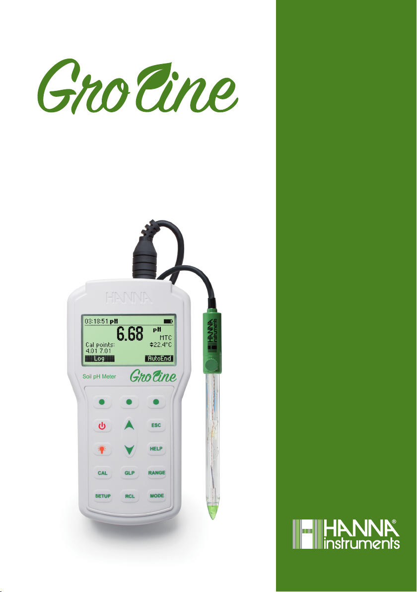
HI98168
Professional Soil pH Meter
INSTRUCTION MANUAL
Page 2

Dear
Customer,
Thank you for choosing a Hanna Instruments product.
Please read this instruction manual carefully before using the instrument.
This manual will provide you with the necessary information for correct use of the
instrument, as well as a precise idea of its versatility.
If you need additional technical information, do not hesitate to e‑mail us at
[email protected] or view our worldwide contact list at www.hannainst.com.
All rights are reserved. Reproduction in whole or in part is prohibited without the written consent of
the copyright owner, Hanna Instruments Inc., Woonsocket, Rhode Island, 02895, USA.
Page 3

PRELIMINARY EXAMINATION ..............................................................................................
SAFETY MEASURES ............................................................................................................
GENERAL DESCRIPTION ......................................................................................................
FUNCTIONAL DESCRIPTION ................................................................................................
SPECIFICATIONS ................................................................................................................
SOIL pH ............................................................................................................................
ORGANIC SUBSTRATE ........................................................................................................
IRRIGATION WATER ...........................................................................................................
NUTRIENT SOLUTION .........................................................................................................
OPERATIONAL GUIDE .........................................................................................................
pH CALIBRATION ...............................................................................................................
pH BUFFER TEMPERATURE DEPENDENCE ............................................................................
GOOD LABORATORY PRACTICE (GLP) ...................................................................................
SETUP ..............................................................................................................................
LOGGING ..........................................................................................................................
AUTOEND .........................................................................................................................
TEMPERATURE CALIBRATION (FOR TECHNICAL PERSONNEL ONLY) .........................................
PC INTERFACE ...................................................................................................................
BATTERIES REPLACEMENT ..................................................................................................
TEMPERATURE CORRELATION FOR pH SENSITIVE GLASS .......................................................
ELECTRODE CONDITIONING AND MAINTENANCE ..................................................................
TROUBLESHOOTING GUIDE ................................................................................................
ACCESSORIES ...................................................................................................................
TABLE OF CONTENTS
4
4
5
6
8
9
13
13
14
17
19
29
30
31
42
43
44
46
50
51
52
55
56
3
Page 4

Remove the instrument from the packing material and examine it carefully to make sure that no
damage has occurred during shipping. If there is any damage, please contact your local Hanna
Instruments Office.
Each instrument is supplied with:
•HI12923 Glass body, conical tip, refillable pH electrode with internal temperature sensor
•HI700663 Cleaning solution for soil deposits (1 pc.)
•HI700664 Cleaning solution for humus deposits (1 pc.)
•HI7051M Soil Test Solution (230 mL)
•HI920015 USB cable
•HI721319 ground auger
PRELIMINARY EXAMINATION
•pH 4.01 & 7.01 Buffer solutions (230 mL each)
•100 mL Beaker (2 pcs.)
•1.5V AA Batteries (4 pcs.)
•HI720161 Hard carrying case
•Instruction Manual and Quick Reference Guide
•Instrument Quality Certificate
Note: Save all packing material until you are sure that the instrument functions correctly. All
defective items must be returned in the original packing with the supplied accessories.
Before using this product, make sure that it is entirely suitable for your specific application and for
the environment in which it is used.
Operation of this instrument may cause interference to other electronic equipment, requiring the
operator to take steps to correct interference. Any variation introduced by the user to the supplied
equipment may degrade the instrument’s EMC performance.
To avoid damages or burns, do not put the instrument in microwave ovens. For your and the
instrument’s safety, do not use or store the instrument in hazardous environments.
SAFETY MEASURES
4
Page 5

HI98168 is a portable, pH and temperature meter specifically designed for direct soil measurement.
It is provided with a series of new diagnostic features which add an entirely new dimension to the
measurement of pH, by allowing the user to dramatically improve the reliability of the measurement:
• Seven standard buffers (pH 1.68, 4.01, 6.86, 7.01, 9.18, 10.01 and 12.45) for calibration.
• pH calibration up to five calibration points (see instrument specifications).
• Custom calibration with up to five custom buffers.
• Messages on the graphic LCD for an easy and accurate calibration.
• Cal Check™ Diagnostic features to alert the user when the electrode needs cleaning.
• Optional user enabled “Outside Calibration Range” warning.
• Monitoring of the electrode aging.
• User selectable “Calibration Time Out” to remind when a new calibration is necessary.
This meter is supplied with a pH electrode specifically designed for direct soil measurement.
HI12923 is a glass body, refillable, single junction pH electrode. This electrode has a triple ceramic
junction in the outer reference cell and the conic pH sensing tip is made with low temperature glass.
There is an integrated amplifier and built‑in temperature sensor for automatically temperature com‑
pensated pH readings.
Other features include:
• Log on demand up to 200 samples (100 pH and 100 mV).
• Auto Hold feature, to freeze first stable reading on the LCD.
• GLP feature, to view last calibration data for pH.
• PC interface.
GENERAL DESCRIPTION
5
Page 6
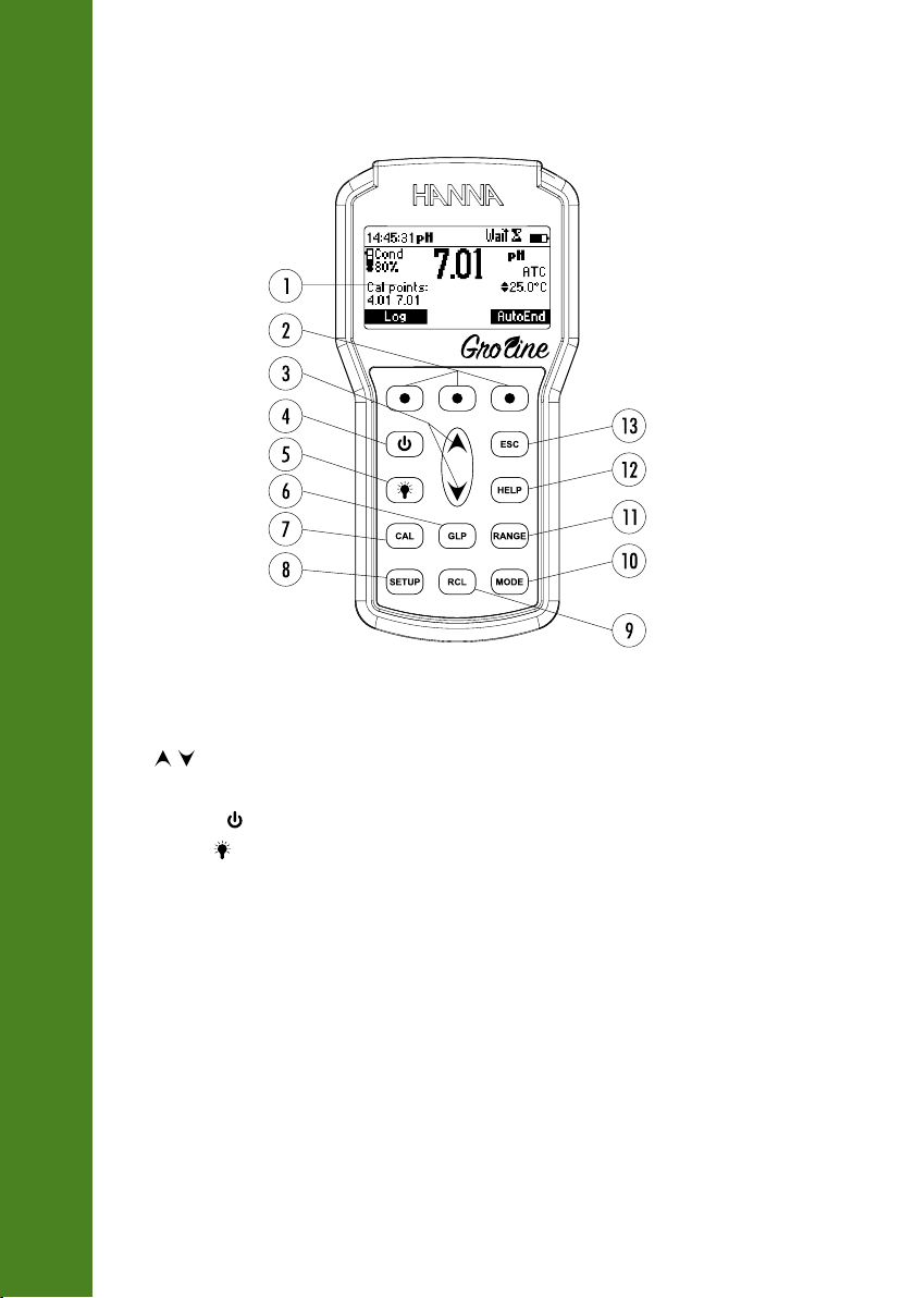
FRONT VIEW
Soil pH Meter
FUNCTIONAL DESCRIPTION
1) Liquid Crystal Display (LCD).
2) Functional keys.
3)
/ keys to scroll through calibration buffers, setup options, manual temperature compensation
and logged data.
4) ON/OFF (
5) LIGHT (
6) GLP key, to display Good Laboratory Practice information.
7) CAL key, to enter/exit calibration mode.
8) SETUP key, to enter/exit SETUP mode.
9) RCL key, to enter/exit view logged data mode.
10) MODE key to change pH resolution.
11) RANGE key, to switch between pH and mV range.
12) HELP key to enter/exit contextual help.
13) ESC to leave current mode, exit calibration, setup, help. etc.
) key, to turn the instrument ON and OFF.
) key to toggle display backlighting.
6
Page 7
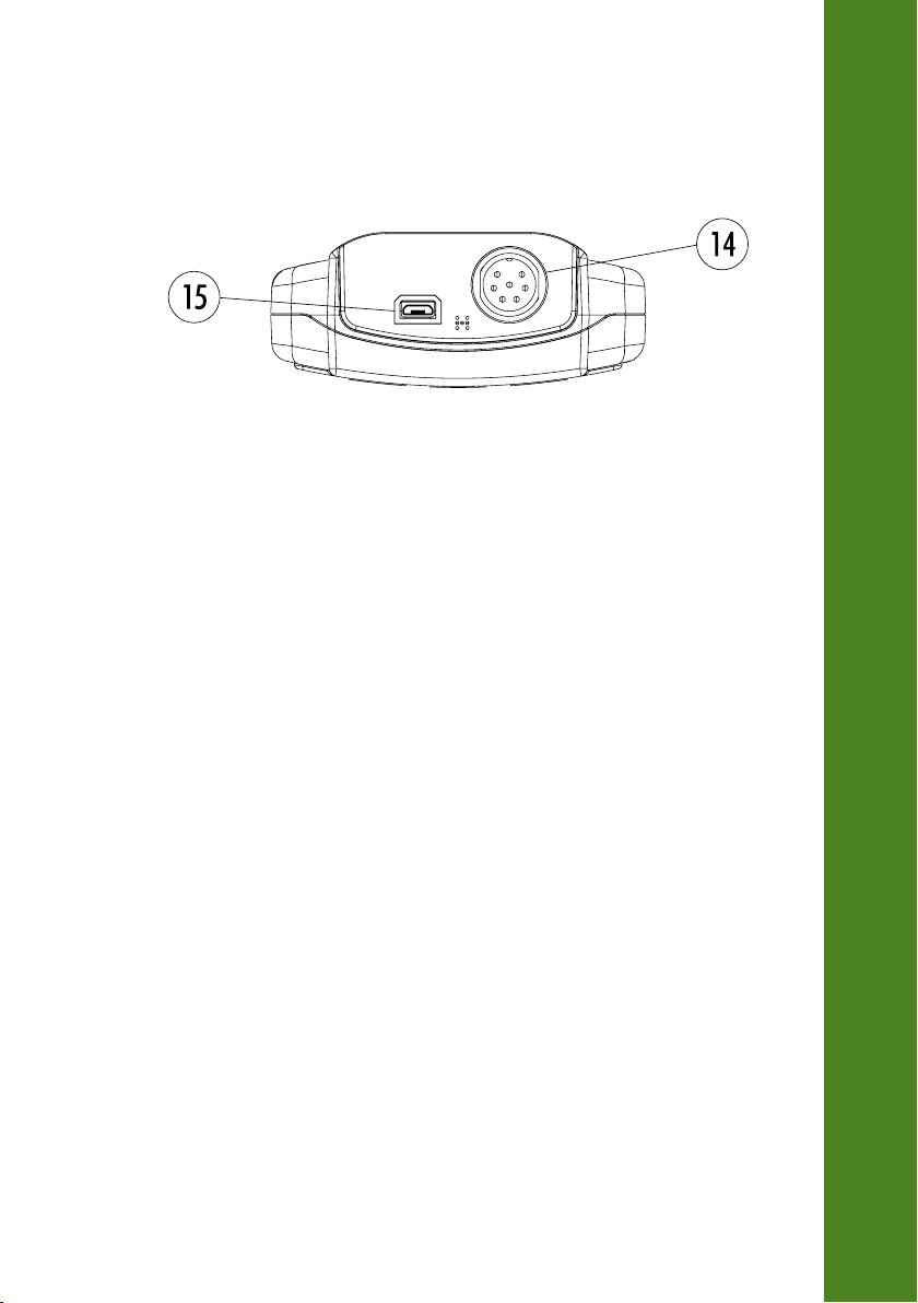
TOP VIEW
14) Electrode quick connect DIN connector.
15) USB connector.
FUNCTIONAL DESCRIPTION
7
Page 8

Temperature
SPECIFICATIONS
pH
Range ‑2.0 to 20.0 pH / ‑2.00 to 20.00 pH / ‑2.000 to 20.000 pH
Resolution 0.1 pH / 0.01 pH / 0.001 pH
Accuracy ±0.1 pH / ±0.01 pH / ±0.002 pH
Range ‑20.0 to 120.0 °C (‑4.0 to 248.0 °F)
Resolution 0.1 °C (0.1 °F)
Accuracy ±0.4 °C (±0.8 °F) (excluding probe error)
Range ±2000.0 mV
mV
pH Calibration
Slope Calibration From 80 to 110%
Temperature Compensation Automatic
pH Electrode HI12923 pH & temperature
Input Impedance 10¹² Ω
Battery Type/Life 1.5V AA batteries (4 pcs.) / approx. 200 hours of continuous use
Auto Power Off User selectable: 5, 10, 30, 60 minutes or disabled
Environment 0 to 50 °C (32 to 122 °F) max. RH 100% IP67
Accuracy
Resolution ±0.2 mV
Up to five point calibration, seven standard buffers available
(pH 1.68, 4.01, 6.86, 7.01, 9.18, 10.01, 12.45), and five custom
LOG On demand, 200 samples (100 pH and 100 mV)
without backlight (50 hours with backlight)
PC Interface opto‑isolated USB
Dimensions 185 x 93 x 35.2 mm (7.3 x 3.6 x 1.4”)
Weight 400 g (14.2 oz)
0.1 mV
buffers
8
Page 9
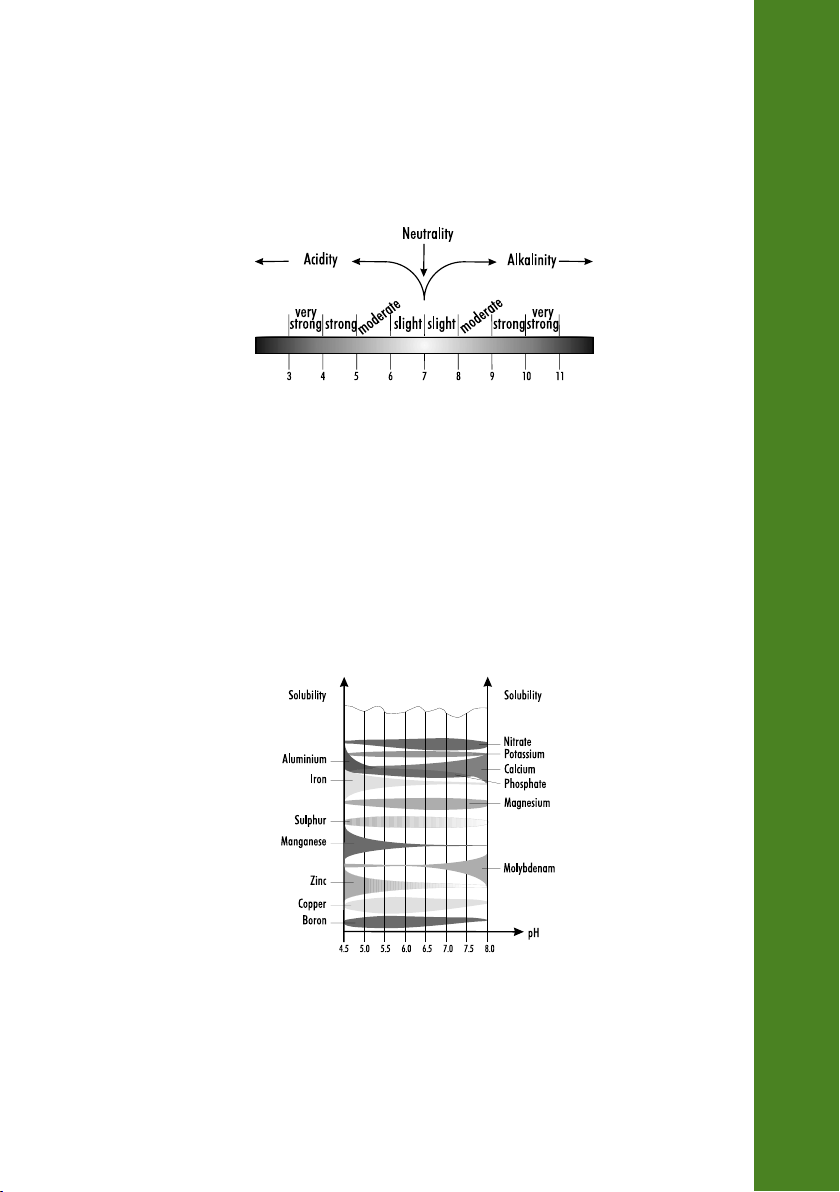
pH is the measure of the hydrogen ion concentration [H+]. The pH scale goes from 0 (very acidic) to 14 (basic)
with pH 7 being neutral. Soil can be acid, neutral or alkaline.
Fig. 1. shows the relationship between the scale of pH and types of soil. Most plants prefer a pH range from 5.5 to
7.5; but some species prefer more acid or alkaline soils. Nevertheless, every plant has a target for optimum growth.
Fig. 1. Types of soil according to the pH value
pH strongly influences the availability of nutrients and the presence of microorganisms and plants in the soil.
For example, fungi prefer acidic conditions whereas most bacteria, especially those supplying nutrients to the
plants, have a preference for moderately acidic or slightly alkaline soils. In fact, in strongly acidic conditions,
nitrogen fixing and the mineralization of vegetable residual is reduced.
Plants absorb the nutrients dissolved in the soil water and the nutrient solubility depends largely on the pH
value. Hence, the availability of elements is different at different pH levels (Fig. 2).
SOIL pH
Fig. 2. Solubility of the elements according to varying pH
9
Page 10

Each plant needs elements in different quantities and this is the reason why each plant requires a particular
range of pH to optimize its growth.
For example, iron, copper and manganese are not soluble in an alkaline environment. This means that plants
SOIL pH
needing these elements should theoretically be in an acidic type of soil. Nitrogen, phosphorus, potassium and
sulfur, on the other hand, are readily available in a pH range close to neutrality.
Abnormal pH values may increase the concentration of toxic elements for plants. For example, a plant may not
tolerate an excess of aluminum ions that may increase under acidic conditions.
When pH values are too far from neutral conditions a less permeable and more compact soil may result.
A Soil Management Strategy with regard to pH
• It is advisable to choose crops that are suitable for the soils pH range (e.g. in an acid soil, cultivate rice,
potato, strawberry).
• Add fertilizers that do not increase acidity (urea, calcium nitrate, ammonium nitrate and superphosphate)
or lower alkalinity (ammonium sulfate).
• A cost evaluation should be made prior to soil pH modification to determine cost of soil ameliorants versus
value of plants grown.
• pH modification may produce critical improvement in plant performance but may take too long or be short
lived.
For example, by adding lime, the effects in clay soil can last for as long as 10 years, but only 2‑3 years in a
sandy soil.
For an acid soil, we can use substances such as lime, dolomitic, limestone and marl, according to the nature
of the soil. See Table 1.
10
Soil Ameliorants Clay soil Silty soil Sandy soil
CaO 30‑50 20‑30 10‑20
Ca(OH)
CaMg(CO
Ca CO
3
2
3)2
39‑66 26‑39 13‑26
49‑82 33‑49 16‑33
54‑90 36‑54 18‑36
Table 1. Quantity (q/ha) of pure compound necessary to increase 1 unit of pH.
Page 11

Different naturally occuring minerals may effect soil pH same way but the method for correction may differ.
Take for example elevated soil pH:
‑ Soils rich with limestone:
Add organic matter (non‑organic ameliorants such as sulfur and sulfuric acid might not make economic sense
due to the large quantities needed).
‑ Alkaline‑saline soils:
An appropriate use of irrigation can provide positive results (drop‑irrigation) by flushing out salts.
If alkalinity is caused by sodium, it is recommended to add substances such as gypsum (calcium sulfate), sulfur
or other sulfuric compounds. In this case, a cost evaluation is necessary. See Table 2.
Soil ameliorants (pure compounds) Quantity (kg)
Calcium chloride: CaCl2 · 2H2O 85
Sulfuric acid: H
2SO4
57
Sulfur: S 19
Iron sulfate: Fe
Aluminum sulfate: Al
Table 2. Quantities provide the same result as 100 kg of gypsum.
(SO4)
· 7H2O 162
2
3
(SO4)
2
3
129
SOIL pH
Procedure for direct ground measurement
1) Verify meter is set up correctly and pH electrode is calibrated.
2) Dig, discarding 5 cm of topsoil.
3) Perforate the soil (with HI721319 soil auger) to a depth of about 20 cm or more.
4) If the soil is dry, moisten it with a small amount of distilled water
5) Wash the electrode with tap water (not distilled).
6) Insert the electrode pushing it slightly into the soil to ensure proper contact.
7) Observe the measurement.
8) Wash the electrode with tap water (not distilled) and (using a finger) gently remove any soil remaining
on the electrode (avoid using a rag or cloth).
9) Repeat the procedure in different locations in the field.
10) Consider the average of the measured data.
11
Page 12

For best result, it is advisable to measure the pH of a soil solution, using a sample of soil and soil preparation
solution HI7051; it is better to use this procedure if you have to test a stony field in which you risk damaging
the electrode.
SOIL pH
Procedure for the measurement of soil solution (1:2,5)
A) Verify meter is set up corecctly and pH electrode is calibrated.
B) Sampling
1) Extracting Soil Sample.
Take 1 sample per 1000 m2 (0.25 acre) of homogeneous area.Even for small areas, 2 samples are recom‑
mended (the more the samples, the better the end‑results, because the result is more representative).
2) Avoid extracting samples from soil presenting obvious anomalies and consider them separately.
3) Sample quantity:
Take the same quantity of soil for each sample. For example, use bags with similar dimensions (1 bag per
sample).
4) Depth of extraction:
General: dig and discard 5 cm (2”) of topsoil.
Herbaceous crops: from 20 to 40 cm of depth (8” to 16”).
Orchards: from 20 to 60 cm of depth (8” to 24’’).
5) Spread the soil samples on the pages of a newspaper and let the soil dry in a shady place or put it in an
oven at 40 °C.
6) Crumble the dried soil and mix all the samples together to obtain a homogeneous mixture, discarding stones
and vegetable residues.
7) From this mixture, take the soil sample for analysis.
12
C) Soil solution preparation and measurement
1) Sift the soil at 2 mm.
2) Weigh 10 g of soil and put it in 25 ml of soil preparation solution HI7051 (use the apposite beaker) or
20 g of soil per 50 ml of soil preparation solution HI7051.
3) Mix for 30 seconds.
4) Wait for about 5 minutes.
5) Mix again and measure the pH of the solution.
Page 13

The pH measurement of organic substrates is important in greenhouses and nursery growing pots. pH should
be checked at the outset to make sure that the pH of the substrate bought is that desired (pH can change if too
much time elapses from the date of packaging to the moment of utilization).
A) Verify pH meter is set up correctly and pH electrode is calibrated.
B) Direct measurement in pot:
If the substrate is dry, add a little distilled water. Insert the electrode into the soil and take measurement.
C) Measurement of the organic substrate solution (1:2):
Let the substrate dry and discard the coarse vegetable residues and pebbles.
Prepare a solution composed of 1 part of mould and 2 parts of HI7051 solution (for example: fill the beaker
with the substrate up to 50 ml, press it gently, empty the content in another container and add 100 ml of
HI7051 solution).
Mix for 30 seconds and then wait for 5 minutes. Mix again and measure the pH of the solution.
ORGANIC SUBSTRATE
The quality of irrigation water is a very important factor. If the pH value is very far from pH 7, it is possible that
other anomalies are present.
Ranges for evaluation of water quality:
‑ 6 to 8.5 pH: good, it can be utilized without problems.
‑ 5 to 6 pH or 8.5 to 9 pH: sufficient, sensitive crops could have problems.
‑ 4 to 5 pH or 9 to 10 pH: Use carefully, avoid wetting the vegetation/avoid use if possible.
‑ pH<4 or pH>10: Other anomalies that have to be identified via chemical analysis. Do not use for irrigation.
IRRIGATION WATER
13
Page 14

A rational fertilization program is required for optimum plant growth in greenhouses. The pH value of the nutrient
solution (water + fertilizer) has to meet the plants need.
If a fertirrigation system with automatic pH control is used, ensure that it is functioning properly.
Check the pH of the irrigation solution as well as any recycled solution.
Table 3. tabulates optimum pH value for various plants.
ORCHARD PLANTS
Preferred pH Range Preferred pH Range
NUTRIENT SOLUTION
Apple 5‑6.5 Orange 5‑7
Apricot 6‑7 Peach 6‑7.5
Cherry 6‑7.5 Pear 6‑7.5
Grapefruit 6‑7.5 Plum 6‑7.5
Grapevine 6‑7 Pomegranate 5.5‑6.5
Lemon 6‑7 Walnut 6‑8
Nectarine 6‑7.5
VEGETABLES AND HERBACEOUS CULTIVATIONS
Preferred pH Range Preferred pH Range
Artichoke 6.5‑7.5 Pepper 6‑7
Asparagus 6‑8 Early Potato 4.5‑6
Barley 6‑7 Late Potato 4.5‑6
Bean 6‑7.5 Sweet Potato 5.5‑6
Brussels Sprout 6‑7.5 Pumpkin 5.5‑7.5
Early carrot 5.5‑7 Rice 5‑6.5
Late carrot 5.5‑7 Soybean 5.5‑6.5
Cucumber 5.5‑7.5 Spinach 6‑7.5
Egg Plant 5.5‑7 Strawberry 5‑7.5
Lettuce 6‑7 String 6‑7.5
Maize 6‑7.5 Sugar beet 6‑7
Melon 5.5‑6.5 Sunflower 6‑7.5
Oat 6‑7 Tomato 5.5‑6.5
Onion 6‑7 Watermelon 5.5‑6.5
Pea 6‑7.5 Wheat 6‑7
14
Page 15
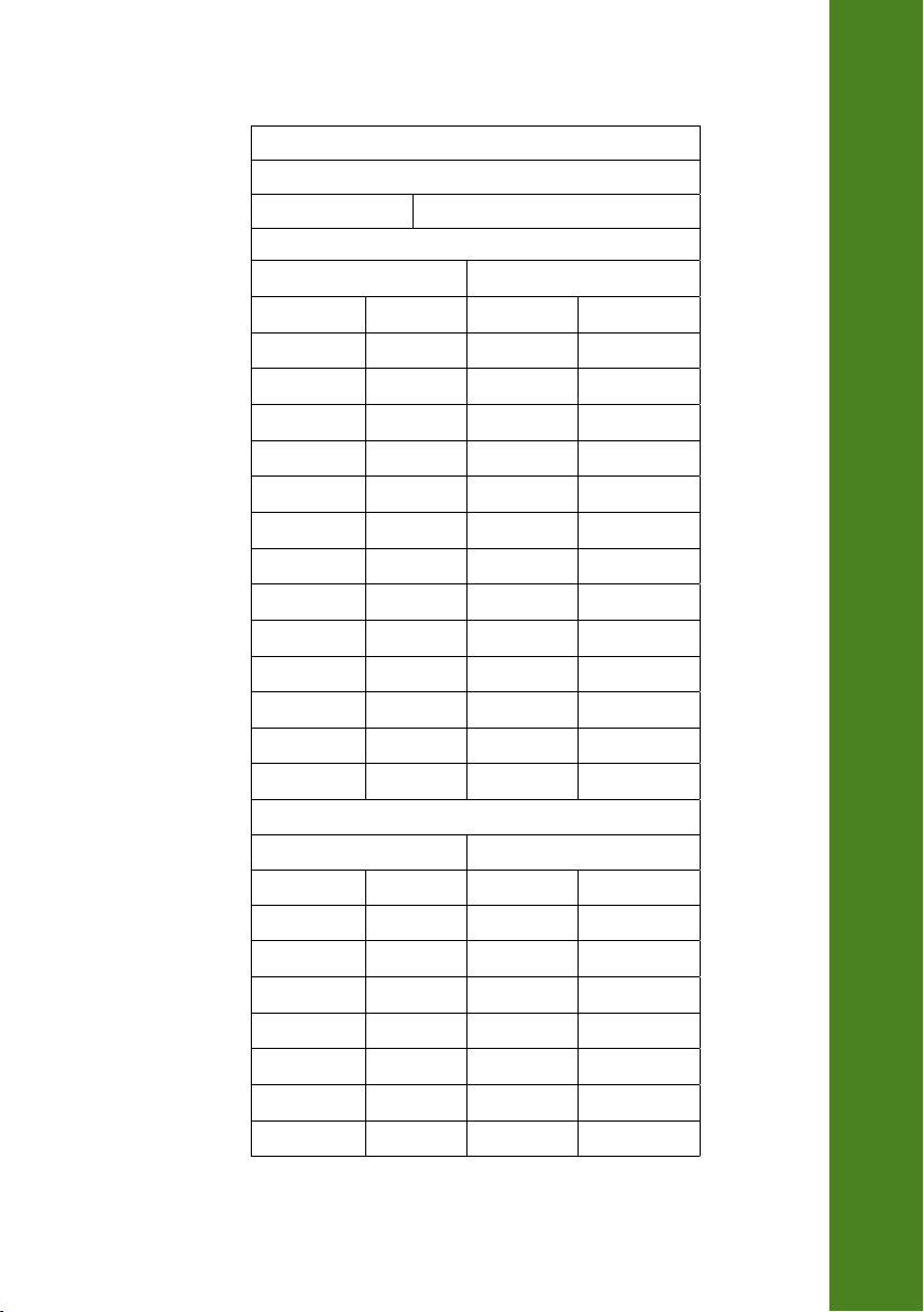
LAWN
Preferred pH Range
Lawn 6‑7.5
GARDEN PLANTS AND FLOWERS
Preferred pH Range Preferred pH Range
Acacia 6‑8 Ligustrum 5‑7.5
Acanthus 6‑7 Magnolia 5‑6
Amaranth 6‑6.5 Narcissus 6‑8,5
Bougainvillea 5.5‑7.5 Oleander 6‑7.5
Dahlia 6‑7.5 Paulownia 6‑8
Erica 4.5‑6 Portulaca 5.5‑7.5
Euphorbia 6‑7 Primula 6‑7.5
Fuchsia 5.5‑7.5 Rhododendron 4.5‑6
Gentian 5‑7.5 Roses 5.5‑7
Gladiolus 6‑7 Sedum 6‑7.5
Hellebore 6‑7.5 Sunflower 5‑7
Hyacinth 6.5‑7.5 Tulip 6‑7
Iris 5‑6.5 Viola 5.5‑6.5
Juniper 5‑6.5
HOUSE PLANTS
Preferred pH Range Preferred pH Range
Abutilon 5.5‑6.5 Gardenia 5‑6
African violet 6‑7 Geranium 6‑8
Anthurium 5‑6 Hibiscus 6‑8
Araucaria 5‑6 Jasmine 5.5‑7
Azalea 4.5‑6 Kalanchoe 6‑7.5
Begonia 5.5‑7.5 Mimosa 5‑7
Camellia 4.5‑5.5 Orchid 4.5‑5.5
Croton 5‑6 Palms 6‑7.5
NUTRIENT SOLUTION
15
Page 16

Cyclamen 6‑7 Peperomia 5‑6
Dieffenbachia 5‑6 Philodendron 5‑6
Dracaena 5‑6 Yucca 6‑7.5
Freesia 6‑7.5
Table 3. Optimum pH for various Plants.
NUTRIENT SOLUTION
16
Page 17

INITIAL PREPARATION
The instrument is supplied complete with 1.5V AA (4 pcs.) batteries. For placing the batteries inside
the meter, see page 50.
Make sure that the protective micro USB cover is used when not connected to a computer to ensure
waterproof protection.
For HI98168 connect the pH/temperature electrode to the DIN connector.
Turn the instrument ON by pressing ON/OFF key.
At start‑up the display will show the Hanna Instruments logo for a few seconds followed by the
percentage indication of the remaining battery life, then enters the measurement mode.
After measurement switch the instrument off, clean the electrode and store it with a few drops of
HI70300 storage solution in the protective cap (see page 53).
The Auto Power Off feature turns the instrument off after a set period (default 30 min) with no button
pressed to save battery life. To set another period or to disable this feature, see SETUP menu on
page 31.
The Auto Light Off backlight feature turns the backlight off after a set period (default 1 min) with
no buttons pressed. To set another period or to disable this feature, see SETUP menu on page 31.
pH MEASUREMENTS
To take a pH measurement remove the electrode protective cap and simply submerge the tip of the
electrode (4 cm/1½") into the sample to be tested.
Press RANGE key to choose between pH and mV ranges.
Use MODE key to select the pH resolution.
Allow time for the electrode to adjust and reading to stabilize (hourglass symbol turns off).
OPERATIONAL GUIDE
17
Page 18

On the pH screen are displayed:
• pH reading with the selected resolution.
• Temperature reading in the selected unit (°C or °F).
OPERATIONAL GUIDE
• Electrode condition during the calibration day.
• The buffers used in last pH calibration (if feature is enabled in SETUP).
• Battery level indicator.
• Available functional keys.
In order to take more accurate pH measurements, make sure that the instrument is calibrated (see
page 19 for calibration details).
It is recommended that the electrode is always kept moist and rinsed thoroughly with the sample to
be measured before use.
The pH reading is directly affected by temperature. For accurate pH measurements, temperature
must be taken into consideration. If the sample temperature is different from the temperature at
which the pH electrode was kept, allow a few minutes to reach thermal equilibrium.
TEMPERATURE MEASUREMENTS
For HI98168 the temperature sensor is connected through DIN socket.
18
Note: The temperature can be displayed in Celsius degrees (ºC) or in Fahrenheit degrees
(ºF) (see SETUP for details, page 31).
BACKLIGHT FEATURE
The instrument is provided with a Backlight feature, which can be easily toggled on and off through
the keyboard by pressing LIGHT.
Note: The backlight automatically shuts off after a set period (see SETUP for details,
page 31) with no buttons pressed.
Page 19

It is recommended to calibrate the instrument frequently, especially if high accuracy is required.
The pH range should be recalibrated:
• Whenever the pH electrode is replaced.
• At least once a week.
• After testing aggressive chemicals.
• When calibration alarm time out is expired ‑ “CAL DUE” blinks (if feature is enabled in
SETUP).
• If “Outside Cal Range” message blinks during pH measurement (the measurement range is
not covered by current calibration, if feature is enabled in SETUP).
PROCEDURE
HI98168 instrument offers a choice of seven standard buffers (pH 1.68, 4.01, 6.86, 7.01, 9.18, 10.01
and 12.45). The meter allow the user to set up to five custom buffers. The custom buffers are the
buffer values at 25 °C.
When a custom buffer is selected during calibration, the Custom functional key is displayed on the
LCD. Press Custom key in order to enter custom buffer changing mode. Use / keys to change
the value in a ±1.00 pH window, in according with the temperature reading and then Accept. Press
ESC to leave custom buffers value unchanged.
For accurate pH measurements, it is recommended to perform a calibration with buffers that bracket
the expected pH value. At least, two point calibration is recommended.
The instrument will automatically skip the buffers used during calibration and the buffers which are
in a ±0.2 pH window around one of the calibrated buffers.
• Remove protective cap and rinse the electrode with distilled or deionized water.
• Pour small quantities of selected buffers solutions into clean beakers. For accurate calibration use
two beakers for each buffer solution, the first one for rinsing the electrode and the second one
for calibration.
pH CALIBRATION
19
Page 20
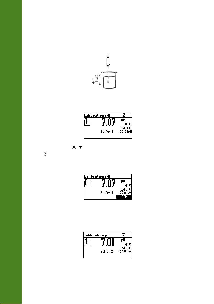
FIVE POINT CALIBRATION
• Immerse the pH electrode approximately 4 cm (1½”) into a buffer solution of your choice
(pH 1.68, 4.01, 6.86, 7.01, 9.18, 10.01, 12.45 or a custom buffer) and stir gently.
pH CALIBRATION
• Press CAL. The instrument will display the measured pH, the LCD first expected buffer and the
temperature reading.
• If necessary, press the / keys to select a different buffer value.
• The “ ” tag will blink on the LCD until the reading is stable.
• When the reading is stable and within range of the selected buffer, CFM functional key is
displayed.
20
• Press CFM to confirm first point.
• The calibrated value and the second expected buffer value is then displayed on the LCD.
Page 21
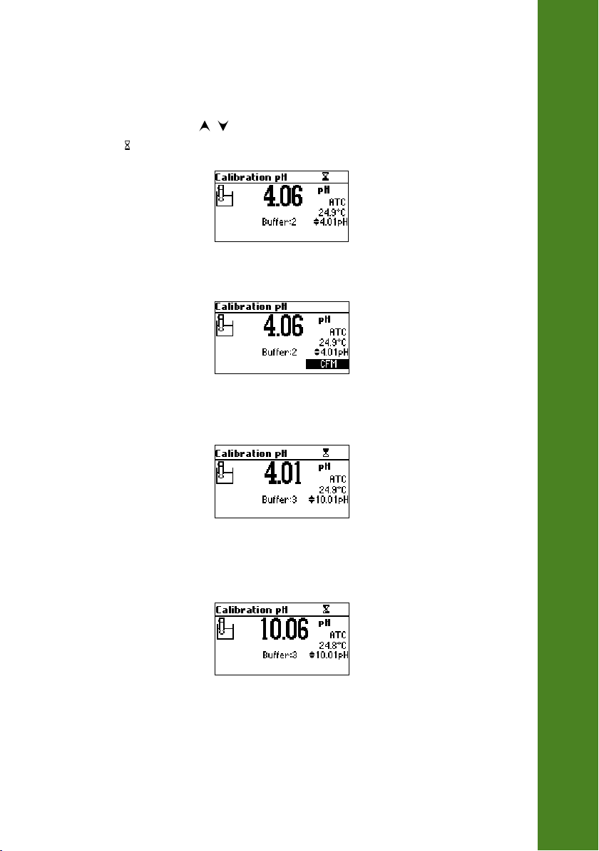
• After the first calibration point is confirmed, immerse the pH electrode probe approximately
4 cm (1½”) into the second buffer solution and stir gently.
• If necessary, press the / keys to select a different buffer value.
• The “ ” tag will blink on the LCD until the reading is stable.
• When the reading is stable and within range of the selected buffer, the CFM functional key is
displayed.
• Press CFM to confirm calibration.
• The calibrated value and the third expected buffer value will be displayed.
pH CALIBRATION
• After the second calibration point is confirmed, immerse the pH electrode approximately
4 cm (1½”) into the third buffer solution and stir gently.
21
Page 22
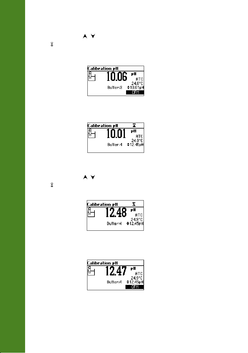
• If necessary, press the / keys to select a different buffer value.
• The “ ” tag will blink on the LCD until the reading is stable.
• When the reading is stable and within range of the selected buffer, the CFM functional key is
displayed.
pH CALIBRATION
• Press CFM to confirm calibration.
• The calibrated value and the fourth expected value will be displayed.
• After the third calibration point is confirmed, immerse the pH electrode approximately
4 cm (1½”) into the fourth buffer solution and stir gently.
• If necessary, press the / keys to select a different buffer value.
• The “ ” tag will blink on the LCD until the reading is stable.
22
• When the reading is stable and within range of the selected buffer, the CFM functional key is
displayed.
Page 23
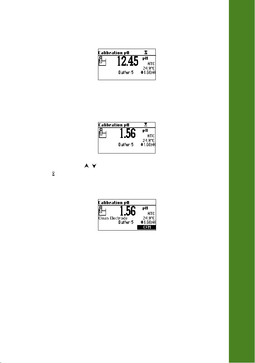
• Press CFM to confirm calibration.
• The calibrated value and the fifth expected buffer will be displayed.
• After the fourth calibration point is confirmed, immerse the pH electrode approximately
4 cm (1½”) into the fifth buffer solution and stir gently.
• If necessary, press the / keys to select a different buffer value.
• The “ ” tag will blink on the LCD until the reading is stable.
• When the reading is stable and within range of the selected buffer, the CFM functional key is
displayed.
pH CALIBRATION
• Press CFM to confirm calibration.
• The instrument stores the calibration values and returns to normal measurement mode.
23
Page 24
FOUR, THREE, TWO or ONE POINT CALIBRATION
• Proceed as described in “FIVE POINT CALIBRATION” section.
• Press CAL or ESC after the appropriate accepted calibration point. The instruments will return to
measurement mode and will memorize the calibration data.
FIRST POINT MODE
Two SETUP options are available to determine how the previous calibration will be affected by a
pH CALIBRATION
subsequent one point calibration. These options are replace or offset.
If the Replace option is selected, the slopes between current buffer and nearest lower and higher
buffers will be recalculated.
If the Offset option is selected, an electrode offset correction is performed keeping unchanged the
existing slopes.
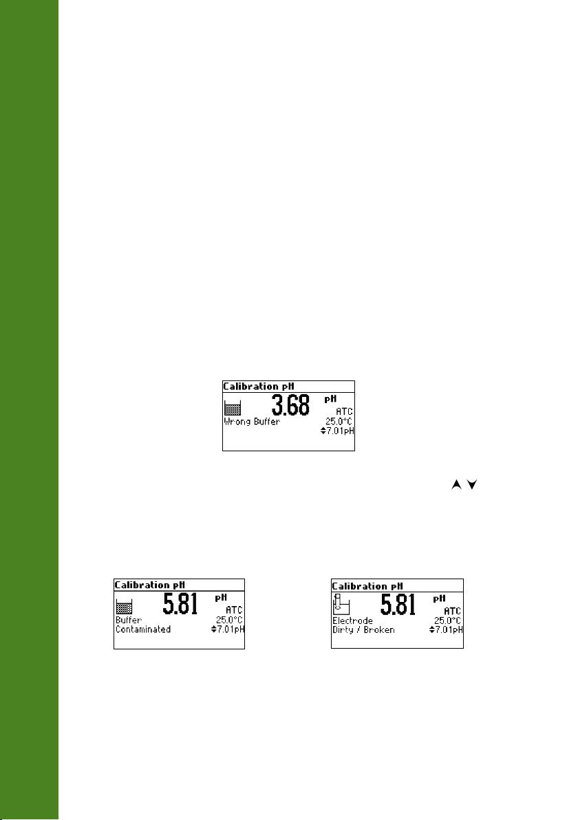
ERROR SCREENS
Wrong buffer
The calibration cannot be confirmed.
24
The pH reading is not within range of the selected buffer. Select another buffer using the / keys
or change the buffer.
Electrode Dirty/Broken alternatively with Buffer Contaminated
The calibration cannot be confirmed.
The offset of the electrode is not in the accepted range. Check if the electrode is broken or clean it
following the Cleaning Procedure (see page 45). Check the quality of the buffer. If necessary, change
the buffer.
Page 25
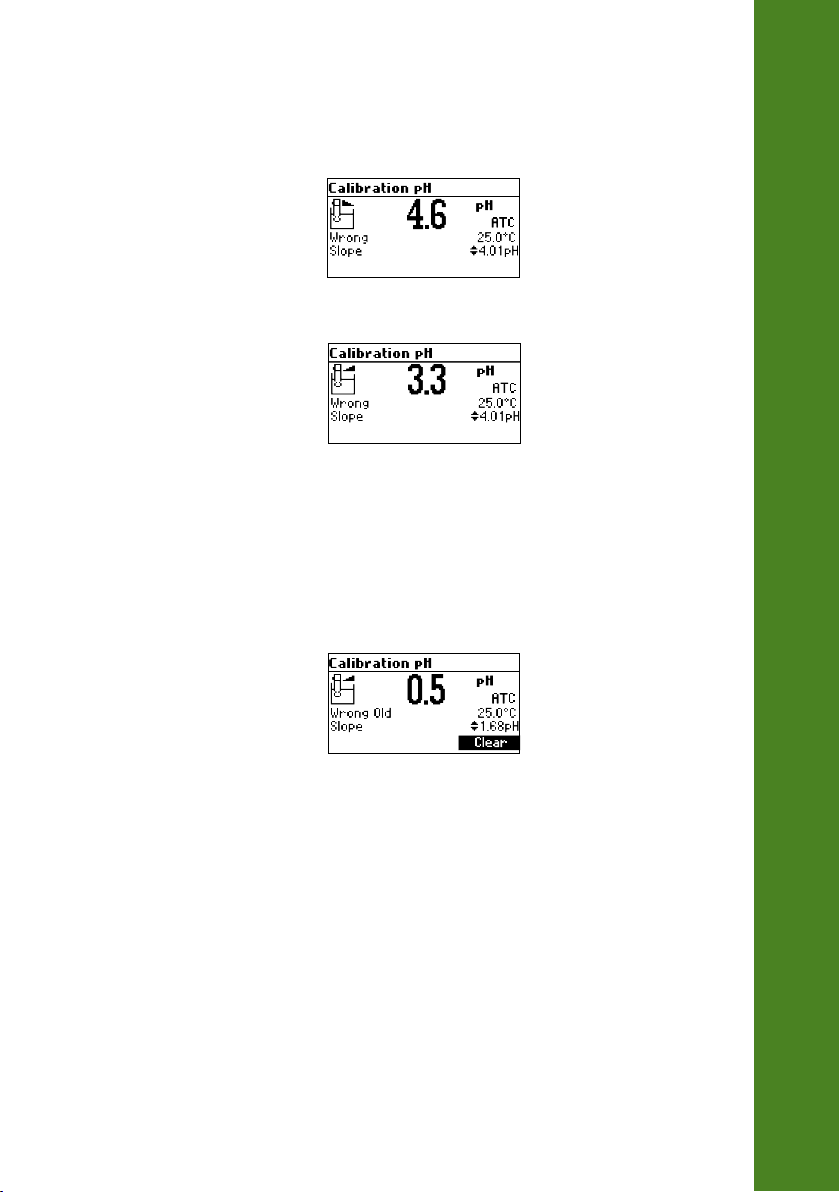
Wrong slope
The calibration cannot be confirmed.
The evaluated slope is less than the lowest accepted value (80% of default slope).
The evaluated slope is more than the highest accepted value (110 % of default slope).
Wrong old slope
An inconsistency between new and previous (old) calibration is detected. Clear old calibration
parameters and proceed with the calibration from the current point. The instrument will keep all
confirmed values during current calibration.
pH CALIBRATION
Note: For one point calibration the electrode condition is not displayed in the measurement
screen. Each time a buffer is confirmed, the new calibration parameters replace the old
calibration parameters of the corresponding buffer.
25
Page 26
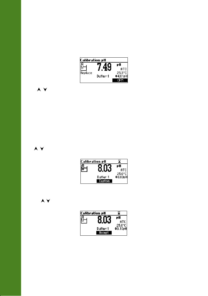
If the current confirmed buffer has no correspondence in the existing stored calibration and this is
not full, the current buffer is added to the existing stored calibration.
If the existing stored calibration is full (five calibration points), after confirming the calibration point,
the instrument will ask which buffer will be replaced by current buffer.
pH CALIBRATION
Press / keys to select another buffer to be replaced.
Press CFM to confirm the buffer that will be replaced.
Press CAL or ESC to leave replace mode. In this case, the buffer will not be memorized.
Note: The replaced buffer is not removed from calibration list and it can be selected for the
next calibration points.
WORKING WITH CUSTOM BUFFERS
If at least one custom buffer was set in SETUP menu, it can be selected for calibration by pressing
the / keys. The Custom functional key will be displayed.
26
Press Custom if you want to adjust the buffer value according with current temperature.
Use the / keys to change the buffer value.
Press Accept to accept new value or ESC to exit changing mode.
Note: Custom buffer value can be adjusted in a ±1.00 pH window, around the set value.
Page 27
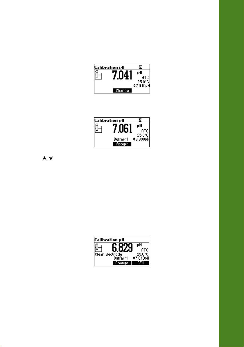
WORKING WITH MILI pH BUFFERS
If calibration is invoked from mili pH range, the calibration buffer can be modified in a ±0.020 pH
range in according with the label on the calibration buffer.
Press Change to enter buffer adjust mode.
Use / keys to change the buffer value.
Press Accept to accept new value or ESC to exit adjusting mode.
CLEAR CALIBRATION
Press Clear functional key when displayed to clear old calibrations.
All old calibrations, are cleared and the instrument continues calibration. The points confirmed in
current calibration are kept.
pH CALIBRATION
Note: If Clear calibration is invoked during the first calibration point, the instrument returns
to measurement mode.
27
Page 28
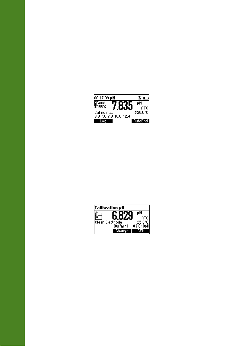
ELECTRODE CONDITION
The display is provided with an icon, and a numeric value (unless the feature is disabled) which gives
an indication of the electrode status after calibration.
The “condition” remains active until the end of the calibration day.
Note: The electrode condition is evaluated only if current calibration includes at least two
pH CALIBRATION
standard buffers.
CLEAN ELECTRODE WARNING
Each time pH calibration is performed, the instrument internally compares the new calibration with
the one previously stored.
When this comparison indicates a significant difference, the “Clean Electrode” warning message is
displayed to advise the user that the pH electrode may need to be cleaned (see ELECTRODE
CONDITIONING AND MAINTENANCE section for details, page 52).
28
After cleaning, perform a new calibration.
Note: If the calibration data are cleared, the comparison is done with the default values.
Page 29

The temperature has an effect on pH. The calibration buffer solutions are affected by temperature
changes to a lesser degree than normal solutions.
During calibration the instrument will automatically calibrate to the pH value corresponding to the
measured temperature.
TEMP pH BUFFERS
°C °F 1.68 4.01 6.86 7.01 9.18 10.01 12.45
0 32 1.67 4.01 6.98 7.13 9.46 10.32 10.38
5 41 1.67 4.00 6.95 7.10 9.39 10.25 13.18
10 50 1.67 4.00 6.92 7.07 9.33 10.18 12.99
15 59 1.67 4.00 6.90 7.05 9.27 10.12 12.80
20 68 1.68 4.00 6.88 7.03 9.22 10.06 12.62
25 77 1.68 4.01 6.86 7.01 9.18 10.01 12.45
30 86 1.68 4.02 6.85 7.00 9.14 9.96 12.29
35 95 1.69 4.03 6.84 6.99 9.11 9.92 12.13
40 104 1.69 4.04 6.84 6.98 9.07 9.88 11.98
45 113 1.70 4.05 6.83 6.98 9.04 9.85 11.83
50 122 1.71 4.06 6.83 6.98 9.01 9.82 11.70
55 131 1.72 4.08 6.84 6.98 8.99 9.79 11.57
60 140 1.72 4.09 6.84 6.98 8.97 9.77 11.44
65 149 1.73 4.11 6.84 6.99 8.95 9.76 11.32
70 158 1.74 4.12 6.85 6.99 8.93 9.75 11.21
75 167 1.76 4.14 6.86 7.00 8.91 9.74 11.10
80 176 1.77 4.16 6.87 7.01 8.89 9.74 11.00
85 185 1.78 4.17 6.87 7.02 8.87 9.74 10.91
90 194 1.79 4.19 6.88 7.03 8.85 9.75 10.82
95 203 1.81 4.20 6.89 7.04 8.83 9.76 10.73
pH BUFFER TEMPERATURE DEPENDENCE
During calibration the instrument will display the pH buffer value at 25 °C.
29
Page 30
GLP is a set of functions that allows storage and retrieval of data regarding the maintenance and
status of the electrode.
All data regarding the pH calibration is stored for the user to review when necessary.
EXPIRED CALIBRATION
The instrument is provided with a real time clock (RTC), in order to monitor the time elapsed since
the last pH calibration.
The real time clock is reset every time the instrument is calibrated and the “Expired Calibration”
status is triggered when the instrument detects a calibration time out. The “CAL DUE” tags will start
blinking to warn the user that the instrument should be recalibrated.
The calibration time out can be set (see SETUP for details, pages 31‑32) from 1 to 7 days or can be
disabled.
For example, if a 4 days time out has been selected, the instrument will issue the alarm exactly
4 days after the last calibration.
However, if at any moment the expiration value is changed (e.g. to 5 days), then the alarm will be
GOOD LABORATORY PRACTICE (GLP)
immediately recalculated and appear 5 days after the last calibration.
Notes: When the instrument is not calibrated or calibration is cleared (default values
loaded) there is no “Expired Calibration”, and the display always shows the “CAL DUE”
tags blinking.
When an abnormal condition in the RTC is detected, the instrument forces the “Expired
Calibration” status.
30
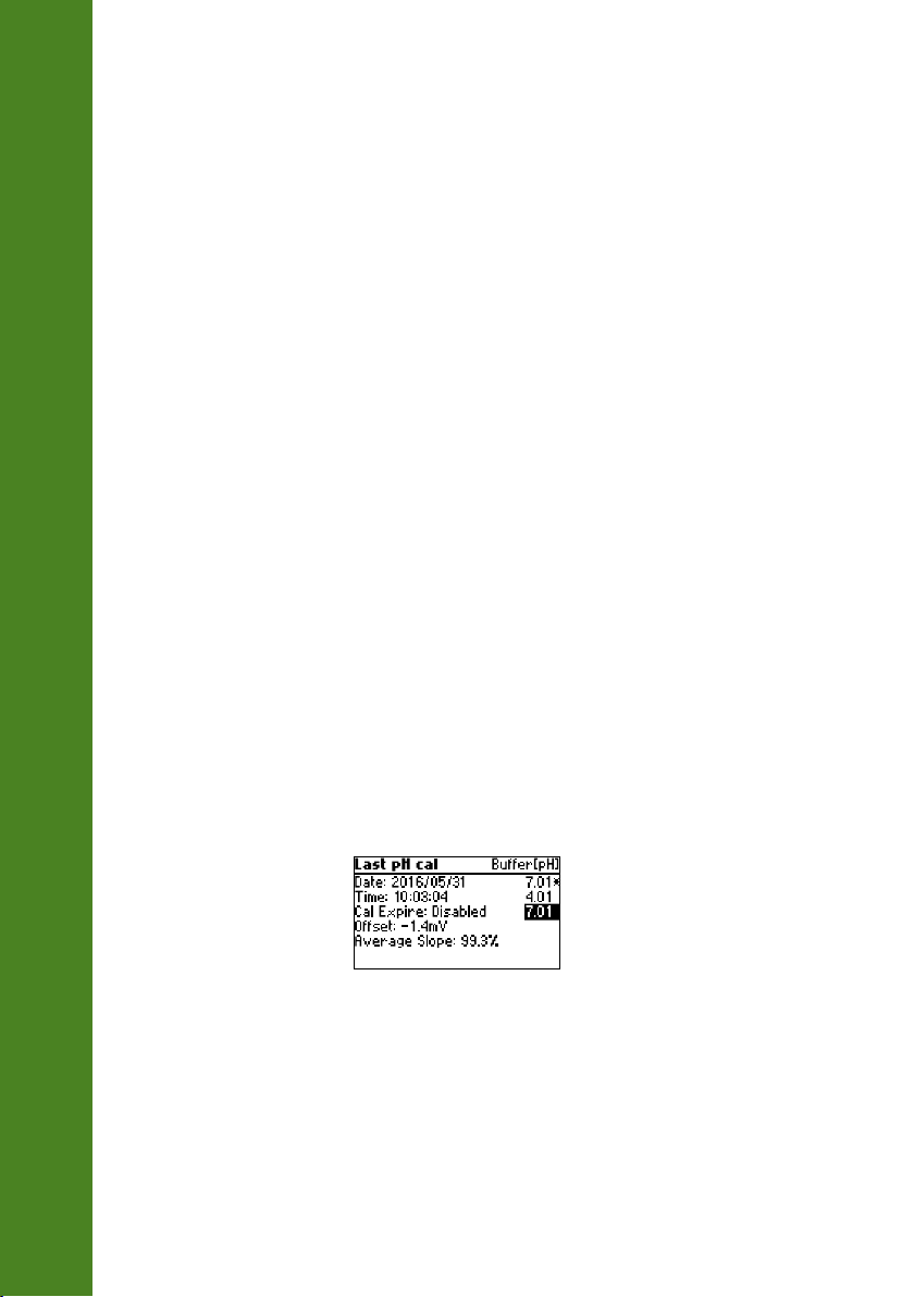
LAST pH CALIBRATION DATA
The last pH calibration data is stored automatically after a successful calibration.
To view the pH calibration data, press GLP when the instrument is in the measurement mode.
The instrument will display a lot of data including calibration buffer, offset, slope, electrode
condition.
Note: Buffers displayed in video inverse mode are from previous calibrations. The custom
buffers are marked with an “*” on the right side of the buffer value. “No user calibration”
message is displayed if all calibration are cleared or the instrument was not calibrated.
Page 31

Setup mode allows viewing and modifying the measurement parameters.
The following table lists the general SETUP parameters, their valid range and the factory default
settings.
Description Valid value Default
Backlight Backlight Level 0 to 7 4
Contrast Contrast Level 0 to 20 10
Auto light off Time until backlight is ON 1, 5, 10, 30 min 1
Auto power off Time after the instrument is
powered OFF
Date/Time 01.01.2000 to 12.31.2099
Time Format AM/PM or 24 hours 24 hours
Date Format DD/MM/YYYY
Language Message Display Language Up to four languages English
Temperature Unit °C or °F °C
Beep ON Beeper Status Enabled or Disabled Disabled
Instrument ID Instrument Identification 0000 to 9999 0000
Baud Rate Serial Communication 600, 1200, 2400, 4800,
Meter Information Displays General Information
Disabled
5, 10, 30, 60 min
00:00 to 23:59
MM/DD/YYYY
YYYY/MM/DD
YYYY‑MM‑DD
Mon DD, YYYY
DD‑Mon‑YYYY
YYYY‑Mon‑DD
9600
current
date/time
YYYY/MM/DD
9600
SETUP
30
31
Page 32

The following table lists the specific range parameters.
SETUP
Item Description Valid value Default
Calibration Timeout Number of days after
Calibration warning is
displayed
First point mode Management of
1 point calibration
Custom buffer Custom buffer setting Max. 5 buffers No
View calibration
points
Display Out of Cal.
Range Warning
Display calibration
points
Disable, 1 to 7 days Disable
Replace or offset Replace
Enable or disabled Enable
Enable or disabled Enable
32
Page 33
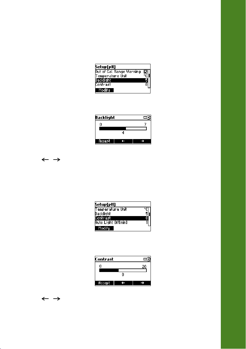
GENERAL PARAMETER SCREENS
Backlight
Highlight Backlight.
Press Modify.
Use / keys to change the intensity then press Accept to confirm.
Press ESC to leave without changing.
Contrast
Highlight Contrast.
SETUP
Press Modify.
Use / keys to change contrast then press Accept to confirm.
Press ESC to leave without changing.
33
Page 34
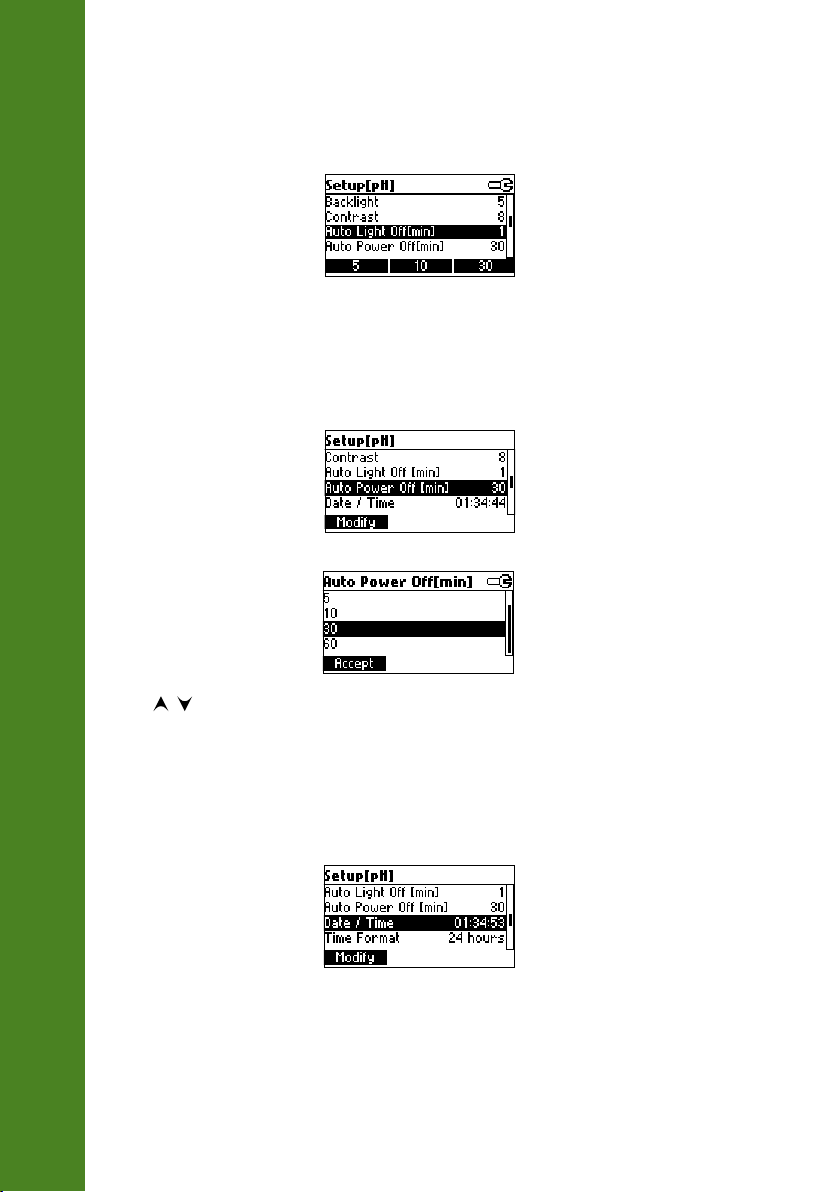
Auto Light Off
Highlight Auto Light Off.
SETUP
Press 5, 10 or 30 to change settings.
Auto Power Off
Highlight Auto Power Off.
Press Modify.
34
Press / keys to select interval then press Accept.
Press ESC to leave without changing.
Date/Time
Highlight Date/Time.
Page 35
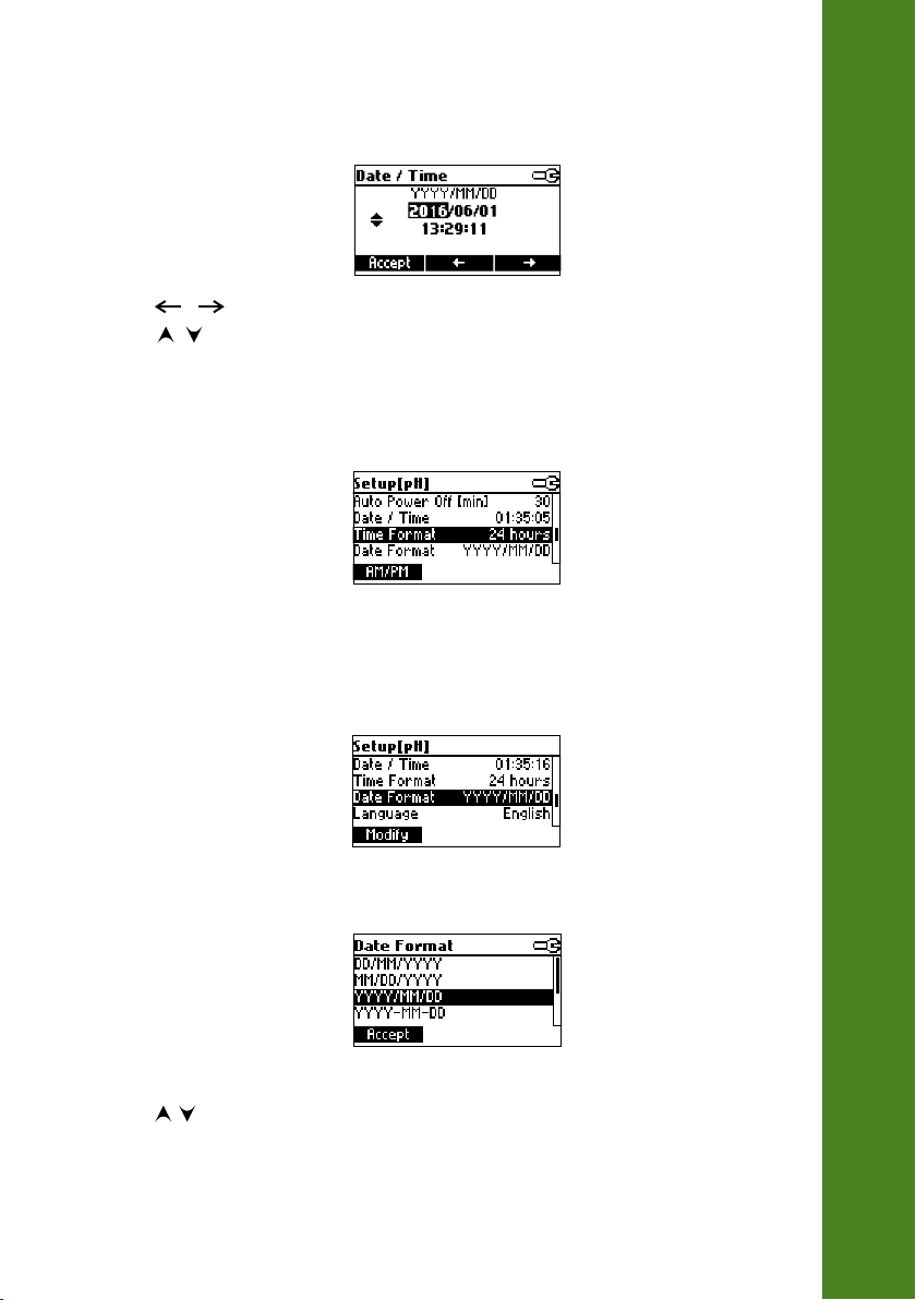
Press Modify.
Use / keys to select item.
Use / keys to change focused values.
Press Accept to confirm new setting, or ESC to leave without changing.
Time Format
Highlight Time Format.
Press displayed functional key to change the option.
Date Format
Highlight Date Format.
SETUP
Press Modify.
Use / keys to select date format then press Accept.
Press ESC to leave without changing.
35
Page 36
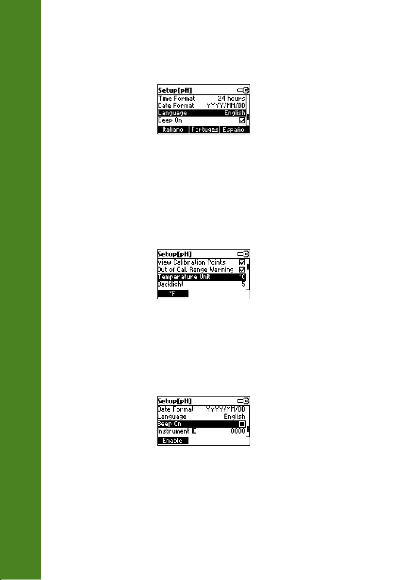
Language
Highlight Language.
SETUP
Use the desired functional key to change the option. Wait until new language is loaded. If language
load fails the instrument will try to reload current language.
If any language can’t be loaded, the instrument will work in safe mode. In this mode all messages are
displayed in English and Help is not available.
Temperature Unit
Highlight Temperature Unit.
Press the displayed functional key in order to change the temperature unit.
36
Beep On
Highlight Beep On.
Press the displayed functional key to enable/disable beep.
When enabled, beep sounds as a short beep every time a key is pressed or when the calibration can
be confirmed.
A long beep alert that the pressed key is not active or a wrong condition is detected while in
calibration.
Page 37
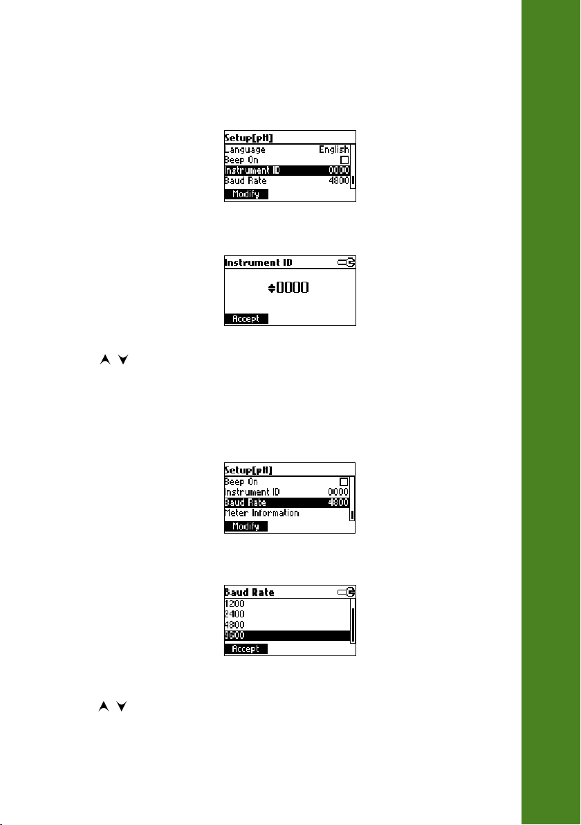
Instrument ID
Highlight Instrument ID.
Press Modify.
Use / keys to change the instrument ID.
Press Accept to confirm or ESC to exit without saving.
Baud Rate
Highlight Baud Rate.
SETUP
Press Modify.
Use / keys to select the desired communication baud.
Press Accept to confirm or ESC to exit.
37
Page 38
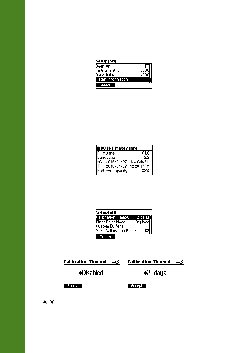
Meter information
Highlight Meter Information.
SETUP
Press Select.
The meter informations are displayed:
‑firmware version
‑language version
‑mV and temperature factory calibration time/date
‑battery capacity
RANGE SPECIFIC PARAMETERS SCREENS
Calibration Timeout
Highlight Calibration Timeout.
38
Press Modify.
Use / keys to set desired value.
Press Accept to confirm or ESC to return without saving.
Page 39
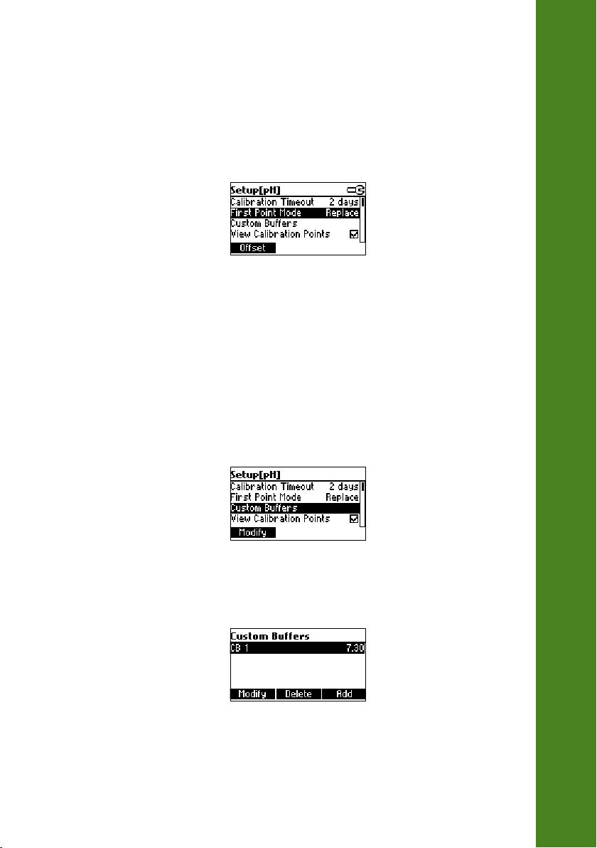
Note: If enabled “CAL DUE” warning will be displayed, the set number of days after
calibration is over passed.
First Point Mode
Highlight First Point Mode.
Press the displayed functional key in order to change the option.
If the Replace option is selected, the slopes between current buffer and nearest lower and higher
buffers will be recalculated.
If the Offset option is selected, an electrode offset correction is performed keeping unchanged the
existing slopes.
Custom Buffers
Highlight Custom Buffers.
Press Modify.
SETUP
Press Delete to delete custom buffer value.
39
Page 40
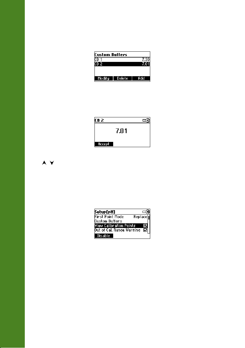
Press Add to add a new buffer to the list (max 5).
SETUP
Press Modify to set custom buffer value.
Use / keys to change the value.
Press Accept to confirm custom buffer value or ESC to exit without saving.
View Calibration Points
Highlight View Calibration Points.
40
Press the displayed functional key to change option.
If option is enabled the calibration buffers corresponding to the last calibration are displayed in the
pH measurement screen.
Page 41

Out of Calibration Range Warning
Highlight Out of Cal.Range Warning.
Press the displayed functional key in order to change option.
If enabled, the “Out Cal Range” message will be displayed if the pH reading is outside. Approxi‑
mately 1 pH unit, from the lowest and highest pH buffer value used for calibration. For single point
pH 7.01 calibration the message will be displayed for pH values less than 4 or greater than 10.
SETUP
41
Page 42
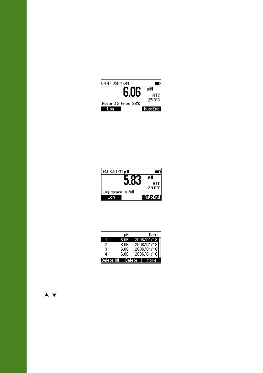
This feature allows the user to log pH measurements. All logged data can be transferred to a PC
through the USB port using HI92000 application.
The maximum logging space is 200 (100 pH and 100 mV range) for HI98168 record locations.
LOGGING
LOGGING THE CURRENT DATA
To store the current reading into memory, press LOG while in measurement mode.
The instrument will display for few seconds the record number and the amount of the free log
space.
If the LOG space is full, the “Log space is full” message will be displayed for few seconds when
LOG key is invoked. Enter View Logged Data Mode and delete records in order to free log space.
VIEW LOGGED DATA
Press RCL to retrieve the information stored while in measurement mode.
42
The list of records is displayed.
If no data were logged, the instrument will display “No Records!” message.
Use / keys to scroll between the records from the list.
Press Delete All to enter Delete All screen.
Press Delete to enter Delete records screen.
Press More to view more information of the focused record.
Page 43
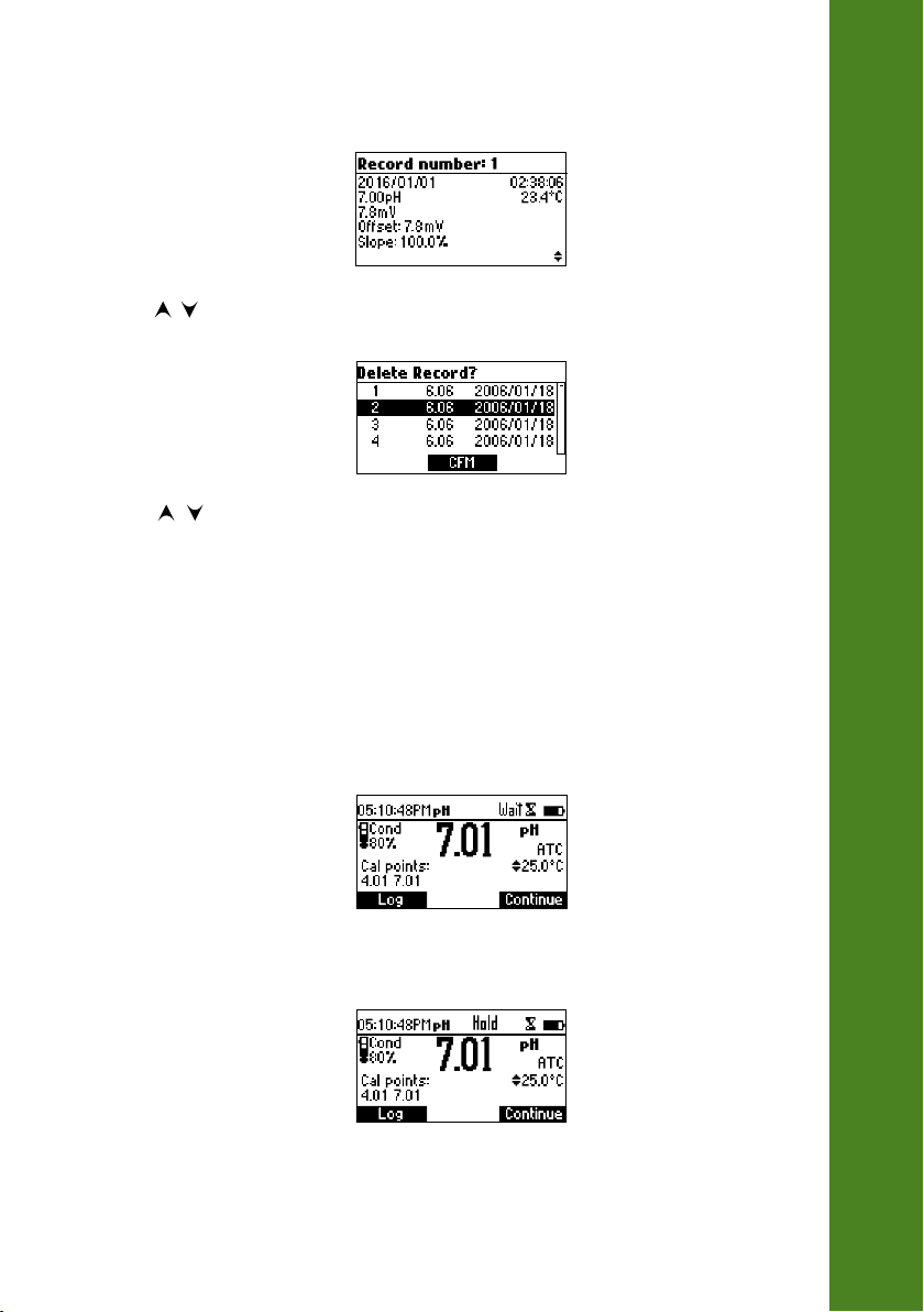
If More is pressed.
Use / keys to scroll between complete log information.
If Delete is pressed.
Use / key to focus the record to be deleted and then press CFM.
Press ESC to exit.
If Delete All is pressed the instrument asks for confirmation.
Press CFM to confirm or ESC to exit without deleting.
LOGGING
To freeze the first stable reading on the LCD press AutoEnd while the instrument is in measurement
mode.
The ”Wait” symbol will blink until the reading is stable.
When the reading is stable, “Hold” icon will be displayed.
Press Continue in order to enter continuous reading mode.
AUTOEND
43
Page 44
IMPORTANT NOTE: For factory calibration contact your local Hanna Instruments Office.
All the instruments are factory calibrated for mV and temperature.
Hanna Instruments’ temperature sensors are interchangeable and no temperature calibration is
needed when they are replaced.
If the temperature is inaccurate, calibration should be performed.
For an accurate recalibration, contact your local Hanna Instruments Office or follow the instructions
below.
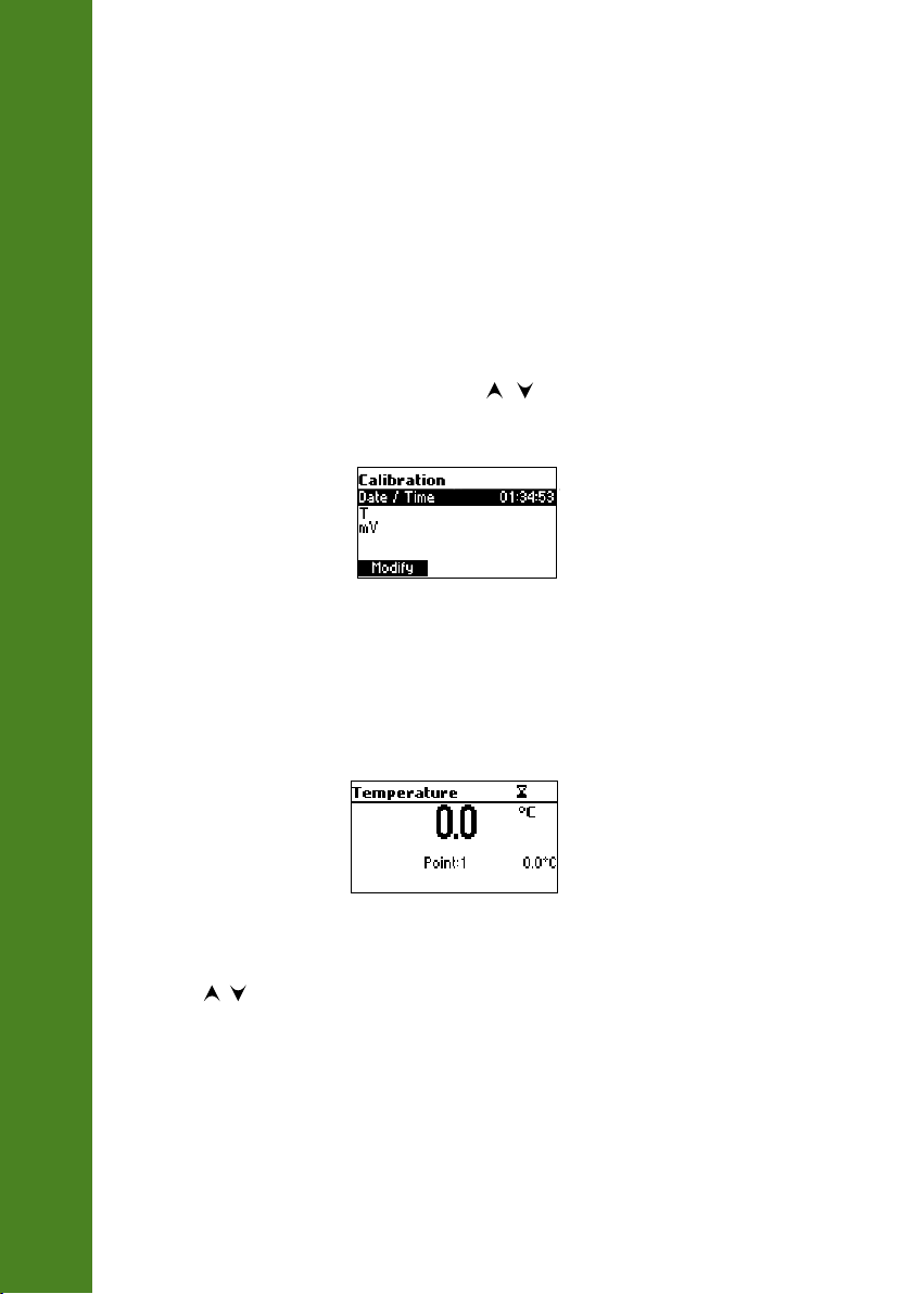
ENTER CALIBRATION MODE
With the instrument off, press and hold down the / then power on the instrument. The
calibration screen is displayed. Highlight “T” and then press Modify to enter in the temperature
calibration mode.
TEMPERATURE CALIBRATION
• Prepare a vessel containing ice and water and another one containing hot water (at approximately
50 °C or 122 °F). Place insulation material around the vessels to minimize temperature changes.
• Use a calibrated thermometer with a resolution of 0.1 °C as a reference thermometer.
TEMPERATURE CALIBRATION (for technical personnel only)
• Immerse the pH probe including temperature sensor into the vessel with ice and water as close
as possible to the reference thermometer. Allow a few seconds for the probe to stabilize.
• Use the / keys to set the calibration point value to that of ice and water mixture, measured
by the reference thermometer. When the reading is stable and within range of the selected
calibration point, the CFM functional key is displayed.
44
Page 45
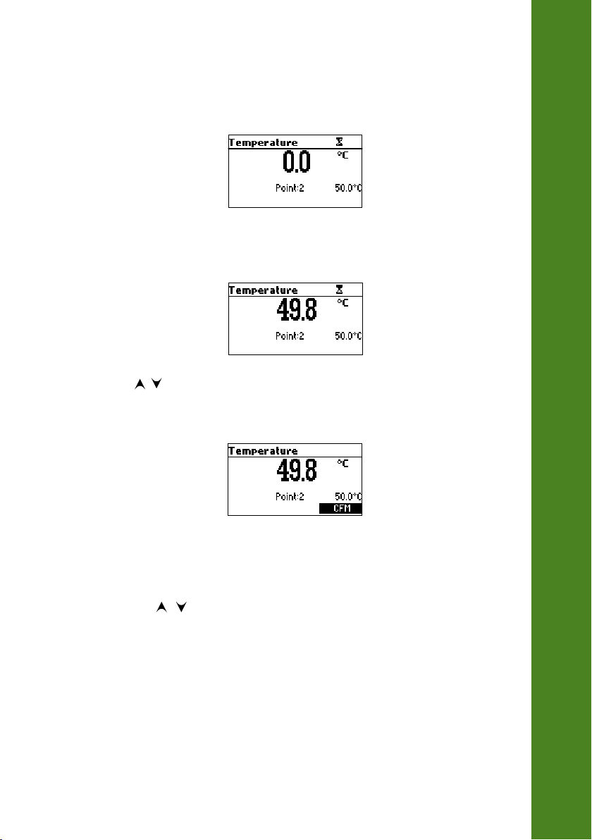
• Press CFM to confirm.
• The second expected calibrated point is displayed.
• Immerse the pH probe including temperature sensor into the second vessel as close as possible
to the reference thermometer. Allow a few seconds for the probe to stabilize.
• Use the / keys to set the calibration point value to that of the hot water.
• When the reading is stable and within range of the selected calibration point, CFM functional key
is displayed.
TEMPERATURE CALIBRATION (for technical personnel only)
• Press CFM to confirm. The instrument returns to measurement mode.
Note: Use / keys to change calibration point if necessary (±10.0 °C) around the
point. If the reading is not within range of the selected calibration point, “Wrong”
message will blink. Change the pH probe including temperature sensor and restart calibration.
45
Page 46

Data transmission from the instrument to the PC can be done with the HI92000 Windows
compatible software (optional). HI92000 also offers graphing and on‑line help feature.
Data can be exported to the most popular spreadsheet programs for further analysis.
To connect your instrument to a PC, use an USB cable connector. Make sure that your instrument is
switched off and plug one connector to the instrument USB socket and the other to the serial or USB
port of your PC.
PC INTERFACE
To allow our users access to the latest version of Hanna Instruments PC compatible software, we
made the products available for download at http://software.hannainst.com. Select the product code
and click Download Now. After download is complete, use the setup.exe file to install the software.
Note: If you are not using Hanna Instruments HI92000 software, please see the following
instructions.
SENDING COMMANDS FROM PC
It is also possible to remotely control the instrument with any terminal program. Use an USB cable
to connect the instrument to a PC, start the terminal program and set the communication options as
follows: 8, N, 1, no flow control.
COMMAND TYPES
To send a command to the instrument follow the next scheme:
<command prefix> <command> <CR>
where: <command prefix> is the 16 ASCII character
<command> is the command code.
®
46
Note: Either small or capital letters can be used.
SIMPLE COMMANDS
KF1 Is equivalent to pressing functional key 1
KF2 Is equivalent to pressing functional key 2
KF3 Is equivalent to pressing functional key 3
RNG Is equivalent to pressing RANGE key
MOD Is equivalent to pressing MODE key
CAL Is equivalent to pressing CAL key
UPC Is equivalent to pressing the UP arrow key
DWC Is equivalent to pressing the DOWN arrow key
RCL Is equivalent to pressing RCL key
SET Is equivalent to pressing SETUP key
CLR Is equivalent to pressing CLR key
Page 47

OFF Is equivalent to pressing OFF key
CHR xx Change the instrument range according with the parameter value (xx):
• xx=00 pH range/0.001 resolution
• xx=01 pH range/0.01 resolution
• xx=02 pH range/0.1 resolution
• xx=03 mV range
The instrument will answer for these commands with:
<STX> <answer> <ETX>
where: <STX> is 02 ASCII code character (start of text)
<ETX> is 03 ASCII code character (end of text)
<answer>:
<ACK> is 06 ASCII code character (recognized command)
<NAK> is 21 ASCII code character (unrecognized command)
<CAN> is 24 ASCII code character (corrupted command)
COMMANDS REQUIRING AN ANSWER
The instrument will answer for these commands with:
<STX> <answer> <checksum> <ETX>
where the checksum is the bytes sum of the answer string sent as 2 ASCII characters.
All the answer messages are with ASCII characters.
RAS Causes the instrument to send a complete set of readings in according with the current
range:
• pH, temperature and mV reading on pH range.
The answer string contains:
• Meter mode (2 chars):
• 00 ‑ pH range (0.001 resolution)
• 01 ‑ pH range (0.01 resolution)
• 02 ‑ pH range (0.1 resolution)
• 03 ‑ mV range
• Meter status (2 chars of status byte): represents a 8 bit hexadecimal
encoding.
• 0x10 ‑ temperature probe is connected
• 0x01 ‑ new GLP data available
• 0x02 ‑ new SETUP parameter
• 0x04 ‑ out of calibration range
• 0x08 ‑ the meter is in autoend point mode
PC INTERFACE
47
Page 48

• Reading status (2 chars): R ‑ in range, O ‑ over range, U ‑ under range. First
character corresponds to the primary reading. Second character corresponds to
mV reading.
• Primary reading (corresponding to the selected range) ‑ 11 ASCII chars, includ‑
ing sign and decimal point and exponent.
PC INTERFACE
MDR Requests the instrument model name and firmware code (16 ASCII chars).
GLP Requests the calibration data record.
• Secondary reading (only when primary reading is not mV) ‑ 7 ASCII chars,
including sign and decimal point.
• Temperature reading ‑ 7 ASCII chars, with sign and two decimal points, always
in °C.
The answer string contains:
• GLP status (1 char): represents a 4 bit hexadecimal encoding.
• 0x01 ‑ pH calibration available
• pH calibration data (if available), which contains:
• the number of calibrated buffers (1 char)
• the offset, with sign and decimal point (7 chars)
• the average of slopes, with sign and decimal point (7 chars)
• the calibration time, yymmddhhmmss (12 chars)
• buffers information (for each buffer)
• type (1 char): 0 ‑ standard, 1 ‑ custom
• status (1 char): N (new) ‑ calibrated in last calibration; O (old) ‑ from
an old calibration.
• warnings during calibration (2 chars): 00 ‑ no warning, 04 ‑ Clean
Electrode warning.
• buffer value, with sign and decimal point and exponent (11 chars).
• calibration time, yymmddhhmmss (12 chars).
• electrode condition, with sign (3 chars). The “‑01” code means not calculated.
48
PAR Requests the setup parameters setting.
The answer string contains:
• Instrument ID (4 chars)
• Calibration Alarm time out for pH (2 chars)
• SETUP information (2 chars): 8 bit hexadecimal encoding.
• 0x01 ‑ beep ON (else OFF)
• 0x04 ‑ degrees Celsius (else degrees Fahrenheit)
• 0x08 ‑ Offset calibration (else Point calibration)
Page 49

• Auto Light Off time (3 chars)
• Auto Power Off time (3 chars)
• The number of custom buffers (1 char)
• The custom buffer values, with sign and decimal point, for each defined custom
buffer (7 chars)
• The short name of the selected language (3 chars)
NSLx Requests the number of logged samples (4 chars).
The command parameter (1 char):
• P ‑ request for pH range
LODPxxx Requests the xxxth pH record logged data.
LODPALL Requests all pH Log on demand.
The answer string for each record contains:
• The logged mode (2 chars):
• 00 ‑ pH range (0.001 resolution)
• 01 ‑ pH range (0.01 resolution)
• 02 ‑ pH range (0.1 resolution)
• 03 ‑ mV range
• Reading status (1 char): R, O, U
• Calculated reading, with sign and decimal point and exponent
(11 chars) ‑ for pH
• Temperature reading, with sign and two decimal points (7 chars)
• mV reading status (1 char): R, O, U
• The mV reading, with sign and decimal point (7 chars)
• The logged time, yymmddhhmmss (12 chars)
• The calibration slope, with sign and decimal point (7 chars)
• The calibration offset, with sign and decimal point (7 chars)
• Temperature probe presence (1 char)
PC INTERFACE
Notes: “Err8” is sent if the instrument is not in measurement mode.
“Err6” is sent if the requested range is not available.
“Err4” is sent if the requested set parameter is not available.
“Err3” is sent if the Log on demand is empty.
“Err9” is sent if the battery power is less than 30%.
Invalid commands will be ignored.
49
Page 50
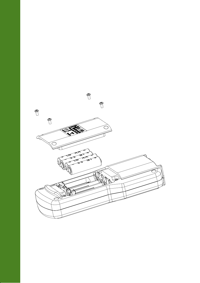
To replace the batteries, follow the next steps:
• Turn OFF the instrument.
• Open the battery compartment by removing the four screws from the back of the instrument.
• Remove the old batteries.
• Insert four new 1.5V AA batteries in the battery compartment while paying attention to the correct
polarity.
• Close the battery compartment using the four screws.
If the battery capacity is less than 20 % the serial communication and the backlight feature are not
available.
BATTERIES REPLACEMENT
HI98168
50
Note: The instrument is provided with the BEPS (Battery Error Prevention System) feature,
which automatically turns the instrument off when the batteries level is too low to ensure
reliable readings.
Page 51
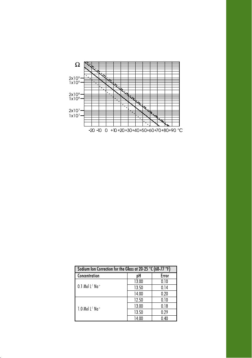
The resistance of glass electrodes partially depends on the temperature. The lower the temperature,
the higher the resistance. It takes more time for the reading to stabilize if the resistance is higher. In
addition, the response time will suffer to a greater degree at temperatures below 25 °C (77 °F).
Since the resistance of the pH electrode is in the range of 50 – 200 MΩ, the current across the
membrane is in the pico Ampere range. Large currents can disturb the calibration of the electrode for
many hours.
For these reasons high humidity environments, short circuits and static discharges are detrimental to
a stable pH reading.
The pH electrode’s life also depends on the temperature. If constantly used at high temperatures, the
electrode life is drastically reduced.
Typical Electrode Life
Ambient Temperature 1 – 3 years
90 °C (194 °F) Less than 4 months
120 °C (248 °F) Less than 1 month
Alkaline Error
High concentrations of sodium ions interfere with readings in alkaline solutions. The pH at which the
interference starts to be significant depends upon the composition of the glass. This interference is
called alkaline error and causes the pH to be underestimated. Hanna Instruments’ glass formulations
have the indicated characteristics.
TEMPERATURE CORRELATION FOR pH SENSITIVE GLASS
51
Page 52
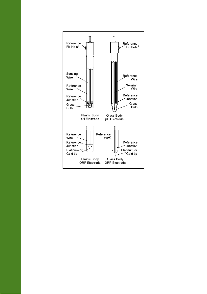
ELECTRODE CONDITIONING AND MAINTENANCE
*Not present in gel electrodes.
PREPARATION PROCEDURE
Remove the electrode protective cap.
DO NOT BE ALARMED IF ANY SALT DEPOSITS ARE PRESENT. This is normal with electrodes and they
will disappear when rinsed with water.
During transport tiny bubbles of air may have formed inside the glass bulb. The electrode cannot
function properly under these conditions. These bubbles can be removed by "shaking down" the
electrode as you would do with a glass thermometer.
If the bulb and/or junction are dry, soak the electrode in HI70300 Storage Solution for at least one
hour.
For refillable electrodes:
If the filling solution (electrolyte) is more than 2½ cm (1”) below the fill hole add HI7071
3.5M KCl + AgCl Electrolyte Solution for single junction electrodes.
52
Page 53

For faster response, unscrew the fill hole screw during measurements.
MEASUREMENT
Rinse the pH electrode tip with distilled water. Immerse the tip (bottom 4 cm /1½” ensuring the
reference junction is submerged) in the sample and stir gently for a few seconds.
For a faster response and to avoid cross‑contamination of the samples, rinse the electrode tip with a
few drops of the solution to be tested, before taking measurements.
STORAGE PROCEDURE
To minimize clogging and assure a quick response time, the glass bulb and the junction of pH
electrode should be kept moist and not allowed to dry out.
Replace the solution in the protective cap with a few drops of HI70300 Storage Solution or, in its
absence, Filling Solution (HI7071 for single junction electrodes). Follow the Preparation Procedure
on page 52 before taking measurements.
Note: NEVER STORE THE ELECTRODE IN DISTILLED OR DEIONIZED WATER.
PERIODIC MAINTENANCE
Inspect the electrode and the cable. The cable used for connection to the instrument must be intact
and there must be no points of broken insulation on the cable or cracks on the electrode stem or bulb.
Connectors must be perfectly clean and dry. If any scratches or cracks are present, replace the elec‑
trode.
Rinse off any salt deposits with water.
ELECTRODE CONDITIONING AND MAINTENANCE
pH Probe Maintenance
For refillable electrodes:
Refill the reference chamber with fresh electrolyte HI7071 for single junction electrodes. Allow the
electrode to stand upright for 1 hour.
Follow the Storage Procedure above.
pH CLEANING PROCEDURE
• General Soak in Hanna Instruments HI7061 General Cleaning Solution for approximately ½ hour.
• Inorganic Soak in Hanna Instruments HI7074 Inorganic Cleaning Solution for 15 minutes.
53
Page 54

Instruction for Application Cleaning Solution
1. Add in a beaker about 50 ‑ 75 mL (or minimum to cover the electrode junction) one of the
following cleaning solution:
• Cleaning solution for inorganic soil deposits (HI70663);
• Cleaning solution for organic soil deposits (HI70664);
2. Soak the electrode for several minutes (5 ‑ 15) while moderately stirring the solution.
3. Remove the electrode from the cleaning solution and rinse it thoroughly with deionized water to
remove all traces of the cleaning solution.
4. After cleaning and rinsing it is preferable to store it in an electrolyte solution for about 1 hour.
5. Rinse the electrode thoroughly with deionized water and measure samples as usual.
Note: If the electrode response is slow or the electrode does not calibrate correctly, repeat the
cleaning procedure.
ELECTRODE CONDITIONING AND MAINTENANCE
54
Page 55

IMPORTANT: After performing any of the cleaning procedures, rinse the electrode thoroughly
with distilled water, refill the reference chamber with fresh electrolyte (not necessary for gel‑filled
electrodes) and soak the electrode in HI70300 Storage Solution for at least 1 hour before taking
measurements.
SYMPTOMS PROBLEM SOLUTION
Slow response/excessive drift. Dirty pH electrode. Soak the electrode tip in HI7061
solution for 30 minutes and then
follow the Cleaning Procedure.
Reading fluctuates up and down (noise). Clogged/dirty junction. Low
electrolyte level (refillable
electrodes only).
Display shows blinking full scale value. Reading out of range. Check that sample is within measur‑
Display shows "Clean electrode"
blinking.
Meter fails to calibrate or gives faulty
readings.
Error messages are displayed during pH
calibration procedure.
Meter shuts off. Dead batteries; Auto‑off feature
"Errxx" message at start up. Internal error. Contact your local Hanna
The instrument does not start when
pressing ON/OFF.
Difference between new and
previous calibration has been
detected.
Broken pH electrode. Replace electrode.
Wrong or contaminated buffer,
electrode dirty or broken.
is enabled: in this case, meter
shuts off after selected period of
non‑use.
Initialization error. Press and hold down ON/OFF for
Clean the electrode. Refill with fresh
electrolyte (refillable electrodes
only).
able range
Clean electrode and recalibrate.
If the problem remains, check the
buffer solutions.
Check that buffer solution is correct
and fresh.
Replace the batteries; Press ON/OFF.
Instruments Office.
about 20 seconds or disconnect and
then connect the batteries.
TROUBLESHOOTING GUIDE
55
Page 56

Electrode Cleaning Solution
Code Description
HI70000P Electrode Rinse Solution, 20 mL sachet, 25 pcs.
HI700601P General purpose cleaning solution for laboratories, 20 mL sachet, 25 pcs.
ACCESSORIES
HI700661P General purpose cleaning solution for agriculture, 20 mL sachet, 25 pcs.
HI700663P Cleaning solution for soil deposits, 20 mL sachet, 25 pcs.
HI700664P Cleaning solution for humus deposits, 20 mL sachet, 25 pcs.
HI70663L Cleaning solution for soil deposits, 500 mL bottle
HI70664L Cleaning solution for humus deposits, 500 mL bottle
HI70061G General Purpose Cleaning Solution, 20 mL sachet, 25 pcs.
HI7061-050 General Purpose Cleaning Solution, 500 mL bottle
HI7074L Inorganic Cleaning Solution, 500 mL bottle
HI7051M Soil Test Solution, 230 mL bottle
56
Page 57

pH Calibration Solution
Code Description
HI50004-01 pH 4.01 Buffer Solution, 20 mL sachet, 10 pcs.
HI50004-02 pH 4.01 Buffer Solution, 20 mL sachet, 25 pcs.
HI50007-01 pH 7.01 Buffer Solution, 20 mL sachet, 10 pcs.
HI50007-02 pH 7.01 Buffer Solution, 20 mL sachet, 25 pcs.
HI50010-01 pH 10.01 Buffer Solution, 20 mL sachet, 10 pcs.
HI50010-02 pH 10.01 Buffer Solution, 20 mL sachet, 25 pcs.
HI5016 pH 1.68 Buffer Solution, 500 mL bottle
HI5004 pH 4.01 Buffer Solution, 500 mL bottle
HI5068 pH 6.86 Buffer Solution, 500 mL bottle
HI5007 pH 7.01 Buffer Solution, 500 mL bottle
HI5091 pH 9.18 Buffer Solution, 500 mL bottle
HI5010 pH 10.01 Buffer Solution, 500 mL bottle
HI5124 pH 12.45 Buffer Solution, 500 mL bottle
HI70004G pH 4.01 Buffer Solution, 20 mL sachet, 25 pcs.
HI70007G pH 7.01 Buffer Solution, 20 mL sachet, 25 pcs.
HI70010P pH 10.01 Buffer Solution, 20 mL sachet, 25 pcs.
HI7004-050 pH 4.01 Buffer Solution, 500 mL bottle
HI7007-050 pH 7.01 Buffer Solution, 500 mL bottle
HI7010-050 pH 10.01 Buffer Solution, 500 mL bottle
Electrode Storage Solution
ACCESSORIES
Code Description
HI70300-050 Storage Solution, 500 mL bottle
HI70300G Storage Solution, 20 mL sachet, 25 pcs.
57
Page 58

Other Accessories
Code Description
HI12923
HI92000
ACCESSORIES
HI920015 USB Cable
HI740157P Electrode refilling pipette
HI720161 Hard carrying case
Glass body, conical tip, refillable pH electrode with internal temperature sensor
PC Software
CERTIFICATION
All Hanna Instruments conform to the CE European Directives.
Disposal of Electrical & Electronic Equipment. The product should not be treated as household
waste. Instead hand it over to the appropriate collection point for the recycling of electrical and
electronic equipment which will conserve natural resources.
Disposal of waste batteries. This product contains batteries, do not dispose of them with other
household waste. Hand them over to the appropriate collection point for recycling.
Ensuring proper product and battery disposal prevents potential negative consequences for the
environment and human health. For more information, contact your city, your local household waste
disposal service, the place of purchase or go to www.hannainst.com.
58
RECOMMENDATIONS FOR USERS
Before using this meter, make sure it is entirely suitable for your specific application and for the
environment in which it is used. Any variation introduced by the user to the supplied equipment may
degrade the meter’s performance. For yours and the meter’s safety do not use or store the meter in
hazardous environments.
MAN98168 06/19
Page 59

Warranty
The HI98168 is warranted for two years against defects in workmanship and materials
when used for their intended purpose and maintained according to instructions.
Electrodes and probes are warranted for six months. This warranty is limited to repair
or replacement free of charge.
Damage due to accidents, misuse, tampering or lack of prescribed maintenance is
not covered.
If service is required, contact your local Hanna Instruments Office. If under warranty,
report the model number, date of purchase, serial number and the nature of the
problem. If the repair is not covered by the warranty, you will be notified of the
charges incurred. If the instrument is to be returned to Hanna Instruments, first obtain
a Returned Goods Authorization (RGA) number from the Technical Service department
and then send it with shipping costs prepaid. When shipping any instrument, make
sure it is properly packed for complete protection.
Hanna Instruments reserves the right to modify the design, construction or appearance of its products
without advance notice.
Page 60

World
Headquarters
Hanna Instruments Inc.
Highland Industrial Park
584 Park East Drive
Woonsocket, RI 02895 USA
www.hannainst.com
MAN98168 Printed in ROMANIA
 Loading...