

Page 1

Instruction Manual
HI 98140 - HI 98150
Portable Waterproof
Microprocessor
Logging GLP
pH / ORP Meters
www.hannainst.com
These Instruments are in
Compliance with the CE Directives
Page 2

Dear Customer,
Thank you for choosing a Hanna Instruments Product.
Please read this instruction manual carefully before using the instru-
ment.
This manual will provide you with all the necessary information for the
correct use of the instrument, as well as a precise idea of its versatility
in a wide range of applications.
These instruments are in compliance with the directives.
TABLE OF CONTENTS
PRELIMINARY EXAMINATION ..................................................................... 3
GENERAL DESCRIPTION ........................................................................... 3
FUNCTIONAL DESCRIPTION .......................................................................5
SPECIFICATIONS ..................................................................................6
INITIAL PREPARATION .............................................................................. 7
SETUP MODE ..................................................................................8
TAKING pH MEASUREMENTS ................................................................. 11
TAKING ORP MEASUREMENTS ............................................................... 12
TAKING TEMPERATURE MEASUREMENTS ................................................ 12
pH CALIBRATION PROCEDURE ............................................................... 13
mV CALIBRATION PROCEDURE .............................................................. 15
TEMPERATURE CALIBRATION PROCEDURE .............................................. 16
LOGGING FUNCTION ............................................................................. 17
GOOD LABORATORY PRACTICE (GLP) ..................................................... 20
LCD BACKLIGHT ............................................................................... 22
DATA TRANSFER TO PC ......................................................................... 22
BATTERY REPLACEMENT ....................................................................... 24
TEMPERATURE-RESISTANCE CORRELATION
FOR HANNA PH SENSITIVE GLASS .......................................................... 25
ELECTRODE CONDITIONING AND MAINTENANCE ...................................... 26
ACCESSORIES ...................................................................................... 28
WARRANTY ......................................................................................... 30
CE DECLARATION OF CONFORMITY ........................................................ 31
2
Page 3

PRELIMINARY EXAMINATION
Remove the instrument from the packing material and examine it
carefully to make sure that no damage has occurred during shipping.
If there is any damage, notify your Dealer.
Each meter is supplied complete with:
• Amplified pH electrode with built-in temperature sensor and
EEPROM and DIN connector
• HI70004 pH 4.01 sachet (1 pc)
• HI70007 pH 7.01 sachet (1 pc)
• Instruction Manual
• AA size Alkaline Batteries (4 pcs)
• Rugged Carrying Case.
Note: Save all packing material until you are sure that the
instrument functions correctly. All defective items must be
returned in their original packaging together with the supplied accessories.
GENERAL DESCRIPTION
HI98140 is a portable logging microprocessor-based pH/temperature
meter, while HI98150 is a portable logging microprocessor-based pH/
ORP/temperature meters.
Both instruments are supplied with an exclusive HANNA (smart)
amplified pH/temperature electrode with DIN connector. The electrode
has an internal memory for storing calibration data.
All pH measurements are automatically compensated for temperature
(ATC). The instrument housing is made of rugged, lightweight material,
making it truly portable.
Five memorized buffers (4.01, 6.86, 7.01, 9.18 and 10.01pH) and
wrong buffer recognition technology make calibration simple and error
free. One or two-point calibration can be performed.
The meters are also equipped with a stability indicator and backlight
feature for comfortable reading even in excessively dark environments.
An user friendly interface provides clear messages regarding errors,
functions and more.
The GLP features provide a guarantee of data consistency.
Measurements can be performed with lab-grade precision in the field as
3
Page 4

well as in the laboratory.
An alarm time-out is available to alert the user if too much time has
elapsed since the last pH calibration and that re-calibration may be
required.
The meter provides a controlled access to calibration and GLP settings
through a password protection method.
The Battery Error Preventing System (BEPS) recognizes batteries levels
as they become weak.
To prolong battery life, the backlight feature is automatically disabled
when the batteries are getting low; a clear indication is displayed on
LCD to warn the user of this condition. However, the meter continues
to measure correctly even when the low battery indication is displayed. The meter automatically switches itself off when the batteries
are too weak to support proper function.
For long term field and lab applications, these meters can be connected
to a 12VDC adapter.
The meters can store measurements in memory at the request of the
user for retrieval at a later time.
HI98140 and HI98150 also allow transfer of data to computer
through the RS232 port.
In addition, the meters allow the user to enter an ID code to uniquely
identify the instruments.
Made of tough, lightweight ABS material, the water-resistant rugged
casing is built to last.
The meters are in compliance with IP67 standards: dust-tight,
protected against the effects of temporary immersion in water and
designed to provide laboratory results and accuracy under harsh
industrial conditions.
4
Page 5

FUNCTIONAL DESCRIPTION
1) Power adapter plug
2) RS232 connector
3) Electrode Connector
4) Liquid Crystal Display (LCD)
5) ON/OFF key, to turn the meter on and off
6) ALT key, to alternate key function
7) RANGE / GLP key, to select measurement ranges, to display time
and date, and to view calibration data (with ALT)
8) CAL / CALT key, to enter calibration mode
9) CFM key, to move down or confirm values (with ALT)
10) LOG / RCL key, to store or recall (with ALT) measurements
11) FNC key, to move up or enter setup mode (with ALT)
12) LIGHT / DEL key, to turn the LCD backlight on and off and to
delete stored data (with ALT)
5
Page 6
SPECIFICATIONS
Range pH -4.00 to 19.99 pH
mV ±600.0 mV (HI98150 only)
±2000 mV autoranging (HI98150 only)
Temp. -20 to 120 °C
Resolution pH 0.01 pH
mV 0.1 mV between ±400mV (HI98150 only)
0.2 mV from +400 to +600mV (HI98150 only)
0.2 mV from -400 to -600mV (HI98150 only)
1 mV outside (HI98150 only)
Temp. 0.1 °C from -10 to 120 °C / 1°C below -10°C
Accuracy pH ±0.01 pH
(@20°C/68°F) mV ±0.2mV between ±400mV (HI98150 only)
±0.4mV from+400 to+600mV (HI98150 only)
±0.4mV from -400 to -600mV (HI98150 only)
±2mV outside (HI98150 only)
Temp. ±0.4 °C from 0 to 70°C / ±1°C outside
Typical EMC pH ±0.02 pH
Deviation mV ±1mV between ±600mV (HI98150 only)
±2 mV outside (HI98150 only)
Temp. ±0.4°C
pH Calibration Automatic 1 or 2 points with 5 memorized
buffers (4.01, 6.86, 7.01, 9.18 and 10.01 pH)
mV Calibration Automatic 2 points at 0, 350 mV or
(HI98150 only) 3 points at 0, 350 and 1900 mV
Temperature
Compensation Automatic from -20 to 120°C
pH Electrode Amplified, with built-in EEPROM and DIN connec-
tor (see accessories)
ORP Electrode Amplified ORP electrode with DIN connector
(HI98150 only; see accessories)
Input Impedance 10
Power supply 4x1.5V AA alkaline batteries/300 hours typical life
Casing IP 67
Environment 0 to 50°C / 100% RH
Dimensions 196 x 80 x 60 mm (7.7 x 3.1 x 2.4")
Weight 500 g (18 oz)
12
Ohm
(with 2700mA/h batteries, without backlight).
12 VDC adapter (HI710005 or HI710006)
6
Page 7

INITIAL PREPARATION
ON/OFF
Each meter is supplied complete with batteries. Remove the back
cover, unwrap the batteries and install them while paying attention
to the polarity. Alternatively, connect the HI 710005 or HI 710006
voltage adapter to the power adapter plug.
To prepare the instrument for use, connect the pH or ORP (HI98150
only) electrode to the connector located on the top of the instrument.
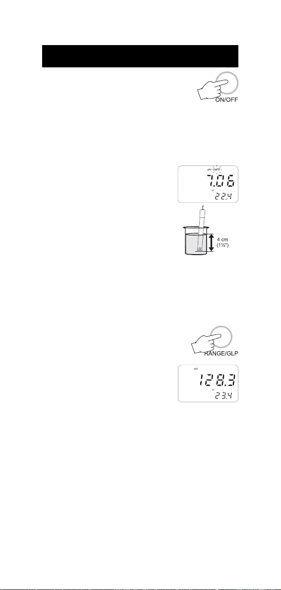
To switch the meter on, press the ON/OFF key.
The batteries charge status or "LINE" message
(if external power adapter is connected) will be
displayed on the LCD for a few seconds.
The meter is now ready to operate.
To maximize battery life, the meter is automatically switched off after 5
minutes of non-use (this feature is enabled by default and can be
disabled through setup code 20). To reactivate the instrument press
the ON/OFF key.
Before proceeding with pH measurements follow the calibration procedure.
Note: When the use of an alternate function (DEL, FNC, CFM, GLP,
RCL and CALT) is requested, press and hold the ALT key first
and then the second listed key.
Note: to prevent damage to the electrode, remove it from the sample
before turning the meter off.
If the meter is OFF, detach the electrode from the meter before
immersing it in the storage solution.
7
Page 8

SETUP MODE
Setup can be used to view data regarding instrument status (e.g.
battery charge) or to change the meter parameters (e.g. time).
• To enter this mode press the ALT and
FNC keys when the meter is in measurement mode.
• The setup code "00" will blink on the
lower LCD and "Set" will be displayed on
the upper one.
• Select the code of the desired
parameter using the or
key.
• Press ALT and CFM to confirm the
code.
Note: If ALT and FNC are pressed before code confirmation, the meter
will default to measurement mode.
• If the selected parameter is password protected, the lower LCD will
display "PAS" and the password must be entered to proceed.
Otherwise, the current parameter value will be displayed.
PASSWORD PROTECTION
Setting of time, date and calibration alarm time-out are password
protected and the user will be asked to enter the password to change
these parameters. After code confirmation the upper LCD will display
"0000".
• If password is set to 0000 (factory setting), just press ALT and
CFM to confirm.
• If password is set to a value different from 0000, enter the
password with the up and down arrow keys and then press ALT
and CFM to confirm.
• If password is incorrect the meter displays the "WRONG" indication
and asks for the password again.
• If password is correct, the meter provides access to the parameter.
8
Page 9

PARAMETER SETTINGS
• Once the parameter code (and password
if needed) has been entered, the current
value of the selected parameter on the
upper LCD and the parameter code on
the lower LCD will be displayed. The parameter or a part of it will
blink (e.g. only the hour blinks if time has been selected).
• Enter the new value using the arrow keys.
• If there is another part of the parameter to be set (e.g. minutes
for the time), press RANGE to gain access and then enter the new
value using the arrow keys.
• Press ALT and CFM to confirm the value.
• If the entered value is not acceptable, the "WRONG" indication
will be displayed for a few seconds and then the meter will ask for
a correct value.
• If the confirmed value is accepted, the meter will pass to the next
parameter (asking for the password if it is protected).
Note: If ALT and FNC are pressed before parameter value confirma-
tion, the meter will not update the parameter and after
escaping will ask for a new setup code.
The following table lists the setup codes along with the description of
the specific setup items, their valid values and the factory settings
(default):
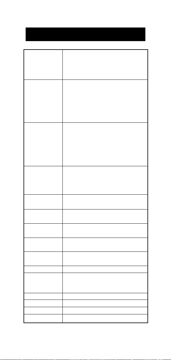
Code Valid values Default
00 Instrument ID code 0000÷9999 0000
01 Current time
02 Current date
03 Current year
10 Calibration alarm time-out 01÷99 days , OFF OFF
20 Auto-Off/Power down time-out ON, OFF ON
21 Firmware version
22 Battery level test
99 Password
1
1
1
2
hh:mm 00:00
dd:mm 01:01
YYYY 1998
0000÷9999 0000
9
Page 10

1
The meter automatically checks for entered time/date accuracy as follows:
0≤hh≤23; 0≤mm≤59; 01≤dd≤28/29/30/31; 1≤MM≤12; 1998≤YYYY≤2097.
2
To change the password, the correct code must be entered first. If the password
has been forgotten, the password protected features are no longer accessible;
in this case contact your nearest Hanna Service Center.
Some of the setup parameters are explained below.
Code 00 - Setting the identification (ID) code
When using several identical meters it may be useful to uniquely
identify them by assigning an ID code to each meter.
• Select code 00.
• Enter a 4-digit value using the arrow keys.
• Press ALT and CFM to confirm the value.
Code 20 - Auto-off
The auto-off timeout is fixed at 5 minutes.
• Select code 20 to enable/disable this feature.
Code 22 - Battery level test
• Select code 22.
• If the meter is connected to an external power adapter, the LCD
will display "LINE" otherwise it will display "bAtt" on the upper
display, and the remaining percentage
of battery charge (100% means fully
charged battery and 0% corresponds to
the minimum battery voltage that allows
the meter to operate).
Note: the battery level test is also performed any time the meter is
turned on.
10
Page 11
TAKING pH MEASUREMENTS
Connect the pH electrode with the built-in temperature sensor to the meter and press ON/OFF to
power on the instrument. The meter automatically
checks that the stored calibration data correspond to the connected
electrode. The pH range will be automatically set.
If the pH electrode is not connected the LCD will display the "no
probe" message and then dashed lines in place of the readings.
For greatest accuracy, it is recommended to set
the Calibration alarm time-out to the value
appropriate to your specific use and calibrate
the meter as soon as the "DATE" warning
symbol blinks on LCD (see GLP section).
To take pH measurements, simply submerge
the bottom 4 cm (1½") of the electrode in
the solution to be tested and stir gently.
Allow for the reading to stabilize.
The temperature is displayed in the lower LCD.
The pH reading is automatically temperature compensated (ATC).
If the meter displays "----" it means that the reading is out of range.
A blinking reading means that the electrode is "dead".
By continuously pressing the RANGE key the
following information will be displayed on
the upper LCD:
• mV reading (HI98150 only)
The mV scale is autoranging, when the
reading is outside ±600mV the decimal
point automatically disappears.
• Time
• Day - Month
• Year
Pressing RANGE again, the meter returns to pH reading.
Note: When date or time is displayed, it is possible to change them
pressing ALT and FNC with no need to enter setup mode.
Note: If measurements are taken successively in different samples, it
is recommended to rinse the electrode thoroughly with deionized water or, if not available, tap water first and then with
some of the next sample to condition the electrode before
immersing it in the sample.
11
Page 12

TAKING ORP MEASUREMENTS
(HI98150 ONLY)
Connect the ORP electrode to the meter and press the ON/OFF key.
The meter automatically sets the mV range.
If the ORP electrode is not connected the LCD will display the "no
probe" message and then dashed lines in place of the readings.
To take ORP measurements, simply submerge the bottom 4 cm (1½")
of the ORP electrode in the solution to be tested, stir gently and allow
for the reading to stabilize.
Note: The ORP electrodes are not provided with the temperature
sensor.
By continuously pressing the RANGE key the following information will
be displayed on the upper LCD:
• Time
• Day - Month
• Year
Pressing RANGE again, the meter returns to mV reading.
Note: If measurements are taken successively in different samples, it
is recommended to rinse the electrode thoroughly with deionized water or if not available tap water first and then with
some of the next sample to condition the electrode before
immersing it in the sample to be tested.
TAKING TEMPERATURE MEASUREMENTS
The temperature sensor is integrated in the pH electrode.
Immerse the pH electrode in the solution (allow a few minutes for the
temperature to stabilize) and press the ON/OFF key. The temperature
is displayed in the lower LCD.
Note: If temperature measurement is out of range the LCD will
display " - - -".
12
Page 13

pH CALIBRATION PROCEDURE
For greatest accuracy, it is recommended that the instrument is
calibrated frequently. For a faster procedure, it is possible to calibrate
at 1 point, but it is always a good practice to calibrate at 2 points.
A two-point calibration can use any combination of the three sets:
(4.01) (6.86 / 7.01) (9.18 / 10.01)
Only one value from each set can be selected. For example if pH
7.01 is used as first point, it will not be possible to select pH 6.86
as the second point.
In the case of a two-point calibration (in the acidic range) from 0 to
7 pH, use pH buffer 7.01 (or 6.86) as the first solution and pH buffer
4.01 as the second solution. if testing in the alkaline range from 7 to
14 pH, use pH buffer 10.01 (or 9.18) as the second solution.
Due to electrode conditioning time, the electrode must be kept
immersed a few seconds to stabilize. The meter is equipped with a
stability indicator and the user will be guided step by step with easy
indications on the LCD during the calibration. This will make the
calibration a simple and error-free procedure.
pH CALIBRATION
1. Rinse the electrode with a portion of the
first calibration buffer or clean water.
Dip the bottom 4 cm (1½") of the
electrode into a beaker containing the
solution.
2. Press CAL when the meter displays pH
measurement.
3. Enter the password (if different from "0000") with the arrow keys.
4. Press ALT and CFM to confirm the password or CAL to exit.
5. If password is correct, the meter displays "7.01pH" on the lower
LCD with the "BUF 1" and "CAL" indication. The upper LCD shows
the uncalibrated pH reading.
13
Page 14

Note: The buffer pH value, and thus the value displayed on the
lower LCD, varies with temperature. For example, at 20oC it
shows 4.00 -7.03 -10.06, at 25oC it shows 4.01-7.01-10.01.
6. Select the first buffer solution value with and if necessary.
7. When the "CFM" symbol blinks, the reading is stable and calibration can be
confirmed.
8. Press ALT and CFM to confirm the first buffer.
9. If everything is satisfactory the LCD will
display "Stor" and then the second buffer
value expected will be displayed (twopoint calibration). If a wrong solution or
electrode has been used or if the buffer is
polluted, "WRONG" will be displayed to
alert the user.
10. If only a single point calibration is required, press CAL to exit the calibration
mode and maintain the previous slope
calibration. The instrument then checks
the electrode parameters and advises user
of abnormalities by "old probe" and "dead
probe" indications.
11. Press or to select the second buffer value. The meter will
display the "BUF 2" indication.
12. Rinse the electrode with some of the second buffer solution or clean
water.
13. Dip the bottom 4 cm (1½") of the pH electrode in a beaker
containing the second buffer.
14. When the "CFM" symbol blinks, press ALT
and CFM to confirm the second calibration point.
14
Page 15
15. The LCD will display "Stor". The instrument checks the electrode
parameters and advises the user of abnormalities by "old probe"
and "dead probe" indications (in these cases, repeat the calibration with fresh buffers). If everything is satisfactory the meter is
calibrated and it returns to normal operational mode.
CALIBRATION ERROR MESSAGES
If the "old probe", "dead probe" or "WRONG" messages are displayed
during calibration, check your electrode by following the conditioning
and maintenance procedures and repeat calibration. The pH electrode might have to be replaced if calibration cannot be successfully
performed.
note: see "GLP" paragraph for more details about "old probe" and
"dead probe" messages.
mV CALIBRATION PROCEDURE
(HI98150 ONLY)
A two or three-point calibration can be performed. The first two
calibration points are always 0 and +350 mV; the third point is
optional at +1900 mV.
1. Connect a mV simulator (HI8427 or HI931001 with the proper
connecting cable) to the meter and set it to 0 mV.
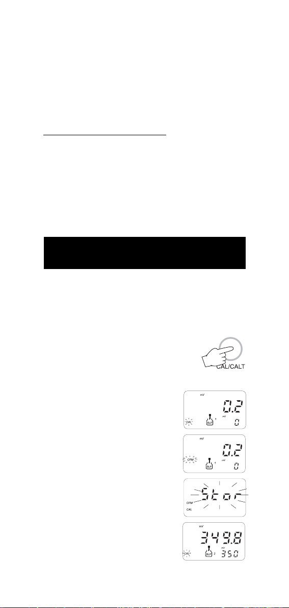
2. Press CAL when LCD is displaying mV.
3. Enter the password (if different from "0000")
with the arrow keys.
4. Press ALT and CFM to confirm the password or CAL to exit.
5. If password is correct, the meter will
display "0 mV" on the lower LCD with the
"BUF 1" and "CAL" indication. The upper
LCD displays the mV reading.
6. When the "CFM" symbol blinks, the reading is stable and calibration can be
confirmed.
7. Press ALT and CFM to confirm the first
value.
8. The LCD will display "Stor" for a few
seconds.
9. The meter will then display "350 mV" on
the lower LCD with the "BUF 2" indication.
15
Page 16

10. Set the simulator to +350 mV.
11. When the "CFM" symbol blinks, the reading is stable. Press ALT and CFM to
confirm the second value.
12. The LCD will display "Stor" for a few seconds.
13.If only a two-point calibration is required, press CAL to leave the
calibration mode. Proceed with the next step for three-point
calibration.
14. The meter will display "1900 mV" on the
lower LCD with the "BUF 3" indication.
15. Set the simulator to 1900 mV.
16. When the "CFM" symbol blinks, the reading is stable. Press ALT and CFM to
confirm the third value.
17. Calibration is now complete, the instrument returns to normal
operational mode.
Note: "WRONG" message notifies the user if the selected value is
wrong.
TEMPERATURE CALIBRATION PROCEDURE
(for technical personnel only)
A two point calibration at 0.0, 50.0°C has to be performed in order
to store the new calibration data in memory.
1. Immerse the pH electrode with the built-in temperature sensor in
the 0°C temperature bath.
2. Press ALT and CALT to enter temperature calibration mode.
3. Enter the password.
4. The meter will display "0.0 °C" on the lower LCD with the "BUF 1"
and "CAL" indication.
5. When the reading is stable the "CFM" symbol starts to blink.
6. Press ALT and CFM to confirm. LCD will then display 50.0°C on
the lower LCD with the "BUF 2" indication.
7. Immerse the pH electrode with the built-in temperature sensor in
the 50°C temperature bath.
8. When the reading is stable the "CFM" symbol starts to blink.
9. Press ALT and CFM to confirm and return to normal operational
mode.
16
Page 17
LOGGING FUNCTION
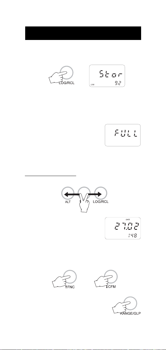
To store the current reading in memory press the LOG key while in
measurement mode. The LCD will display "Stor" along with the "LOG"
indication and the sample number for a few seconds.
By pressing the LOG key a complete set of information is memorized:
date, time, pH and mV (HI98150 only) readings, temperature
reading and also a message on the meter status.
Up to 500 samples can be stored into memory.
When the memory is full and the LOG key is
pressed, the sample will not be stored and
the LCD will display "FULL". In this case it is
necessary to delete all the memory to proceed.
TO VIEW LOGGED DATA
To retrieve the memorized information press ALT and RCL.
The meter displays the date (upper LCD) and
the number (lower LCD) of the last logged
sample. The "ZERO" indication will be displayed if no samples are stored in memory.
• Select the desired sample number with the arrow keys. Pressing
the key while the last sample is displayed causes the meter to
go to the first sample.
• Press RANGE to view remaining data of the
selected sample. After the date information,
the remaining data will be displayed in the
following order:
17
Page 18
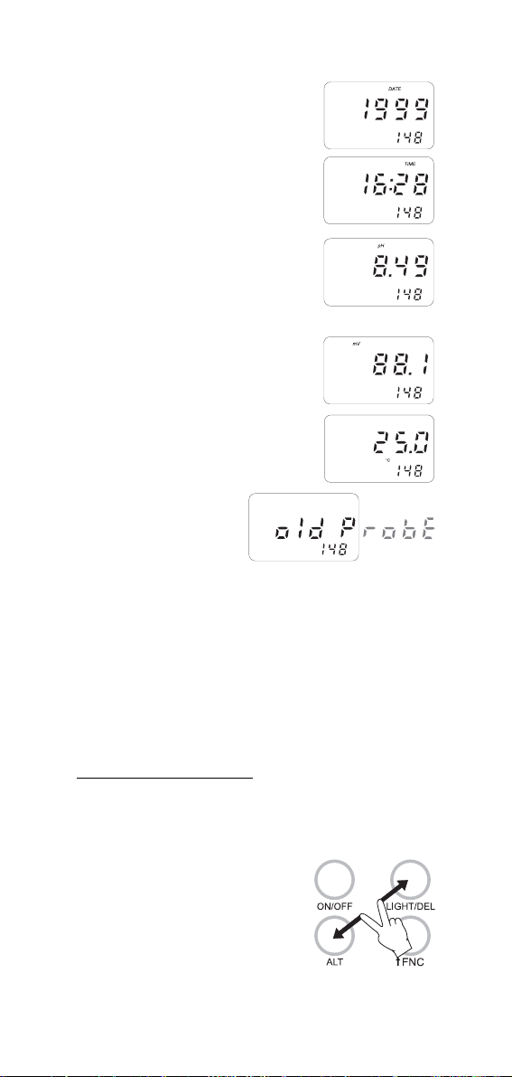
- year
- time
- pH reading
"----" means reading out of range or
no probe was connected.
"OrP" means that an ORP electrode
was connected.
- mV reading
(HI98150 only)
"----" means reading out of range.
- temperature reading
"----" means reading out of range.
- GLP message
• If RANGE is pressed when the GLP message is displayed, the LCD
will revert to the date of the viewed sample.
• It is always possible to skip to another sample using the up and
down arrow keys. For example, if the pH reading of a sample is
displayed, pressing the up arrow key will cause the meter to
display the pH reading of the next sample.
• At any time it is possible to return to normal operational mode by
pressing ALT and RCL.
TO DELETE LOGGED DATA
It is possible to delete a single sample or all the memory at one time.
To delete a single sample:
• Enter the viewing logged data mode and select the desired
sample number.
• Press ALT and DEL. The "CFM" indication
will start blinking asking for confirmation.
• Press the ALT and CFM to confirm deletion.
18
Page 19

Note: Press ALT and DEL. to escape without data deletion.
When viewing through the logged data, the "NUL" message will be
displayed when selecting a deleted sample.
To delete all data in memory:
• Press ALT and DEL while in normal operational mode. The "del All" message will
scroll on the LCD and the "CFM" indication
will start blinking asking for confirmation.
• Press ALT and CFM to confirm deletion.
Note: Press ALT and DEL to escape without data deletion.
Note: If no samples are stored in memory and a deletion is
attempted, the meter will show the message "Zero" and then
returns to normal operational mode.
19
Page 20

GOOD LABORATORY PRACTICE (GLP)
GLP is a set of functions that allows the storage or retrieval (when
necessary) of data regarding the maintenance and status of the
electrode. HI98140 and HI98150 use electrodes with a built-in
EEPROM in which calibration data are read at start-up and stored
after calibration. The meter can automatically analyze the data and
advise the user if a problem is found with a clear message.
PROBE LIFE VERIFICATION
At the end of calibration, the meter checks if offset is between -30 and
+30 mV and the slope between 53.5 and 62 mV/pH. If the values
are not within these parameters, the message "old probe" scrolls across
the LCD. The electrode is still working, but it will be necessary to perform
a cleaning procedure (see electrode cleaning and maintenance paragraph) or replace it.
If the offset is outside the -60 and +60 mV range or the slope is
outside the 40 to 70 mV/pH interval, the "dead probe" message will
scroll across the LCD; the readings will blink on the upper LCD to warn
the user that they are not reliable.
ELECTRODE IDENTIFICATION
At start-up the meter checks if the electrode is inserted. If not the
message "no probe" scrolls across the LCD and a dashed line "----" will
be displayed in place of the reading.
If the meter detects a "dead probe" the readings will blink.
The meter checks the electrode only at start up. If an electrode
replacement is needed, turn the meter off before disconnecting the
electrode. Then replace the electrode and turn the meter on again.
CALIBRATION ALARM TIME-OUT
The calibration alarm time-out is available only for pH calibration.
It is possible to set (through setup code 10) the number of days
before the next required calibration procedure. User can set a value
from 01 to 99 days. The default value is 07. Set the parameter to
"OFF" to disable this feature.
When turned on, the meter checks if the timeout time has expired. If the time has run out,
the message "Cal date" scrolls across the LCD.
The "DATE" symbol will blink as a reminder.
Alarm time-out is also signaled when viewing logged data through
the "Cal date" message.
20
Page 21

GLP AND RS232
All the GLP data can be retrieved (if the electrode is connected) from
a PC through the RS232 communication feature. The calibration data
are transferred to the PC along with measurement data (see "Data
transfer to PC" paragraph).
LAST CALIBRATION DATA
Last calibration data are stored automatically after a successful
calibration and they can be displayed by pressing the GLP key.
to view pH calibration data
• Press ALT and GLP when the meter displays pH reading.
• The LCD will then display the last pH calibration date.
• Press RANGE to scan remaining data, in the following order:
last calibration time
electrode offset value in mV ("OFF" appears in the lower LCD)
electrode slope in mV/pH ("SLP" appears in the lower LCD)
first point calibration buffer
second point calibration buffer (only if a 2-point calibration has
been performed).
If calibration was performed with an old or dead probe, the
message "Old probe" or "Dead probe" will scroll on LCD.
• The meter will then return to normal operational mode. Press ALT
and GLP to escape before viewing all the data.
to view mV calibration data (HI98150 only)
• Press ALT and GLP when the meter displays mV reading.
• The LCD will then display the last mV calibration date.
• Press RANGE to scan remaining data, in the following order:
last calibration time
first calibration point
second calibration point
third calibration point (only if a 3-point calibration has been
performed).
• The meter will then return to normal operational mode. Press ALT
and GLP to escape before viewing all the data.
21
Page 22

LCD BACKLIGHT
The LCD can be illuminated to allow the user to see the readings even
in dark environments.
It can be enabled/disabled through the LIGHT
key and it is automatically disabled when batteries are in low battery condition.
Two levels (low and high) of backlighting can be selected. Repeatedly
pressing the LIGHT key causes the lighting to cycle from off to low then
to high intensity.
Note: It is not possible to enable backlight in low battery condition;
the "Batt" indication will be displayed when trying to do so.
When the backlight is enabled and an external power supply
is connected to the instrument, the backlight is always on.
DATA TRANSFER TO PC
Press RANGE to set the meter to time or date mode and connect the
meter to a PC through the RS232C output (the connector is located
on the top of the meter). Use HI920011 (5 to 9-pin) connection
cable.
To stop communication, press RANGE to display pH or mV reading.
SPECIFICATIONS:
Isolated 8-bit data transmission
Baud Rate: 2400
Start bit: 1
Stop bit: 1
Parity bit: none
SENDING COMMANDS FROM PC
With any terminal programs it is possible to remotely control your pH
meter. Connect the meter to the PC through the HI920011 cable,
start the terminal program and set the communication options as
follows: 8, N, 1, no flow control.
To send a command to the pH meter the scheme is:
<command> <CR>
The computer sends the command expressed as a 3-character sequence and a CR character.
Note: All the terminal programs that support the ANSI escape
sequence, represent the CR character with the string '^M'.
22
Page 23

The commands available are as follows:
MOD - to request the firmware code of the meter.
GLP - to request the last calibration data.
The meter answers with the following order:
pH calibration status (0=not calibrated , 1=calibrated)
pH calibration date (ddmmyy)
pH calibration time (hhmm)
pH electrode offset
pH electrode slope
pH buffer 1
pH buffer 2
mV calibration status (HI98150 only;1=calibrated,0=not calibr.)
mV calibration date (ddmmyy; HI98150 only)
mV calibration time (hhmm; HI98150 only)
mV buffer 1 (HI98150 only)
mV buffer 2 (HI98150 only)
mV buffer 3 (HI98150 only)
If an item is not available (e.g. buf 3 in case of a two points
mV calibration) the character "N" will be received.
PAR - to request the setup parameters setting.
The meter answers with a 6-character string for each parameter.
LTB - to request the number of logged samples.
LOD - to request the logged data.
The meter answers with the following order:
status byte
date (ddmmyy)
time (hhmm)
pH reading (binary)
mV reading (binary; HI98150 only)
temperature reading (binary)
At the end of the logged data the checksum (2 complement)
is sent.
Note: The meter will send <CAN> if a corrupted or unknown
command is received.
These commands may be sent with either capital or small letters.
Invalid commands will be ignored. The characters sent by the pH
meter are always capital letters.
23
Page 24

-
BATTERY REPLACEMENT
When the batteries are inserted and no power adapter is connected,
the meter can recognize different batteries charge levels.
1. Fully charged batteries - The backlight can be enabled.
2. Weakening batteries - The backlight is automatically disabled
and it is not possible to enable it until new batteries are inserted
or an external power adapter is connected. The "Batt" indication
appears when trying to enable backlight.
3. Weak batteries - "Bat" indication is displayed on lower LCD
alternating the temperature reading. Backlight is disabled and
meter can work for about 10 hours.
4. Dead batteries - LCD shuts off. The instrument stops working to
avoid erroneous readings.
Battery replacement must only take place
in a non hazardous area using 1.5V
alkaline AA type batteries.
In order to replace run down batteries,
simply remove the two screws on the rear
cover of the instrument and replace the
four 1.5V AA batteries with new ones,
paying attention to the correct polarity.
A 12VDC power adapter can also be used
to power the unit (see accessories).
Note: The instrument uses the following configuration.
+
It is recommendable to purchase the Hanna HI710005 and HI710006
voltage adapters that use the proper polarity configuration.
However, HI 98140 and HI 98150 can be used with other adapters.
In this case, remember to check the correct polarity of your adapter
before connecting it to the meter.
24
Page 25

TEMPERATURE-RESISTANCE CORRELATION FOR
0
0+10+20+30+40+50+60+70+80+90
C
HANNA pH SENSITIVE GLASS
The resistance of glass electrodes partially depends on the temperature.
The lower the temperature, the higher the resistance. It takes longer time
for the reading to stabilize if the resistance is higher. In addition, the
response time will suffer to a greater degree at temperatures below 10°C.
Ω
Ω
9
2x10
-10
9
1x10
-10
8
-10
2x10
8
1x10
-10
7
2x10
-10
-10
7
1x10
-10
-20-2
-20 -10 0 +10 +20+30+40 +50 +60 +70 +80 +90 °C
°
Since the resistance of the pH electrode is in the range of 200 Mohm,
the current across the membrane is in the pico Ampere range. Large
currents can disturb the calibration of the electrode for many hours.
For these reasons high humidity environments, short circuits and
static discharges are detrimental to a stable pH reading.
The pH electrode's life also depends on the temperature. If constantly
used at high temperatures, the electrode life is drastically reduced.
Typical Electrode Life
Ambient Temperature 1- 3 years
90 °C Less than 4 months
120°C Less than 1 month
High concentrations of sodium ions interfere with readings in alkaline
solutions; the pH at which the interference starts to be significant
depends upon the composition of the glass. This interference is the
alkaline error and causes the pH to be underestimated. Hanna's
glass formulations have the indicated characteristics.
Alkaline Error
Sodium Ion Correction for the Glass at 20-25°C
Concentration pH Error
0.1 Mol L-1 Na
1.0 Mol L-1 Na
+
+
13.00
13.50
14.00
12.50
13.00
13.50
14.00
0.10
0.14
0.20
0.10
0.18
0.29
0.40
25
Page 26

ELECTRODE CONDITIONING
AND MAINTENANCE
Note: to prevent damage to the electrode, remove the pH electrode
from the sample before turning the meter off.
If the meter is OFF, detach the electrode from the meter before
immersing the electrode in the storage solution.
PREPARATION
Remove the protective cap.
DO NOT BE ALARMED IF SALT DEPOSITS ARE PRESENT.
This is normal with electrodes and they will disappear when rinsed
with water.
During transport tiny bubbles of air may form inside the glass bulb.
The electrode cannot function properly under these conditions. These
bubbles can be removed by "shaking down" the electrode as you
would do with a glass thermometer.
If the bulb and/or junction are dry, soak the electrode in HI70300
Storage Solution for at least one hour.
For refillable electrodes:
If the fill solution (electrolyte) is less than 1 cm (½") below the fill
hole, add HI7082 3,5M KCl Electrolyte Solution for double
junction or HI7071 3,5M KCl+AgCl Electrolyte Solution for single
junction electrodes.
For a faster response unscrew the fill hole screw during measurements.
For AmpHel electrodes:
If the electrode does not respond to pH changes, the battery is run
down and the electrode should be replaced.
MEASUREMENT
Rinse the electrode tip with distilled water.
Immerse the tip (4 cm /1½") in the sample and stir gently for
approx. 30 seconds.
For a faster response and to avoid cross contamination of the samples,
rinse the electrode tip with a few drops of the solution to be tested,
before taking measurements.
STORAGE
To minimize clogging and ensure a quick response time, the glass
bulb and the junction should be kept moist and not allowed to dry
out.
26
Page 27

Replace solution in the protective cap with a few drops of HI70300 or
HI80300 Storage Solution or, in its absence, Filling Solution
(HI7071 for single junction or HI7082 for double junction electrodes).
Follow the Preparation Procedure above before taking measurements.
Note: NEVER STORE THE ELECTRODE IN DISTILLED WATER OR DRY.
PERIODIC MAINTENANCE
Inspect the electrode and the cable. The cable used for connection to
the meter must be intact and there must be no points of broken
insulation on the cable or cracks on the electrode stem or bulb.
Connectors must be perfectly clean and dry.
If any scratches or cracks are present, replace the electrode.
Rinse off any salt deposits with water.
For refillable electrodes:
Refill it with fresh electrolyte (HI7071 for single junction or HI7082 for
double junction electrodes). Allow the electrode to stand upright for 1
hour.
Follow the Storage Procedure above.
CLEANING PROCEDURE
General Soak in Hanna HI7061 General Cleaning Solution for
approximately 1 hour.
Removal of films, dirt or deposits on the membrane/junction:
- Protein Soak in Hanna HI7073 Protein Cleaning Solu-
tion for 15 minutes.
- Inorganic Soak in Hanna HI7074 Inorganic Cleaning
Solution for 15 minutes.
- Oil/grease Rinse with Hanna HI7077 Oil and Fat Clean-
ing Solution.
IMPORTANT: After performing any of the cleaning procedures rinse
the electrode thoroughly with distilled water, drain and refill the
reference chamber with fresh electrolyte, (not necessary for GEL filled
electrodes) and soak the electrode in HI70300 Storage Solution for
at least 1 hour before taking measurements.
TROUBLESHOOTING
Evaluate your electrode performance based on the following possibilities.
• Noise (Readings fluctuate up and down) could be due to:
- Clogged/Dirty Junction: Refer to the Cleaning Procedure above.
- Loss of shielding due to low electrolyte level (in refillable
27
Page 28

electrodes only): refill with fresh HI7071 for single junction or
HI7082 for double junction electrodes.
• Dry Membrane/Junction: Soak in Storage Solution HI70300
for at least 1 hour.
• Drifting: Soak the electrode tip in warm Hanna Solution
HI7082 for one hour then flush tip with distilled water. Refill with
fresh HI7071 for single junction electrodes and HI7082 for double
junction electrodes.
• Low Slope: Refer to the cleaning procedure above.
• No Slope: Check the electrode for cracks in glass stem or bulb
and replace the electrode.
• Slow Response/Excessive Drift: Soak the tip in Hanna Solution HI7061 for 30 minutes, rinse thoroughly in distilled water
and then follow the Cleaning Procedure above.
ACCESSORIES
pH CALIBRATION SOLUTIONS
HI 70004P pH 4.01 Buffer Sachets, 20mL, 25 pcs
HI 70007P pH 7.01 Buffer Sachets, 20mL, 25 pcs
HI 70010P pH 10.01 Buffer Sachets, 20mL, 25 pcs
HI 7004L pH 4.01 Buffer Solution, 460 mL
HI 7006L pH 6.86 Buffer Solution, 460 mL
HI 7007L pH 7.01 Buffer Solution, 460 mL
HI 7009L pH 9.18 Buffer Solution, 460 mL
HI 7010L pH 10.01 Buffer Sol., 460 mL
ELECTRODE STORAGE SOLUTION
HI 70300L Storage Solution, 460 mL
ELECTRODE CLEANING SOLUTIONS
HI 70000P Electrode Cleaning Sachets, 20 mL, 25 pcs
HI 7061L General Cleaning Sol., 460 mL
HI 7073L Protein Cleaning Sol., 460mL
HI 7074L Inorganic Cleaning Sol., 460mL
HI 7077L Oil & Fat Cleaning Sol.,460 mL
REFILL ELECTROLYTE SOLUTIONS
HI 7071 3.5M KCl + AgCl Electrolyte, 4x50 mL
HI 7072 1M KNO3 Electrolyte, 4x50 mL
HI 7082 3.5M KCl Electrolyte, 4x50 mL, for double junction electrodes
28
Page 29

ORP PRETREATMENT SOLUTIONS
HI 7091L Reducing Pretreatment Solution, 460 mL
HI 7092L Oxidizing Pretreatment Solution, 460 mL
SMART ELECTRODES
HI1615D combination pH electrode, glass-body, single junction,
refillable with built-in temperature NTC sensor and
EEPROM for GLP data storing.
HI1616D combination pH electrode, glass-body, single junction,
gel-filled with built-in temperature NTC sensor and
EEPROM for GLP data storing.
HI1617D combination pH electrode, glass-body, single junction,
triple ceramic, refillable with built-in temperature NTC
sensor and EEPROM for GLP data storing.
HI1618D combination pH electrode, single junction, gel-filled
with built-in temperature NTC sensor and EEPROM for
GLP data storing.
HI3619D combination ORP / Pt electrode, glass-body, single junction.
HI3620D combination ORP / Pt electrode, single junction,gel-filled.
FC 201D combination pH electrode, single junction, with built-in tem-
perature NTC sensor and EEPROM for GLP data storing.
FC 212D combination pH electrode, double junction, with built-in tem-
perature NTC sensor and EEPROM for GLP data storing.
FC231D combination pH electrode with knife (penetration 20mm/
0.79"), single junction, with built-in temperature NTC
sensor and EEPROM for GLP data storing.
FC241D combination pH electrode with knife (penetration 35mm/
1.38"), single junction, with built-in temperature NTC
sensor and EEPROM for GLP data storing.
OTHER ACCESSORIES
HI710005 Voltage adapter from 115 VAC to 12 VDC
HI710006 Voltage adapter from 230 VAC to 12 VDC
HI 710031 Rugged carrying case
HI 740027 1.5V AA batteries (4 pcs)
HI 76405 Electrode holder
HI 8427 pH and mV simulator
HI 931001 pH and mV simulator with LCD display
HI 920011 5 to 9-pin cable for connection to PC
29
Page 30

WARRANTY
All Hanna Instruments meters are warranted for two years
against defects in workmanship and materials when used for their
intended purpose and maintained according to instructions. The
electrodes are warranted for a period of six months. This
warranty is limited to repair or replacement free of charge.
Damages due to accident, misuse, tampering or lack of prescribed
maintenance are not covered.
If service is required, contact the dealer from whom you purchased the
instrument. If under warranty, report the model number, date of
purchase, serial number and the nature of the failure. If the repair
is not covered by the warranty, you will be notified of the charges
incurred. If the instrument is to be returned to Hanna Instruments,
first obtain a Returned Goods Authorization number from the Customer Service department and then send it with shipping costs
prepaid. When shipping any instrument, make sure it is properly
packaged for complete protection.
All rights are reserved. Reproduction in whole or in part is
prohibited without the written consent of the copyright owner,
Hanna Instruments Inc., 584 Park East Drive, Woonsocket, Rhode
Island, 02895 , USA.
Hanna Instruments reserves the right to modify the design, construction and appearance of its products without advance notice.
Page 31
CE DECLARATION OF CONFORMITY
Recommendations for Users
Before using this product, make sure that it is entirely suitable for the environment in which it is used.
Operation of this instrument in residential area could cause unacceptable interferences to radio and TV
equipments, requiring the operator to take all necessary steps to correct interferences.
The glass bulb at the end of the electrode is sensitive to electrostatic discharges. Avoid touching this glass
bulb at all time.
During calibration of instruments, ESD wrist straps should be worn to avoid possible damage to the electrode
by electrostatic discharge.
Any variation introduced by the user to the supplied equipment may degrade the instrument's EMC
performance.
To avoid electrical shock, do not use these instruments when voltages at the measurement surface exceed
24VAC or 60 VDC.
To avoid damages or burns, do not perform any measurement in microwave ovens.
Page 32

HANNA LITERATURE
Hanna publishes a wide range of catalogs and handbooks for
an equally wide range of applications.
The reference literature currently covers areas such as:
• Water Treatment
• Process
• Swimming Pools
• Agriculture
• Food
• Laboratory
• Thermometry
and many others. New reference material is constantly being
added to the library.
For these and other catalogs, handbooks and leaflets, contact
your dealer or the Hanna Customer Service nearest to you. To
find the Hanna Office in your vicinity, check our home page at
www.hannainst.com.
02/02
www.hannainst.com
MAN98150R3
 Loading...