

Page 1

Instruction Manual
HI 964400
Microprocessor Bench
Dissolved Oxygen Meter
This Instrument is in Compliance with the CE Directives
www.hannainst.com
Page 2

Dear Customer,
Thank you for choosing a Hanna Instruments
Product.
Please read this instruction manual carefully
before using the instrument.
This manual will provide you with all the nec-
essary information for the correct use of the
instrument, as well as a precise idea of its
versatility in a wide range of applications.
This instrument is in compliance with
directives EN 50081-1 and EN 50082-1.
TABLE OF CONTENTS
Preliminary Examination............................. 1
General Description .................................... 1
Functional Description Probe...................... 3
Functional Description of HI964400 ............ 4
Specifications of HI964400 ......................... 6
LCD Functional Description ........................ 7
Operational Guide....................................... 7
D.O. Calibration ........................................ 17
Temperature Calibration ............................ 21
Altitude Compensation.............................. 23
Salinity Compensation.............................. 25
Temperature Compensation ...................... 25
Logging Function ...................................... 26
Interface with PC ...................................... 30
Probe & Membrane Maintenance ............. 31
Additional Information ............................... 33
Accessories .............................................. 43
Warranty ................................................... 44
CE Declaration of Conformity ................... 45
ISO 9000 Certified
Company since 1992
Page 3

PRELIMINARY EXAMINATION
Remove the instrument from the packing material and examine it to make sure that no
damage has occurred during shipping. If there
is any damage, notify your Dealer.
Each bench D.O. meter HI964400 comes
supplied complete with:
• HI 76407/2 D.O. probe with 2 m (6.7')
cable
• HI 76407A membrane cap (2 pcs)
• HI 7041S electrolyte solution (30 ml)
• 12 VDC power adapter (HI 710005 or
HI 710006)
• dust cover.
Note: Save all packing material until you are
sure that the instrument functions correctly. All defective items must be returned in the original packing with the
supplied accessories.
GENERAL DESCRIPTION
HI964400 is a bench microprocessor-based,
logging meter for Dissolved Oxygen measurements.
It can store in memory up to 99 lots with up
to 8,000 readings. These readings can be
transferred to a computer system for elaboration or permanent storage.
Dissolved oxygen is indicated in ppm (parts
per million) or in %.
Temperature is compensated for by the meter's
ATC circuitry. Salinity compensation in water
allows direct determination of dissolved oxygen in saline waters and the altitude compensation readjusts for the altitude variance.
1
Page 4

The dissolved oxygen probe has a membrane
covering the polarographic sensors and a builtin thermistor for temperature measurements
and compensation.
This permeable PTFE membrane isolates
the sensor elements from the testing solution, but allows oxygen to pass through. When
a voltage is applied across the sensor, oxygen that has passed through the membrane
reacts causing a current flow, and hence
determining a reading.
2
Page 5
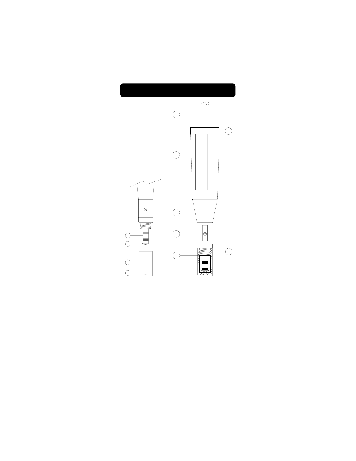
FUNCTIONAL DESCRIPTION PROBE
3
4
4
1
7
8
10
9
5
6
1. D.O. Probe
2. Protective Cap
3. Watertight Shielded Cable
4. Polypropylene Probe Body
5. Temperature Sensor
6. O-Ring Seal
7. Silver Chloride Anode
8. Platinum Cathode (sensor)
9. Oxygen Permeable PTFE Membrane
10. Membrane Cap
3
2
Page 6
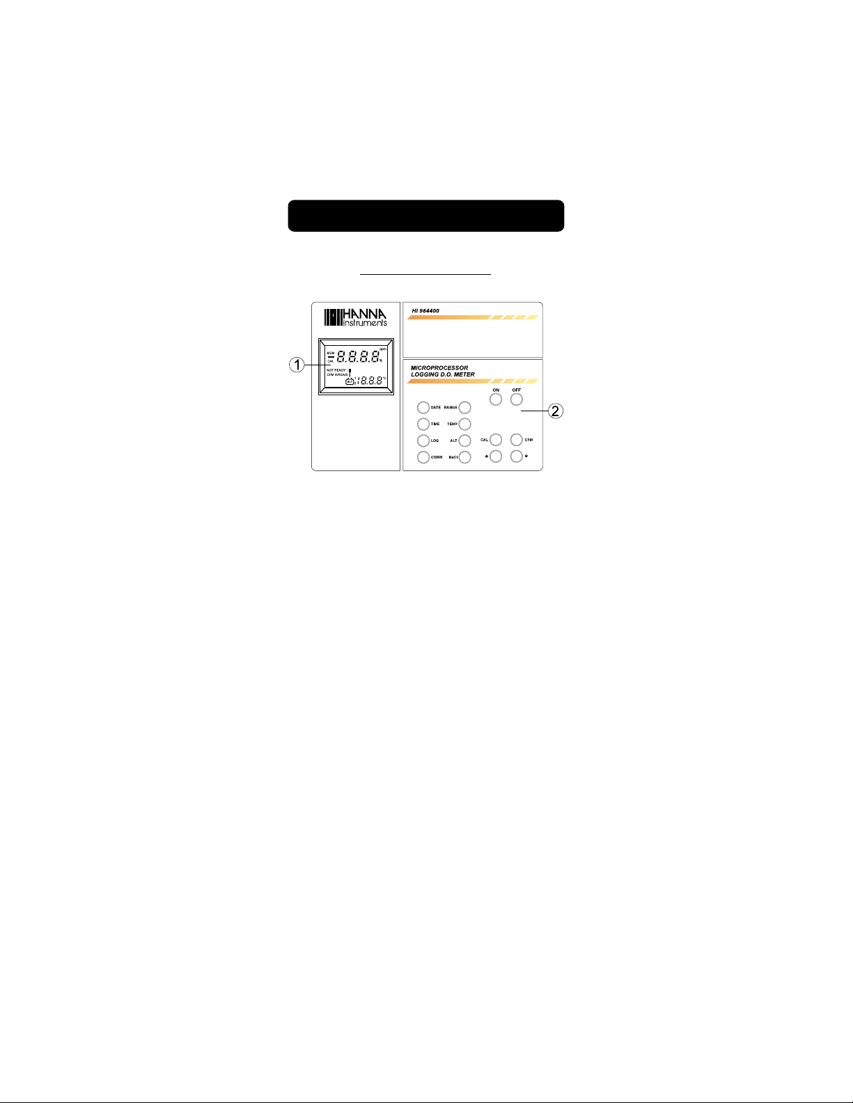
FUNCTIONAL DESCRIPTION OF HI964400
THE FRONT PANEL
1. Liquid Crystal Display
2. Keyboard:
ALT key to display altitude settings
CAL key to enter or exit the calibra-
tion mode; to enable or disable the date or time settings; to start or exit the D.O.
logging mode
CFM key to confirm the calibration val-
ues
COMM key to display the RS232C baud
rate and command prefix
DATE key to display the date
LOG key to display the lot number on
the primary LCD and the page
number on the secondary
one. Press again to display
the sample number of the lot
!!
! key to select the calibration value;
!!
to set date, time, logging interval; to set the altitude and
the salinity factors; to set
the baud rate and command
4
Page 7
prefix for communication to
PC
NaCl key to display salinity settings
OFF key to turn the meter on off
ON key to turn the meter on
RANGE key to select dissolved oxygen
measurement mode in ppm
or in %
TEMP key to select temperature mea-
surement mode
TIME key to display the time
""
" key to select the calibration value;
""
to set date, time, logging interval; to set the altitude and
the salinity factors; to set
the baud rate and command
prefix for communication to
PC.
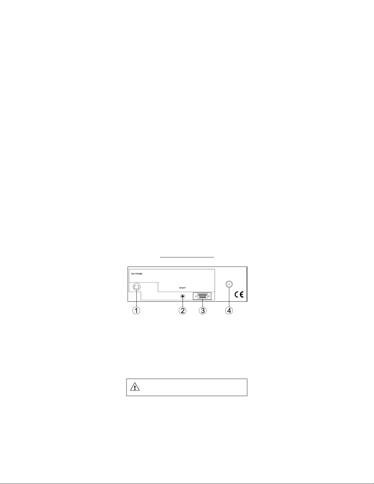
THE REAR PANEL
1. Socket for D.O. Probe
2. Reset Button
3. RS 232C Connector
4. DC Power Socket (for HI710005 or
HI710006)
Unplug the meter from the power supply
before replacing the fuse.
5
Page 8
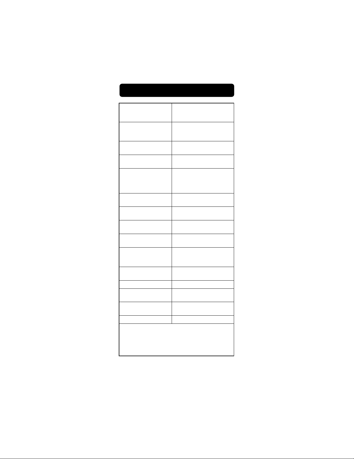
SPECIFICATIONS OF HI964400
Range D.O. ppm 0.00 to 45.00
Resolution D.O. ppm 0.01
Accuracy D.O. ±1.5% of full scale
Typical EMC D.O. ±1.5% of full scale
Deviation Temp. °C ±0.5
Calibration D.O. single or double point at 0%
Altitude Compensation 0 to 1,900 m (6,230')
Salinity Compensation 0 to 40 g/l
Temperature
Compensation 0.0 to 50.0°C (32 to 122°F)
Probe HI76407/2 with
Logging Interval 1, 15, 30 seconds
Computer RS 232C (optoisolated)
Interface
Power Power socket for 12 VCD
Environment 0 to 50°C (32 to 122°F);
Dimensions 230x170x70 mm
Weight 1 kg (2.2 lb.)
Response Time The response time is approximately
20 seconds for a 95% reading at a constant temperature
of 25°C. The response time for low oxygen readings or
at low temperature is approximately 40 seconds. Allow
more time to obtain more accurate readings.
D.O. % 0.0 to 300.0
Temp. °C 0.0 to 50.0
D.O. % 0.1
Temp. °C 0.1
Temp. °C ±0.5
(HI 7040) and 100% (in air)
Temp. °C single point or double point
at 0.0°C and/or 50.0°C
Resolution 100 m (328')
Resolution 1 g/l
2 meters (6.7') cable
or 1, 2, 5, 15, 30, 60, 120,
180 minutes
95% RH
(9.1x6.7x2.7")
6
Page 9
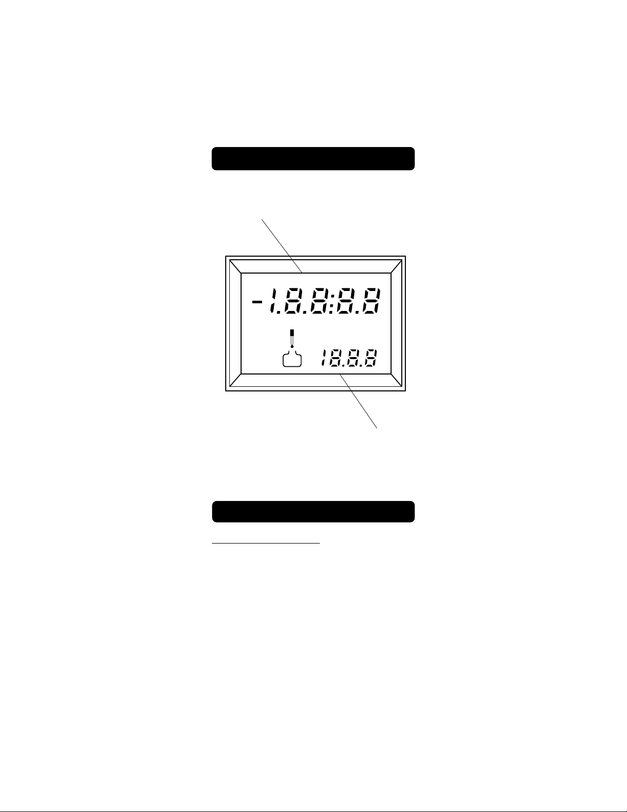
LCD FUNCTIONAL DESCRIPTION
Pri
mary Display
DATEppm TIME
CFM MEM
WRONG
CAL
LOG
BUF
°C
1
2
INTV
m
S
Secondary Display
OPERATIONAL GUIDE
POWER CONNECTION
Plug the 12VDC adapter to the meter and to
the mains.
HI964400 uses an EEPROM to retain the
D.O. calibration and temperature calibration
as well as the serial communication setting.
The instrument will store the respective data
after a calibration or serial communication
setting, even when it is not plugged-in.
7
Page 10

PROBE CONNECTION & PREPARATION
S
To prepare the instrument for use, connect
the D.O. probe to the meter securely by
aligning the pins with the socket located on
the back of the meter, pushing the plug in
and tightening the threaded ring.
All probes shipped from Hanna Instruments
are dry. To hydrate the probe and prepare it
for use, connect it to the meter and proceed
as follows.
1. Remove the red and black plas-
hipping
cap
tic cap. This cap is for shipping
purposes and can be thrown
away.
2. Wet the sensor by soaking the
bottom 2½ cm (1") of the probe
black
red
in electrolyte (HI 7041S) for 5 minutes.
3. Rinse the membrane cap (HI 76407A supplied in the kit with the meter) with electrolyte solution while shaking it gently.
Refill with clean electrolyte solution.
4. Gently tap the sides of the membrane cap
with your finger tip to
ensure that no air
bubbles remain trapped.
To avoid damaging the
membrane, do not tap
the membrane directly
on the bottom.
FILL FIRST
THEN TAP
5. Make sure that the rubber O-ring sits properly
inside the membrane
cap.
THEN SCREW
BACK ON
6. With the sensor facing down,
slowly screw the cap clockwise.
Some electrolyte will overflow.
When not in use and during polarization (see below), place the protective transparent cap supplied in
the kit with the meter.
8
Page 11

TURNING THE METER ON
To switch the meter on, press
ON
the ON key and let the probe
in the auto-conditioning (polarization) mode before proceeding. After approximately
5 minutes, the instrument can
be calibrated (see page 17).
If the probe is disconnected,
the meter will display "----".
ppm
°C
This also indicates the possibility of a broken
probe cable.
PROBE POLARIZATION
The probe is under polarization with a fixed
voltage of approximately 800 mV.
Probe polarization is essential for stable measurements with the same recurring degree of
accuracy.
With the probe properly polarized, oxygen is
continually "consumed" when it passes
through the sensitive diaphragm and dissolves
in the electrolyte solution contained in the
probe.
If polarization is interrupted, the electrolyte
solution continues to be enriched with oxygen until it reaches an equilibrium with the
surrounding solution.
Whenever measurements are taken with a
non-polarized probe, the oxygen level revealed
is both that of the tested solution as well as
that present in the electrolyte solution. This
reading is incorrect.
The calibration of this instrument is very
simple.
Before proceeding with the calibration make
sure the probe is ready for measurements
(see page 8), i.e. the membrane cap is filled
with electrolyte and the probe is connected
9
Page 12

to the meter and properly polarized.
For an accurate calibration, it is recommended
to wait for 5 or 10 minutes to ensure precise
conditioning of the probe.
Keep the protective cap on during the polarization time and remove it for the calibration
and the measurements.
Follow the calibration procedure on page 17.
D.O. MEASUREMENTS (in ppm or in %)
Make sure the meter has been calibrated
(see page 17) and the protective cap has
been removed.
Salinity and Altitude compensation
If the sample contains significant concentration of salinity or if you are performing
measurements at an altitude different from
sea level, the readout values must be corrected, taking into account the lower degree of oxygen solubility in such occasions
as explained on pages 23-25.
Remember to set the altitude and/or the
salinity before taking any D.O. measurements. The meter will automatically compensate for these factors.
Taking measurements
Immerse the tip of the probe in the sample to
be tested. Make sure the temperature sensor
is also immersed.
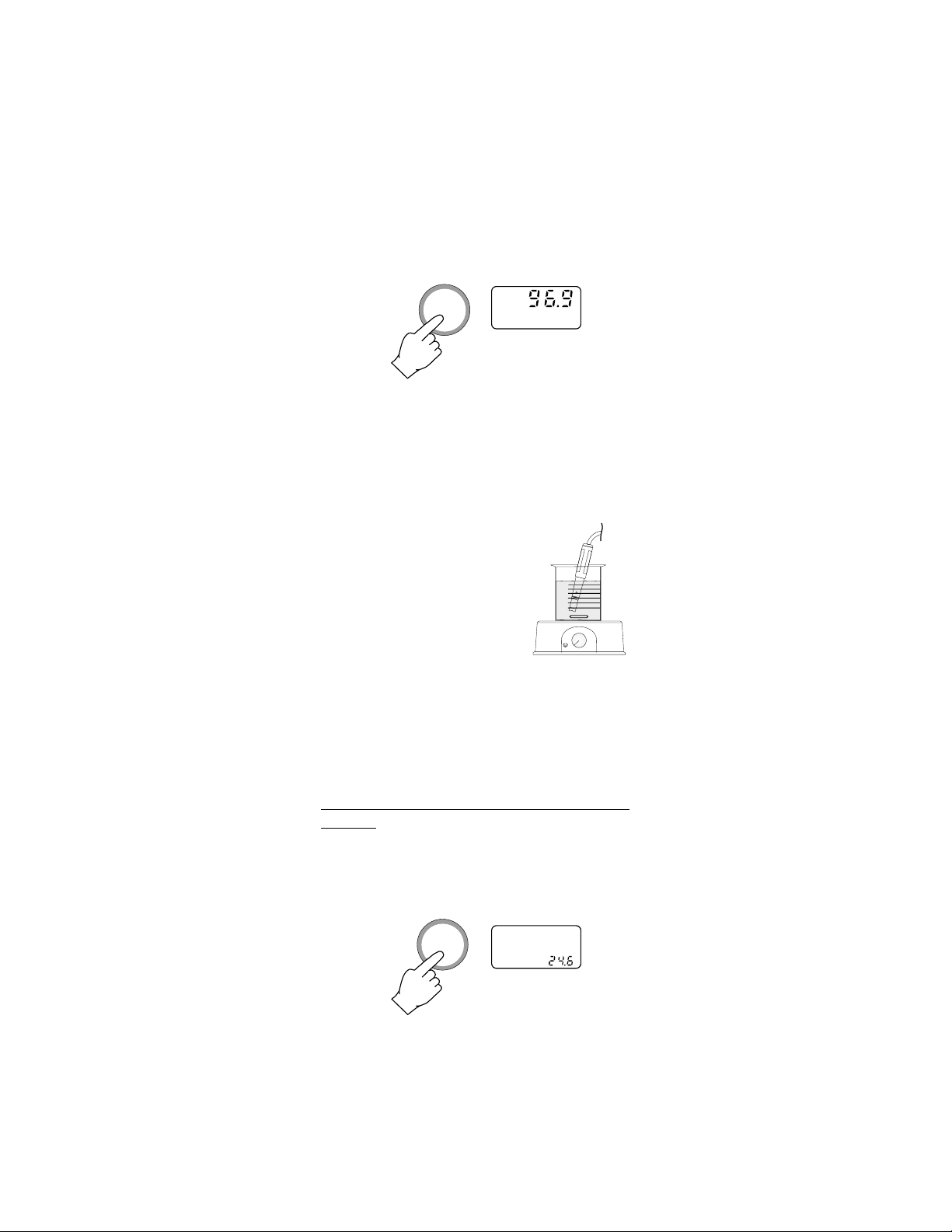
Press the RANGE key to display D.O. measurements. Allow approximately one minute
for the meter to stabilize and
read the
ppm
value of dissolved oxygen on
the display.
RANGE
10
Page 13
Press the RANGE key to change the reading
from ppm to % and vice-versa.
RANGE
For accurate dissolved oxygen measurements
a water movement of 0.3 m/sec is required
at a minimum. This is to ensure that the
oxygen-depleted membrane surface is constantly replenished. A moving stream will
provide adequate circulation.
The use of a magnetic stirrer to ensure a certain velocity in the fluid is recommended. In this way, errors
due to the diffusion of the
oxygen present in the air in
the solution are reduced to
a minimum.
At all times, the time necessary for thermal
equilibrium to occur between the probe and
the measurement sample must be allowed (a
few minutes if the temperature difference is
only several degrees).
TAKING TEMPERATURE MEASUREMENTS
The probe has a built-in temperature sensor.
Press the TEMP key to display the measured
temperature on the secondary display.
TEMP
11
°C
Page 14

Allow the probe to reach the thermal equilibrium before taking any measurement. Reaching thermal equilibrium can take several minutes. The greater the difference between the
temperature at which the probe was stored
and the temperature of the sample, the longer
the time will be.
If "----" is displayed, it indicates that the D.O. probe is
not properly connected or the
°C
temperature is out of range.
This also indicates the possibility of a broken
probe cable.
SETTING THE DATE AND THE TIME AND
THE LOGGING INTERVAL
Press the DATE key to display the date. The
month and the day will be displayed on the
primary LCD, the year on the secondary one.
DATE
DATE
Press the CAL key to enter the setting mode,
the month starts blinking.
CAL
DATE
Use the UP or DOWN arrow keys to select
the month.
12
Page 15
Press the RANGE key, the day starts blinking.
DATE
RANGE
Use the UP or DOWN arrow keys to select
the day.
Press the RANGE key and the year on the
secondary LCD will blink.
RANGE
DATE
Use the UP or DOWN arrow keys to select
the year.
Press the CAL key to
CAL
exit the date setting
mode.
13
Page 16

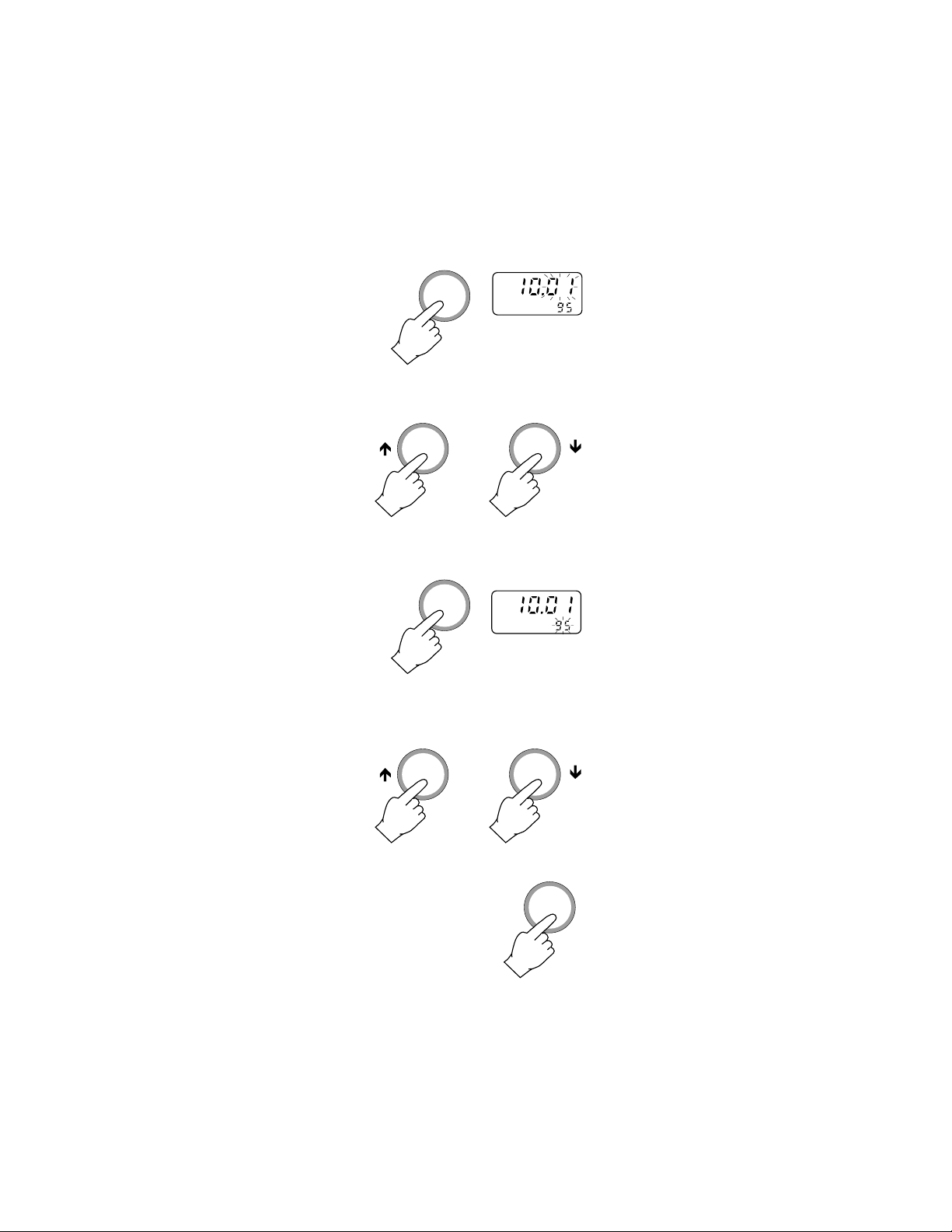
Press the TIME key to display the time. The
hour and the minutes will be displayed on the
primary LCD, the logging interval on the secondary one.
TIME
TIME
INTV
S
Press the CAL key to enter the setting mode,
the hour will start blinking.
TIME
CAL
INTV
S
Use the UP or DOWN arrow keys to select
the hour.
Press the RANGE key and the minutes will
start blinking.
TIME
RANGE
INTV
S
Use the UP or DOWN arrow keys to select
the minutes.
14
Page 17

Press the RANGE key and the logging interval on the secondary LCD will start blinking
(m = minutes, s = seconds).
TIME
RANGE
INTV
S
Use the UP or DOWN arrow keys to select
the logging interval.
Press the CAL key to
exit the time setting
CAL
mode.
VIEWING THE DATE AND THE TIME
Press the DATE key to display the date. The
month and the day will be displayed on the
primary LCD, the year on the secondary one.
DATE
DATE
15
Page 18

Press the TIME key to display the time. The
hour and the minutes will be displayed on the
primary LCD, the logging interval on the secondary one.
TIME
TIME
INTV
m
RESET BUTTON
The RESET button is used when the instrument displays erroneous messages due to
strong electrical interference or when the
instrument's power supply was disconnected
before the meter was switched off.
It is necessary to press the RESET button
and restart the entire operation.
Calibration points should remain memorized.
It is recommended to verify calibration before
proceeding.
16
Page 19

D.O. CALIBRATION
For greatest accuracy, it is recommended
that the instrument is calibrated frequently.
The standard calibration program of the meter
is prepared for 2 (maximum) values: 0.0%
(zero calibration) and 100.0% (slope cali-
bration).
The meter is equipped with a stability indicator and the user will be guided step by step
with easy indications on the display during
the D.O. calibration. This will make the calibration a simple and error-free procedure.
The zero calibration of the HI964400 is very
stable, therefore this procedure needs only to
be performed whenever the probe or the
membrane is replaced.
However, because the slope calibration is
more critical, it is recommended to per-
form this procedure every week.
INITIAL PREPARATION
• Pour small quantities of
HI7040 Zero Oxygen solu-
0
4
0
I 7
H
tion into a beaker. If possible, use a plastic beaker to minimize any EMC
HI 7040
interferences.
• Make sure the probe is ready for measurements (see initial preparation at
page 8), i.e. the membrane is filled with
electrolyte and the probe is connected to
the meter.
• Switch the meter on by
ON
pressing the ON key.
• For an accurate calibration, it is recommended
to wait for at least 15
17
Page 20

minutes to ensure precise
conditioning of the probe.
• Remove the protective cap
from the D.O. probe.
• Set the appropriate altitude
factor (see page 23). Make
sure the salinity factor is set
to zero (see page 25).
ZERO CALIBRATION
• Dip the probe into HI 7040
zero oxygen solution and
stir gently for 2-3 minutes.
• Press the CAL key and the "BUF" indicator will blink until the reading is stable.
CAL
BUF
%
• As soon as the reading is stable, the
"CFM" indicator will start blinking. Press
the CFM key to confirm the "0.0%" D.O.
reading.
CFM
• If the reading is not close to the selected
value, "WRONG
%
1
BUF
" and "WRONG " will
CFM
blink alternatively.
WRONG
%
BUF
WRONG
%
18
Page 21

If the reading is within the margins (±15%),
the meter stores the value (and adjusts
the offset point). The meter will then proceed with the next calibration point.
• Press the CAL key
and the calibration
process is ended
with only the zero
CAL
of the meter calibrated. For a twopoint calibration do
not press the CAL
key and follow the
procedure below.
SLOPE CALIBRATION
It is suggested to perform the slope calibration in saturated air.
• Rinse the probe in a large amount of clean
water to remove any residual zero oxygen
solution.
Note: If you did not perform the zero calibra-
tion procedure, press the CAL key and
then the DOWN key to select the 100%
calibration value.
CAL
• Dry the probe tip and allow a few minutes
for the LCD readout to stabilize. The "BUF"
indicator will blink until the reading is
stable.
%
BUF
19
Page 22

• As soon as the reading is stable, the
"CFM" indicator will start blinking. Press
the CFM key to confirm the "100.0%"
D.O. reading.
CFM
• If the reading is not close to the selected
value, "WRONG
%
1
BUF
" and "WRONG " will
CFM
blink alternatively.
WRONG
%
BUF
WRONG
%
• If the reading is within the margins (±15%),
the meter stores the value (and adjusts
the slope point). The calibration is ended
and the meter will then revert to the normal measurement mode.
Note:
• HI 964400 has automatic buffer recog-
nition function. Press the UP or DOWN
arrow keys to select the desired calibration value, but if these keys are
pressed, the automatic buffer recognition function is disabled.
• Press the CAL
key at any time
to exit the calibration mode.
CAL
20
Page 23
TEMPERATURE CALIBRATION
Each meter has been factory calibrated for
the temperature with the D.O. probe supplied
and is ready for measurements.
The D.O. probes are interchangeable and no
temperature calibration is needed should the
probe be replaced.
If, for any reason, the temperature measurements are out of accuracy, the temperature
re-calibration should be carried out.
For an accurate re-calibration, contact your
nearest Hanna Service Center or follow the
procedure below (for technical personnel only).
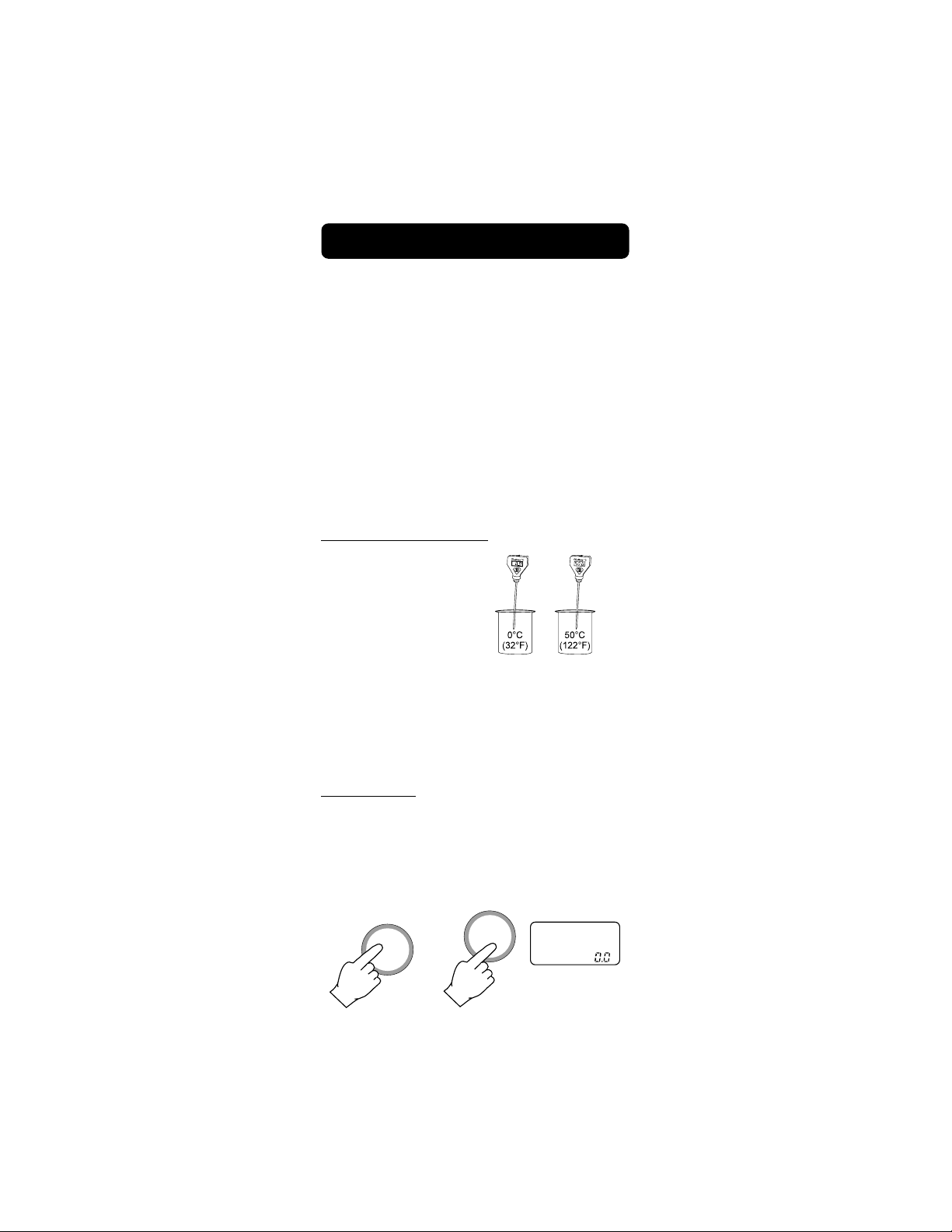
INITIAL PREPARATION
• Prepare a beaker
containing ice (at
0.0°C/32°F) and
water and another
one containing
hot water (at a
temperature of 50.0°C/122°F). Place insulation material around the container to minimize temperature changes.
• Use a ChecktempC or a calibrated ther-
mometer with a resolution of 0.1°C as a
reference thermometer.
PROCEDURE
• Switch the meter on while pressing the
CAL key. The "CAL" indicator will be lit.
The secondary LCD section will show
"0.0°C".
ON
CAL
CAL
°C
21
Page 24

• Immerse the D.O.
probe in the vessel with the ice
and water.
• Wait for about 30 seconds. Press the
CFM key. The secondary LCD section will
show "50.0°C".
CFM
CAL
°C
• Immerse the D.O.
probe in the vessel with hot water.
• Wait for about 30
CFM
seconds. Press
the CFM key.
• The temperature calibration procedure is
now completed.
22
Page 25

ALTITUDE COMPENSATION
Press the ALT key and the altitude factor
will be displayed.
ALT
Use the UP and the DOWN keys to set the
altitude between 0 and 1900 m, in steps of
100 m (1 meter = 3.28 feet).
Altitude affects D.O. concentration decreasing its value. The table on the following page
reports the maximum oxygen solubility at
various temperatures and altitudes.
23
Page 26

°C
10
12
14
16
18
20
22
24
26
28
30
32
34
36
38
40
Altitude, Meters above Sea Level
1500 m
0 m
13.6
14.1
14.6
0
13.8
2
13.1
4
12.4
6
11.8
8
11.3
10.8
10.3
9.9
9.5
9.1
8.7
8.4
8.1
7.8
7.5
7.3
7.1
6.8
6.6
6.4
13.3
12.7
12.0
11.4
10.9
10.4
9.9
9.7
9.2
8.8
8.4
8.1
7.8
7.5
7.2
7.1
6.9
6.6
6.4
6.2
12.9
12.2
11.6
11.0
10.5
10.1
9.6
9.2
8.7
8.5
8.1
7.8
7.5
7.3
7.0
6.8
6.6
6.3
6.2
6.0
13.2
12.4
11.9
11.2
10.6
10.2
9.7
9.3
8.9
8.6
8.2
7.8
7.5
7.3
7.0
6.8
6.6
6.4
6.1
5.9
5.8
1200 m
12.7
12.0
11.4
10.8
10.3
9.8
9.4
9.0
8.6
8.3
7.9
7.7
7.3
7.0
6.8
6.5
6.4
6.2
5.9
5.7
5.6
900 m
600 m
300 m
1800 m
12.3
11.6
11.0
10.4
9.9
9.5
9.1
8.7
8.3
8.0
7.7
7.3
7.1
6.8
6.6
6.3
6.1
6.0
5.7
5.6
5.4
11.8
11.2
10.6
10.1
9.6
9.2
8.8
8.3
8.0
7.7
7.4
7.1
6.8
6.6
6.3
6.1
5.9
5.8
5.5
5.4
5.2
°F
32.0
35.6
39.2
42.8
46.4
50.0
53.6
57.2
60.8
64.4
68.0
71.6
75.2
78.8
82.4
86.0
89.6
93.2
96.8
100.4
104.4
24
Page 27

SALINITY COMPENSATION
Press the NaCl key and the salinity factor
will be displayed.
NaCl
Use the UP and DOWN keys to set the
salinity between 0 and 40 g/l.
Salinity affects D.O. concentration decreasing its value. Below is a table showing the
maximum solubility of oxygen at various temperature and salinity.
Salinity (g/l) at Sea Level
°C
0 g/l
10 g/l
20 g/l
30 g/l
35 g/l
°F
12
14
16
18
20
22
24
26
28
10
11.3
10.8
10.3
9.9
9.5
9.1
8.7
8.4
8.1
7.8
10.6
10.1
9.7
9.3
8.9
8.5
8.2
7.9
7.6
7.4
9.9
9.5
9.1
8.7
8.4
8.0
7.8
7.5
7.2
7.0
9.3
8.9
8.6
8.2
7.9
7.6
7.3
7.1
6.8
6.6
9.0
8.6
8.3
8.0
7.6
7.4
7.1
6.9
6.6
6.4
50.0
53.6
57.2
60.8
64.4
68.0
71.6
75.2
78.8
82.4
TEMPERATURE COMPENSATION
The D.O. probe has a built-in sensor for
temperature so that the D.O. readings are
automatically compensated for temperature
effects.
25
Page 28

LOGGING FUNCTION
This function allows to log D.O. (in ppm or %)
together with the temperature automatically
without the necessity of an operator and for a
long period of time. All logged data can be
stored into a PC through the RS232C port.
The lot number goes from 1 to 99 and then
back to #1. The maximum capacity per lot is
8000 samples.
Set the appropriate logging interval (see
page12). Select between 1, 15, 30 seconds
or 1, 5, 30, 60, 120, 180 minutes.
Press the RANGE key
first (to select D.O. read-
RANGE
ings in ppm or in %),
then press the LOG and
then CAL key to enter
the logging mode.
LOGLOG
CAL
Press the RANGE key to display the measurement reading during the logging mode.
RANGE
26
Page 29
Once in the logging mode, the interval cannot
be changed.
Exit the logging mode first (by pressing the
LOG and then CAL key) before setting a new
interval.
LOGLOG
CAL
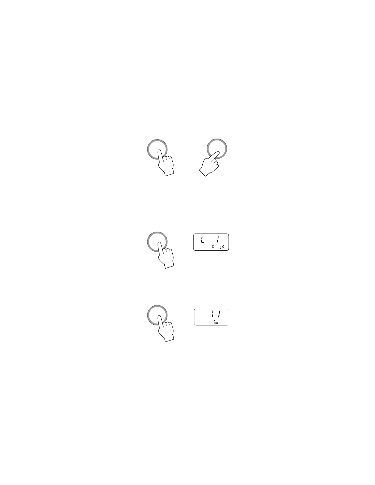
During logging, you can check some information about the logged data.
Press the LOG key and the primary LCD will
show the current lot number and the secondary LCD will display the current page number.
LOGLOG
Press the LOG key again to display the
current sample number (the number of readings that have been stored in the current lot).
LOGLOG
27
Page 30

TO STOP LOGGING
To stop logging press the LOG and then CAL
key.
LOGLOG
The display will show the next lot number.
LOGLOG
CAL
L 2
OFF
Note: if the OFF key is
pressed while logging,
the meter will stop the
logging first and then
will turn off.
MEMORY ORGANIZATION
The memory used for storing the logged data
is divided into 16 pages. The capacity of
each page is 500 samples. It starts to log
from page 16 downwards until 1 and then 16
again, overwriting the previous data. However,
when this happens the LCD will show page
"0", indicating the overwriting has occurred.
Each time a new logging period starts, it
automatically starts from a new page.
28
Page 31

When the samples collected for a single lot
are more than the limit (8000 samples) the
meter will stop logging automatically.
TO CLEAR LOGGED DATA
The entire logged data can be cleared by
pressing the ON and the LOG keys simultaneously.
ON
+
LOGLOG
The choice has to be confirmed by pressing
the CFM key.
CFM
The next logging will
start from page 16.
29
Page 32

INTERFACE WITH PC
Data transmission from the instrument to the
PC is now much easier with the new HI 92000
Windows® compatible application software offered by Hanna Instruments.
User friendly, HI 92000 offers a variety of
features and has an on line help feature to
support you throughout all situations.
HI92000 allows you to use the powerful
means of the most diffused spread sheet
programs (e.g. Excel©, Lotus 1-2-3©). Simply
run your favorite spread sheet and open the
file downloaded by HI92000. It is then possible to make any elaboration available with
your software (e.g. graphics, statistical analysis).
To install HI 92000 you need a 3.5" drive and
few minutes to follow the instructions conveniently printed on the disk's label.
Contact your Hanna Dealer to request a copy.
To connect your HI964400 to the PC use
HI 920010, available through your Hanna
Dealer. Make sure that your meter is switched
off and plug the connectors, one into the
meter RS232C connector, the other into the
serial port of your PC.
Note: Cables different from the HI920010
may use a different configuration. In
such case any communication between
the meter and the PC is not possible.
Excel© Copyright of "Microsoft Co."
Lotus 1-2-3© Copyright of "Lotus Co."
Windows® and Windows Terminal® are registered Trademark of "Microsoft Co."
30
Page 33

PROBE & MEMBRANE MAINTENANCE
The oxygen probe body is made of reinforced
plastic for maximum durability.
A thermistor temperature sensor provides temperature measurements of the sample tested.
It is always recommended that the protective
cap be kept on the probe when the probe is
not in use to provide protection against damage and dirt.
To replace the membrane or refill with
electrolyte, proceed as follows:
• Remove the protective
cap by gently twisting
and pulling it off the
body of the probe (see
fig. 1).
TWIST
AND
PULL
• Unscrew the membrane
cap by turning it counterclockwise (see fig.2).
• Wet the sensor by soaking the bottom 2½ cm
(1") of the probe in electrolyte (HI 7041S) for 5
minutes.
• Rinse the new membrane cap (HI 76407A)
supplied with the meter
with electrolyte solution
while shaking it gently.
Refill with clean electrolyte solution.
• Gently tap the sides of
the membrane cap with
your finger tip to ensure
that no air bubbles remain trapped. Do no directly tap the bottom
31
fig. 1
UNSCREW
fig. 2
Page 34

with your finger as this will damage the
membrane.
• Make sure that the rubber O-ring sits
properly inside the membrane cap.
• With the sensor facing down, slowly
screw the membrane cap clockwise.
Some electrolyte will overflow.
The Platinum cathode (#8 in the Functional
Description at page 3) should always be
bright and untarnished. If it is tarnished or
stained, which could be due to contact with
certain gases or extended use with a loose
or damaged membrane, the cathode should
be cleaned. You can use a clean lint-free
cardboard or cloth. Rub the cathode very
gently side to side 4-5 times. This will be
enough to polish and remove any stains
without damaging the platinum tip. Afterwards, rinse the probe with deionized or
distilled water and install a new membrane
cap using fresh electrolyte and follow the
steps above. Re-calibrate the instrument.
Important: in order to have accurate and
stable measurements, it is important that
the surface of the membrane is in perfect
condition. This semipermeable membrane
isolates the sensor elements from the environment but allows oxygen to enter. If any
dirt is observed on the membrane, rinse
carefully with distilled or deionized water. If
any imperfections still exist, or any damage is evident (such as wrinkles or tearsholes), the membrane should be replaced.
Make sure that the O-Ring sits properly in
the membrane cap.
32
Page 35

ADDITIONAL INFORMATION
(for Technical Personnel only)
If you are not using Hanna Instruments
HI92000 application software, please find here
below some additional information to help
your connection to the PC.
SETTING THE BAUD RATE AND THE COMMAND PREFIX
The transmission speed (baud rate) of your
HI964400 and of the external device must be
the same.
To set the baud rate of the meter press the
COMM key, the primary LCD shows the current baud rate.
COMMCOMM
The following baud rate can be selected
through the UP or DOWN arrow keys: 150,
300, 600, 1200 (factory setting), 2400, 4800
and 9600.
33
Page 36

Press the COMM key to confirm the setting
and the primary LCD shows the current com-
mand prefix; 16 is the factory setting.
COMMCOMM
Note: the Command Prefix does not have to
be changed using HI92000 Hanna Soft-
ware.
Select a different command prefix (between 0
to 47 decimal) by pressing the UP or DOWN
arrow keys.
Press the COMM key to confirm the setting.
34
COMMCOMM
Page 37

SENDING COMMANDS FROM PC
With terminal programs such as Telix® and
Windows Terminal®, it is possible to remotely
control your HI 964400. Use HI 920010 cable
to connect the meter to the PC, start the
terminal program and set the communication
options as follows: 8, N, 1, no flow control.
Command Types
To send a command to the D.O. meter the
scheme is:
<DLE> <
command>
<CR>
This line makes the computer send a Data
Link Escape character, the command expressed as a number or a 3-character sequence) and a CR character.
Note: Windows Terminal® and all the other
terminal programs that support the
ANSI escape sequence, represent the
DLE character by the string '^P' and
the CR character by the string '^M'.
E.g. the line '^PPPM^M' sets the range
to ppm.
Commands not requiring an answer from
the meter:
PPM sets the range to ppm D.O.
PER sets the range to % D.O.
OFF is equivalent to pressing the OFF key
Commands requiring an answer:
DO? Causes the meter to send the D.O.
(% or ppm will depend on the meter
setting). If the reading is out of range
"Err 1" is sent.
Windows Terminal® are registered Trademark of "Microsoft Co."
TELIX® is registered Trademark of "Deltacomm"
35
Page 38

TM? Causes the meter to send the tem-
perature value. If the reading is out of
range "Err 3" is sent.
DA? Requests the meter to send the date
E.g. "022896" for 28th Feb. 96
TI? Requests the meter to send the time
E.g. "233001"
for 23:30 hr, 1 sec. as interval
"233002"
for 23:30 hr, 15 sec. as interval
"233003"
for 23:30 hr, 30 sec. as interval
"233004"
for 23:30 hr, 1 min. as interval
"233005"
for 23:30 hr, 5 min. as interval
"233006"
for 23:30 hr, 30 min. as interval
"233007"
for 23:30 hr, 60 min. as interval
"233008"
for 23:30 hr, 120 min. as interval
"233009"
for 23:30 hr, 180 min. as interval
?ML Requests the meter to send the avail-
able lot number collected in memory.
The transmission begins with <STX>
and terminates with <ETX>. The data
are sent in the following order:
1) stx
2) Lot number
E.g. "01" for lot No. 1
3) Total number of samples per lot
E.g. "1234" for total no. of
samples: 1234.
36
Page 39

4) Channel #1 status
E.g. "1" for ppm logging se-
lected in this lot
"0" for ppm logging not
selected in this lot
5) Channel #2 status
E.g. "1" for % logging selected
in this lot
"0" for % logging not se-
lected in this lot
6) Channel #3 status
E.g. "1" for not used
"0" for not used
7) Channel #4 status
E.g. "1" for temperature logging
selected in this lot
"0" for temperature logging
not selected in this lot
8) ...
Repeat from 2 to 7 for the
next available lot No.
9) etx
?VM Requests the meter to send the se-
lected lot status. The data are sent in
the following order:
1) stx
2) Lot number
E.g. "01" for lot No. 1
3) Total number of samples per lot
E.g. "1234" for total no. of
samples: 1234.
4) Channel #1 status
E.g. "1" for ppm logging se-
lected in this lot
"0" for ppm logging not
selected in this lot
37
Page 40

5) Channel #2 status
E.g. "1" for % logging selected
in this lot
"0" for % logging not se-
lected in this lot
6) Channel #3 status
E.g. "1" for not used
"0" for not used
7) Channel #4 status
E.g. "1" for temperature logging
selected in this lot
"0" for temperature logging
not selected in this lot
8) begin sample time, min
E.g. "59" for 59 minute
9) begin sample time, hour
E.g. "12" for 12 hour
10) begin sample time, day
E.g. "09" for 9th day
11) begin sample time, month
E.g. "09" for September
12) begin sample time, year
E.g. "96" for year 1996
13 ) logging interval
E.g. "0" for 1 second
"1" for 15 seconds
"2" for 30 seconds
"3" for 1 minute
"4" for 5 minutes
"5" for 30 minutes
"6" for 60 minutes
"7" for 120 minutes
"8" for 180 minutes
14) last sample time, min
E.g. "59" for 59 minute
38
Page 41

15) last sample time, hour
E.g. "12" for 12 hour
16) last sample time, day
E.g. "09" for 9th day
17) last sample time, month
E.g. "09" for September
18) last sample time, year
E.g. "96" for year 1996
19) etx end
?DM Requests the meter to send the se-
lected lot data memory. The data are
sent in the following order:
1) stx
2) Lot number
E.g. "01" for lot No. 1
3) Channel #1 status
E.g. "1" for ppm logging se-
lected in this lot
"0" for ppm logging not
selected in this lot
4) Channel #2 status
E.g. "1" for % logging selected
in this lot
"0" for % logging not se-
lected in this lot
5) Channel #3 status
E.g. "1" for not used
"0" for not used
6) Channel #4 status
E.g. "1" for temperature logging
selected in this lot
"0" for temperature logging
not selected in this lot
7) begin sample time, min
E.g. "59" for 59 minute
39
Page 42

8) begin sample time, hour
E.g. "12" for 12 hour
9) begin sample time, day
E.g. "09" for 9th day
10) begin sample time, month
E.g. "09" for September
11) begin sample time, year
E.g. "96" for year 1996
12 ) logging interval
E.g. "0" for 1 second
"1" for 15 seconds
"2" for 30 seconds
"3" for 1 minute
"4" for 5 minutes
"5" for 30 minutes
"6" for 60 minutes
"7" for 120 minutes
"8" for 180 minutes
13) Total number of samples per lot
E.g. "1234" for total no. of
samples: 1234.
14) Logged data in signed integer,
repeat sending in logged channel sequence
sample no. 1
---- send ppm data if ppm is log
selected
---- send % data if %is log selected
---- send temperature data if temperature is log selected
sample no. 2 ...
until the last sample
sample "XXX" is signed hex format.
40
Page 43

15) last sample time, min
E.g. "59" for 59 minute
16) last sample time, hour
E.g. "12" for 12 hour
17) last sample time, day
E.g. "09" for 9th day
18) last sample time, month
E.g. "09" for September
19) last sample time, year
E.g. "96" for year 1996
20) et x e nd
The meter will send "Err6" if in a different
measurement range.
Commands setting parameters:
/ML To select the data lot for data transfer.
E.g. send "/ML05" to select lot no. 5.
If the lot no. is valid, the meter will
send <ACK>, otherwise it will send
<CAN>.
/BR To set the RS232C baud rate.
E.g. send "/BR0" to set the meter to
baud rate of 150
send "/BR1" to set the meter to baud
rate of 300
send "/BR2" to set the meter to baud
rate of 600
send "/BR3" to set the meter to baud
rate of 1200
send "/BR4" to set the meter to baud
rate of 2400
send "/BR5" to set the meter to baud
rate of 4800
send "/BR6" to set the meter to baud
rate of 9600
41
Page 44

/PF To set the RS232C command prefix.
E.g. send "/PF05" to set the com-
mand prefix to 05.
Note: <ACK> will be sent by the meter if the
command received is accepted, otherwise it will send <CAN>.
<ACK> equals to ASCII code 06 and
<CAN> equals to ASCII code 24.
If sample data is out of range "07FFFH"
is sent.
These commands may be sent with either
capital or small letters. Invalid commands will
be ignored. The characters sent by the pH
meter are always capital letters.
42
Page 45

ACCESSORIES
ChecktempC Electronic termometer
(range: -50.0 to 150.0°C)
ChecktempF Electronic termometer
(range: -58.0 to 302°F)
HI 7040M Zero Oxygen Solution, 230 ml
HI 7040L Zero Oxygen Solution, 460 ml
HI 7041S Refilling Electrolyte Solution,
30 ml
HI 710005 115VAC to 12VDC converter
HI 710006 230VAC to 12VDC converter
HI 76407/2 Spare probe with 2 meters (6.7')
cable
HI 76407/10 Spare probe with 10 meters
(33') cable
HI 76407/20 Spare probe with 20 meters
(67') cable
HI 76407A/P 5 spare membranes
HI 92000/16 Windows® 3.11 compatible ap-
plication software
HI 92000/32 Windows® 95 compatible ap-
plication software
HI 920010 25-pin PC connection cable
HI 920010/9 9-pin PC connection cable
MANDOBNR1
Instruction manual
Windows ® is registered Trademark of "Microsoft Co."
43
Page 46

WARRANTY
All Hanna Instruments are warranted for two
years against defects in workmanship and
materials when used for their intended purpose and maintained according to the instructions.
The probes are warranted for a period of
six months.
Damages due to accident, misuse, tampering
or lack of prescribed maintenance are not covered. This warranty is limited to repair or replacement free of charge of the meter only,
whenever due to defect of manufacturing.
If service is required, contact the dealer from
whom you purchased the instrument. If under
warranty, report the model number, date of
purchase, serial number and the nature of the
failure. If the repair is not covered by the
warranty, you will be notified of the charge for
repair or replacement. If the instrument is to be
returned to Hanna Instruments, obtain a Return Goods Authorization from the Customer
Service Department first and then send it with
shipment cost prepaid. When shipping any
instrument, make sure it is properly packaged
for complete protection.
To validate your warranty, fill out and return the
enclosed warranty card within 14 days from the
date of purchase.
All rights are reserved. Reproduction in whole or
in part is prohibited without the written permission of the copyright owner.
Hanna Instruments reserves the right to modify
the design, construction and appearance of its
products without advance notice.
44
Page 47

CE DECLARATION OF CONFORMITY
DECLARATION OF CONFORMITY
We
Hanna Instruments Srl
V.le delle industrie 12
35010 Ronchi di Villafranca (PD)
ITALY
herewith certify that the bench D.O. meter
has been tested and found to be in compliance with the following regulations:
IEC 801-2 Electrostatic Discharge
IEC 801-3 RF Radiated
IEC 801-4 Fast Transient
EN 55022 Radiated, Class B
HI 964400
Date of Issue: 18-04-1996
D.Volpato - Engineering Manager
On behalf of
Hanna Instruments S.r.l.
Recommendations for Users
Before using this product, make sure that it is entirely suitable for the environment
in which it is used.
Operation of this instrument in residential area could cause unacceptable interferences to radio and TV equipments, requiring the operator to take all necessary steps
to correct interferences.
Any variation introduced by the user to the supplied equipment may degrade the
instrument's EMC performance.
To avoid damages or burns, do not perform any measurement in microwave ovens.
45
Page 48

PRINTED IN
ITALY
MANDOBNR1
02/00
http://www.hannainst.com
 Loading...