

Page 1
Instruction Manual
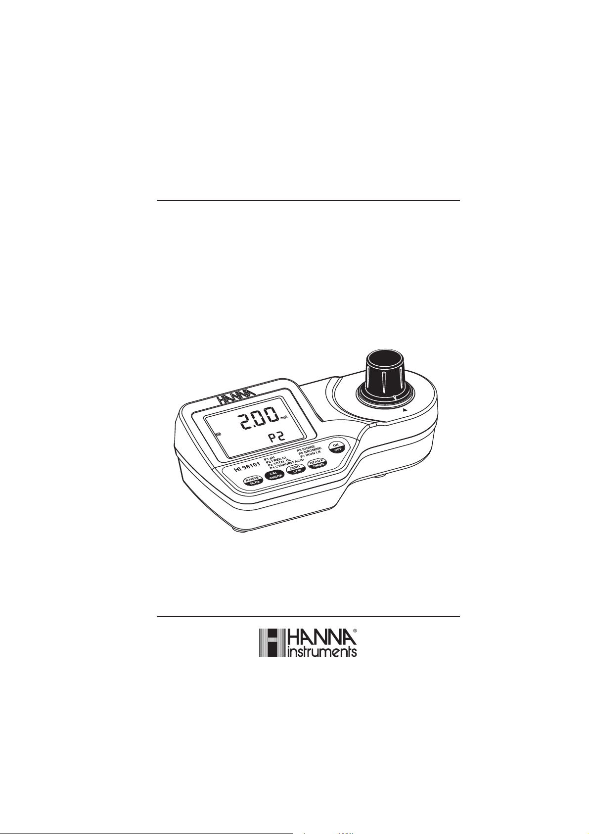
HI 96101C
pH, Chlorine, Cyanuric Acid,
Iodine, Bromine, Iron LR
ISM
www.hannainst.com
1
Page 2

Dear Customer,
Thank you for choosing a Hanna product. This manual will provide you with the necessary
information for the correct use of the instrument. Please read it carefully before using the meter.
If you need additional technical information, do not hesitate to e-mail us at tech@hannainst.com.
TABLE OF CONTENTS
PRELIMINARY EXAMINATION ................................................................................................ 3
GENERAL DESCRIPTION ....................................................................................................... 4
ABBREVIATIONS .................................................................................................................. 5
SPECIFICATIONS ................................................................................................................... 5
PRECISION AND ACCURACY .................................................................................................. 7
PRINCIPLE OF OPERATION ................................................................................................... 8
FUNCTIONAL DESCRIPTION ................................................................................................ 10
ERRORS AND WARNINGS .................................................................................................. 12
GENERAL TIPS FOR AN ACCURATE MEASUREMENT ............................................................. 14
STARTUP ........................................................................................................................... 15
RANGE SELECTION ............................................................................................................. 16
MEASUREMENT PROCEDURE ............................................................................................. 16
VALIDATION PROCEDURE ................................................................................................... 28
CALIBRATION PROCEDURE ................................................................................................. 29
GLP ................................................................................................................................... 32
BATTERY MANAGEMENT .................................................................................................... 33
BATTERY REPLACEMENT .................................................................................................... 33
ACCESSORIES ..................................................................................................................... 34
WARRANTY........................................................................................................................ 35
All rights are reserved. Reproduction in whole or in part is prohibited without the written consent of the copyright owner,
Hanna Instruments Inc., Woonsocket, Rhode Island, 02895 , USA.
2
Page 3
PRELIMINARY EXAMINATION
Please examine this product carefully. Make sure that the instrument is not damaged. If any
damage occurred during shipment, please notify your Dealer.
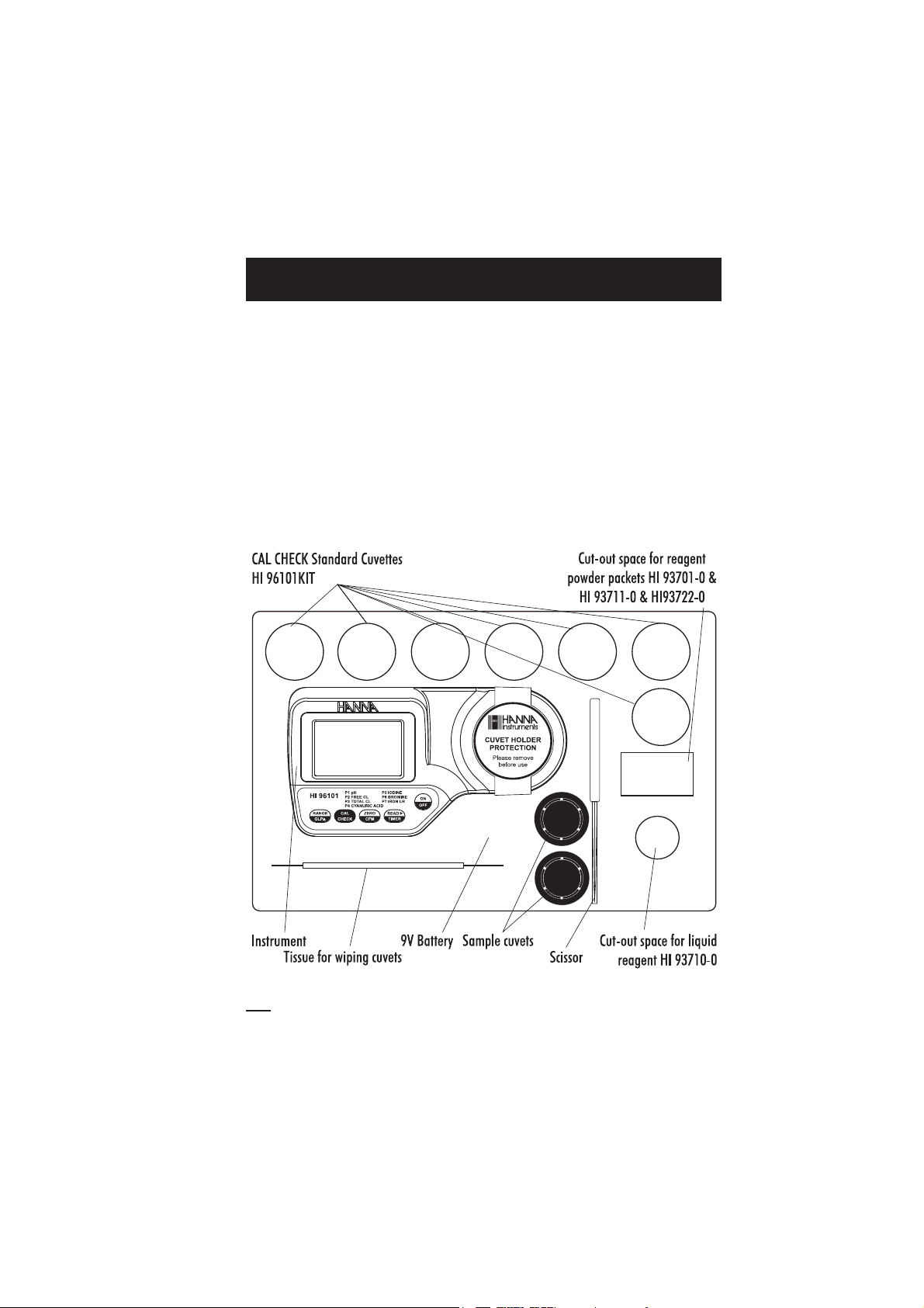
Each HI 96101 Ion Selective Meter is supplied complete with:
• Two Sample Cuvettes and Caps
• Seven CAL CHECK standard cuvettes HI 96101KIT
• 9V Battery
• Tissue for wiping cuvettes
• Instrument quality certificate
• Instruction Manual
• Rigid carrying case
Note:Save all packing material until you are sure that the instrument works correctly. Any
defective item must be returned in its original packing.
3
Page 4

GENERAL DESCRIPTION
The HI 96101 is an auto diagnostic portable microprocessor meter that benefits from Hanna’s
years of experience as a manufacturer of analytical instruments. It has the advanced optical
system based on a special tungsten lamp and a narrow band interference filter that allows most
accurate and repeatable readings. All instruments are factory calibrated and the electronic and
optical design minimizes the need of frequent calibration.
With the powerful CAL CHECKTM validation function, you are able to validate good performance
of your instrument at any time. The validation procedure is extremely user friendly. Just use the
exclusive HANNA ready-made, NIST traceable standards to verify the performance of the
instrument and recalibrate if necessary.
All instruments are splash waterproof and the lamp and filter units are protected from dust or dirt
by a transparent cup. This makes the instruments fulfill field applications. Display messages aid
the user in routine operation. The meter has an auto-shut off feature that will turn off the
instrument after 10 minutes of non use in
calibration mode
The meter uses an exclusive positive-locking system to ensure that the cuvette is in the same
position every time it is placed into the measurement cell. It is designed to fit a cuvette with a
larger neck making it easier to add both sample and reagents. The cuvette is made from special
optical glass to obtain best results.
The HI 96101 meter measures pH, Free and Total Chlorine, Cyanuric Acid, Iodine, Bromine and
Iron Low Range content in water and wastewater samples in the following ranges:
.
measurement mode
or after 1 hour if left in
Parameter Range
pH 6.5 to 8.5 pH
Free Chlorine 0.00 to 5.00 mg/L
Total Chlorine 0.00 to 5.00 mg/L
Cyanuric Acid 0 to 80 mg/L
Iodine 0.0 to 12.5 mg/L
Bromine 0.00 to 10.00 mg/L
Iron LR 0.00 to 1.60 mg/L
The reagents are in liquid and powder form depending on the parameter and they are supplied
in dropper bottles and packets. The amount of reagent is precisely dosed to ensure the maximum
repeatability.
4
Page 5

ABBREVIATIONS
degree Celsius
°C:
degree Fahrenheit
°F:
milligrams per liter. mg/L is equivalent to ppm (parts per million)
mg/L:
milliliter
mL:
millivolts
mV:
US Environmental Protection Agency
USEPA:
SPECIFICATIONS
Range pH 6.5 to 8.5 pH
Free Chlorine 0.00 to 5.00 mg/L
Total Chlorine 0.00 to 5.00 mg/L
Cyanuric Acid 0 to 80 mg/L
Iodine 0.0 to 12.5 mg/L
Bromine 0.00 to 10.00 mg/L
Iron LR 0.00 to 1.60 mg/L
Resolution 0.1 pH
0.01 mg/L under 3.50 mg/L Chlorine
0.10 mg/L above 3.50 mg/L Chlorine
1 mg/L Cyanuric Acid
0.1 mg/L Iodine
0.01 mg/L Bromine
0.01 mg/L Iron LR
Accuracy pH ±0.1 pH @ 25°C
Free Chlorine ±0.03 ±3% of reading @ 25°C
Total Chlorine ±0.03 ±3% of reading @ 25°C
Cyanuric Acid ±1 mg/L ±15% of reading @ 25°C
Iodine ±0.1 mg/L ±5% of reading @ 25°C
Bromine ±0.08 mg/L ±3% of reading @ 25°C
Iron LR ±0.01 mg/L ±8% of reading @ 25°C
Typical EMC Deviation ±0.1 pH
±0.01 mg/L Bromine, Chlorine
±1 mg/L Cyanuric Acid
±0.1 mg/L Iodine
±0.02 mg/L Iron LR
5
Page 6

Light Source Tungsten lamp
Light Detector Silicon Photocell with narrow band interference filter @ 525 nm
Methods For pH: Phenol red method. The reaction with reagents causes a red
tint in the sample.
For Chlorine: Adaptation of the USEPA method and Standard Method
4500-Cl G. The reaction with reagents causes a pink tint in the
sample.
For Cyanuric Acid: Adaptation of the turbidimetric method. The reaction
between cyanuric acid and the reagent causes a white suspension in
the sample.
For Iodine: Adaptation of the EPA, DPD method. The reaction between
iodine and the reagent causes a pink tint in the sample.
For Bromine: Adaptation of the EPA, DPD method. The reaction
between bromine and the reagent causes a pink tint in the sample.
For Iron LR: Adaptation of the TPTZ method. The reaction between
iron and the reagent causes a violet tint in the sample.
Environment 0 to 50°C (32 to 122°F); max 95% RH non-condensing
Battery Type 1 x 9 volt
Auto-Shut off After 10' of non-use in
after 1 hour of non-use in
with last reading reminder.
Dimensions 192 x 104 x 69 mm (7.6 x 4.1 x 2.7")
Weight 360 g (12.7 oz.).
measurement mode
calibration mode
;
;
REQUIRED REAGENTS
Code Parameter Description Quantity/test
HI 93710-0 pH Phenol red 5 drops
HI 93701-0 Free Chlorine DPD Powder Reagent 1 packet
HI 93711-0 Total Chlorine DPD Powder Reagent 1 packet
HI 93722-0 Cyanuric Acid Powder Reagent 1 packet
HI 93718-0 Iodine DPD Powder Reagent 1 packet
HI 93716-0 Bromine DPD Powder Reagent 1 packet
HI 93746-0 Iron LR Powder Reagent 2 packet
6
Page 7
PRECISION AND ACCURACY
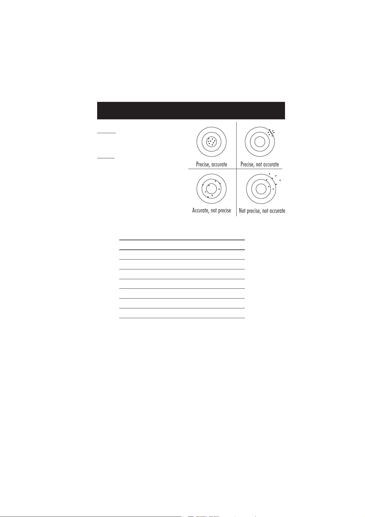
Precision is how closely repeated measurements
agree with each other. Precision is usually
expressed as standard deviation (SD).
Accuracy is defined as the nearness of a test
result to the true value.
Although good precision suggests good accuracy,
precise results can be inaccurate. The figure
explains these definitions.
In a laboratory using a standard solution of the
parameter and a representative lot of reagent
(for each parameter) the following standard
deviations were obtained:
Parameter Standard Solution Standard Deviation
pH 7.0 pH 0.1 pH units
Free Chlorine 1.00 mg/L 0.03 mg/L
Total Chlorine 1.00 mg/L 0.03 mg/L
Cyanuric Acid 20 mg/L 1 mg/L
Iodine 2.5 mg/L 0.1 mg/L
Bromine 2.00 mg/L 0.08 mg/L
Iron LR 0.80 mg/L 0.01 mg/L
7
Page 8

PRINCIPLE OF OPERATION
Absorption of Light is a typical phenomenon of interaction between electromagnetic radiation and
matter. When a light beam crosses a substance, some of the radiation may be absorbed by
atoms, molecules or crystal lattices.
If pure absorption occurs, the fraction of light absorbed depends both on the optical path length
through the matter and on the physical-chemical characteristics of the substance according to the
Lambert-Beer Law:
-log I/Io = ελ c d
or
A = ελ c d
Where:
-log I/I
Therefore, the concentration "c" can be calculated from the absorbance of the substance as the
other factors are known.
Photometric chemical analysis is based on the possibility to develop an absorbing compound
from a specific chemical reaction between sample and reagents. Given that the absorption of a
compound strictly depends on the wavelength of the incident light beam, a narrow spectral
bandwidth should be selected as well as a proper central wavelength to optimize measurements.
The optical system of Hanna's HI 96 series colorimeters is based on special subminiature
tungsten lamps and narrow-band interference filters to guarantee both high performance and
reliable results.
= Absorbance (A)
o
Io= intensity of incident light beam
I = intensity of light beam after absorption
ελ= molar extinction coefficient at wavelength λ
c = molar concentration of the substance
d = optical path through the substance
HI 96 block diagram (optical layout)
A microprocessor controlled special tungsten lamp emits radiation which is first optically
conditioned and beamed to the sample contained in the cuvette. The optical path is fixed by the
diameter of the cuvette. Then the light is spectrally filtered to a narrow spectral bandwidth, to
obtain a light beam of intensity Io or I.
8
Page 9

The photoelectric cell collects the radiation I that is not absorbed by the sample and converts
it into an electric current, producing a potential in the mV range.
The microprocessor uses this potential to convert the incoming value into the desired measuring
unit and to display it on the LCD.
The measurement process is carried out in two phases: first the meter is zeroed and then the
actual measurement is performed.
The cuvette has a very important role because it is an optical element and thus requires
particular attention. It is important that both, the measurement and the calibration (zeroing)
cuvettes, are optically identical to provide the same measurement conditions. Whenever possible
use the same cuvette for both. It is necessary that the surface of the cuvette is clean and not
scratched. This to avoid measurement interference due to unwanted reflection and absorption of
light. It is recommended not to touch the cuvette walls with hands.
Furthermore, in order to maintain the same conditions during the zeroing and the measuring
phases, it is necessary to close the cuvette to prevent any contamination.
9
Page 10
FUNCTIONAL DESCRIPTION
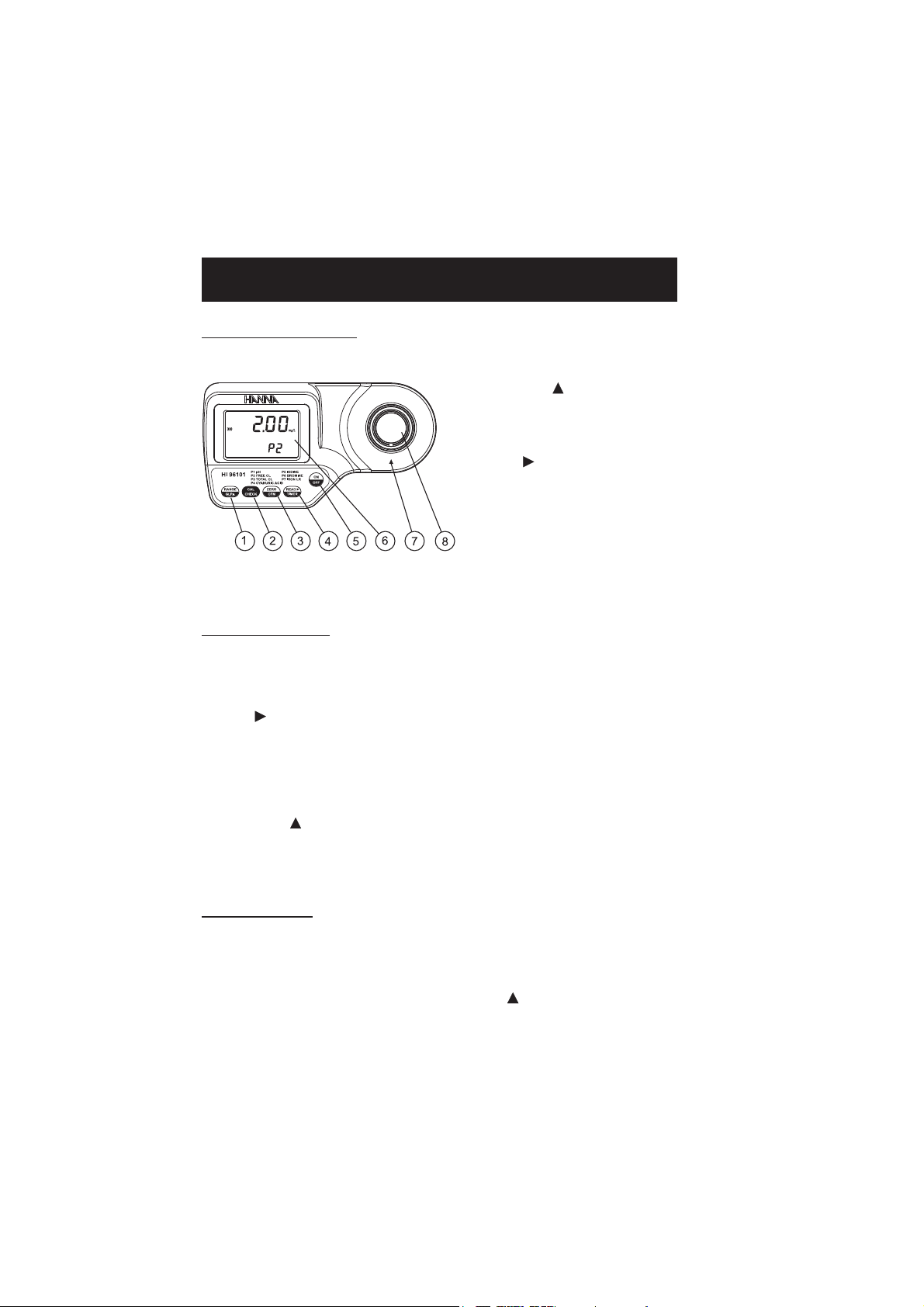
INSTRUMENT DESCRIPTION
1) RANGE/GLP/ key
2) CAL CHECK key
3) ZERO/CFM key
4) READ/ /TIMER key
5) ON/OFF key
6) Liquid Crystal Display (LCD)
7) Cuvette alignment indicator
8) Cuvette holder
KEYPAD DESCRIPTION
• ON/OFF: to turn the meter on and off.
• ZERO/CFM: this is a bi-functional key. Just press to zero the meter prior to measurement,
or confirm edited values. In
• READ/ /TIMER: this is a multi-functional key. In
measurement, or press and hold for three seconds to start a pre-programmed countdown prior
to measurement. In
• CAL CHECK: this is a bi-functional key. Just press to perform the validation of the meter, or
press and hold for three seconds to enter
• RANGE/GLP/ : this is a multi-functional key. In
parameter. Press and hold for three seconds to enter
edit the date and time.
GLP mode
calibration mode
press to confirm factory calibration restore.
measurement mode
press to view the next screen.
calibration mode
measurement mode
GLP mode
.
. In
, press to make a
, press to change the
calibration mode
press to
OPERATING MODES
•
Measurement mode:
•
Calibration mode:
“CAL” tag appears), it enables calibration of the instrument.
•
GLP mode
consulting of user calibration date or restore factory calibration.
default operation mode, enables both validation and measurement.
may be entered by keeping CAL CHECK pressed for three seconds (the
may be entered by pressing RANGE/GLP/ (“GLP” appears), it enables
10
Page 11
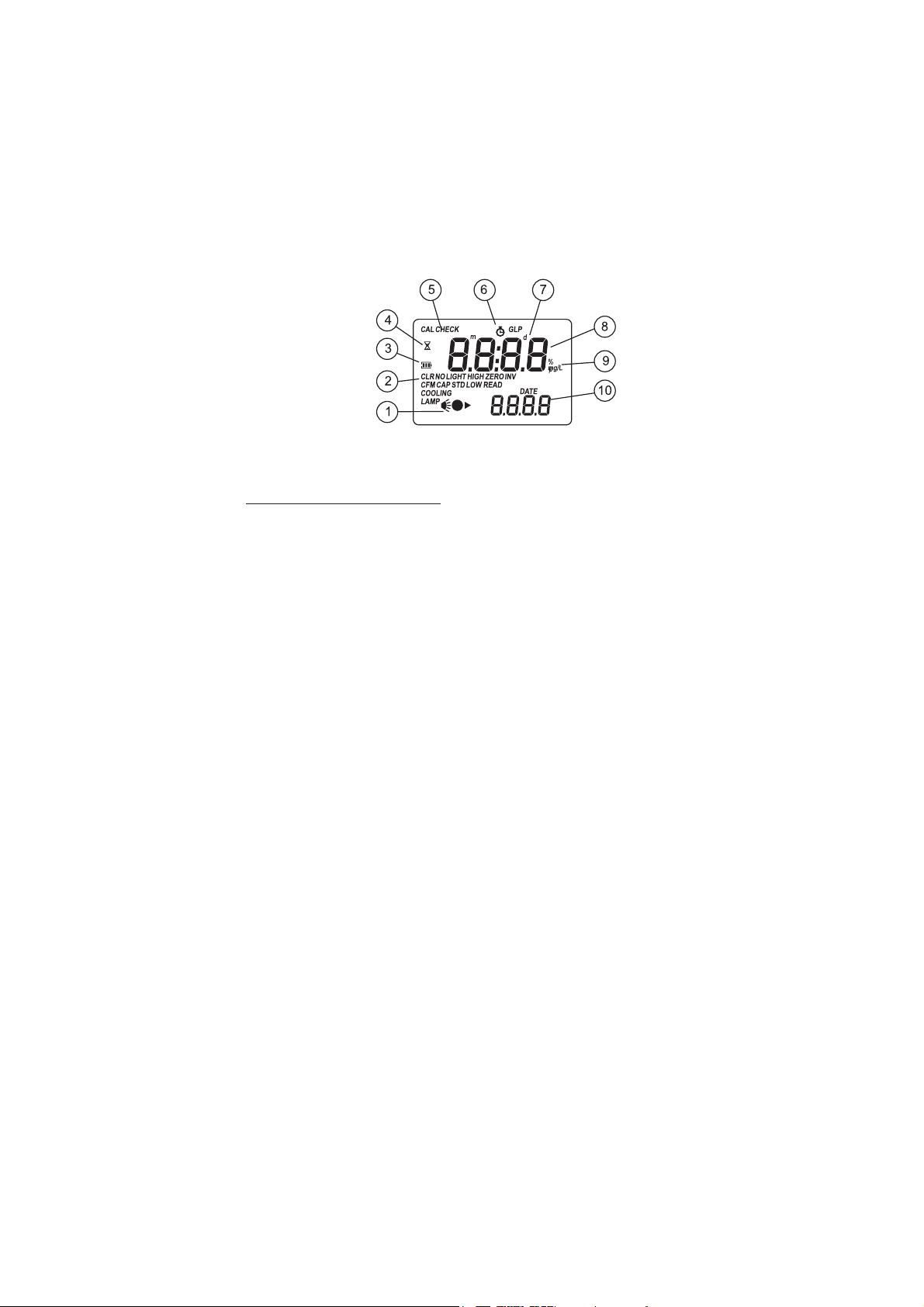
DISPLAY ELEMENTS DESCRIPTION
1) The measuring scheme (lamp, cuvette, detector), appears during different phases of zero or
reading measurement
2) Error messages and warnings
3) The battery icon indicates the charge state of the battery
4) The hourglass appears when an internal check is in progress
5) Status messages
6) The chronometer appears when the reaction timer is running
7) The month, day and date icons appear when a date is displayed
8) Four digit main display
9) Measuring units
10) Four digit secondary display
11
Page 12

ERRORS AND WARNINGS
The instrument shows clear messages when erroneous condition appears. Messages are also displayed
when the obtained values are outside expected range. The beeper is playing a beep on errors.
a) on zero reading
Light High: There is too much light to perform a measurement.
Please check the preparation of the zero cuvette.
Light Low: There is not enough light to perform a measurement.
Please check the preparation of the zero cuvette.
No Light: The instrument cannot adjust the light level. Please
check that the sample does not contain any debris.
b) on sample reading
Inverted cuvettes: The sample and the zero cuvette are inverted.
Zero: A zero reading was not taken. Follow the instructions of
the measurement procedure for zeroing the meter.
Under Range: A blinking “0.00” indicates that the sample
absorbs less light than the zero reference. Check the procedure
and make sure you use the same cuvette for reference (zero) and
measurement.
12
Page 13

c) during calibration procedure
d) other errors and warnings
Over Range: A flashing value of the maximum concentration
indicates an over range condition. The concentration of the
sample is beyond the programmed range: dilute the sample and
re-run the test.
Standard Low: The standard reading is less than expected.
Standard High: The standard reading is higher than expected.
Cap error: Appears when external light enters in the analysis
cell. Assure that the cuvette cap is present.
Cooling lamp: The instrument waits for the lamp to cool down.
Battery low: The battery must be replaced soon.
Dead battery: This indicates that the battery is dead and must
be replaced. Once this indication is displayed, normal operation
of the instrument will be interrupted. Change the battery and
restart the meter.
13
Page 14

GENERAL TIPS FOR AN ACCURATE MEASUREMENT
The instructions listed below should be carefully followed during testing to ensure best accuracy.
• Color or suspended matter in large amounts may cause
interference, therefore these should be removed by
treatment with active carbon and by prior filtration.
• For a correct filling of the cuvette: the liquid in the
cuvette forms a concavity on the top; the bottom of this
concavity must be at the same level of the 10 mL mark.
• Proper use of the powder reagent packet:
(a) use scissors to open the powder packet;
(b) push the edges of the packet to form a spout;
(c) pour out the content of the packet.
• Proper use of dropper:
(a) to get good reproducible results, tap the dropper on the table for several times and wipe
the outside of the dropper with a cloth.
(b) always keep the dropper bottle in a vertical position while dosing the reagent.
(a) (b)
14
Page 15

• It is important that the sample does not contain any debris.
This would corrupt the reading.
• Each time the cuvette is used, the cap must be tightened to
the same degree.
• Whenever the cuvette is placed into the measurement cell,
it must be dry outside, and completely free of fingerprints,
oil or dirt. Wipe it thoroughly with HI 731318 or a
lint-free cloth prior to insertion.
• Shaking the cuvette can generate bubbles in the sample, causing higher readings. To obtain
accurate measurements, remove such bubbles by swirling or by gently tapping the cuvette.
• Do not let the reacted sample stand too long after reagent is added, or accuracy will be lost.
• It is possible to take multiple readings in a row, but it is recommended to take a new zero
reading for each sample and to use the same cuvette for zeroing and measurement.
• After the reading it is important to discard immediately the sample, otherwise the glass
might become permanently stained.
• All the reaction times reported in this manual are referred to 20°C (68°F). As a general rule
of thumb, they should be doubled at 10°C (50°F) and halved at 30°C (86°F).
• In order to maximize accuracy, prior to a measurement follow the validation procedure to
be sure that the instrument is properly calibrated. If necessary, calibrate the instrument.
STARTUP
Prepare the instrument for measurement as follows:
• Unpack the instrument by removing the dust protection sleeve from the instrument cuvette
holder.
• Place the battery in the instrument as described in the “BATTERY REPLACEMENT” chapter.
• Place the instrument on a flat table.
• Do not place the instrument under direct sun light.
15
Page 16

RANGE SELECTION
The HI 96101 can measure pH when range P1 is selected, Free Chlorine when range P2 is
selected, Total Chlorine when range P3, Cyanuric Acid when range P4, Iodine when range P5,
Bromine when range P6, Iron LR when range P7 are selected. To change the active range follow
the procedure:
• Turn the meter on by pressing ON/OFF. The
display briefly shows all tags on.
• After startup, the range identification number is
displayed on the secondary LCD as P1, P2, P3,
P4, P5, P6 or P7.
Code Parameter
P1 pH
P2 Free Chlorine
P3 Total Chlorine
P4 Cyanuric Acid
P5 Iodine
P6 Bromine
P7 Iron LR
• Press RANGE/GLP/ to change the range.
The range can be changed any time when the
instrument is in
The selected range is memorized and the selection remaines unchanged at power off or when
the battery is removed.
measurement mode
.
MEASUREMENT PROCEDURE
To compensate the meter for the sample turbidity or color, the measurement takes place in two
phases. First, the meter is zeroed using the unreacted sample. After the reagents are added the
reacted sample is measured.
Important note: Free and Total Chlorine have to be measured separately with fresh unreacted
samples if both values are requested.
• Turn the meter on by pressing ON/OFF.
The display briefly shows all tags on.
16
Page 17

• When the beeper sounds briefly and the
LCD displays dashes, the meter is ready.
The blinking “ZERO” indicates that the
instrument needs to be zeroed first.
Note: Pay attention that the selected range
is the one desired to run measurements.
If not, change the range following the
instructions from Range Selection.
pH MEASUREMENT
• Fill the cuvette with 10 mL of unreacted
sample, up to the mark, and replace the
cap.
• Place the cuvette into the cuvette holder
and ensure that the notch on the cap is
positioned securely into the groove.
• Press ZERO/CFM and the lamp, cuvette
and detector icons will appear on the
display, depending on the measurement
phase.
• After a few seconds, the display will
show “-0.0-”. The meter is now zeroed
and ready for measurement.
• Remove the cuvette and add 5 drops of
the HI 93710-0 Phenol Red Indicator.
Replace the cap and shake gently the
solution.
• Replace the cuvette into the cuvette holder
and ensure that the notch on the cap is
positioned securely into the groove.
17
Page 18

• Press READ/ /TIMER. The lamp, cuvette
and detector icons will appear on the
display, depending on the measurement
phase.
• The instrument directly displays the
measured pH value on the Liquid Crystal
Display.
FREE CHLORINE MEASUREMENT
• Fill the cuvette up to the mark with 10
mL of unreacted sample and replace the
cap.
• Place the cuvette into the holder and ensure that the notch on the cap is positioned
securely into the groove.
• Press ZERO/CFM and the lamp, cuvette
and detector icons will appear on the
display, depending on the measurement
phase.
• After a few seconds, the display will
show “-0.0-”. The meter is now zeroed
and ready for measurement.
• Remove the cuvette.
• Add the content of one packet of
HI 93701-0 reagent. Replace the cap
and shake gently for 20 seconds (or
2 minutes in case of seawater analysis).
18
Page 19

• Replace the cuvette into the cuvette holder
and ensure that the notch on the cap is
positioned securely into the groove.
• Press and hold READ/ /TIMER for three
seconds. The display will show the
countdown prior to measurement. An
audible “beep” indicates the end of the
countdown period.
• Alternatively, wait for one minute and
just press READ/ /TIMER. In both
cases, the lamp, cuvette and detector
icons will appear on the display, depending on the measurement phase.
• The instrument directly displays
concentration in mg/L of free chlorine on
the Liquid Crystal Display.
INTERFERENCES
Interference may be caused by:
Bromine
Iodine
Chlorine Dioxide
Ozone
Oxidized manganese and Chromium
In case of water with hardness greater than 500 mg/L CaCO3, shake the sample for approximately
1 minute after adding the reagent.
In case of water with alkalinity greater than 250 mg/L CaCO3 or acidity greater than 150 mg/L
CaCO3, the color of the sample could disappear or develop only partially. To resolve this,
neutralize the sample with diluted HCl or NaOH.
19
Page 20

TOTAL CHLORINE MEASUREMENT
• Fill the cuvette up to the mark with 10
mL of unreacted sample and replace the
cap.
• Place the cuvette into the holder and ensure that the notch on the cap is positioned
securely into the groove.
• Press ZERO/CFM and the lamp, cuvette
and detector icons will appear on the
display, depending on the measurement
phase.
• After a few seconds, the display will
show “-0.0-”. The meter is now zeroed
and ready for measurement.
• Remove the cuvette and add one packet
of HI 93711-0 reagent. Replace the cap
and shake gently for 20 seconds (or
2 minutes in case of seawater analysis).
• Replace the cuvette into the cuvette holder
and ensure that the notch on the cap is
positioned securely into the groove.
• Press and hold READ/ /TIMER for
three seconds. The display will show
the countdown prior to measurement. An
audible “beep” indicates the end of the
countdown period.
20
Page 21

• Alternatively, wait for 2 minutes and 30
seconds and just press READ/ /TIMER.
In both cases, the lamp, cuvette and
detector icons will appear on the display,
depending on the measurement phase.
• The instrument directly displays
concentration in mg/L of total chlorine
on the Liquid Crystal Display.
INTERFERENCES
Interference may be caused by:
Bromine, Iodine, Chlorine Dioxide, Ozone, Oxidized manganese and Chromium.
In case of water with hardness greater than 500 mg/L CaCO3, shake the sample for approximately
1 minute after adding the reagent.
In case of water with alkalinity greater than 250 mg/L CaCO3 or acidity greater than 150 mg/L
CaCO3, the color of the sample could disappear or develop only partially. To resolve this,
neutralize the sample with diluted HCl or NaOH.
CYANURIC ACID MEASUREMENT
• Fill the cuvette with 10 mL of unreacted
sample, up to the mark, and replace the
cap.
• Place the cuvette into the cuvette holder
and ensure that the notch on the cap is
positioned securely into the groove.
• Press ZERO/CFM and the lamp, cuvette
and detector icons will appear on the
display, depending on the measurement
phase.
• After a few seconds, the display will
show “-0.0-”. The meter is now zeroed
and ready for measurement.
21
Page 22

• Fill a beaker up to the 25 mL mark with
the sample, add the content of one packet
of HI 93722-0 reagent and swirl gently
to mix. This is the reacted sample.
• Fill a second cuvette with 10 mL of the
reacted sample, up to the mark, and
replace the cap.
• Place the second cuvette into the cuvette
holder and ensure that the notch on the
cap is positioned securely into the groove.
• Press and hold READ/ /TIMER for three
seconds. The display will show the
countdown prior to measurement. An
audible “beep” indicates the end of the
countdown period.
• Alternatively, wait for 45 seconds then
just press READ/ /TIMER. In both
cases, the lamp, cuvette and detector
icons will appear on the display,
depending on the measurement phase.
• At the end of measurement, the
instrument directly displays concentration
in mg/L of cyanuric acid on the LCD.
22
Page 23

IODINE MEASUREMENT
• Fill the cuvette with 10 mL of unreacted
sample, up to the mark, and replace the
cap.
• Place the cuvette into the cuvette holder
and ensure that the notch on the cap is
positioned securely into the groove.
• Press ZERO/CFM and the lamp, cuvette
and detector icons will appear on the
display, depending on the measurement
phase.
• After a few seconds, the display will
show “-0.0-”. The meter is now zeroed
and ready for measurement.
• Remove the cuvette.
• Add the content of one packet of
HI 93718-0 Iodine reagent. Replace the
cap and shake gently for about 20 seconds
to dissolve most of the reagent.
• Replace the cuvette into the cuvette holder
and ensure that the notch on the cap is
positioned securely into the groove.
• Press and hold READ/ /TIMER for three
seconds. The display will show the
countdown prior to measurement. An
audible “beep” indicates the end of the
countdown period.
23
Page 24

• Alternatively, wait for 2 minutes and 30
seconds then just press READ/ /TIMER.
In both cases, the lamp, cuvette and
detector icons will appear on the display,
depending on the measurement phase.
• At the end of measurement, the instrument
directly displays concentration in mg/L of
iodine on the LCD.
INTERFERENCES
Bromine
Chlorine
Ozone
Oxidized forms of chromium and manganese
In case of water with alkalinity greater than 250 mg/L CaCO3 or acidity greater than 150 mg/L
CaCO3, the color of the sample could disappear or develop only partially. To resolve this,
neutralize the sample with diluted HCl or NaOH.
In case of water with hardness greater than 500 mg/L CaCO3, shake the sample for approximately
2 minutes after adding the reagent.
BROMINE MEASUREMENT
• Fill the cuvette with 10 mL of unreacted
sample, up to the mark, and replace the
cap.
• Place the cuvette into the cuvette holder
and ensure that the notch on the cap is
positioned securely into the groove.
• Press ZERO/CFM and the lamp, cuvette
and detector icons will appear on the
display, depending on the measurement
phase.
• After a few seconds, the display will
show “-0.0-”. The meter is now zeroed
and ready for measurement.
24
Page 25

• Remove the cuvette.
• Add the content of one packet of
HI 93716-0 Bromine reagent. Replace
the cap and shake gently for about
20 seconds to dissolve most of the
reagent.
• Replace the cuvette into the cuvette holder
and ensure that the notch on the cap is
positioned securely into the groove.
• Press and hold READ/ /TIMER for three
seconds. The display will show the
countdown prior to measurement. An
audible “beep” indicates the end of the
countdown period.
• Alternatively, wait for 2 minutes and 30
seconds then just press READ/ /TIMER.
In both cases, the lamp, cuvette and
detector icons will appear on the display,
depending on the measurement phase.
• At the end of measurement, the instrument
directly displays concentration in mg/L of
bromine on the LCD.
INTERFERENCES
Chlorine
Iodine
Ozone
Oxidized forms of chromium and manganese
In case of water with alkalinity greater than 250 mg/L CaCO3 or acidity greater than 150 mg/L
CaCO3, the color of the sample could disappear or develop only partially. To resolve this,
neutralize the sample with diluted HCl or NaOH.
In case of water with hardness greater than 500 mg/L CaCO3, shake the sample for approximately
1 minute after adding the reagent.
25
Page 26

IRON LR MEASUREMENT
12
3
6
9
30"
12
3
6
9
30"
• Fill one graduating mixing cylinder up to the 25
mL mark with deionized water.
• Add the content of one packet of HI 93746-0
TPTZ reagent, close the cylinder and shake
vigorously for 30 seconds. This is the blank.
• Fill the cuvette with 10 mL of the blank up to the
mark and replace the cap.
• Place the cuvette into the cuvette holder and ensure
that the notch on the cap is positioned securely
into the groove.
• Press ZERO/CFM and the lamp, cuvette and
detector icons will appear on the display, depending
on the measurement phase.
• After a few seconds, the display will show “-0.0-”.
The meter is now zeroed and ready for measurement.
25mL25mL
25mL
25mL25mL
• Remove the cuvette.
• Fill another graduated mixing cylinder up to the
25 mL mark with the sample.
• Add the content of one packet of HI 93746-0
TPTZ reagent, close the cylinder and shake vigorously for 30 seconds. This is the reacted sample.
• Fill a cuvette with 10 mL of the reacted sample up
to the mark and replace the cap.
26
25mL25mL
25mL
25mL25mL
Page 27

• Place the cuvette into the cuvette holder and
ensure that the notch on the cap is positioned
securely into the groove.
• Press and hold READ/ /TIMER for three
seconds. The display will show the countdown
prior to measurement. An audible “beep”
indicates the end of the countdown period.
• Alternatively, wait for 30 seconds then just
press READ/ /TIMER. In both cases, the
lamp, cuvette and detector icons will appear
on the display, depending on the measurement
phase.
• At the end of measurement, the instrument
directly displays concentration in mg/L of
iron LR on the LCD.
INTERFERENCES
Interference may be caused by:
Cadmium above 4.0 mg/L; Chromium
3+
above 0.25 mg/L; Chromium
6+
above 1.2 mg/L;
Cobalt above 0.05 mg/L; Copper above 0.6 mg/L; Cyanide above 2.8 mg/L; Manganese above
50.0 mg/L; Mercury above 0.4 mg/L; Molybdenum above 4.0 mg/L; Nickel above 1.0 mg/L;
Nitrite ion above 0.8 mg/L.
Sample pH should be between 3 and 4 to avoid developed color to fade or turbidity formation.
27
Page 28

VALIDATION PROCEDURE
Use the validation procedure to ensure that the instrument is properly calibrated.
Warning: Do not validate the instrument with any standard solutions other than the Hanna CAL
CHECKTM Standards, otherwise erroneous results will be obtained.
Note: The validation is performed only for the selected parameter. For full validation of the
instrument, the following procedure must be performed for each parameter.
• Turn the meter on by pressing ON/OFF.
• When the beeper sounds briefly and the
LCD displays dashes, the meter is ready.
• Place the CAL CHECKTM Standard
Cuvette A into the cuvette holder and
ensure that the notch on the cap is
positioned securely into the groove.
• Press ZERO/CFM and the lamp, cuvette
and detector icons will appear on the display,
depending on the measurement phase.
• After a few seconds, the display will
show “-0.0-”. The meter is now zeroed
and ready for validation.
• Remove the cuvette.
• Place the corresponding CAL CHECK
Standard Cuvette B into the cuvette holder:
pH: B, HI 96710-11
Free Chlorine: B, HI 96701-11
Total Chlorine: B, HI 96711-11
Cyanuric Acid: B, HI 96722-11
Iodine: B, HI 96718-11
Bromine: B, HI 96716-11
Iron LR: B, HI 96746-11
Ensure that the notch on the cap is
positioned securely into the groove.
• Press CAL CHECK and the lamp, cuvette
and detector icons together with “CAL
CHECK” will appear on the display,
depending on the measurement phase.
• At the end of the measurement the
display will show the validation standard
value.
TM
28
Page 29

The reading should be within specifications as reported in the CAL CHECKTM Standard
Certificate. If the value is found out of the specifications, please check that the cuvettes are free
of fingerprints, oil or dirt and repeat validation. If results are still found out of specifications,
then recalibrate the instrument.
CALIBRATION PROCEDURE
Note: It is possible to interrupt calibration procedure at any time by pressing CAL CHECK or
ON/OFF keys.
Warning: Do not calibrate the instrument with standard solutions other than the HANNA CAL
CHECKTM Standards, otherwise erroneous results will be obtained.
When calibrating, only the selected range is affected.
• Turn the meter on by pressing ON/OFF. When
the beeper sounds briefly and the LCD displays
dashes, the meter is ready.
• Press and hold CAL CHECK for three seconds to
enter
calibration mode
“CAL” during calibration procedure. The blinking
“ZERO” asks for instrument zeroing.
• Place the CAL CHECKTM Standard Cuvette A into
the cuvette holder and ensure that the notch on
the cap is positioned securely into the groove.
. The display will show
• Press ZERO/CFM and the lamp, cuvette and
detector icons will appear on the display,
depending on the measurement phase.
• After a few seconds the display will show “-0.0-”.
The meter is now zeroed and ready for calibration.
The blinking “READ” asks for reading calibration
standard.
• Remove the cuvette.
29
Page 30

• Place the corresponding CAL CHECKTM Standard
Cuvette B into the cuvette holder:
pH: B, HI 96710-11
Free Chlorine: B, HI 96701-11
Total Chlorine: B, HI 96711-11
Cyanuric Acid: B, HI 96722-11
Iodine: B, HI 96718-11
Bromine: B, HI 96716-11
Iron LR: B, HI 96746-11
Ensure that the notch on the cap is positioned
securely into the groove.
• Press READ/ /TIMER and the lamp, cuvette
and detector icons will appear on the display,
depending on the measurement phase.
• After measurement the instrument will show for
three seconds the CAL CHECKTM Standard value.
Note: If the display shows “STD HIGH”, the
standard value was too high. If the display
shows “STD LOW”, the standard value was
too low. Verify that all CAL CHECK
Standards Cuvettes, A and B are free from
fingerprints or dirt and that they are inserted
correctly.
TM
• Then the date of the last calibration (e.g.:
”01.08.2009”) appears on the display, or
“01.01.2009” if the factory calibration was
selected before. In both cases the year number
is blinking, ready for date input.
DATE INPUT
• Press RANGE/GLP/ to edit the desired year
(2009-2099). If the key is kept pressed, the
year number is automatically increased.
• When the correct year has been set, press
ZERO/CFM or READ/ /TIMER to confirm.
Now the display will show the month blinking.
30
or
Page 31

• Press RANGE/GLP/ to edit the desired
month (01-12). If the key is kept pressed,
the month number is automatically increased.
• When the correct month has been set, press
ZERO/CFM or READ/ /TIMER to confirm.
Now the display will show the day blinking.
• Press RANGE/GLP/ to edit the desired
day (01-31). If the key is kept pressed, the
day number is automatically increased.
Note: It is possible to change the editing from
day to year and to month by pressing
READ/ /TIMER.
• Press ZERO/CFM to save the calibration date.
• The instrument displays “Stor” for one second
and the calibration is saved.
or
• The instrument will return automatically to
measurement mode
the LCD.
by displaying dashes on
31
Page 32

GLP
In the GLP mode, the last user calibration date can be verified and the factory calibration can be
restored.
LAST CALIBRATION DATE
To display the calibration date:
• Press and hold for three seconds
RANGE/GLP/ to enter
the selected range the calibration month
and day will appear on the main display
and the year on the secondary display.
• If no calibration was performed, the
factory calibration message, “F.CAL” will
appear on the main display and the
instrument returns to
after three seconds.
FACTORY CALIBRATION RESTORE
It is possible to delete the calibration and
restore factory calibration.
GLP mode
. For
measurement mode
• Press and hold for three seconds
RANGE/GLP/ to enter
the selected range.
• Press READ/ /TIMER to enter in the
factory calibration restore screen. The
instrument asks for confirmation of user
calibration delete.
• Press ZERO/CFM to restore the factory
calibration or press RANGE/GLP/ again
to abort factory calibration restore.
• The instrument briefly indicates “donE”
upon restoration of factory calibration prior
to returning to
measurement mode
GLP mode
.
for
32
Page 33

BATTERY MANAGEMENT
To save battery, the instrument shuts down after 10 minutes of non-use in
and after 1 hour of non-use in
If a valid measurement was displayed before
auto-shut off, the value is displayed when
the instrument is switched on. The blinking
“ZERO” means that a new zero has to be
performed.
One fresh battery lasts for around 750 measurements, depending on the light level.
The remaining battery capacity is evaluated at the instrument startup and after each measurement.
The instrument displays a battery indicator with three levels as follows:
• 3 lines for 100 % capacity
• 2 lines for 66 % capacity
• 1 line for 33 % capacity
• Battery icon blinking if the capacity is under 10 %.
If the battery is empty and accurate measurements can’t be taken anymore, the instrument
shows “dEAd bAtt” and turns off.
To restart the instrument, the battery must be replaced with a fresh one.
calibration mode.
measurement mode
BATTERY REPLACEMENT
To replace the instrument’s battery, follow the steps:
• Turn the instrument off by pressing ON/OFF.
• Turn the instrument upside down and remove the battery cover by turning it counterclockwise.
• Extract the battery from its location and replace it with a fresh one.
• Insert back the battery cover and turn it clockwise to close.
33
Page 34

ACCESORIES
REAGENT SET
HI 93701-01 Reagents for 100 free chlorine tests
HI 93701-03 Reagents for 300 free chlorine tests
HI 93710-01 Reagents for 100 pH tests
HI 93710-03 Reagents for 300 pH tests
HI 93711-01 Reagents for 100 total chlorine tests
HI 93711-03 Reagents for 300 total chlorine tests
HI 93716-01 Reagents for 100 bromine tests
HI 93716-03 Reagents for 300 bromine tests
HI 93718-01 Reagents for 100 iodine tests
HI 93718-03 Reagents for 300 iodine tests
HI 93722-01 Reagents for 100 cyanuric acid tests
HI 93722-03 Reagents for 300 cyanuric acid tests
HI 93746-01 Reagents for 50 iron low range tests
HI 93746-03 Reagents for 100 iron low range tests
OTHER ACCESORIES
HI 96701-11 CAL CHECKTM Standard Cuvettes for Free Chlorine (1 set)
HI 96710-11 CAL CHECKTM Standard Cuvettes for pH (1 set)
HI 96711-11 CAL CHECKTM Standard Cuvettes for Total Chlorine (1 set)
HI 96716-11 CAL CHECKTM Standard Cuvettes for Bromine (1 set)
HI 96718-11 CAL CHECKTM Standard Cuvettes for Iodine (1 set)
HI 96722-11 CAL CHECKTM Standard Cuvettes for Cyanuric Acid (1 set)
HI 96746-11 CAL CHECKTM Standard Cuvettes for Iron (1 set)
HI 721310 9V battery (10 pcs.)
HI 731318 Tissue for wiping cuvettes (4 pcs.)
HI 731331 Glass cuvettes (4 pcs.)
HI 731335 Caps for cuvettes (4 pcs.)
HI 93703-50 Cuvettes cleaning solution (230 mL)
34
Page 35

WARRANTY
HI 96101 is warranted for two years against defects in workmanship and materials when used
for its intended purpose and maintained according to the instructions.
This warranty is limited to repair or replacement free of charge.
Damages due to accident, misuse, tampering or lack of prescribed maintenance are not covered.
If service is required, contact your dealer. If under warranty, report the model number, date of
purchase, serial number and the nature of the failure. If the repair is not covered by the warranty,
you will be notified of the charges incurred.
If the instrument is to be returned to Hanna Instruments, first obtain a Returned Goods
Authorization Number from the Customer Service Department and then send it with shipment
costs prepaid. When shipping any instrument, make sure it is properly packaged for complete
protection.
To validate your warranty, fill out and return the enclosed warranty card within 14 days from the
date of purchase.
Recommendations for Users
Before using these products, make sure that they are entirely suitable for your specific application and for the environment in
which they are used.
Operation of these instruments may cause unacceptable interferences to other electronic equipments, this requiring the operator
to take all necessary steps to correct interferences.
Any variation introduced by the user to the supplied equipment may degrade the instruments' EMC performance.
To avoid damages or burns, do not put the instrument in microwave oven. For yours and the instrument safety do not use or
store the instrument in hazardous environments.
Hanna Instruments reserves the right to modify the design, construction and appearance of
its products without advance notice.
35
Page 36

Hanna Instruments Inc.
Highland Industrial Park
584 Park East Drive
Woonsocket, RI 02895 USA
Technical Support for Customers
Tel. (800) 426 6287
Fax (401) 765 7575
E-mail tech@hannainst.com
www.hannainst.com
Local Sales and Customer Service Office
Printed in EUROPE
(ROMANIA)
MAN96101 10/10
36
 Loading...