

Page 1

Instruction Manual
HI933300
HI933301
Portable Microprocessor
Printing and Logging
Multi-Range
Conductivity Meters
These Instruments are in Compliance with the CE Directives
http://www.hannainst.com
Page 2

Dear Customer,
Thank you for choosing a Hanna Instruments
Product.
Please read this instruction manual carefully
before using the instrument.
This manual will provide you with all the necessary information for the correct use of the
instrument, as well as a precise idea of its
versatility in a wide range of applications.
These instruments are in compliance with
directives EN 50081-1 and 50082-1.
TABLE OF CONTENTS
Preliminary Examination............................. 1
General Description ................................... 1
LCD Display Functional Description .......... 3
Functional Description HI 76302W
Conductivity Probe ..................................... 3
Functional Description HI 933300 .............. 4
Functional Description HI 933301 .............. 5
Specifications ............................................. 6
Operational Guide ...................................... 7
Conductivity Calibration............................ 18
Conductivity Versus Temperature Chart.. 26
Temperature Calibration........................... 27
Printing/Recording with HI933301............ 30
Printing/Logging with HI933300 ............... 33
Data Transfer to PC................................. 42
Fault Functions......................................... 44
Memory Organization (HI933300)............ 45
Printer Maintenance ................................. 46
Probe Maintenance .................................. 48
Battery Replacement................................ 49
Accessories.............................................. 50
Warranty................................................... 52
CE Declaration of Conforminty ................ 53
ISO 9000 Certified
Company since 1992
Page 3

PRELIMINARY EXAMINATION
Remove the instrument from the packing material and examine it to make sure that no
damage has occurred during shipping. If there
is any damage, notify your Dealer.
Each printing/logging conductivity meter is supplied complete with:
• HI 76302W Conductivity Probe with
1 m (3.3') screened cable
• AA size Alkaline Batteries (4 pcs)
• Paper roll (10 pcs)
• Rugged carrying case
Note: Save all packing materials until you are
sure that the instrument functions correctly. All defective items must be returned in the original packaging together
with the supplied accessories.
GENERAL DESCRIPTION
The HI933300 and HI933301 are multirange
conductivity meters equipped with printer and
datalogger (HI933300 only).
The measurement interval is user-selectable
from 1 to 180 minutes, and the temperature
coefficient β can vary from 0.0 to 3.0%/°C.
These microprocessor-based meters provide
automatic calibration with 5 memorized values:
• 0 µS/cm (µmhoS/cm)
• 84 µS/cm (µmhoS/cm)
• 1413 µS/cm (µmhoS/cm)
• 12880 µS/cm (µmhoS/cm)
• 80000 µS/cm (µmhoS/cm).
This makes the calibration procedure extremely simple.
HI933300 can also log and directly print the
conductivity and temperature measurements.
1
Page 4

The stored data can be retrieved at a later
time for printing or can be transferred to a
computer through an optional HI9200 infrared
transmitter. The HI933300 will transfer the
data in seconds through the infrared lights
with no need for a cable between the transmitter and the meter.
The internal software allocates memory space
to store up to 8,000 readings.
The meters provide automatic temperature
compensation with the supplied HI76302W
4-ring probe with integrated temperature sensor. The sensors in the meter's probe utilize
the latest technology in conductivity measurement.
The four-ring potentiometric method incorporated into the probe has been proven to provide higher accuracy than the more common
amperometric method.
HI933300 and HI933301 have a range of 0 to
199900 µS/cm and can be used in any sample
from deionized water to brine.
The probe's stainless steel rings have a large
surface for better response and ease of cleaning.
The meters are equipped with an automatic
shut-off system and a 12VDC socket for maximum versatility in both laboratory and field
use.
Other features include: on-board time and
date, calibration factors stored in Eprom, automatic low battery alert system.
2
Page 5

LCD DISPLAY FUNCTIONAL DESCRIPTION
1
mS
2
LOG
INTV
LO BAT
1. Primary Display
2. Secondary Display
FUNCTIONAL DESCRIPTION HI 76302W
CONDUCTIVITY PROBE
1
2
3
4
1. Watertight Shielded Screened Cable
2. Air-Release Holes
3. PVC Protective Sleeve
4. 4 Stainless Steel Rings.
3
Page 6

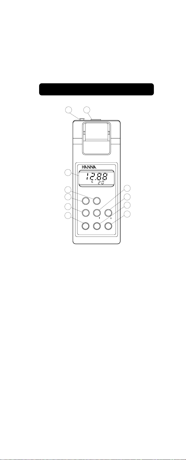
FUNCTIONAL DESCRIPTION HI 933300
1
3
4
5
6
7
2
LOG
HI 933300
MICROPROCESSOR LOGGING
CONDUCTIVITY METER
PRINT
PAPER
CAL
ALT
TIME
RANGE
mS
11
10
9
CFM
LOG
8
1. Power adapter plug
2. Conductivity probe socket
3. LCD display
4. PAPER key, to pull the paper and to
reset the printer
5. PRINT key, to obtain a printout
6. ALT key, Alternate Function key
7. RANGE key, to display the conductivity
or the temperature
8. LOG key, to enter the logging mode
9. TIME key, to display present time and
printing interval
10. CFM key, to confirm calibration data
11. CAL key, to enter or exit the calibration
mode.
4
Page 7
FUNCTIONAL DESCRIPTION HI 933301
1
3
4
5
6
7
2
LOG
HI 933301
MICROPROCESSOR PRINTING
CONDUCTIVITY METER
ON/OFF
PAPER
CAL
ALT
PRINT
RANGE
CFM
RECORD
mS
11
10
9
8
1. Power adapter plug
2. Conductivity probe socket
3. LCD display
4. PAPER key, to pull the paper and to
reset the printer
5. ON/OFF key, to turn the meter on or off
6. ALT key, Alternate Function key
7. RANGE key, to display the conductivity
or the temperature
8. RECORD key, to enter the recording mode
9. PRINT key, to obtain a printout
10. CFM key, to confirm calibration data
11. CAL key, to enter or exit the calibration
mode.
5
Page 8
Measurement
Range µS/cm
µS/cm
mS/cm
mS/cm
°C
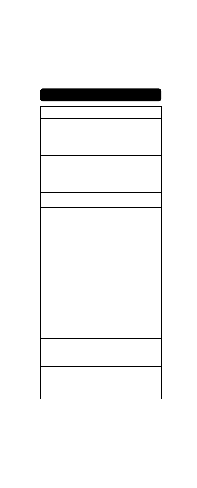
SPECIFICATIONS
HI 933300 & HI933301
0.0 to 150.0
150 to 1500
1.50 to 15.00
15.0 to 199.9
0.0 to 60.0
Resolution
Accuracy
(@20°C/68°F)
Typical EMC
Deviation
Calibration
Temperature
Compensation
Probe
Printer
Printing/Logging
interval
0.1 µS/cm, 1 µS/cm
0.01 mS/cm, 0.1 mS/cm, 0.1°C
±1% full scale; ±0.5°C
excluding probe error
±1% F.S
±0.5°C
Automatic 1, 2, 3, 4 or 5 points
at 0, 84, 1413, 12880,
80000 µS/cm
Automatic from 0 to 60 °C (32 to
140°F) with variable ß from 0.0
to 3.0%
HI76302W (included) detach-
able with 4 stainless steel AISI
316 rings and incorporated temperature sensor. Probe length is
120mm (4.8"), diameter is 20mm
(0.8"); screened cable length is
1 meter (3.3')
Low-power impact type-belt, 14
characters per line using 38 mm
plain paper
Selectable from 1, 2, 5, 10, 15,
30, 60, 120, 180 minutes
Battery Type
Life
Environment
Dimensions
Weight
4 x 1.5 volt AA size.
500 hours with 60' printing
interval. Power socket for
12VDC adapter
0 to 50°C (32 to 122°F), 95 %RH
196 x 80 x 57 mm
(7.7 x 3.1x 2.2")
425 g (15 oz.) instrument only
6
Page 9

OPERATIONAL GUIDE
INITIAL PREPARATION
Each meter is supplied complete with batteries. Remove
the back cover, unwrap the
batteries and install them while
paying attention to their polarity.
To prepare the instrument for
use, connect the probe to the
meter securely by aligning the
pins with the socket located
on the top of the instrument,
pushing the plug in and tightening the threaded ring.
Make sure that the sleeve is
properly inserted on the probe,
with the holes towards the top
of the probe (the end nearest
to the cable).
-
1.5V
+
-
1.5V
+
-
1.5V
1.5V
+
SCREW
+
POTS
-
To turn the HI933300 on,
press the RANGE key.
RANGE
To turn the HI933301 on,
press the ON/OFF key.
ON/OFF
The meter will display the clock time as 0:00
and a default sampling interval of 1 minute.
TIME
INTV
7
Page 10
To maximize battery life, the display is automatically switched off after 5 minutes of nonuse.
The meter continues to monitor (if in the logging or recording mode) conductivity and
temperature even when the
ON/OFF
display is off.
To revive the display, press
either the ON/OFF or the
RANGE key.
RANGE
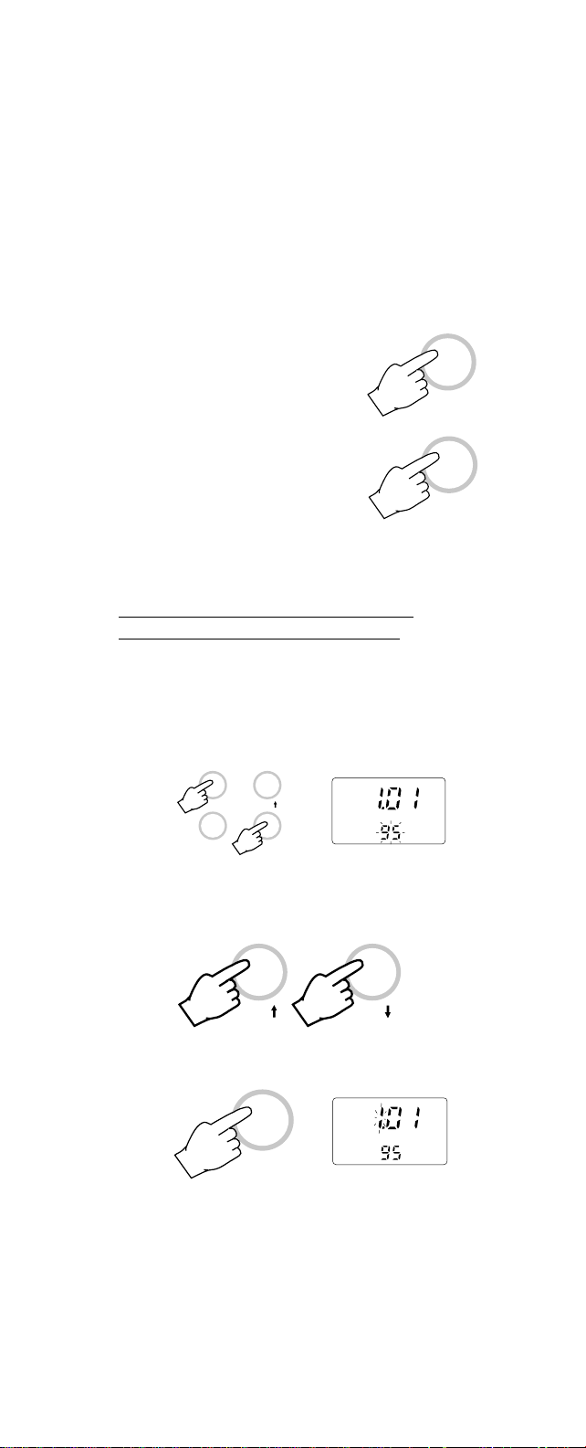
SETTING DATE/TIME/PRINTING
INTERVAL (for HI933300 only)
Press the ALT and the TIME keys simultaneously. The display will show the date setting. At the bottom of the display the year will
start blinking.
ALT
RANGE
CAL
TIME
DATE
Use the UP or DOWN arrow key to select
the year.
or
CAL CFM
When the correct year is selected, press the
TIME key once. The month will start blinking.
DATE
TIME
8
Page 11
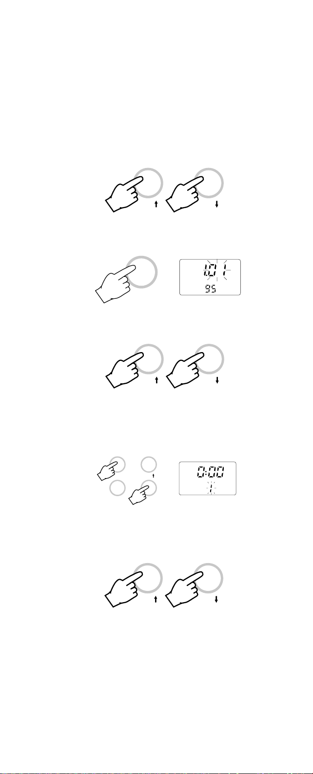
Select the month by using the UP or DOWN
arrow key.
or
CAL CFM
Press the TIME key. The day will start blinking.
DATE
TIME
Use the UP or DOWN arrow key to select
the correct day.
or
CAL CFM
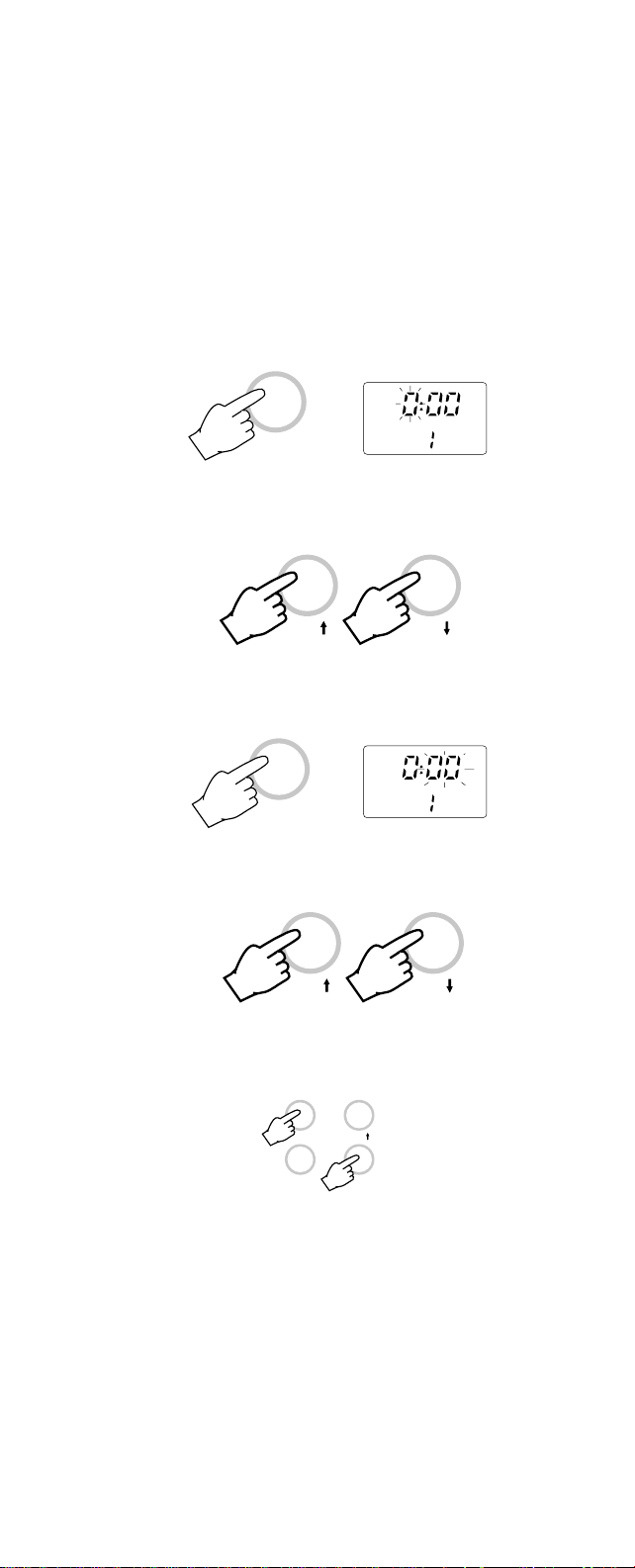
Press the ALT and the TIME keys simultaneously. The display will now show the time
and the printing interval will start blinking.
ALT
RANGE
CAL
TIME
TIME
INTV
The interval can be selected from 1, 2, 5, 10,
15, 30, 60, 120 or 180 minutes by using the
UP and DOWN arrow keys.
or
CAL CFM
9
Page 12
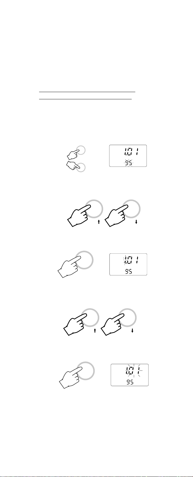
Once the desired interval is selected press
the TIME key once to set it. The hour will
start blinking.
TIME
TIME
INTV
To select the hour press the UP or DOWN
arrow key (24 hour clock).
or
CAL CFM
Press the TIME key once. The minutes will
start blinking.
TIME
TIME
Use the UP or DOWN arrow key to select
the minute.
INTV
or
CAL CFM
Press the ALT and the TIME keys to leave
this mode.
ALT
CAL
RANGE
The meter's time, date and interval are now
set and stored in the memory even when the
display is switched off.
TIME
10
Page 13

VIEWING TIME / DATE / CONDUCTIVITY /
TEMPERATURE (for HI933300 only)
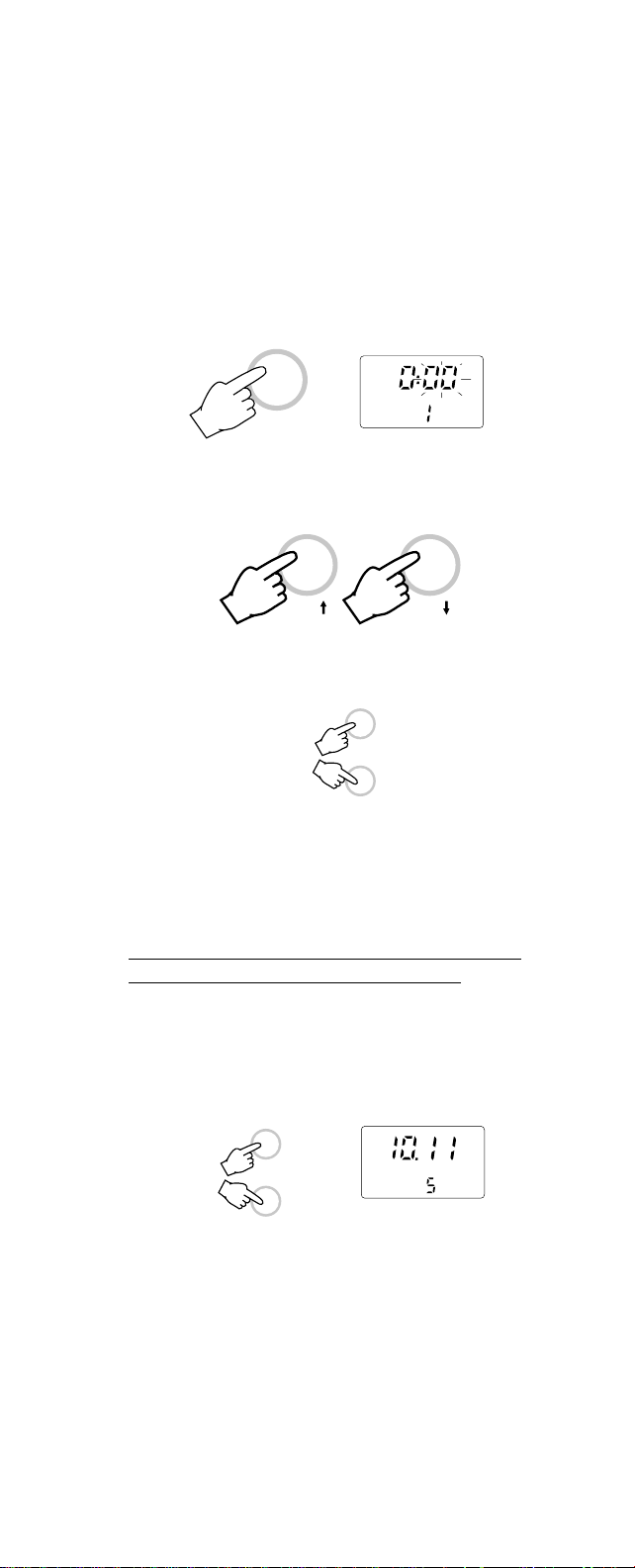
To view the time press the TIME key. This
also displays the selected interval time.
TIME
TIME
INTV
To view the date, press the UP arrow key
when the LCD is displaying the time.
DATE
CAL
To view the conductivity and temperature press
the RANGE key. Conductivity will be displayed on the primary display and temperature on the secondary (without decimal point).
mS
RANGE
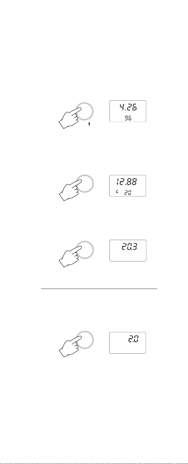
To view the temperature press the RANGE
key again. The temperature will be displayed
on the primary display with a decimal point.
°C
RANGE
11
Page 14
SETTING DATE/TIME/PRINTING
INTERVAL (for HI933301 only)
Press the ALT and the RANGE keys twice
simultaneously. The display will show the
date setting. At the bottom of the display the
year will start blinking.
ALT
RANGE
DATE
Use the UP or DOWN arrow key to select
the year.
or
CAL CFM
When the correct year is selected, press the
TIME key once. The month will start blinking.
DATE
RANGE
Select the month by using the UP or DOWN
arrow key.
or
CAL CFM
Press the RANGE key. The day will start
blinking.
DATE
RANGE
12
Page 15

Use the UP or DOWN arrow key to select
the correct day.
or
CAL CFM
Press the ALT and the RANGE keys simultaneously. The display will now show the time
and the printing interval will start blinking.
ALT
TIME
RANGE
INTV
The interval can be selected from 1, 2, 5, 10,
15, 30, 60, 120 or 180 minutes by using the
UP and DOWN arrow keys.
or
CAL CFM
Once the desired interval is selected press
the RANGE key once to set it. The hour will
start blinking.
TIME
RANGE
INTV
To select the hour press the UP or DOWN
arrow key (24 hour clock).
or
CAL CFM
13
Page 16
Press the RANGE key once. The minutes
will start blinking.
TIME
RANGE
INTV
Use the UP or DOWN arrow key to select
the minute.
or
CAL CFM
Press the ALT and the RANGE keys simultaneously to leave this mode.
ALT
RANGE
The meter's time, date and interval are now
set and stored in memory even when the
display is switched off.
VIEWING TIME / DATE / CONDUCTIVITY /
TEMPERATURE (for HI933301 only)
To view the time press the ALT and RANGE
keys simultaneously. This also displays the
selected interval time.
ALT
INTV
RANGE
TIME
14
Page 17
To view the date, press the UP arrow key
when the LCD is displaying the time.
DATE
CAL
To view the conductivity and temperature press
the RANGE key. Conductivity will be displayed on the primary display and temperature on the secondary (without decimal point).
mS
RANGE
To view the temperature press the RANGE
key again. The temperature will be displayed
on the primary display with a decimal point.
°C
RANGE
SETTING THE TEMPERATURE COEFFICIENT
Press the RANGE key until the display shows
the temperature coefficient setting.
%
RANGE
This value is adjustable from 0.0 to 3.0%/°C.
15
Page 18

Use the UP and the DOWN arrow key to
change the setting.
or
CAL CFM
TAKING CONDUCTIVITY MEASUREMENTS
Make sure that the meter has been calibrated before taking any measurements (see
page 18).
To take a measurement, place the probe
into the solution with the
holes completely submerged. Tap and stir the
probe to remove all air
bubbles that may be trapped
inside the PVC sleeve.
HI933300 and HI933301 are
auto-ranging conductivity meters, and the
reading automatically switches from one
resolution to the next, from pure water @
0.1µS/cm up to 199900µS/cm.
If the LCD displays four
dashes, the meter is out of
range.
HI76302W conductivity probe has a built-in
temperature sensor and automatically compensates for any temperature variation.
Wait for a few minutes for the temperature
sensor to attain thermal equilibrium with the
test solution before taking the measurement.
If the temperature of the conductivity probe
and the solution is of considerable difference,
a longer time should be allowed before taking
readings.
16
Page 19

Once the reading stabilizes
the measurement is complete.
mS
If further measurements are
desired, rinse the probe with
tap water and test the next sample.
Note: The probe body and sleeve are made
of PVC and are very susceptible to
damage due to temperatures exceeding 50°C (122°F).
If the probe is exposed to high temperature, the bond between the rings
and the probe body may become impaired and the probe will not function
properly, in which case it has to be
replaced.
TAKING TEMPERATURE MEASUREMENTS
Taking temperature measurement with
HI933300 and HI933301 is very easy.
Press the RANGE key until the display shows
the °C mode.
°C
RANGE
Simply immerse the probe
into the sample and allow the
reading to stabilize.
AFTER MEASUREMENTS
When all measurements are completed follow the probe maintenance procedure described at page 48.
17
Page 20

CONDUCTIVITY CALIBRATION
It is recommended that HI933300 and
HI933301 are calibrated frequently for great-
est accuracy, especially when used often or
in samples with widely differing conductivity
values. For best results choose conductivity
solutions that are closest in value to the
sample to be measured.
For accurate calibra-
RINSE CALIBRATION
tion, use two beakers for each solution: the first one for
rinsing the probe,
the second one for
calibration. In this way cross contamination
is minimized.
If possible, to minimize any EMC interferences, use plastic beakers for the solutions.
These meters can also be calibrated in air at
0.0µS/cm.
For example if your measurements are in the
2 to 20 mS/cm range you should use HI7030
or HI 8030 (12880µS/cm=12.88 mS/cm) conductivity calibration solution.
A complete list of all the Hanna Instruments
calibration solution is given in the Accessories section (see page 50).
Press the RANGE key to select the conductivity measurement mode.
RANGE
Ensure that the probe is connected to the meter securely.
Insert the probe into the PVC sleeve with the
holes towards the top (the end nearest to the
cable) of the probe.
18
Page 21

PROCEDURE FOR OFFSET CALIBRATION
(at 0.0 µS/cm)
• To perform the Offset
calibration, dry the conductivity probe and leave
it in air.
• Press the ALT and the CAL keys simultaneously. The primary LCD display will blink
"0.0 µS" for about 10 seconds.
µS
ALT
CAL
• When "0.0 µS" stops blinking, the cali-
bration can be confirmed. Press the CFM
key to confirm the offset value.
µS
CFM
• If the input reading is out of the offset
range, an error message will show on the
secondary display "E0". Press the CAL
key to re-calibrate the value.
• If everything is satisfactory
the LCD will blink
"84.0 µS", expecting the
first calibration solution.
• Press the CAL key to exit
the calibration mode now.
19
CAL
µS
CAL
Page 22

PROCEDURE FOR SINGLE POINT
CALIBRATION WITH BUFFER SOLUTION
HI933300 and HI933301 have auto-buffer rec-
ognition: you can simply place the probe into
the type of buffer solution that you need to
calibrate and perform the single point calibration very quickly as described below.
Choose one of the following calibration solutions:
84.0 µS/cm (cal. solution HI7033/HI8033)
1413 µS/cm (cal. solution HI7031/HI8031)
12.88mS/cm(cal. solution HI7030/HI8030)
80.0 mS/cm(cal. solution HI7034/HI8034)
• Fill a beaker with conductivity calibration solution
(e.g. HI7030 or HI8030,
12.88mS/cm).
8 cm
(3¼")
• Press the RANGE key to
select the conductivity
measurement mode.
RANGE
• Dip the probe into the
sample. The level of solution must be higher than
the holes on the PVC
sleeve. Tap the probe repeatedly on the bottom of
the beaker and stir it to ensure that no air
bubbles are trapped inside the sleeve.
• Press the CAL key and the buffer value
will be blinking on the display (e.g.
12.88 mS/cm).
CAL
mS
20
Page 23

• When the buffer value stops blinking, indicating that the probe has stabilized, press
the CFM key to confirm the value.
mS
CFM
• Press the CAL key to exit the calibration
mode now.
CAL
PROCEDURE FOR A COMPLETE
CALIBRATION WITH 5 BUFFERS
HI933300 and HI933301 have 5 memorized
calibration values:
0.0 µS/cm (probe in air)
84.0 µS/cm (cal. solution HI 7033/HI8033)
1413 µS/cm (cal. solution HI 7031/HI8031)
12.88mS/cm(cal. solution HI7030/HI8030)
80.0 mS/cm(cal. solution HI 7034/HI8034)
These meters can be calibrated at all the
above five points as described below.
• To perform the Offset calibration, dry the conductivity probe and leave it in
air.
• Press the ALT and the CAL keys simultaneously. The primary LCD display will blink
"0.0 µS" for about 10 seconds.
CAL
ALT
21
µS
Page 24

• When "0.0 µS" stops blinking, the cali-
bration can be confirmed. Press the CFM
key to confirm the offset value.
µS
CFM
• If the input reading is out of the offset
range, "E0" as error message will appear
on the secondary display . Press the CAL
key to re-calibrate the value.
CAL
• If everything is satisfactory the LCD will blink
µS
"84.0 µS", expecting
the next calibration solution (HI7033 or
HI8033).
• Fill a beaker with HI7033
or HI8033 conductivity
3
3
0
I 7
H
calibration solution.
• Immerse the probe into
8 cm
(3¼")
the calibration solution.
The level of solution must be higher than
the holes on the PVC sleeve. Tap the
probe repeatedly on the bottom of the
beaker and stir it to ensure that no air
bubbles are trapped inside the sleeve.
• When the "84.0 µS" stops blinking, indi-
cating that the measurement has stabilized, press the CFM key again to confirm
the second point calibration.
µS
CFM
22
Page 25

• If the value is out of the slope range, an
"E1" error message will appear on the
secondary display. Press the CAL key to
re-calibrate the value.
CAL
• If everything is satisfactory the LCD will blink
µS
"1413 µS", expecting
the next calibration solution (HI7031 or
HI8031).
• Wait for 1 minute, then
HI 7031
immerse the probe into
the HI7031/HI8031 calibration solution. The
8 cm
(3¼")
level of solution must be
higher than the holes on the PVC sleeve.
Tap the probe repeatedly on the bottom of
the beaker and stir it to ensure that no air
bubbles are trapped inside the sleeve.
• When the "1413 µS" stops blinking, indi-
cating that the measurement has stabilized, press the CFM key again to confirm
the third calibration point.
µS
CFM
• If the value is out of the slope range, an
"E2" error message will appear on the
secondary display. Press the CAL key to
re-calibrate the value.
CAL
23
Page 26

• If everything is satisfactory the LCD will blink
mS
"12.88 mS", expecting
the next calibration solution (HI7030 or
HI8030).
• Wait for 1 minute, then
HI 7030
immerse the probe into
the HI7030/HI8030 calibration solution. The level
8 cm
(3¼")
of solution must be
higher than the holes on the PVC sleeve.
Tap the probe repeatedly on the bottom of
the beaker and stir it to ensure that no air
bubbles are trapped inside the sleeve.
• When the "12.88 mS" stops blinking,
indicating that the measurement has stabilized, press the CFM key again to confirm the fourth calibration point.
mS
CFM
• If the value is out of the slope range, an
"E3" error message will appear on the
secondary display. Press the CAL key to
re-calibrate the value.
• If everything is satisfactory the LCD will blink
"80.0 mS", expecting
the next calibration solution (HI7034 or HI8034)
• Wait for 1 minute, then
immerse the probe into
the HI7034/HI7034 calibration solution. The level
of solution must be higher
24
CAL
8 cm
(3¼")
mS
4
3
0
I 7
H
Page 27

than the holes on the PVC sleeve. Tap the
probe repeatedly on the bottom of the
beaker and stir it to ensure that no air
bubbles are trapped inside the sleeve.
• When the "80.0 mS" stops blinking,
indicating that the measurement has stabilized, press the CFM key again to confirm the fifth calibration point.
mS
CFM
• If the value is out of the slope range, an
"E4" error message will appear on the
secondary display. Press the CAL key to
re-calibrate the value.
CAL
• If everything is satisfactory the calibration
ends and the meter will return to the normal operational mode.
Note:
• If the instrument will not calibrate refer
to the Probe Maintenance and Cleaning section (see page 48).
• It is always possible to quit the calibration mode by pressing the CAL key.
CAL
25
Page 28

CONDUCTIVITY VERSUS
TEMPERATURE CHART
As shown in the chart below, temperature
has an effect on conductivity.
°C °F HI7030 HI7031 HI7033 HI7034 HI7035 HI7039
HI8030 HI8031 HI8033 HI8034 HI8035 HI8039
(µS/cm) (µS/cm) (µS/cm) (µS/cm) (µS/cm) (µS/cm)
0 32 7150 776 64 48300 65400 2760
5 41 8220 896 65 53500 74100 3180
10 50 9330 1020 67 59600 83200 3615
15 59 10480 1147 68 65400 92500 4063
16 60.8 10720 1173 70 67200 94400 4155
17 62.6 10950 1199 71 68500 96300 4245
18 64.4 11190 1225 73 69800 98200 4337
19 66.2 11430 1251 74 71300 100200 4429
20 68 11670 1278 76 72400 102100 4523
21 69.8 11910 1305 78 74000 104000 4617
22 71.6 12150 1332 79 75200 105900 4711
23 73.4 12390 1359 81 76500 107900 4805
24 75.2 12640 1386 82 78300 109800 4902
25 77 12880 1413 84 80000 111800 5000
26 78.8 13130 1440 86 81300 113800 5096
27 80.6 13370 1467 87 83000 115700 5190
28 82.4 13620 1494 89 84900 117700 5286
29 84.2 13870 1521 90 86300 119700 5383
30 86 14120 1548 92 88200 121800 5479
31 87.8 14370 1575 94 90000 123900 5575
HI933300 and HI933301 will always display
the value of the buffers at 25°C (77°F), e.g.
"1413 µS" using HI7031 or HI8031 as calibration solution.
26
Page 29

TEMPERATURE CALIBRATION
(for Technical Personnel only)
INITIAL PREPARATION
Prepare a container of ice and water and
another container with hot water (at a temperature of at least 50°C/122°F). Place insulation material around the containers to minimize temperature changes.
Use a ChecktempC or a calibrated thermometer with a resolution of 0.1° as reference
thermometer.
0 °C
(32 °F)
°C
50 °C
(122 °F)
°C
Note: After performing the following calibra-
tion, conductivity must be recalibrated.
PROCEDURE
• Press the RANGE key to select the temperature measurement mode (just temperature measurement on the primary display).
°C
RANGE
• Ensure that the probe is connected to the
meter securely by aligning the pins with
the socket, pushing the plug in and tightening the threaded ring. Insert the probe
27
Page 30

into the PVC sleeve with the holes towards
the top (the end nearest to the cable) of
the probe.
°
C
• Place the probe into the
container with ice and water (0.0°C/32°F).
0 °C
(32 °F)
• Press the CAL key. The secondary (lower)
display will blink "0" for about 30 seconds.
CAL
• When "0" stops blinking, the calibration
can be confirmed. Press the CFM key to
confirm the first value.
CFM
• If the value is out of the offset range, an
error message will show on the secondary
display "E1". Press the CAL key to recalibrate the value.
CAL
28
Page 31

• If everything is satisfactory
the LCD will blink "50"
expecting the second
buffer (50°C/122°F).
Note: if a single point cali-
bration is required,
press the CAL key
to leave the calibra-
CAL
tion mode now.
°C
• Place the probe into the
second container with hot
water (50°C/122°F).
50 °C
(122 °F)
• When "50" stops blinking, press the CFM
key again to confirm the second calibration point.
CFM
• If the value is out of the slope range, an
error message will show on the secondary
display "E2". Press the CAL key to recalibrate the value.
CAL
• If everything is satisfactory the temperature calibration is complete and the meter
will return to the normal operational mode.
29
Page 32

PRINTING/RECORDING WITH HI933301
To print the measured values
press the PRINT key.
The printout provides the following information:
PRINT
a- Running log number
b- Date (DD-MM-YY)
c - Time (HH-MM)
d- Conductivity value in µS/cm or mS/cm
e- Temperature in degrees Centigrade.
a
29-03-96
--01-*15.01
147.6 µS
25.1 ° C
b
c
d
e
RECORDING MODE (PROGRAMMED
PRINTOUTS)
Set the appropriate printing interval (see Operational Guide section on page 12).
Press the ALT and the
RECORD keys simulta-
ALT CAL CFM
neously to enter the recording mode.
PRINT RECORDRANGE
The log number will appear
for a few seconds on the
display to indicate the cor-
LOG INTV
rect operational mode.
The meter will print the measurement taken
at that moment and will continue to print
according to the set interval until the recording function is stopped (see below).
30
Page 33

Each printout provides the following information:
a- Running log number.
b- Running sample number in that particular
log.
c- Date (DD-MM-YY)
d- Printing interval indicator in minutes
e- Time (HH-MM)
f - Conductivity value in µS/cm or mS/cm
g- Temperature in degrees Centigrade.
a
b
29-03-96
--01-- 0001M
0015 *16.59
<>
5137 µS
25.9 ° C
c
d
e
f
g
When the meter is in the recording mode "LOG" is displayed on the bottom left cor-
LOG INTV
TIME
ner of the LCD.
If no keys are pressed, the meter goes to
standby mode to prolong the battery life. To
reactivate the display press any key.
Notes:
• It is recommended to use the voltage
adapter (HI710005 or HI710006) during recording, especially when many
printouts are going to be taken.
• Before starting to record, make sure
that there is enough paper for your
measurements.
When the paper is finished the meter
will not advise the operator and the
printouts could be lost.
31
Page 34

• It is possible to insert a new paper roll
during the recording mode (see
page 46).
• Once in the logging mode, the interval
cannot be changed.
Exit the logging mode
(pressing the ALT and
the RECORD keys simultaneously) before
ALT CAL CFM
PRINT RECORDRANGE
setting the new interval (see page 12).
• If the PRINT key is
pressed while still in
recording mode, an additional printout is pro-
PRINT
duced without affecting
the running sample number.
SAMPLE NUMBER
During recording it is possible to know the
running sample number. Press the RECORD
key and the display will show the number of
values that have been printed until now.
RECORD
TO STOP RECORDING
In order to quit the recording mode, press the
ALT and the RECORD keys simultaneously.
This will generate a recording exit status
printout.
29-03-96
ALT CAL CFM
PRINT RECORDRANGE
--01-- 0001M
0055 *17.39
<>
The running log number can be reset by
simply removing the batteries.
32
Page 35

PRINTING/LOGGING WITH HI933300
To print the measured values
shown on display, press the
PRINT key once.
PRINT
This function can be activated in normal operation mode as well as during logging and
scanning data on display (see below).
When in measurement mode, the printout provides the following information:
a- Running log number
b- Date (DD-MM-YY)
c - Time (HH-MM)
d- Conductivity value in µS/cm or mS/cm
e- Temperature in degrees Centigrade.
a
29-03-96
--01-*18.01
1455 µS
25.9 ° C
b
c
d
e
LOGGING MODE
This function is suggested when remote measurements have to be taken automatically
without the necessity of an operator and for a
long period of time. In this mode data will be
stored directly into memory.
Set the appropriate logging interval (see Operational Guide section on page 8).
Press the ALT and the LOG keys simultaneously to enter the logging mode. The log
number and page number will appear for a
few seconds on the display to indicate the
correct operational mode. The printer will print
a complete set of data and the "LOG" sym
33
Page 36

bol will appear on the bottom left corner of
the LCD.
ALT CAL
RANGE
CFM
TIME LOG
--01-- 0001M
0001 *18.05
<>
LOG
29-03-96
1455 µS
25.9 ° C
Press the ALT and the PAPER keys at the
same time and the "LOG" symbol on the
display will start to blink.
PRINT
PAPER
LOG
ALT CAL
After approximately 5 minutes the display will
switch off but the logging function remains
active.
To reactivate the display press any key except the ALT key.
Notes:
• Once in the logging
mode, the interval cannot be changed. Exit
the logging mode
ALT CAL
RANGE
CFM
TIME LOG
(pressing the ALT and
the LOG keys simultaneously) before setting the new interval (see page 8).
34
Page 37

• If the PRINT key is
pressed while in logging mode, a printout
is produced without af-
PRINT
fecting the running
sample number.
SAMPLE NUMBER
During logging it is possible to know the
running sample number.
Reactivate the display if the meter is in
standby mode by pressing any key (except
the ALT key).
Press the LOG key twice and the display will
show the number of values that have been
taken until now in the current log.
LOG
LOGGING MODE WITH PRINTING
This function is suggested when an immediate report of the measurement is required in
addition to the recording of data into memory.
Press the ALT and the LOG key simultaneously to enter the logging mode. The log
number and page number will appear for a
few seconds on the display to indicate the
correct operational mode.
The meter will print a complete set of data
and the "LOG" symbol will appear on the
bottom left corner of the display.
ALT CAL
RANGE
CFM
LOG
TIME LOG
35
Page 38

29-03-96
--01-- 0001M
0001 *16.07
<>
5897 µS
25.9 ° C
During logging with printing, the display shows
the time, interval and the
LOG INTV
TIME
“LOG” symbol.
To display the conductivity value, press the
RANGE key.
µS
RANGE
If no key is pressed, the display goes blank
after about 5 minutes. To reactivate the display press any key except the ALT key.
Each printout provides the following information:
a- Running log number.
b- Running sample number in that particular
log
c - Date (DD-MM-YY)
d- Logging interval indicator in minutes
e- Time (HH-MM)
f - Conductivity value in µS/cm or mS/cm
g- Temperature in degrees Centigrade.
a
--01-- 0001M
0004 *16.10
<>
--01-- 0001M
0005 *16.11
<>
29-03-96
5815 µS
25.6 ° C
29-03-96
5829 µS
25.6 ° C
b
c
d
e
f
g
36
Page 39

It is always possible to switch from the logging with printing function to the logging function only. Press the ALT and the PAPER
keys at the same time and the "LOG" symbol will start to blink, indicating that the data
are only stored in memory and not printed.
PRINT
PAPER
LOG
ALT CAL
Notes:
• It is recommended to use the voltage
adapter (HI710005 or HI710006) during logging with printing mode, especially when many printouts are going
to be performed.
• Before proceeding with logging with
printing, make sure there is enough
paper for your measurements. When
the paper is finished the meter will not
advise the operator and the printouts
could be lost. If this happens, data will
continue to be stored into memory,
and it is always possible to print it at
different time (see below).
• It is possible to insert a new paper roll
during logging session (see page 46).
• Once in the logging mode, the interval
cannot be changed.
Exit the logging mode
first (pressing the ALT
and the LOG keys simultaneously) before
ALT CAL
RANGE
CFM
TIME LOG
setting the new interval (see page 8).
• If the PRINT key is
pressed while in logging mode, a printout
is produced without affecting the running
PRINT
sample number.
37
Page 40

TO STOP LOGGING
Press the ALT and the LOG
keys simultaneously, this will
generate a log exit status
print out.
29-03-96
--01-- 0001M
0009 *16.15
Log #
Total
Sample #
<>
--01-- 0001M
0009 *16.15
<>
5814 µS
25.6 ° C
29-03-96
ALT CAL
RANGE
CFM
TIME LOG
Date
Printing
Interval
Ending
Time
TO SCAN STORED DATA ON DISPLAY
Press the LOG key. The display will show
the log number and the page number of the
next log.
LOG
While pressing the ALT key, press the CFM
key until the desired log number appears on
the secondary display. The primary display
will show the number of samples in that
particular log.
Press the DOWN arrow key to reverse the
sequence.
ALT CAL
RANGE
CFM
TIME LOG
38
Page 41

Press the ALT and the RANGE keys simultaneously. This now shows the date in which
logging has commenced.
ALT
RANGE
DATE
Press the UP arrow key and the time will be
displayed.
TIME
CAL
Press the UP arrow key and the temperature
will be displayed.
°C
CAL
Press the UP arrow key and the conductivity
value will be displayed.
mS
CAL
Continue pressing the UP
arrow key to display one by
one all the memorized data
of the same log in the above
sequence, i.e. time, temperature, conductivity value.
39
CAL
Page 42

To exit from the recall mode
press the LOG key.
Note: this mode will not alter
CFM
data in memory.
TO PRINT STORED DATA
Having selected a log number
LOG
by using ALT and CFM keys, as detailed in
the chapter "TO SCAN STORED DATA ON
DISPLAY" you can print all or part of that log
section by using the ALT and
PRINT keys.
ALT CAL
CFM
The printer will then start to
TIME LOG
print the logged section be-
RANGE
ginning with the selected
sample number without altering the content of the memory.
Note: It is always possible to
print only the sample
shown on the display
PRINT
PAPER
ALT CAL
by pressing the PRINT
key.
For example if 10 samples
are stored in a particular log,
use the DOWN arrow key to
display sample No. 5.
PRINT
Sample 5 can be printed on
its own using the PRINT key.
CFM
Samples 5, 6, 7, 8, 9 and 10
can be printed by pressing
ALT and PRINT keys.
If you wish to stop the printer
PRINT
during the download session press "ALT" and
40
Page 43

"PAPER" simultaneously and
the printer will immediately
stop.
Note: Before proceeding with
printing, make sure
there is enough paper
for the data to be
printed.
When the paper is finished the meter will not advise the
operator and the printouts could be
lost.
If this happens, stop the printer by
pressing ALT and PAPER key simultaneously. Data will be kept in memory.
Insert a new paper roll
and repeat the above
instructions starting
from the last printed
sample number (see
chapter "PRINTER
MAINTENANCE" on page 46 for changing paper roll).
PRINT
ALT CAL
PRINT
ALT CAL
PRINT
ALT CAL
PAPER
PAPER
PAPER
41
Page 44

DATA TRANSFER TO PC
HI933300 contains infrared emitting circuitry.
Set the meter to TIME mode
and simply place your
datalogger on a HI 9200 Infrared Transmitter (ensuring that
the two infrared LEDs are
TIME
placed on top of each other)
and the contents of the
memory can then be downloaded to your PC through
the HI9200's RS 232 port.
During the data transfer the
instrument displays the message "r 232".
Using the HI9200 Infrared Transmitter, all
recorded data can be fed to your Personal
Computer for easy reproduction, storage or
elaboration without the interference of cables
or cords between the meter and the transmitter.
Data transmission from the instrument to the
PC is now much easier with new HI92000
Windows® compatible application software offered by Hanna Instruments.
Windows® is registered Trademark of "Microsoft Co."
42
Page 45

HI 92000 allows you to use the powerful
means of the most widely used spread sheet
programs available (e.g.Excel©, Lotus 1-2-3©).
Simply open your file downloaded by HI 92000
from your spread sheet program and then it
is possible to make any elaboration available
with your software (e.g. graphics, statistic
analysis).
User friendly, HI 92000 offers a variety of features and has on line help to support you
throughout any situation.
To install HI 92000 you need a 3.5" drive and
a few minutes to follow the instructions conveniently printed on the disk label.
Excel© Copyright "Microsoft Co."
Lotus 1-2-3© Copyright "Lotus Co."
43
Page 46

FAULT FUNCTIONS
HI933300 and HI933301 are factory pro-
grammed to automatically diagnose a fault.
This is displayed with error codes on the
LCD.
Error codes:
PEr 0, PEr 1, PEr 2 = Short
circuit on the system,
the meter should be
returned for repair
(see Warranty section).
PEr3 = Printer mechanism
fault - repair needed
(see Warranty section).
PEr4 =Printer clutch
jammed - reset the
printer (see page 47).
PEr 9 = Printer jammed - re-
set the printer (see
page 47).
44
Page 47

MEMORY ORGANIZATION (HI933300)
Capacity: 8000 data samples which are divided into 16 pages.
Each time a new logging period starts, it
automatically starts from a new page.
If the logging function is still on, and the
available page is 0 the meter will overwrite
the first lot of data in the existing memory.
During logging the meter automatically returns to the oldest page in memory and if it
contains data, it will overwrite. In this case
the first log will not correspond to the oldest
set of data
It is recommended to periodically “clean” the
memory. Save data with PC if you need to
keep a record and then disconnect the batteries for about 1 minute. If you do this,
remember to set the date and time, once the
batteries have been reconnected.
ATTENTION:
Data is stored into memory until the batteries
are removed.
If battery replacement is required and data is
not to be lost, plug the adapter in and proceed with battery replacement (see page 49).
Only once the batteries have been replaced it
is possible to unplug the adapter without
loosing the stored data.
45
Page 48

PRINTER MAINTENANCE
TO CHANGE THE INK CARTRIDGE
When printouts become faint, it might be necessary to change the ink cartridge. Contact your
Hanna authorized center.
TO INSERT THE PAPER ROLL
The HI933300 and HI933301 use plain paper
rolls 38 mm width. To insert a new roll is very
easy.
Open the paper cover pulling it gently.
Take the carton cylinder away.
Insert the paper edge in the printer slot and feed
the printer by pressing the PAPER key.
PAPER
46
Page 49

Allow about 5 cm (2") to exit from the printer
and replace the paper cover.
TO RESET PRINTER
Investigate the cause of the printer jam (e.g. the
paper caught under the cover that has prevented
printer from advancing paper feed).
Press the PAPER key to reset the printer.
47
PAPER
Page 50

PROBE MAINTENANCE
Rinse the probe with
tap water after every
series of measurements. If a more thorough cleaning is required, remove the
PVC sleeve and
clean the probe with
a cloth or a nonabrasive detergent. When
reinserting the sleeve
onto the probe, be
sure that the sleeve
is in the right direction with the four
holes towards the
cable end.
After cleaning the
probe, re-calibrate
the instrument.
The probe body is in
PVC and for this reason must never come
into close contact
with sources of heat.
If the probe is exposed to high temperatures, detachment of the rings
might occur, resulting in a serious impairment of
probe function. In such cases, the probe has to
be replaced.
48
Page 51

BATTERY REPLACEMENT
When the batteries are
run down "LOBAT" is
displayed on the Liquid
LO BAT
Crystal Display to warn
the user.
Battery replacement
must only take place
-
1.5V
in a non hazardous
area using 1.5V alkaline
AA type batteries.
+
-
1.5V
+
-
1.5V
1.5V
+
SCREW
+
-
POTS
In order to replace run
down batteries, simply
remove the two screws
on the rear cover of the
instrument and replace
the four 1.5V AA batteries with new ones,
paying attention to the
correct polarity.
A 12VDC power source can also be used to
power the unit (see the Accessories section
page 51).
Note: The instrument uses the following con-
figuration.
+
-
It is recommendable to purchase the Hanna
HI 710005 and HI 710006 voltage adapters
that use the proper polarity configuration.
Anyway, HI 933300 and HI 9333001 can be
used with other adapters. In this case, remember to check the correct polarity of your
adapter before connecting it to the meter.
49
Page 52

ACCESSORIES
CONDUCTIVITY CALIBRATION SOLUTIONS
HI 7030L 12880 µS/cm (µmho/cm), 460 mL
HI 7030M 12880 µS/cm (µmho/cm), 230mL
HI 7031L 1413 µS/cm (µmho/cm), 460 mL
HI 7031M 1413 µS/cm (µmho/cm), 230 mL
HI 7033L 84 µS/cm (µmho/cm), 460 mL
HI 7033M 84 µS/cm (µmho/cm), 230 mL
HI 7034L 80000 µS/cm (µmho/cm), 460 mL
HI 7034M 80000 µS/cm (µmho/cm), 230 mL
HI 7035L 111800 µS/cm (µmho/cm), 460 mL
HI 7035M 111800 µS/cm (µmho/cm), 230 mL
HI 7039L 5000 µS/cm (µmho/cm), 460mL
HI 7039M 5000 µS/cm (µmho/cm), 230 mL
CONDUCTIVITY CALIBRATION SOLUTIONS
IN FDA APPROVED BOTTLES
HI 8030L 12880 µS/cm (µmho/cm), 460 mL
HI 8031L 1413 µS/cm (µmho/cm), 460 mL
HI 8033L 84 µS/cm (µmho/cm), 460 mL
HI 8034L 80000 µS/cm (µmho/cm), 460 mL
HI 8035L 111800 µS/cm (µmho/cm), 460mL
HI 8039L 5000 µS/cm (µmho/cm), 460 mL
50
Page 53

POWER UNITS
HI710005 Voltage adapter from 115 VAC
to 12 VDC
HI710006 Voltage adapter from 230 VAC
to 12 VDC
OTHER ACCESSORIES
CHECKTEMPC Electronic thermometer (range
-50.0 to 150.0°C)
HI 710031 Hard carrying case
HI 710034 Plain Paper Spare Rolls (10 pcs)
HI 710035 Spare Ink Cartridge (1pc)
HI 721308 1.5V AA alkaline battery (10
pcs)
HI 76302W 4-ring probe with temperature
sensor with 1 meter (3.3') cable
HI 9200 Infrared Transmitter (for
HI933300 only)
HI 92000/16 Windows® 3.11 software for data
transfer to PC (for HI933300
only)
HI 92000/32 Windows® 95 software for data
transfer to PC (for HI933300
only)
MANCNPRNR1 Instruction manual
Windows® is registered Trademark of "Microsoft Co."
51
Page 54

WARRANTY
All Hanna Instruments meters are warranted
for two years against defects in workman-
ship and materials when used for their intended purpose and maintained according to
the instructions.
The probes are warranted for a period of
six months.
Damages due to accident, misuse, tampering or lack of prescribed maintenance are not
covered. This warranty is limited to repair or
replacement free of charge.
If service is required, contact the dealer from
whom you purchased the instrument. If under
warranty, report the model number, date of
purchase, serial number and the nature of the
failure. If the repair is not covered by the
warranty, you will be notified of the charge for
repair or replacement. If the instrument is to
be returned to Hanna Instruments, obtain a
Return Goods Authorization from the Customer Service Department first and then send
it with shipment cost prepaid. When shipping
any instrument, make sure it is properly packaged for complete protection.
To validate your warranty, fill out and return
the enclosed warranty card within 14 days
from the date of purchase.
All rights are reserved. Reproduction in whole
or in part is prohibited without the written
consent of the copyright owner.
Hanna Instruments reserves the right to
modify the design, construction and appearance of its products without advance
notice.
52
Page 55

CE DECLARATION OF CONFORMITY
DECLARATION OF CONFORMITY
We
Hanna Instruments Srl
V.le delle industrie 12
35010 Ronchi di Villafranca (PD)
ITALY
herewith certify that the conductivity meters
HI 933300 HI 933301
have been tested and found to be in compliance with the following regulations:
IEC 801-2 Electrostatic Discharge
IEC 801-3 RF Radiated
IEC 801-4 Fast Transient
EN 55022 Radiated, Class B
Date of Issue: 15-03-1996
D.Volpato - Engineering Manager
On behalf of
Hanna Instruments S.r.l.
Recommendations for Users
Before using these products, make sure that they are entirely suitable for the environment
in which they are used.
Operation of these instruments in residential area could cause unacceptable interferences
to radio and TV equipments, requiring the operator to take all necessary steps to correct
interferences.
Any variation introduced by the user to the supplied equipment may degrade the instruments'
EMC performance.
To avoid electrical shock, do not use these instruments when voltages at the measurement
surface exceed 24VAC or 60VDC.
To avoid damages or burns, do not perform any measurement in microwave ovens.
53
Page 56

PRINTED IN ITALY
MANCNPRNR1
04/96
http://www.hannainst.com
 Loading...