

Page 1
Instruction Manual
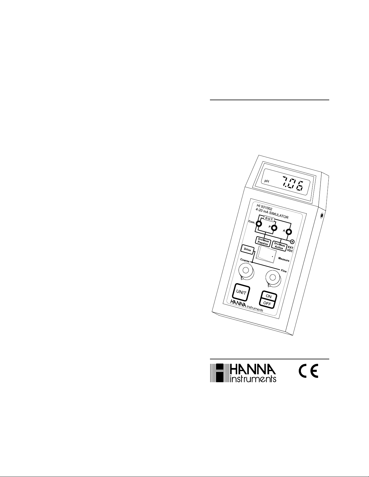
HI 931002
4-20 mA Simulator
http://www.hannainst.com
These Instruments are in
Compliance with the CE Directives
Page 2

Dear Customer,
Thank you for choosing a Hanna Instruments Product.
Please read this instruction manual carefully before using the instru-
ment.
This manual will provide you with all the necessary information for
the correct use of the instrument, as well as a precise idea of its
versatility in a wide range of applications.
These instruments are in compliance with directives EN 50081-1
and EN 50082-1.
TABLE OF CONTENTSTABLE OF CONTENTS
TABLE OF CONTENTS
TABLE OF CONTENTSTABLE OF CONTENTS
PRELIMINARY EXAMINATION....................................................... 3
GENERAL DESCRIPTION .............................................................. 3
FUNCTIONAL DESCRIPTION AND SPECIFICATIONS HI931002........ 4
OPERATIONAL GUIDE ................................................................. 5
mA - pH RELATION.................................................................... 9
BATTERY REPLACEMENT.............................................................. 9
FUSE REPLACEMENT .................................................................. 9
ACCESSORIES .......................................................................... 10
WARRANTY.............................................................................. 10
CE DECLARATION OF CONFORMITY............................................ 11
ISO 9000 Certified
Company since 1992
PRELIMINARY EXAMINATIONPRELIMINARY EXAMINATION
PRELIMINARY EXAMINATION
PRELIMINARY EXAMINATIONPRELIMINARY EXAMINATION
Remove the instrument from the packing material and examine it
carefully to make sure that no damage has occurred during shipment.
If noticeable damage is found, immediately notify your Dealer.
In addition to this manual you should find the following items:
•
HI 931002
•
12 VDC power adapter (HI710005 or HI710006);
•
1 m (3.3') connection cables;
•
9 V battery.
Note: Save all packing material until the instrument has been ob-
HI 931002 is a portable 4-20 mA simulator, ammeter and calibrator
designed specifically for monitoring and regulating a 4-20 mA current
loop from practically any process meter with or without voltage source.
Four operational modes are provided:
1) Passive Drive/Calibrator Mode. HI 931002 can be set to simulate 4-20 mA current values and the user can then adjust the process
meter accordingly.
2) Active Drive/Simulator Mode. HI 931002 simulates the correct
values as above in addition to providing power to the current loop.
Power is provided through an external adapter (included) which is
connected to the simulator. This mode is ideal for calibrating chart
recorders, pressure transducers or current indicators.
3) Passive Measurement/Tester Mode. HI 931002 practically becomes an Ammeter. It measures and displays the mA (or pH) values
transmitted by the process meter.
4) Active Measurement/Tester Mode. Same as point 3 in addition
to providing voltage to the 4-20 mA bus.
HI 931002 can practically measure incoming current, provide power
and simulate 4-20 mA output to calibrate almost any process meter.
A large LCD shows current values. You can select between drive and
measurement modes through a switch on the front panel and two
dials that allow for quick adjustment of the current.
meter;
served to function correctly. All defective items must be returned
to the Dealer in their original packing.
GENERAL DESCRIPTIONGENERAL DESCRIPTION
GENERAL DESCRIPTION
GENERAL DESCRIPTIONGENERAL DESCRIPTION
32
Page 3
FUNCTIONAL DESCRIPTION ANDFUNCTIONAL DESCRIPTION AND
FUNCTIONAL DESCRIPTION AND
FUNCTIONAL DESCRIPTION ANDFUNCTIONAL DESCRIPTION AND
SPECIFICATIONS HI 931002SPECIFICATIONS HI 931002
SPECIFICATIONS HI 931002
SPECIFICATIONS HI 931002SPECIFICATIONS HI 931002
OPERATIONAL GUIDEOPERATIONAL GUIDE
OPERATIONAL GUIDE
OPERATIONAL GUIDEOPERATIONAL GUIDE
INITIAL PREPARATION
Each meter is supplied complete with a 9V battery. Slide off the
battery compartment cover on the back of the meter (see page 9),
install the battery while paying attention to its polarity.
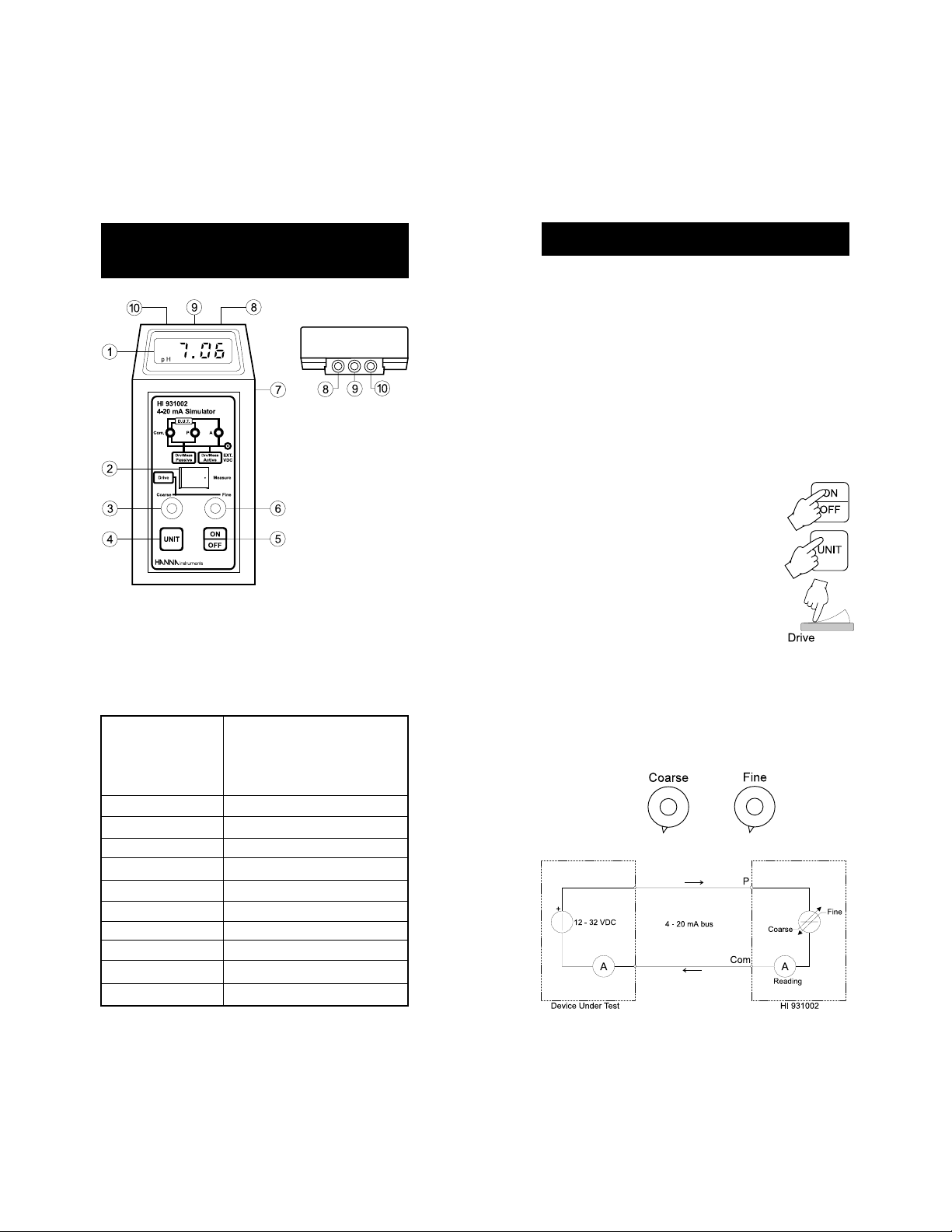
PASSIVE DRIVE (CALIBRATOR) MODE
This mode is intended to calibrate an active receiver unit.
The HI 931002 simulates 4 to 20 mA current, powered by the active
receiver from the 4-20 mA bus. The current value displayed on the
LCD, can be adjusted through two single turn potentiometers in
increments of 0.01 mA.
• Disconnect the external power adapter from HI 931002 if present.
• Turn the meter on by pressing the ON/OFF key.
• Select the measurement unit by pressing the UNIT key.
1) LCD display
2) Mode selection switch
3) coarse setting knob
4) Unit selection key
5) ON/OFF key
Range Active Drive 2.00 to 19.99 mA -1.50 to 14.00 pH
Passive Drive 2.00 to 19.99 mA -1.50 to 14.00 pH
Active Measure 0.00 to 19.99 mA -3.50 to 14.00 pH
Passive Measure 0.00 to 19.99 mA -3.50 to 14.00 pH
Resolution 0.01mA 0.01 pH
Accuracy (@20°C/68°F) ±0.01mA ±0.01 pH
EMC Typical Deviation ±1% f.s.
Input resistance 20 Ω
Fuse 5x20 mm, 200mA, 250V
Battery Type/Life 9V alkaline/1600 hours of continuous use
Ext. Power Supply 12 to 32 VDC
Environment 0 to 50°C (32 to 122°F); 95% RH
Dimensions 180 x 83 x 40 mm (7.1 x 3.3 x 1.6")
Weight 320 g (11.3 oz.)
6) fine setting knob
7) Ext. power adapter socket
8) "A" connector
9) "P" connector
10) "Com." connector.
• Switch the selection switch to the "Drive" mode.
• Wire the calibrator "Com." and "P" connectors to the Device Under
Test (D.U.T.) input contacts (see page 4, #10 and #9 respectively) using the cables provided, paying attention to the polarity
("Com." to - and "P" to + terminals).
• Turn the Fine and Coarse knobs to any desired value and make
sure that the D.U.T. reflects the current value displayed on the HI
931002 LCD.
• Calibrate the D.U.T. according to manufacturer instructions if necessary.
54
Page 4

ACTIVE DRIVE (SIMULATOR) MODE
This mode is intended to drive a chart recorder, calibrate a pressure/
current transducer or a current indicator. The HI 931002 supplies a
voltage to the 4-20 mA bus via an external connected 12-32 VDC
power supply. The calibrator regulates the current, displayed on the
LCD, as in the previous mode (Passive Drive).
PASSIVE MEASURING (TESTER) MODE
This mode is intended to test an active transmitter. The HI 931002
reads the current produced by the transmitter via the 4-20 mA bus
and displays the reading in mA or pH units.
• Disconnect the external power adapter from HI 931002 if present.
• Turn the meter on by pressing the ON/OFF key.
• Select the measurement unit by pressing the UNIT key.
• Switch the selection switch to the "Drive" mode.
• Connect the external power adapter to the power
socket on the right side of the HI 931002.
• Wire the calibrator "Com." and "A" connectors to the Device Under
Test (D.U.T.) input contacts (see page 4, #10 and #8 respectively) using the cables provided, paying attention to the polarity
("Com." to - and "A" to + terminals).
• Turn the Fine and Coarse knobs to any desired value and make
sure that the D.U.T. reflects the current value displayed on the HI
931002 LCD.
• Calibrate the D.U.T. according to manufacturer instructions if necessary.
Note: the battery powers on the display only. Calibrator operational
mode is functional even without a battery or if battery is
discharged.
• Turn the meter on by pressing the ON/OFF key.
• Select the measurement unit by pressing the UNIT key.
• Switch the selection switch to the "Measure"
mode.
• Wire the calibrator "Com." and "P" connectors to the Device Under
Test (D.U.T.) input contacts (see page 4, #10 and #9 respectively) using the cables provided, paying attention to the polarity
("Com." to - and "P" to + terminals).
• Verify that the D.U.T. displays the same reading of the HI 931002
and calibrate the D.U.T. according to manufacturer instructions if
necessary.
IMPORTANT NOTE:
Set the selection switch to MEASURE mode only if the
D.U.T. is a transmitter and can limit current below 100mA.
WRONG OPERATION WILL BREAK THE INTERNAL FUSE.
76
Page 5

ACTIVE MEASURING (TESTER) MODE
This mode is intended to test a passive transmitter. The HI 931002
supplies only the power to the 4-20 mA bus via an external connected
12-32 VDC power supply and displays the value of the current
produced by the transmitter.
• Turn the meter on by pressing the ON/OFF key.
• Select the measurement unit by pressing the UNIT
key.
• Switch the selection switch to the "Measure" mode.
• Connect the external power adapter to the power socket on the
right side of the HI931002.
• Wire the calibrator "Com." and "A" connectors to the Device Under
Test (D.U.T.) input contacts (see page 4, #10 and #8 respectively) using the cables provided, paying attention to the polarity
("Com." to - and "A" to + terminals).
• Verify that the D.U.T. displays the same reading of the HI 931002
and calibrate the D.U.T. according to manufacturer instructions if
necessary.
IMPORTANT NOTE:
Set the selection switch to MEASURE mode only if the
D.U.T. is a transmitter and can limit current below 100mA.
WRONG OPERATION WILL BREAK THE INTERNAL FUSE.
mA - pH RELATIONmA - pH RELATION
mA - pH RELATION
mA - pH RELATIONmA - pH RELATION
The HI 931002 LCD will show the current from the transmitter in mA
or in pH units according to the relation:
4 mA = 0 pH
12 mA = 7 pH mA = 1.14 x (pH reading) + 4
20 mA = 14 pH.
Press UNIT key to select the desired range. The read-
ing will toggle between the mA and pH reading.
BATTERY REPLACEMENTBATTERY REPLACEMENT
BATTERY REPLACEMENT
BATTERY REPLACEMENTBATTERY REPLACEMENT
The instruments uses a 9 volt battery that lasts for approximately
1600 hours of continuous use.
When the battery is rundown, "V" and two
decimal points blink on the LCD to warn the
user.
Battery replacement must only take place in a non
hazardous area using the battery types specified in
this instruction manual (see page 4).
To change battery, slide the bottom back cover,
replace the old battery and replace the cover.
FUSE REPLACEMENTFUSE REPLACEMENT
FUSE REPLACEMENT
FUSE REPLACEMENTFUSE REPLACEMENT
The HI 931002 is equipped with a protection fuse inside the instrument. In the event the fuse would break contact your nearest Hanna
Service.
98
Page 6

ACCESSORIESACCESSORIES
ACCESSORIES
ACCESSORIESACCESSORIES
HI 710001 Soft carrying case, dimensions 230 x 100 x 50 mm
HI 7826/1 Simulator 1 m (3.3') connection cables
HI 710031 Hard carrying case, dimensions 340 x 230 x 90 mm
HI 710005 115VAC-12VDC voltage adapter
HI 710006 230VAC-12VDC voltage adapter
HI 721310 9V battery (10 pcs)
MN931002R1Instruction manual
WARRANTYWARRANTY
WARRANTY
WARRANTYWARRANTY
All Hanna Instruments meters are warranted for two years against
defects in workmanship and materials when used for their intended
purpose and maintained according to instructions. The electrodes and
the probes are warranted for a period of six months. This warranty is
limited to repair or replacement free of charge.
Damages due to accident, misuse, tampering or lack of prescribed maintenance are not covered.
If service is required, contact the dealer from whom you purchased the
instrument. If under warranty, report the model number, date of purchase, serial number and the nature of the failure. If the repair is not
covered by the warranty, you will be notified of the charges incurred. If
the instrument is to be returned to Hanna Instruments, first obtain a
Returned Goods Authorization number from the Customer Service department and then send it with shipping costs prepaid. When shipping any
instrument, make sure it is properly packaged for complete protection.
To validate your warranty, fill out and return the enclosed warranty card
within 14 days from the date of purchase.
All rights are reserved. Reproduction in whole or in part is prohibited
without the written consent of the copyright owner,
Hanna Instruments Inc., 584 Park East Drive, Woonsocket, Rhode Island,
02895 , USA.
Hanna Instruments reserves the right to modify the design, construction and appearance of its products without advance notice.
CE DECLARATION OF CONFORMITYCE DECLARATION OF CONFORMITY
CE DECLARATION OF CONFORMITY
CE DECLARATION OF CONFORMITYCE DECLARATION OF CONFORMITY
Recommendations for Users
Before using these products, make sure that they are entirely suitable for the environment
in which they are used.
Operation of these instruments in residential area could cause unacceptable interferences
to radio and TV equipments, requiring the operator to take all necessary steps to correct
interferences.
Any variation introduced by the user to the supplied equipment may degrade the
instruments' EMC performance.
To avoid damages or burns, do not perform any measurement in microwave ovens.
1110
Page 7

PRINTED IN
PORTUGAL
MN931002R1
04/98
http://www.hannainst.com
 Loading...