

Page 1
HI83300
Multiparameter Photometer
for Water & Wastewater
INSTRUCTION MANUAL
Page 2

Dear
Customer,
Thank you for choosing a Hanna Instruments product.
Please read this instruction manual carefully before using this instrument.
This manual will provide you with the necessary information for correct use of this
instrument, as well as a precise idea of its versatility.
If you need additional technical information, do not hesitate to e‑mail us at
All rights are reserved. Reproduction in whole or in part is prohibited without the written consent of the
copyright owner, Hanna Instruments Inc., Woonsocket, Rhode Island, 02895, USA.
Page 3

TABLE OF CONTENTS
1. PRELIMINARY EXAMINATION ............................................................................................... 7
2. SAFETY MEASURES ............................................................................................................. 7
3. SPECIFICATIONS ................................................................................................................. 8
4. ABBREVIATIONS ................................................................................................................ 9
5. DESCRIPTION ................................................................................................................... 10
5.1. GENERAL DESCRIPTION & INTENDED USE ................................................................ 10
5.2. PRECISION & ACCURACY .......................................................................................... 10
5.3. FUNCTIONAL DESCRIPTION ...................................................................................... 11
5.4. PRINCIPLE OF OPERATION ....................................................................................... 12
5.5. OPTICAL SYSTEM ..................................................................................................... 13
6. GENERAL OPERATIONS ...................................................................................................... 14
6.1. POWER CONNECTION & BATTERY MANAGEMENT ....................................................... 14
6.2. MODE SELECTION ................................................................................................... 14
6.3. GENERAL SETUP ..................................................................................................... 15
6.4. CONTEXTUAL HELP .................................................................................................. 18
7. LOGGING DATA & DATA MANAGEMENT................................................................................ 19
7.1. LOGGING DATA ....................................................................................................... 19
7.2. ADDING SAMPLE & USER NAMES TO LOG DATA ......................................................... 19
7.3. DATA MANAGEMENT ................................................................................................ 20
8. PHOTOMETER MODE ......................................................................................................... 21
8.1. METHOD SELECTION ............................................................................................... 21
8.2. COLLECTING & MEASURING SAMPLES AND REAGENTS ................................................ 21
8.3. CUVETTE PREPARATION ........................................................................................... 22
8.4. TIMERS & MEASUREMENT FUNCTIONS ..................................................................... 24
8.5. CHEMICAL FORMULA & UNIT CONVERSION ............................................................... 24
8.6. METER VALIDATION & CAL CHECK ............................................................................. 25
8.7. ABSORBANCE MEASUREMENTS ................................................................................ 26
9. PROBE MODE ................................................................................................................... 27
9.1. pH MEASUREMENT ................................................................................................. 27
9.2. pH CALIBRATION ..................................................................................................... 28
TABLE OF CONTENTS
3
Page 4

9.3. pH MESSAGES & WARNINGS ................................................................................... 29
9.4. pH GLP .................................................................................................................. 30
9.5. pH ELECTRODE CONDITIONING & MAINTENANCE ....................................................... 31
10. METHOD PROCEDURES ................................................................................................... 33
10.1. ALKALINITY ........................................................................................................... 33
10.2. ALKALINITY, MARINE ............................................................................................. 35
10.3. ALUMINUM .......................................................................................................... 37
TABLE OF CONTENTS
10.4. AMMONIA LOW RANGE .......................................................................................... 41
10.5. AMMONIA MEDIUM RANGE ................................................................................... 44
10.6. AMMONIA HIGH RANGE ........................................................................................ 47
10.7. BROMINE ............................................................................................................. 50
10.8. CALCIUM .............................................................................................................. 52
10.9. CALCIUM, MARINE ................................................................................................ 55
10.10. CHLORIDE .......................................................................................................... 57
10.11. CHLORINE DIOXIDE ............................................................................................. 60
10.12. CHLORINE DIOXIDE, RAPID METHOD .................................................................... 64
10.13. CHLORINE, FREE ................................................................................................. 68
10.14. CHLORINE, FREE ULTRA LOW RANGE .................................................................... 71
10.15. CHLORINE, TOTAL ............................................................................................... 73
10.16. CHLORINE, TOTAL ULTRA LOW RANGE ................................................................... 77
10.17. CHLORINE, TOTAL ULTRA HIGH RANGE .................................................................. 79
10.18. CHROMIUM(VI) LOW RANGE ................................................................................ 81
10.19. CHROMIUM(VI) HIGH RANGE ............................................................................... 83
10.20. COLOR OF WATER ............................................................................................... 85
10.21. COPPER LOW RANGE ........................................................................................... 87
10.22. COPPER HIGH RANGE .......................................................................................... 89
10.23. CYANURIC ACID................................................................................................... 91
10.24. FLUORIDE LOW RANGE ........................................................................................ 93
10.25. FLUORIDE HIGH RANGE ....................................................................................... 95
10.26. HARDNESS, CALCIUM .......................................................................................... 98
10.27. HARDNESS, MAGNESIUM .................................................................................. 101
10.28. HARDNESS, TOTAL LOW RANGE .......................................................................... 104
4
Page 5

10.29. HARDNESS, TOTAL MEDIUM RANGE ................................................................... 107
10.30. HARDNESS, TOTAL HIGH RANGE ......................................................................... 110
10.31. HYDRAZINE ...................................................................................................... 113
10.32. IODINE ............................................................................................................ 115
10.33. IRON LOW RANGE ............................................................................................. 117
10.34. IRON HIGH RANGE ............................................................................................ 120
10.35. IRON(II) ........................................................................................................... 122
10.36. IRON(II)/(III) ................................................................................................... 125
10.37. MAGNESIUM .................................................................................................... 129
10.38. MANGANESE LOW RANGE .................................................................................. 131
10.39. MANGANESE HIGH RANGE ................................................................................. 134
10.40. MOLYBDENUM ................................................................................................. 137
10.41. NICKEL LOW RANGE .......................................................................................... 140
10.42. NICKEL HIGH RANGE ......................................................................................... 143
10.43. NITRATE ........................................................................................................... 145
10.44. NITRITE, MARINE ULTRA LOW RANGE ................................................................. 148
10.45. NITRITE LOW RANGE ......................................................................................... 150
10.46. NITRITE HIGH RANGE ........................................................................................ 152
10.47. OXYGEN, DISSOLVED ........................................................................................ 154
10.48. OXYGEN SCAVENGERS (CARBOHYDRAZIDE) ......................................................... 157
10.49. OXYGEN SCAVENGERS (DIETHYLHYDROXYLAMINE) (DEHA) ................................... 160
10.50. OXYGEN SCAVENGERS (HYDROQUINONE) ........................................................... 163
10.51. OXYGEN SCAVENGERS (ISO-ASCORBIC ACID) ....................................................... 166
10.52. OZONE ............................................................................................................. 169
10.53. pH ................................................................................................................... 173
10.54. PHOSPHATE, MARINE ULTRA LOW RANGE ........................................................... 175
10.55. PHOSPHATE LOW RANGE ................................................................................... 177
10.56. PHOSPHATE HIGH RANGE .................................................................................. 179
10.57. POTASSIUM ..................................................................................................... 182
10.58. SILICA LOW RANGE ........................................................................................... 185
10.59. SILICA HIGH RANGE .......................................................................................... 188
10.60. SILVER ............................................................................................................. 191
TABLE OF CONTENTS
5
Page 6

10.61. SULFATE .......................................................................................................... 195
10.62. SURFACTANTS, ANIONIC .................................................................................... 197
10.63. ZINC ................................................................................................................ 201
11. WARNINGS & ERRORS .................................................................................................. 203
12. STANDARD METHODS ................................................................................................... 206
13. ACCESSORIES ............................................................................................................... 209
13.1. REAGENT SETS.................................................................................................... 209
TABLE OF CONTENTS
13.2. pH ELECTRODES ................................................................................................. 213
13.3. pH SOLUTIONS ................................................................................................... 214
13.4. OTHER ACCESSORIES .......................................................................................... 216
CERTIFICATION .................................................................................................................... 218
RECOMMENDATIONS FOR USERS .......................................................................................... 218
WARRANTY ......................................................................................................................... 218
6
Page 7

1. PRELIMINARY EXAMINATION
Remove the instrument and accessories from the packaging and examine it carefully. For further
assistance, please contact your local Hanna Instruments Office or email us at [email protected].
Each HI83300 is delivered in a rugged carrying case and is supplied with:
• Sample cuvette (4 pcs.)
• Sample cuvette cap (4 pcs.)
• Cloth for wiping cuvettes
• Scissors
• USB cable
• 5 Vdc power adapter
• 60 mL glass bottle
• Instrument quality certificate
• Instruction manual
Note: Save all packing material until you are sure that the instrument works correctly. Any
damaged or defective item must be returned in its original packing material with the supplied
accessories.
PRELIMINARY EXAMINATION
2. SAFETY MEASURES
• The chemicals contained in the reagent kits may be hazardous if improperly handled.
• Read the Safety Data Sheets (SDS) before performing tests.
• Safety equipment: Wear suitable eye protection and clothing when required and follow
instructions carefully.
• Reagent spills: If a reagent spill occurs, wipe up immediately and rinse with plenty of
water. If reagent contacts skin, rinse the affected area thoroughly with water. Avoid
breathing released vapors.
• Waste disposal: For proper disposal of reagent kits and reacted samples, contact a
licensed waste disposal provider.
SAFETY MEASURES
7
Page 8

3. SPECIFICATIONS
SPECIFICATIONS
Measurement Channels
Range 0.000 to 4.000 Abs
Resolution 0.001 Abs
Accuracy ±0.003 Abs @ 1.000 Abs
Light source Light Emitting Diode
Photometer
Probe
Temperature
Additional
Specifications
Bandpass filter bandwidth 8 nm
Bandpass filter wavelength accuracy ±1.0 nm
Light detector Silicon photocell
Cuvette types Round, 24.6 mm diameter
Number of methods 68
Range -2.00 to 16.00 pH (± 1000.0 mV)*
Resolution 0.01 pH (0.1 mV)
Accuracy ±0.01 pH (±0.2 mV) @ 25 °C / 77 °F
Temperature compensation ATC, -5.0 to 100.0 °C (23.0 to 212.0 °F)*
Calibration
Electrode Intelligent pH / temperature electrode
Range -20.0 to 120.0 °C (-4.0 to 248.0 °F)
Resolution 0.1 °C (0.1 °F)
Accuracy ±0.5 °C @ 25 °C (±0.9 °F @ 77 °F)
Logging 1000 readings (mixed photometer and electrode)
Display 128 x 64 pixel B/W LCD with backlight
USB-A (Host) functions Mass-storage host
USB-B (Device) functions Power input, mass-storage device
Battery life
Power supply
Environment
Dimensions 206 x 177 x 97 mm (8.1 x 7.0 x 3.8")
Weight 1.0 kg (2.2 lbs.)
*Limits will be reduced to actual probe / sensor limits.
5 x optical channels
1 x digital electrode channel (pH measurement)
two-point, from five available buffers
(4.01, 6.86, 7.01, 9.18, 10.01 pH)
> 500 photometer measurements or 50 hours
of continuous pH measurement
5 Vdc USB 2.0 power adapter / type micro-B
connector
3.7 Vdc Li-polymer rechargeable battery,
non-serviceable
0 to 50 °C (32 to 122 °F)
0 to 95% RH, non-serviceable
8
Page 9

4. ABBREVIATIONS
Abs Absorbance
GLP Good Laboratory Practice
NIST National Institute of Standards and Technology
EPA US Environmental Protection Agency
g/L grams per liter (parts per thousand, ppt)
µg/L micrograms per liter (parts per billion, ppb)
mg/L milligrams per liter (parts per million, ppm)
HR High Range
LR Low Range
MR Medium Range
UHR Ultra High Range
ULR Ultra Low Range
ABBREVIATIONS
9
Page 10

5. DESCRIPTION
5.1. GENERAL DESCRIPTION & INTENDED USE
HI83300 multiparameter photometer is a compact and versatile meter with two measurement modes,
Photometer and Probe. Photometer mode includes a CAL Check™ feature and 68 different methods
DESCRIPTION
that cover a wide variety of applications, making it ideal for both benchtop and portable operations.
With the CAL Check™ feature users are able to validate the performance of the instrument and
apply a user calibration (if necessary). Hanna Instruments CAL Check™ cuvettes are made with NIST
traceable standards. Probe mode uses a digital pH probe with a one or two-point calibration.
• Digital electrode input for pH measurements
• Certified CAL Check cuvettes to confirm meter functionality
• Dual purpose micro-USB flash drive
• Lithium polymer rechargeable battery
• Auto-off
• Absorbance mode
• User and sample name entry
• GLP features
5.2. PRECISION & ACCURACY
Precision is how closely repeated measurements are to one another. Precision is usually expressed as
standard deviation. Accuracy is defined as the closeness of a test result to the true value. Although
good precision suggests good accuracy, precise results can be inaccurate. The figure explains these
definitions. For each method, the accuracy is expressed in the related measurement section.
10
Page 11
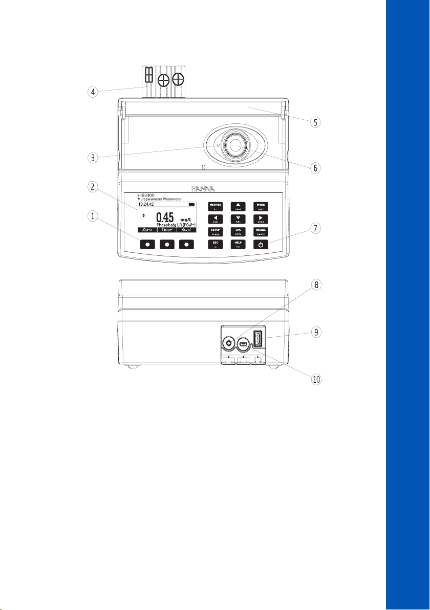
5.3. FUNCTIONAL DESCRIPTION
DESCRIPTION
1. Splash-proof keypad
2. Liquid Crystal Display (LCD)
3. Indexing mark
4. Protective port covers
5. Light-blocking cover panel
6. Cuvette holder
7. ON/OFF power button
8. 3.5 mm TRRS (jack) input for digital electrodes
9. Standard USB host connector for data transfer to a USB flash drive
10. Micro-USB device connector for power or PC interface
11
Page 12

Keypad Description
The keypad contains 12 direct keys and 3 functional keys with the following functions:
Press the functional key to perform the function displayed above it on the LCD.
DESCRIPTION
Press to access the list of photometer methods.
Press to move up in a menu or a help screen, to increment a set value or to access second
level functions.
Press to toggle between photometer and probe (pH electrode) mode.
Press to move left in a menu or to decrement a set value.
Press to move down in a menu or a help screen, to decrement a set value or to access second
level functions.
Press to move right in a menu or to increment a set value.
Press to access the setup screen.
Press to log the current reading.
Press to review saved logs.
Press to exit the current screen.
Press to display the help screen.
ON/OFF power button
12
5.4. PRINCIPLE OF OPERATION
Absorption of light is a typical phenomenon of interaction between electromagnetic radiation and
matter. When a light beam crosses a substance, some of the radiation may be absorbed by atoms,
molecules or crystal lattices. Photometric chemical analysis is based on specific chemical reactions
between a sample and reagent to produce a light-absorbing compound.
If pure absorption occurs, the fraction of light absorbed depends both on the optical path length
through the matter and on the physical-chemical characteristics of the substance according to the
Lambert-Beer Law. If all other factors are constant, the concentration "c" can be calculated from the
absorbance of the substance.
Page 13
Lambert Beer Law:
-log I/Io = el c d
A = el c d
= intensity of incident light beam
I
o
I = intensity of light beam after absorption
e
= molar extinction coefficient at wavelength l
l
c = molar concentration of the substance
d = optical path through the substance
5.5. OPTICAL SYSTEM
DESCRIPTION
or
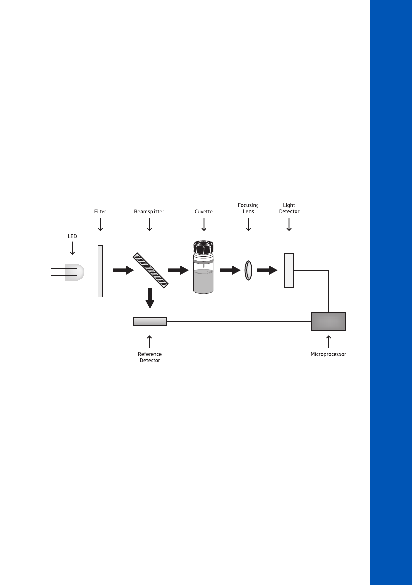
Instrument Block Diagram
The internal reference system (reference detector) of the HI83300 photometer compensates for any
drifts due to power fluctuations or ambient temperature changes, providing a stable source of light for
your blank (zero) measurement and sample measurement.
LED light sources offer superior performance compared to tungsten lamps. LEDs have a much higher
luminous efficiency, providing more light while using less power. They also produce little heat, which
could otherwise affect electronic stability. LEDs are available in a wide array of wavelengths, whereas
tungsten lamps have poor blue / violet light output.
Improved optical filters ensure greater wavelength accuracy and allow a brighter, stronger signal to be
received. The end result is higher measurement stability and less wavelength error.
A focusing lens collects all of the light that exits the cuvette, eliminating errors from cuvette
imperfections and scratches, eliminating the need to index the cuvette.
13
Page 14
GENERAL OPERATIONS
6. GENERAL OPERATIONS
6.1. POWER CONNECTION & BATTERY MANAGEMENT
The meter can be powered from an AC / DC adapter (included) or from the built-in rechargeable
battery.
The meter will perform an auto-diagnostic test when it is first powered on. During this test, the Hanna
Instruments logo will appear on the LCD. After 5 seconds, if the test was successful, the last method
used will appear on the display.
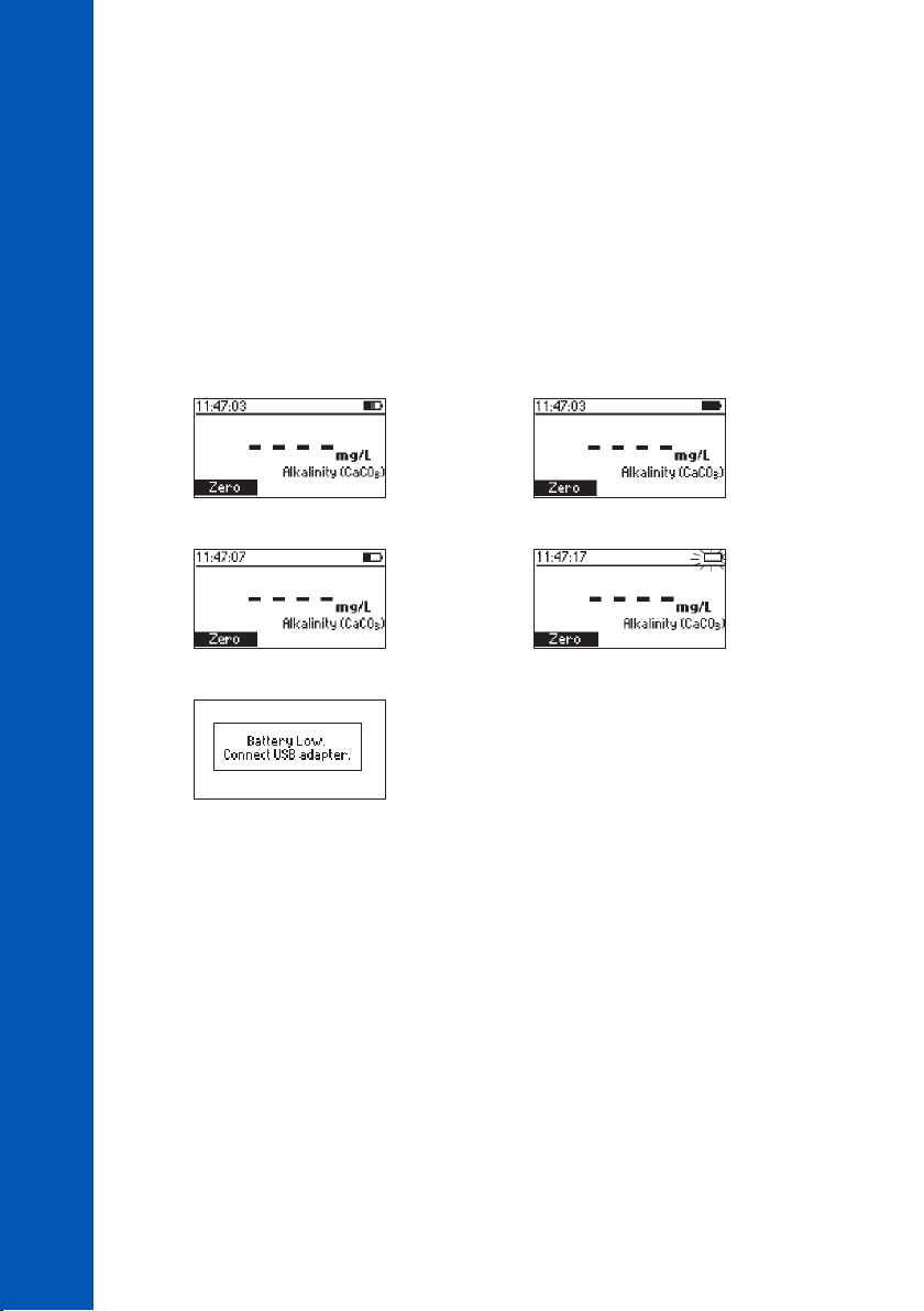
The battery icon on the LCD will indicate the battery status:
• battery is charging from external adapter • battery fully charged (meter connected to AC / DC adapter)
• battery capacity (no external adapter) • battery near 0% (no external adapter)
• battery exhausted (no external adapter)
14
To conserve battery, the meter will turn off automatically after 15 minutes of inactivity (30 minutes
after a Zero measurement). If a photometer measurement is on the screen, an auto-log is created
before shutdown.
6.2. MODE SELECTION
The HI83300 has two operational modes: Photometer and Probe.
Photometer mode enables on-demand measurement of a cuvette using the integrated optical system.
Probe mode enables continuous measurement using a Hanna digital electrode connected to the
3.5 mm port.
To switch between Photometer mode and Probe mode, use the MODE key.
Note: The active mode cannot be switched while in Setup, Recall or Method menus.
Page 15
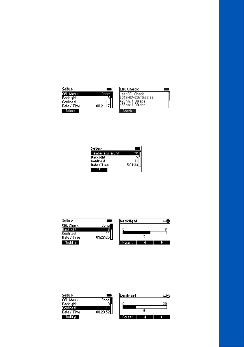
6.3. GENERAL SETUP
Press the SETUP key to enter in Setup menu, highlight desired option using the keys and
press Select.
CAL Check (Photometer Mode Only)
Press Select to enter the CAL Check screen. The date, time and values for the last CAL Check are
displayed on the screen. To start a new CAL Check press Check and follow the prompts on the screen.
See METER VALIDATION & CAL CHECK for additional information.
Temperature Unit (Probe Mode Only)
Option: °C or °F
Press the functional key to select the desired temperature unit.
Backlight
Values: 0 to 8
Press Modify to access the backlight intensity. Use the functional keys or the keys to increase or
decrease the value. Press Accept to confirm or press the ESC key to return to the Setup menu without
saving the new value.
GENERAL OPERATIONS
Contrast
Values: 0 to 20
Press Modify to change the display’s contrast. Use the functional keys or the keys to increase
or decrease the value. Press Accept to confirm the value or the ESC key to return to the Setup menu
without saving the new value.
15
Page 16
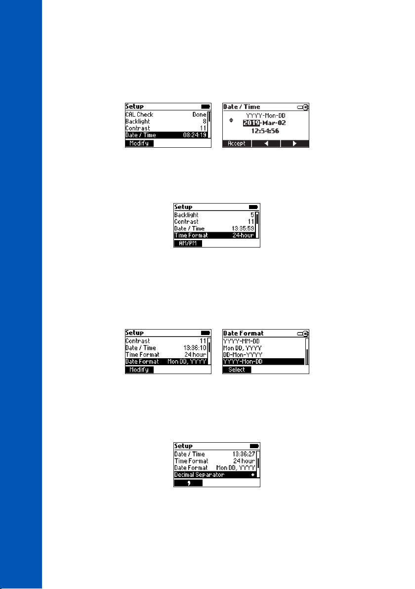
Date & Time
Press Modify to change the date and time. Press the functional keys or the keys to highlight the
value to be modified (year, month, day, hour, minute or second). Use the keys to change the
value. Press Accept to confirm or ESC key to return to the Setup without saving the new date or time.
GENERAL OPERATIONS
Time Format
Option: AM/PM or 24-hour
Press the functional key to select the desired time format.
Date Format
Option: DD/MM/YYYY, MM/DD/YYYY, YYYY/MM/DD, YYYY-MM-DD, Mon DD, YYYY,
DD-Mon-YYYY, YYYY-Mon-DD
Press Modify to change the date format. Use the keys to select the desired format. Press Select
to confirm or the ESC key to return to the Setup menu without saving the new format.
Decimal Separator
Option: Comma ( , ) or Period ( . )
Press the functional key to select the desired decimal separator. The decimal separator is used on the
measurement screen and CSV (Comma-Separated Values) files.
16
Page 17
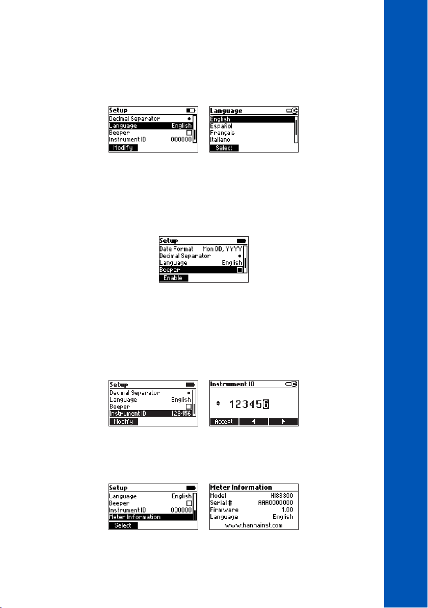
Language
Option: Português, Deutsch, English, Español, Français, Italiano, Dutch
Press Modify to change the language. Use the keys to select the desired language. Press Select
to change the language.
Beeper
Option: Enable or Disable
When enabled, a short beep is heard every time a key is pressed. A long beep alert sounds when
the pressed key is not active or an error is detected. Press the functional key to enable or disable the
beeper.
Instrument ID
Option: 0 to 999999
This option is used to set the instrument’s ID (identification number). Press Modify to access the
instrument ID screen. Use the functional keys or the keys to highlight the digit to be modified.
Press the keys in order to set the desired value. Press Accept to confirm the value or press the
ESC key to return to the Setup menu without saving the new value.
GENERAL OPERATIONS
Meter Information
Press Select to view the model, serial number, firmware version and selected language. Press the ESC
key to return to the Setup menu.
17
Page 18
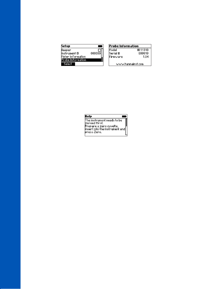
Probe Information (pH Mode Only)
Press Select to view model number, serial number and firmware version for the connected probe. Press
the ESC key to return to the Setup menu.
GENERAL OPERATIONS
6.4. CONTEXTUAL HELP
HI83300 offers an interactive contextual help mode that assists the user at any time.
To access the help screen press the HELP key. The instrument will display additional information
related to the current screen. To read all the available information, scroll the text using the keys.
Press the ESC key to return to the previous screen.
18
Page 19
7. LOGGING DATA & DATA MANAGEMENT
The instrument features a data log function to help you keep track of all your analysis. The data log
can hold 1000 individual measurements. Storing, viewing and deleting the data is possible using the
LOG and RECALL keys.
7.1. LOGGING DATA
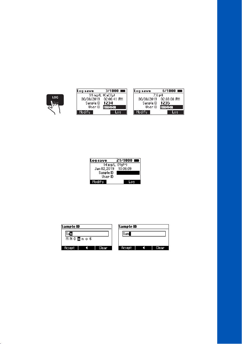
Press the LOG key and the last valid measurement will be stored with a date and time stamp. Only
valid measurements can be stored.
7.2. ADDING SAMPLE & USER NAMES TO LOG DATA
A sample ID and user ID can be added to the saved log. Use the keys to highlight the Sample
ID or User ID then press Modify. Sample ID and user ID are entered using the alphanumeric multitapping keypad.
LOGGING DATA & DATA MANAGEMENT
Enter one character at a time by pressing the key with the assigned character repeatedly until the
desired character is highlighted. For reference, a list of the characters available for the current key will
be shown under the text box.
The character will be entered after a two-second delay or after another key is pressed.
Press Accept to update the sample or user ID.
Press functional key to delete the last character.
Press Clear to delete all of the characters.
Press the ESC key to discard all changes and return to the previous screen.
19
Page 20
7.3. DATA MANAGEMENT
Viewing & Deleting
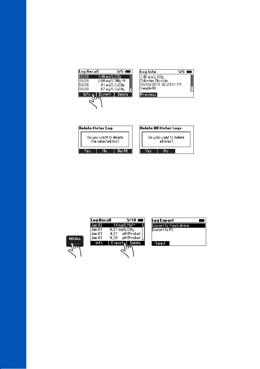
Data can be viewed, deleted and exported to a USB drive or a PC by pressing the RECALL key. Use
the keys to scroll through the saved logs. Press Info to view additional information about the
selected log.
Use Delete to erase logged data. After pressing Delete the prompt on the display will confirm the action.
LOGGING DATA & DATA MANAGEMENT
Press No or the ESC key to return to the previous screen.
Press Yes to delete the selected log.
Press Del All to erase all the logged data. If Del All is pressed the prompt on the display will confirm
the action. Press Yes to delete all logged data, No or the ESC key to return to the log recall.
Data Export
Log data can be exported to a USB flash drive or to a PC. To access data export functions, press the
RECALL key then Export.
20
Use the keys to select the desired export location.
For export to flash drive, insert the USB flash drive into the dedicated port at the back of the meter
labeled HOST USB, then follow the on-screen prompts.
For export to PC, connect the meter to a PC using the supplied micro-USB cable. Insert the cable into
the port at the back of the meter labeled PC PWR. Follow the on-screen prompts. When the meter
says PC connected, the meter will appear as a removable disk. Use a file manager (such as Windows
Explorer or Mac Finder) to move the file from the meter to the PC.
Log data is exported as a single file (HI83300.csv) containing all logged photometer and probe data.
The CSV file may be opened with a text editor or spreadsheet application.
Page 21
8. PHOTOMETER MODE
8.1. METHOD SELECTION
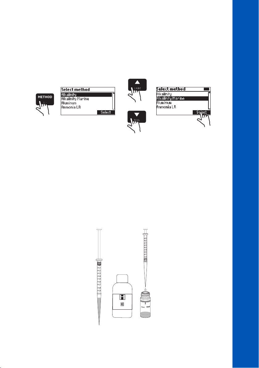
In order to select the desired method press the METHOD key and a screen with the available methods
will appear.
Press the keys to highlight the desired method. Press Select.
After the desired method is selected, follow the procedure described in the related section.
Before performing a method, read all the instructions carefully.
8.2. COLLECTING & MEASURING SAMPLES AND REAGENTS
Proper Use of Syringe
1. Push the plunger completely into the syringe and insert the tip into the solution.
2. Pull the plunger up until the lower edge of the seal is exactly on the mark for the desired volume.
3. Take out the syringe and clean the outside of the syringe tip, be sure that no drops are hanging
on the tip of the syringe. Then, keeping the syringe in a vertical position, push the plunger down
into the syringe, the desired volume has been delivered.
PHOTOMETER MODE
21
Page 22
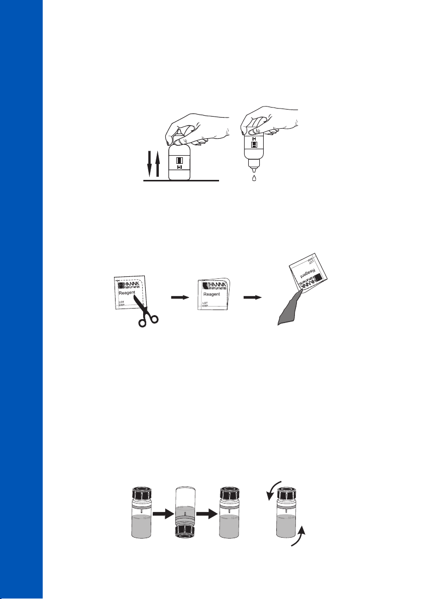
Proper Use of Dropper Bottle
1. Tap the dropper on the table several times.
2. Remove the cap and wipe the outside of the tip with a cloth.
3. Keep the dropper bottle in a vertical position while dosing the reagent.
PHOTOMETER MODE
Proper Use of Powder Packet
1. Use scissors to open the powder packet.
2. Push the edges of the packet to form a spout.
3. Pour out the content of the packet.
22
8.3. CUVETTE PREPARATION
Proper mixing is very important for reproducibility of the measurements. The proper mixing technique
for each method is listed in the method procedure.
(a) Invert the cuvette a couple of times or for a specified time: hold the cuvette in the vertical
position. Turn the cuvette upside-down and wait for all of the solution to flow to the cap end,
then return the cuvette to the upright vertical position and wait for all of the solution to flow to
the cuvette bottom. This is one inversion. The correct speed for this mixing technique is 10 to 15
complete inversions in 30 seconds. This mixing technique is indicated with “invert to mix” and
one of the following icons:
Page 23
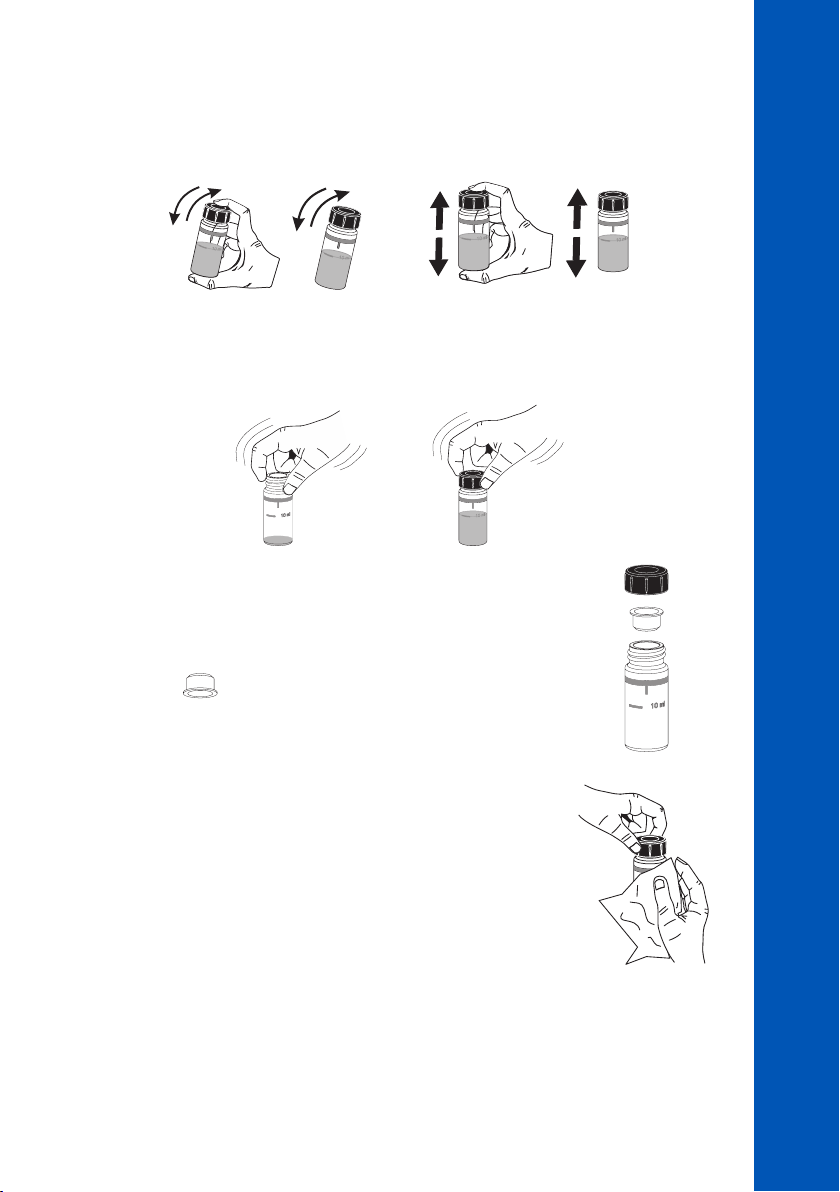
(b) Shaking the cuvette, moving the cuvette up and down. The movement may be gentle or vigorous.
This mixing technique is indicated with “shake gently” or “shake vigorously”, and one of the
following icons:
shake gently shake vigorously
(c) Swirl the cuvette gently to mix the solution. This mixing technique is indicated with one of the
following icons:
In order to avoid reagent leaking and to obtain more accurate measurements,
close the cuvette first with the supplied High-Density Polyethylene (HDPE)
plastic stopper and then the black cap.
PHOTOMETER MODE
Whenever the cuvette is placed into the measurement holder, it must be
dry outside and free of fingerprints, oil and dirt. Wipe it thoroughly with
HI731318 microfiber cleaning cloth or a lint-free wipe prior to insertion.
Shaking the cuvette can generate bubbles in the sample, causing higher
readings. To obtain accurate measurements, remove such bubbles by
swirling or by gently tapping the cuvette.
Do not let the reacted sample stand too long after reagent is added. For best accuracy, respect the
timings described in each specific method.
It is possible to take multiple readings in a row, but it is recommended to take a new zero reading for
each sample and to use the same cuvette for zeroing and measurement when possible.
23
Page 24

Discard the sample immediately after the reading is taken, or the glass might become permanently
stained.
All the reaction times reported in this manual are at 25 °C (77 °F). In general, the reaction time
should be increased for temperatures lower than 20 °C (68 °F) and decreased for temperatures higher
than 25 °C (77 °F).
Interferences
In the method measurement section the most common interferences that may be present in a typical
PHOTOMETER MODE
water sample have been reported. It is possible that a particular application could introduce other
compounds that will also interfere.
8.4. TIMERS & MEASUREMENT FUNCTIONS
Each method requires a different preparation procedure, reaction times and sample preparations. If a
timer or timers are necessary for proper sample preparation, the Timer will be available.
To use a reaction timer, press Timer. The default timer will start immediately. To stop and reset the
timer, press Stop.
If the selected method requires more than one timer, the meter will automatically select each timer
in the appropriate order. To bypass the default order, you may press the desired key to activate a
different timer (only while the current timer is stopped). Press Continue to start the active timer.
For some methods, the timer is only necessary after a Zero measurement has been performed. In this
case, the timer key will only be available after the Zero measurement has been performed.
If the method requires a Zero or Read measurement after a timer has expired, the meter will
automatically perform the appropriate action. Follow the instructions in the method procedure.
To perform a Zero or Read measurement, insert the prepared cuvette, then press Zero or Read. A Zero
measurement must be conducted before a Read measurement.
24
8.5. CHEMICAL FORMULA & UNIT CONVERSION
Chemical formula and unit conversion factors are pre-programmed into the instrument and are
method specific. In order to view the displayed result in the desired chemical formula press the
keys to access the second level function and then press Chem Frm to toggle between the available
chemical formulas for the selected method.
Page 25
8.6. METER VALIDATION & CAL CHECK
Warning: Do not validate the meter with standard solutions other than the Hanna Instruments
®
CAL Check Standards. For accurate validation results, please perform tests at room temperature,
18 to 25 °C (64.4 to 77.0 °F).
Validation of the HI83300 involves absorbance measurements of certified Hanna Instruments
®
CAL Check Standards (see ACCESSORIES section). The CAL Check screen guides the user through the
measurement of each CAL Check Standard and applies the factory calibration corrections to each
measurement. The HI83300 stores the results of the most recent CAL Check measurements which may
be viewed on the CAL Check screen. Compare these results with the values printed on the Certificate
provided with each Hanna Instruments® CAL Check Standards kit.
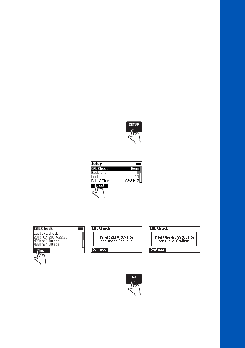
To perform a validation:
1. Press the SETUP key.
2. Highlight CAL Check, then press Select.
PHOTOMETER MODE
3. Follow the prompts on the screen. The meter will prompt to measure each cuvette provided in the
Hanna Instruments® CAL Check Standards kit. To exit the process at any time, press ESC key.
4. Press the ESC key to return in Setup menu.
25
Page 26

8.7. ABSORBANCE MEASUREMENTS
Raw absorbance measurements may be performed on the HI83300 for personal or diagnostic
purposes. For example, you may monitor the stability of a reagent blank by occasionally measuring
its absorbance versus deionized water.
To measure the raw absorbance of a prepared sample:
1. Press the METHOD key.
PHOTOMETER MODE
2. Highlight the appropriate absorbance method (according to the wavelength to be used), then
press Select. Absorbance methods are located at the bottom of the method list.
3. Prepare the sample cuvette according to the method.
4. Insert a cuvette filled with deionized water, then press Zero.
5. Insert the prepared sample cuvette, then press Read.
Warning: Never use absorbance methods for validation using Hanna Instruments
cuvettes. The factory calibration corrections for CAL Check cuvettes are applied while in CAL Check
mode only!
®
CAL Check
26
Page 27

9. PROBE MODE
9.1. pH MEASUREMENT
The HI83300 can be used to perform direct pH measurements by connecting a Hanna Instruments
digital pH electrode with a 3.5 mm TRRS connector. Connect the electrode to the 3.5 mm port marked
with EXT PROBE located at the rear of the meter. If the meter is in Photometer mode, set the meter to
Probe mode by pressing the MODE key.
Press Calibrate to open the calibration window.
Press GLP to review the calibration information.
Press Range to switch between pH and mV.
For high accuracy it is recommended to calibrate your electrode often. pH electrodes should be
recalibrated at least once per week, but daily calibration is recommended. Always recalibrate after
cleaning an electrode, see pH CALIBRATION section for more information.
To take pH measurements:
• Remove the protective cap and rinse the electrode with water.
• Collect some sample in a clean, dry beaker.
• Preferably, rinse the electrode with a small amount of sample.
• Submerse the electrode tip approximately 3 cm (1¼”) into the sample to be tested and stir the
sample gently. Make sure the electrode junction is completely submersed.
• Allow time for the electrode to stabilize in the sample. When the symbol disappears, your
reading is stable.
If measurements are taken successively in different samples, it is recommended to rinse the electrodes
thoroughly with deionized or distilled water and then with some of the next sample to prevent
cross-contamination.
pH measurements are affected by temperature. Hanna Instruments® digital pH electrodes include
a built-in temperature sensor and automatically calculate corrected pH values. The measured
temperature is displayed on the screen with the pH measurements.
®
PROBE MODE
27
Page 28

9.2. pH CALIBRATION
From the probe measurement screen, press Calibrate to begin the calibration process. During pH
calibration, the display will show the current pH reading, temperature reading, selected buffer type
and the buffer number (“Buffer: 1” for the first buffer, “Buffer: 2” for the second buffer).
PROBE MODE
Press Clear to clear the current calibration.
Press Confirm to accept the current calibration point (only available if the reading is stable and within
the limits for the selected buffer).
Press the keys to cycle through the list of available buffers: pH 4.01, 6.86, 7.01, 9.18, 10.01.
Press the ESC key to exit calibration and return to pH measurement mode.
Preparation
Pour small quantities of the buffer solutions into clean beakers. If possible, use plastic beakers to
minimize any EMC interferences. For accurate calibrations and to minimize cross-contamination, use
two beakers for each buffer solution: one for rinsing the electrode and one for calibration. If you are
measuring in the acidic range, use pH 7.01 or 6.86 as the first buffer and pH 4.01 as the second
buffer. If you are measuring in the alkaline range, use pH 7.01 or 6.86 as the first buffer and pH
10.01 or 9.18 as the second buffer.
28
Procedure
Calibration can be performed using one or two calibration buffers. For more accurate measurements,
a two-point calibration is recommended.
Submerse the pH electrode approximately 3 cm (1¼”) into a buffer solution and stir gently.
When the reading is stable and close to the selected buffer, press Confirm to accept and store the
calibration point. The meter will prompt for the second buffer (Buffer: 2). To use only a one-point
calibration, press the ESC key to exit calibration mode. The meter will store the calibration information
to the probe and return to measurement mode. To continue calibrating with a second buffer, rinse and
submerse the pH electrode approximately 3 cm (1¼”) into the second buffer solution and stir gently.
If necessary, use the keys to select a different buffer value.
When the reading is stable and close to the selected buffer, press Confirm to accept and store the
second calibration point.
The meter will store the two-point calibration information to the probe and return to Measurement
mode. The list of calibrated buffers will appear at the bottom of the screen.
Page 29
9.3. pH MESSAGES & WARNINGS
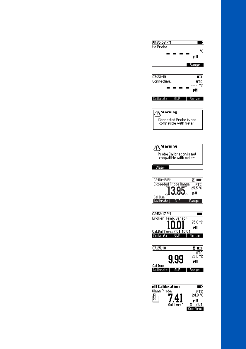
No Probe
No probe is connected or the probe is broken.
Connecting
The meter has detected a probe and is reading the probe
configuration and calibration information.
Incompatible Probe
The connected probe is not compatible with this device.
Incompatible Calibration
The probe’s current calibration is not compatible with this meter.
The calibration must be cleared to use this probe.
Exceeded Probe Range
The pH and / or temperature measurement exceed the specifications
of the probe. The measurement value(s) will be blinking.
PROBE MODE
Broken Temperature Sensor
The temperature sensor inside the probe is broken. Temperature
compensation will revert to a fixed value of 25 °C (77 °C).
Cal Due
The probe has no calibration. See pH CALIBRATION section for
details.
Clean Probe
The offset is outside the accepted window or the slope is under
the accepted lower limit. Cleaning the probe will improve the pH
electrode's response, repeat the calibration after cleaning. See pH
ELECTRODE CONDITIONING & MAINTENANCE section for details.
29
Page 30
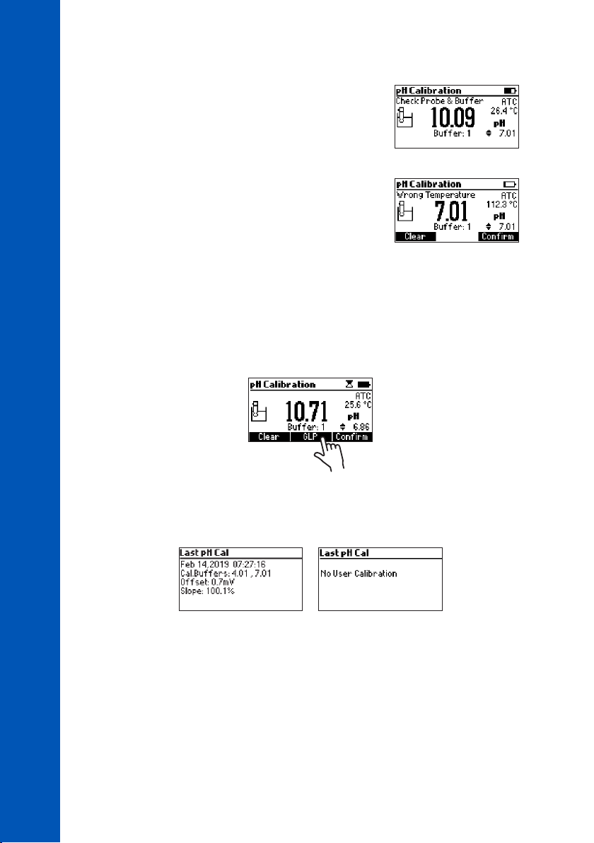
Check Probe & Buffer
There is a large difference between the pH measurement and
the selected buffer value or the electrode slope is outside of the
accepted slope limit. Clean the probe and confirm the correct
buffer selection.
PROBE MODE
Wrong Temperature
The buffer temperature is outside of the acceptable window for the
selected buffer value.
9.4. pH GLP
Good Laboratory Practice (GLP) refers to a quality control function used to ensure uniformity and
consistency of sensor calibrations and measurements. To view the GLP information, press the GLP key
from the probe measurement screen.
30
The pH GLP screen displays the date and time, buffers, slope and offset for the last calibration. If the
probe has not been calibrated, “No User Calibration” is displayed. Press the ESC key to return to the
measurement mode.
Page 31
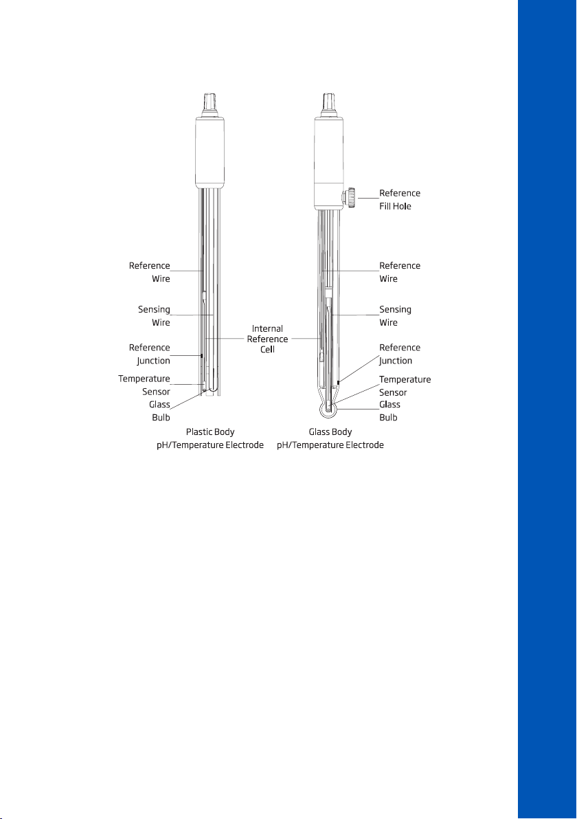
9.5. pH ELECTRODE CONDITIONING & MAINTENANCE
PROBE MODE
Remove the protective cap. Do not be alarmed if salt deposits are present, this is normal. Rinse the
probe with water.
Shake the electrode down as you would do with a clinical thermometer to eliminate any air bubbles
inside the glass bulb. If the bulb and / or junction are dry, soak the electrode in HI70300 or HI80300
Storage solution for a minimum of 30 minutes. Rinse with water. Calibrate before using.
For refillable electrodes if the filling solution (electrolyte) is more than 2½ cm (1”) below the fill hole,
add HI7082 or HI8082 3.5M KCl Electrolyte solution. Unscrew the fill hole cover during measurements
so the liquid reference junction maintains an outward flow of electrolyte.
Storage Procedure
To minimize clogging and ensure a quick response time, the glass bulb and the junction should be
kept moist and not allowed to dry out.
Replace the solution in the protective cap with a few drops of HI70300 or HI80300 Storage solution
or Filling solution (HI7082 or HI8082 3.5M KCl Electrolyte solution). pH 4.01 or 7.01 buffer can
also be used.
Note: Never store the electrode in distilled or deionized water.
31
Page 32

Periodic Maintenance
Inspect the electrode and the cable. The cable used for connection to the instrument must be intact and
there must be no points of broken insulation on the cable, connectors must be perfectly clean and dry.
If there are any scratches or cracks on the electrode stem or bulb, replace the electrode.
For refillable electrodes, refill the reference chamber with fresh electrolyte (HI7082 or HI8082 3.5M
PROBE MODE
KCl Electrolyte solution). Allow the electrode to stand upright for 1 hour.
Cleaning Procedure
Several cleaning solutions are available:
• General – Soak in Hanna HI7061 or HI8061 General cleaning solution for approximately
30 minutes.
• Protein –Soak in Hanna HI7073 or HI8073 Protein cleaning solution for 15 minutes.
• Inorganic – Soak in Hanna HI7074 Inorganic cleaning solution for 15 minutes.
• Oil and grease – Rinse with Hanna HI7077 or HI8077 Oil and Fat cleaning solution.
After performing any of the cleaning procedures, rinse the electrode thoroughly with distilled water,
refill the reference chamber with fresh electrolyte (refillable electrodes only) and soak the electrode in
HI70300 or HI80300 Storage solution for at least 1 hour before taking measurements.
Temperature Correlation for pH Sensitive Glass
Verify the temperature range by reading the limits on electrode’s cap. The pH electrode’s life is
temperature dependent. If constantly cycled between two temperatures, the life of the electrode is
drastically reduced.
32
Page 33
10. METHOD PROCEDURES
10.1. ALKALINITY
SPECIFICATIONS
Range 0 to 500 mg/L (as CaCO
Resolution 1 mg/L
Accuracy ±5 mg/L ±5% of reading at 25 °C
Light Source LED with narrow band interference filter @ 610 nm
Method Colorimetric Method
REQUIRED REAGENTS
Code Description Quantity
HI775S Alkalinity Reagent 1 mL
HI93755-53 Chlorine Removal Reagent 1 drop
REAGENT SETS
HI775-26 Reagents for 25 tests
For other accessories see ACCESSORIES section.
MEASUREMENT PROCEDURE
• Select the Alkalinity method using the procedure described in the METHOD SELECTION section.
)
3
METHOD PROCEDURES
ALKALINITY
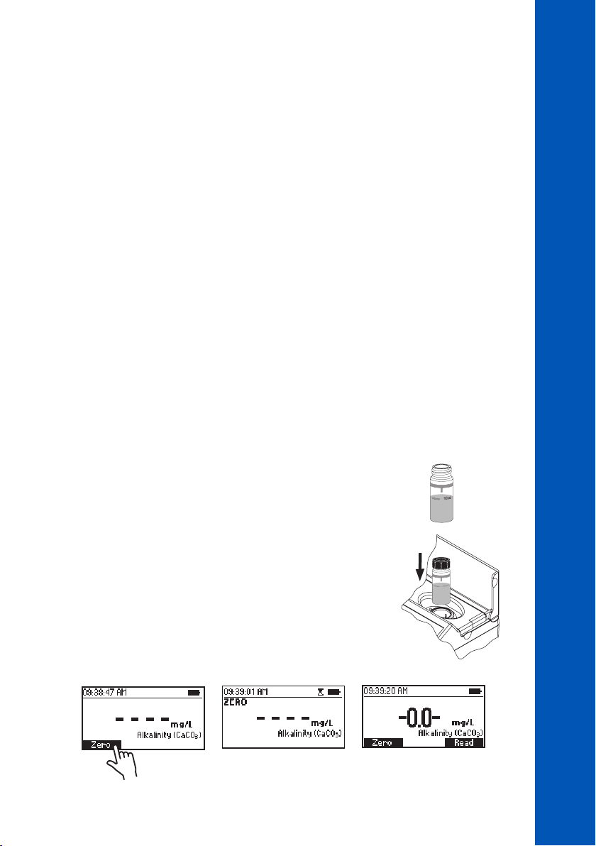
• Fill the cuvette with 10 mL of unreacted sample (up to the mark).
Replace the plastic stopper and the cap.
• Insert the cuvette into the holder and close the lid.
• Press Zero. The display will show “-0.0-” when the meter is zeroed and ready for measurement.
10 mL
33
33
33
Page 34
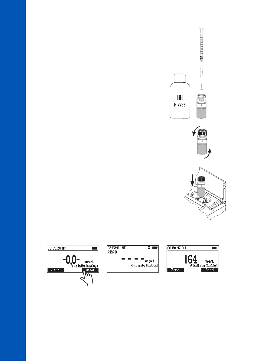
• Remove the cuvette.
ALKALINITY
METHOD PROCEDURES
• Add 1mL of HI775S Alkalinity Reagent to the sample
using a 1 mL syringe.
• Replace the plastic stopper and the cap. Invert 5 times.
• Insert the cuvette into the holder and close the lid.
• Press Read to start the reading. The instrument displays the results in mg/L calcium carbonate
(CaCO
).
3
1 mL
34
34
34
INTERFERENCES
Interference may be caused by:
• Chlorine must be absent, to remove the interference add one drop of HI93755-53 Chlorine Removal
Reagent to the unreacted sample
Page 35
10.2. ALKALINITY, MARINE
SPECIFICATIONS
Range 0 to 300 mg/L (as CaCO
Resolution 1 mg/L
Accuracy ±5 mg/L ±5% of reading at 25 °C
Light Source LED with narrow band interference filter @ 610 nm
Method Colorimetric Method
REQUIRED REAGENTS
Code Description Quantity
HI755S Alkalinity Reagent 1 mL
REAGENT SETS
HI755-26 Reagents for 25 tests
For other accessories see ACCESSORIES section.
MEASUREMENT PROCEDURE
• Select the Alkalinity Marine method using the procedure described in the METHOD SELECTION
section.
)
3
METHOD PROCEDURES
ALKALINITY, MARINE
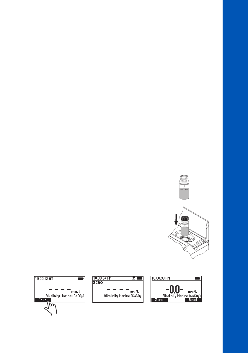
• Fill the cuvette with 10 mL of unreacted sample (up to the mark).
Replace the plastic stopper and the cap.
• Insert the cuvette into the holder and close the lid.
• Press Zero. The display will show “-0.0-” when the meter is zeroed and ready for measurement.
10 mL
35
35
35
Page 36
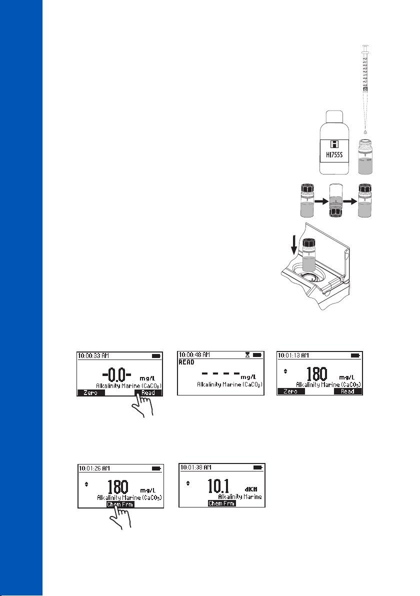
• Remove the cuvette.
1 mL
ALKALINITY, MARINE
• Add 1 mL of HI755S Alkalinity Reagent to the sample using a 1mL syringe.
METHOD PROCEDURES
• Replace the plastic stopper and the cap. Invert 5 times.
• Insert the cuvette into the holder and close the lid.
• Press Read to start the reading. The instrument displays the results in mg/L as calcium carbonate
).
(CaCO
3
• Press the or key to access the second level functions.
36
36
36
• Press Chem Frm to convert the result to degree KH (dKH).
• Press the or key to return to the measurement screen.
Page 37

10.3. ALUMINUM
METHOD PROCEDURES
ALUMINUM
SPECIFICATIONS
Range 0.00 to 1.00 mg/L (as Al
Resolution 0.01 mg/L
Accuracy ±0.04 mg/L ±4% of reading at 25 °C
Light Source LED with narrow band interference filter @ 525 nm
Method Adaptation of the Aluminon Method
REQUIRED REAGENTS
Code Description Quantity
HI93712A-0 Aluminum Reagent A 1 packet
HI93712B-0 Aluminum Reagent B 1 packet
HI93712C-0 Aluminum Reagent C 1 packet
REAGENT SETS
HI93712-01 Reagents for 100 tests
HI93712-03 Reagents for 300 tests
For other accessories see ACCESSORIES section.
MEASUREMENT PROCEDURE
• Select the Aluminum method using the procedure described in the METHOD SELECTION section.
• Fill a graduated beaker with 50 mL of sample.
3+
)
• Add one packet of HI93712A-0 Aluminum Reagent A and mix
until completely dissolved.
• Add one packet of HI93712B-0 Aluminum Reagent B and mix
until completely dissolved.
37
37
37
Page 38
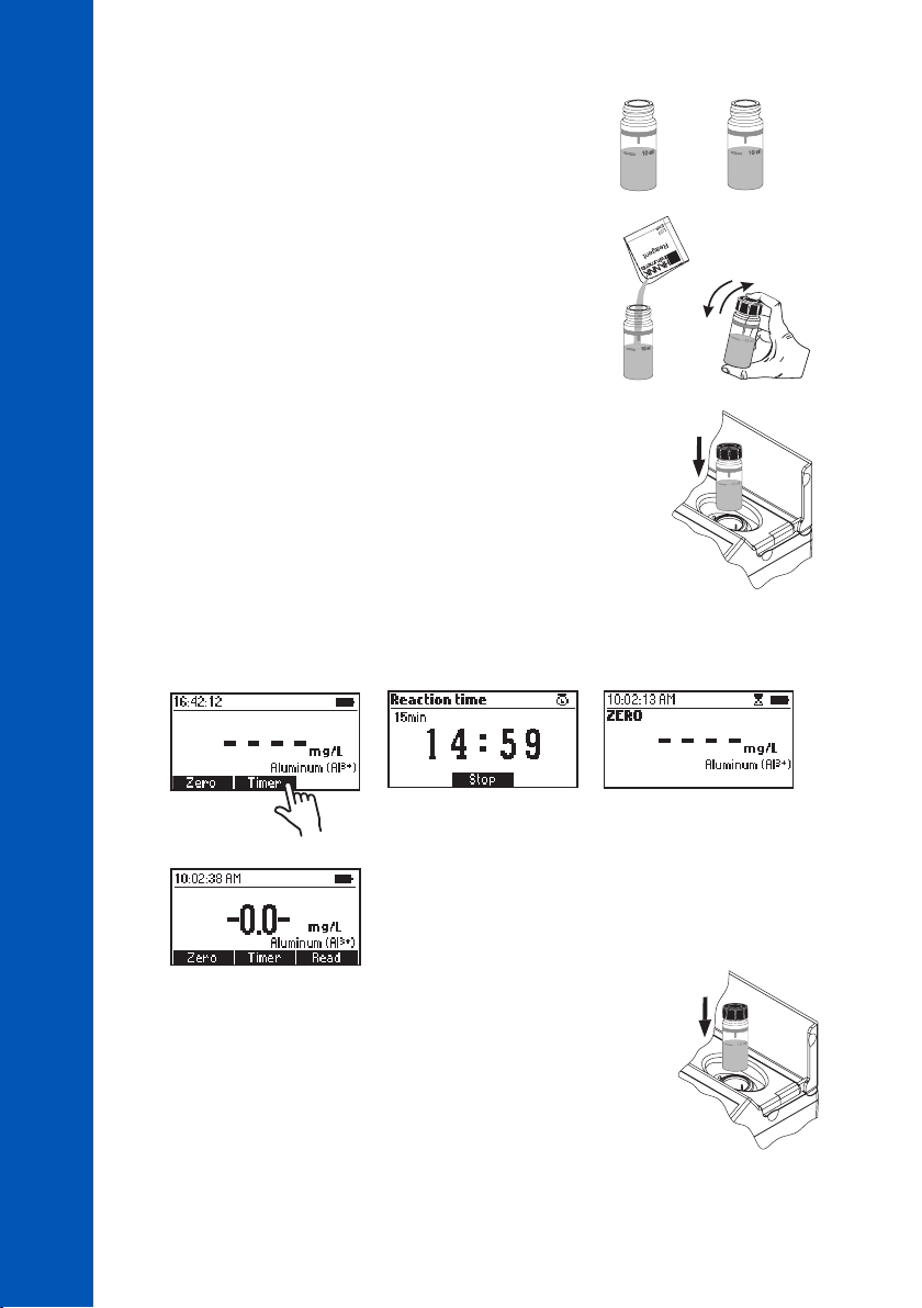
• Fill two cuvettes with 10 mL of sample (up to the mark).
ALUMINUM
• Add one packet of HI93712C-0 Aluminum Reagent C to one
cuvette (#1). Replace the plastic stopper and the cap. Shake
gently until completely dissolved. This is the blank.
METHOD PROCEDURES
• Insert the first cuvette (#1) into the holder and close the lid.
• Press Timer and the display will show the countdown prior to the zero or wait 15 minutes and then
press Zero. The display will show “-0.0-“ when the meter is zeroed and ready for measurement.
# 1
10 mL
# 1
# 1
10 mL
# 2
38
38
38
• Remove the blank and insert the second cuvette (#2) into the
holder and close the lid.
# 2
Page 39
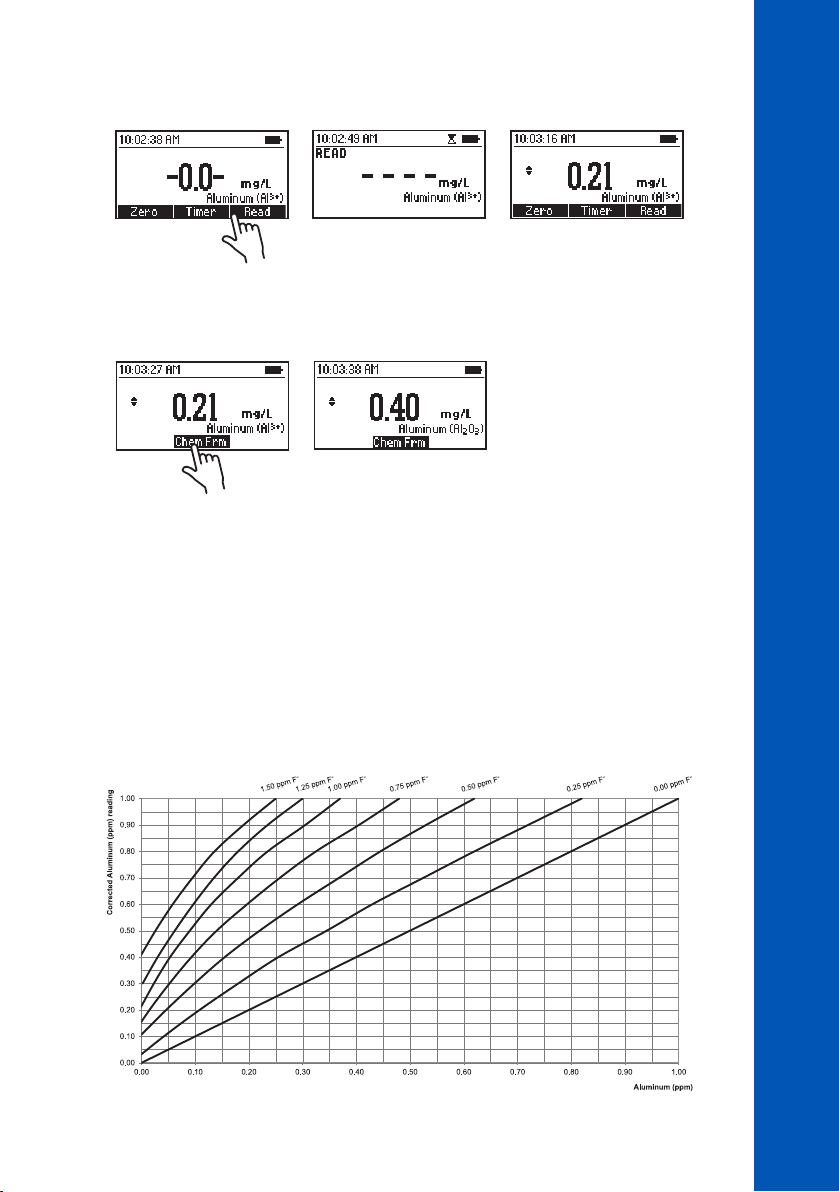
• Press Read to start the reading. The instrument displays the results in mg/L of aluminum (Al3+).
• Press the or key to access the second level functions.
METHOD PROCEDURES
ALUMINUM
• Press Chem Frm to convert the result to mg/L of aluminum oxide (Al
• Press the or key to return to the measurement screen.
INTERFERENCES
Interference may be caused by:
• Alkalinity above 1000 mg/L
• Phosphate above 50 mg/L
• Iron above 20 mg/L
• Fluoride must be absent. If the fluoride concentration is known, the aluminum concentration can
be determined using the graph below:
2O3
).
39
39
39
Page 40

To use the fluoride interference graph:
1. Follow the measurement procedure to obtain the aluminum concentration.
2. Locate the aluminum reading on x-axis.
3. Follow the line up, until it intersects the fluoride curve corresponding to the fluoride concentration
ALUMINUM
METHOD PROCEDURES
in the sample.
4. From the intersection of the fluoride and aluminum line, follow the line to the left until it
intersects the y-axis. This point corresponds to the corrected aluminum concentration in the
sample.
E.g. Aluminum reading on meter 0.40 ppm and fluoride content in sample 0.50 ppm, corrected
aluminum concentration in sample is 0.75 ppm.
40
40
40
Page 41
10.4. AMMONIA LOW RANGE
SPECIFICATIONS
Range 0.00 to 3.00 mg/L (as NH
Resolution 0.01 mg/L
Accuracy ±0.04 mg/L ±4% of reading at 25 °C
Light Source LED with narrow band interference filter @ 420 nm
Method Adaptation of the ASTM Manual of Water and Environmental Technology,
D1426 Nessler Method
REQUIRED REAGENTS
Code Description Quantity
HI93700A-0 Ammonia Low Range Reagent A 4 drops
HI93700B-0 Ammonia Low Range Reagent B 4 drops
REAGENT SETS
HI93700-01 Reagents for 100 tests
HI93700-03 Reagents for 300 tests
For other accessories see ACCESSORIES section.
MEASUREMENT PROCEDURE
• Select the Ammonia LR method using the procedure described in the METHOD SELECTION section.
-N)
3
METHOD PROCEDURES
AMMONIA LOW RANGE
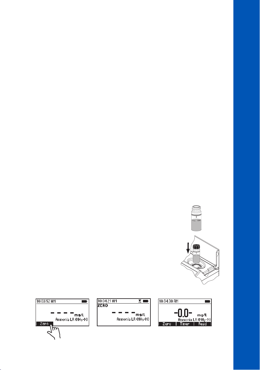
• Fill the cuvette with 10 mL of unreacted sample (up to the mark).
Replace the plastic stopper and the cap.
• Insert the cuvette into the holder and close the lid.
• Press Zero. The display will show “-0.0-” when the meter is zeroed and ready for measurement.
10 mL
41
41
41
Page 42
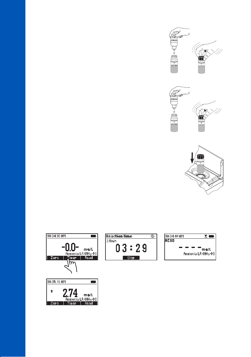
• Remove the cuvette.
• Add 4 drops of HI93700A-0 Ammonia Low Range Reagent
A. Replace the plastic stopper and the cap. Swirl to mix the
solution.
METHOD PROCEDURES
AMMONIA LOW RANGE
• Add 4 drops of HI93700B-0 Ammonia Low Range Reagent
B. Replace the plastic stopper and the cap. Swirl to mix the
solution.
• Insert the cuvette into the holder and close the lid.
• Press Timer and the display will show the countdown prior to the measurement or wait 3 minutes
and 30 seconds and press Read. When the timer ends the meter will perform the reading. The
instrument displays the results in mg/L of ammonia nitrogen (NH
-N).
3
×4
×4
42
42
42
• Press the or key to access the second level functions.
Page 43

• Press Chem Frm to convert the result to mg/L of ammonia (NH3) and ammonium (NH
• Press the or key to return to the measurement screen.
INTERFERENCES
Interference may be caused by:
• Hardness above 1 g/L
• Iron
• Sulfide may cause turbidity
• Organic compounds like acetone above 0.1%, alcohols, aldehydes, aliphatic and aromatic amines,
chloramines, glycine, or urea above 10 mg/L, to remove the interference distillation is required
+
).
4
METHOD PROCEDURES
AMMONIA LOW RANGE
43
43
43
Page 44
10.5. AMMONIA MEDIUM RANGE
SPECIFICATIONS
Range 0.00 to 10.00 mg/L (as NH
Resolution 0.01 mg/L
Accuracy ±0.05 mg/L ±5% of reading at 25 °C
Light Source LED with narrow band interference filter @ 420 nm
Method Adaptation of the ASTM Manual of Water and Environmental Technology,
D1426, Nessler Method
-N)
3
METHOD PROCEDURES
AMMONIA MEDIUM RANGE
REQUIRED REAGENTS
Code Description Quantity
HI93715A-0 Ammonia Medium Range Reagent A 4 drops
HI93715B-0 Ammonia Medium Range Reagent B 4 drops
REAGENT SETS
HI93715-01 Reagents for 100 tests
HI93715-03 Reagents for 300 tests
For other accessories see ACCESSORIES section.
MEASUREMENT PROCEDURE
• Select the Ammonia MR method using the procedure described in the METHOD SELECTION section.
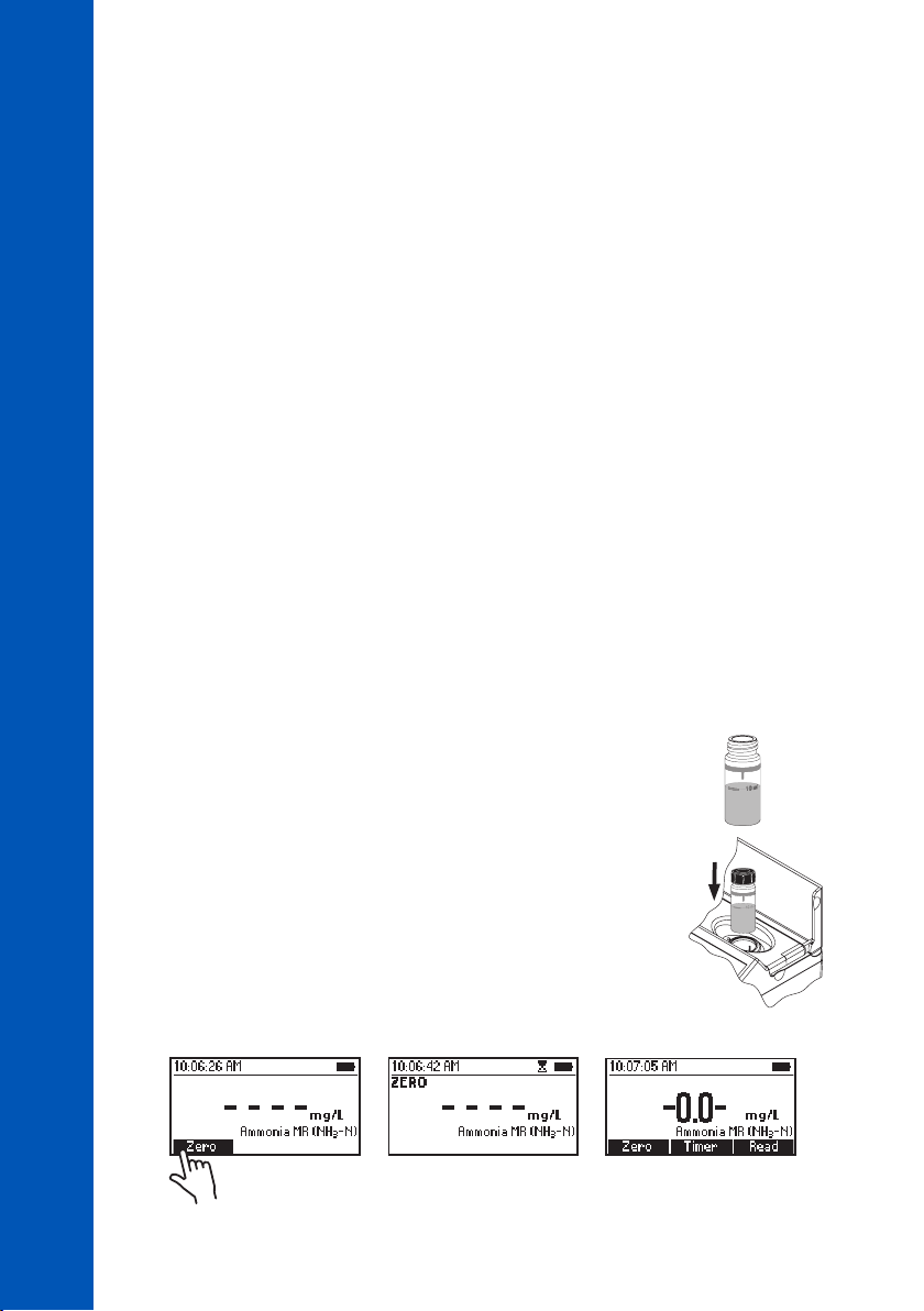
• Fill the cuvette with 10 mL of unreacted sample (up to the mark).
Replace the plastic stopper and the cap.
• Insert the cuvette into the holder and close the lid.
10 mL
44
44
44
• Press Zero. The display will show “-0.0-” when the meter is zeroed and ready for measurement.
Page 45
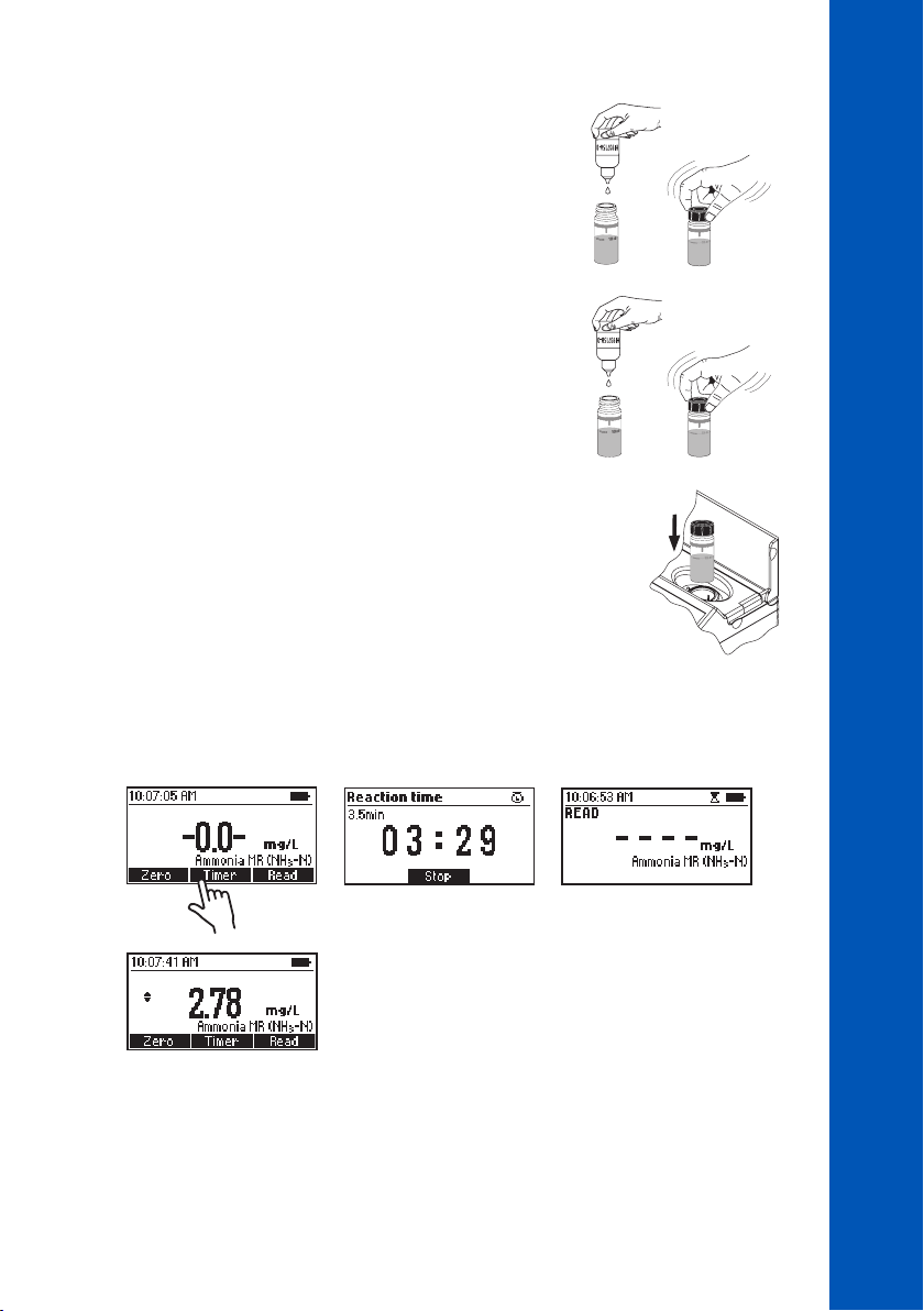
• Remove the cuvette.
METHOD PROCEDURES
AMMONIA MEDIUM RANGE
• Add 4 drops of HI93715A-0 Ammonia Medium Range Reagent A.
×4
Replace the plastic stopper and the cap. Swirl to mix the solution.
• Add 4 drops of HI93715B-0 Ammonia Medium Range Reagent B.
×4
Replace the plastic stopper and the cap. Swirl to mix the solution.
• Insert the cuvette into the holder and close the lid.
• Press Timer and the display will show the countdown prior to the measurement or wait 3 minutes
and 30 seconds and press Read. When the timer ends the meter will perform the reading. The
instrument displays the results in mg/L of ammonia nitrogen (NH
-N).
3
• Press the or key to access the second level functions.
45
45
45
Page 46

• Press Chem Frm to convert the result to mg/L of ammonia (NH3) and ammonium (NH
• Press the or key to return to the measurement screen.
METHOD PROCEDURES
INTERFERENCES
AMMONIA MEDIUM RANGE
Interference may be caused by:
• Hardness above 1 g/L
• Iron
• Sulfide may cause turbidity
• Organic compounds like acetone above 0.1%, alcohols, aldehydes, aliphatic and aromatic amines,
chloramines, glycine, or urea above 10 mg/L, to remove the interference distillation is required
+
).
4
46
46
46
Page 47
10.6. AMMONIA HIGH RANGE
SPECIFICATIONS
Range 0.0 to 100.0 mg/L (as NH
Resolution 0.1 mg/L
Accuracy ±0.5 mg/L ±5% of reading at 25 °C
Light Source LED with narrow band interference filter @ 420 nm
Method Adaptation of the ASTM Manual of Water and Environmental Technology,
D1426, Nessler Method
REQUIRED REAGENTS
Code Description Quantity
HI93733A-0 Ammonia High Range Reagent A 4 drops
HI93733B-0 Ammonia High Range Reagent B 9 mL
REAGENT SETS
HI93733-01 Reagents for 100 tests
HI93733-03 Reagents for 300 tests
For other accessories see ACCESSORIES section.
MEASUREMENT PROCEDURE
• Select the Ammonia HR method using the procedure described in
the METHOD SELECTION section.
-N)
3
METHOD PROCEDURES
AMMONIA HIGH RANGE
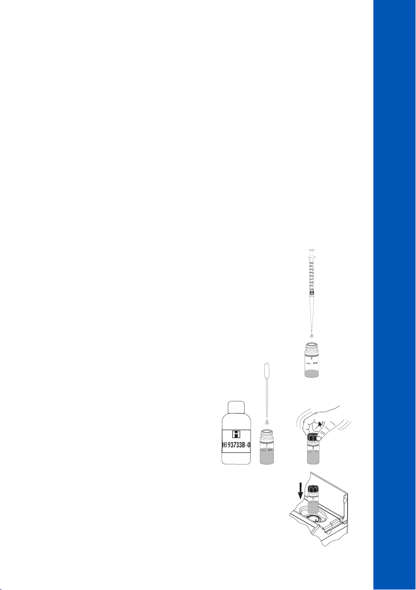
• Add 1 mL of unreacted sample to the cuvette using a 1 mL syringe.
• Use the pipette to fill the cuvette up to the 10
mL mark with HI93733B-0 Ammonia High
Range Reagent B. Replace the plastic stopper
and the cap. Swirl to mix the solution.
• Insert the cuvette into the holder and close the lid.
10 mL
1 mL
47
47
47
Page 48
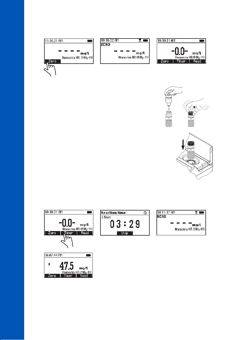
• Press Zero. The display will show “-0.0-” when the meter is zeroed and ready for measurement.
• Remove the cuvette.
METHOD PROCEDURES
AMMONIA HIGH RANGE
• Add 4 drops of HI93733A-0 Ammonia High Range Reagent A.
Replace the plastic stopper and the cap. Swirl to mix the solution.
• Insert the cuvette into the holder and close the lid.
• Press Timer and the display will show the countdown prior to the measurement or wait 3 minutes
and 30 seconds and press Read. When the timer ends the meter will perform the reading. The
instrument displays the results in mg/L of ammonia nitrogen (NH
-N).
3
×4
48
48
48
• Press the or key to access the second level functions.
Page 49

• Press Chem Frm to convert the result to mg/L of ammonia (NH3) and ammonium (NH
• Press the or key to return to the measurement screen.
INTERFERENCES
Interference may be caused by:
• Hardness above 1 g/L
• Iron
• Sulfide may cause turbidity
• Organic compounds like acetone above 0.1%, alcohols, aldehydes, aliphatic and aromatic amines,
chloramines, glycine, or urea above 10 mg/L, to remove the interference distillation is required
+
).
4
METHOD PROCEDURES
AMMONIA HIGH RANGE
49
49
49
Page 50
10.7. BROMINE
SPECIFICATIONS
Range 0.00 to 8.00 mg/L (as Br
BROMINE
Resolution 0.01 mg/L
Accuracy ±0.08 mg/L ±3% of reading at 25 °C
Light Source LED with narrow band interference filter @ 525 nm
Method Adaptation of Standard Methods for the Examination of Water and
Wastewater, 18th Edition, DPD Method
)
2
METHOD PROCEDURES
REQUIRED REAGENTS
Code Description Quantity
HI93716-0 Bromine Reagent 1 packet
REAGENT SETS
HI93716-01 Reagents for 100 tests
HI93716-03 Reagents for 300 tests
For other accessories see ACCESSORIES section.
MEASUREMENT PROCEDURE
• Select the Bromine method using the procedure described in the METHOD SELECTION section.
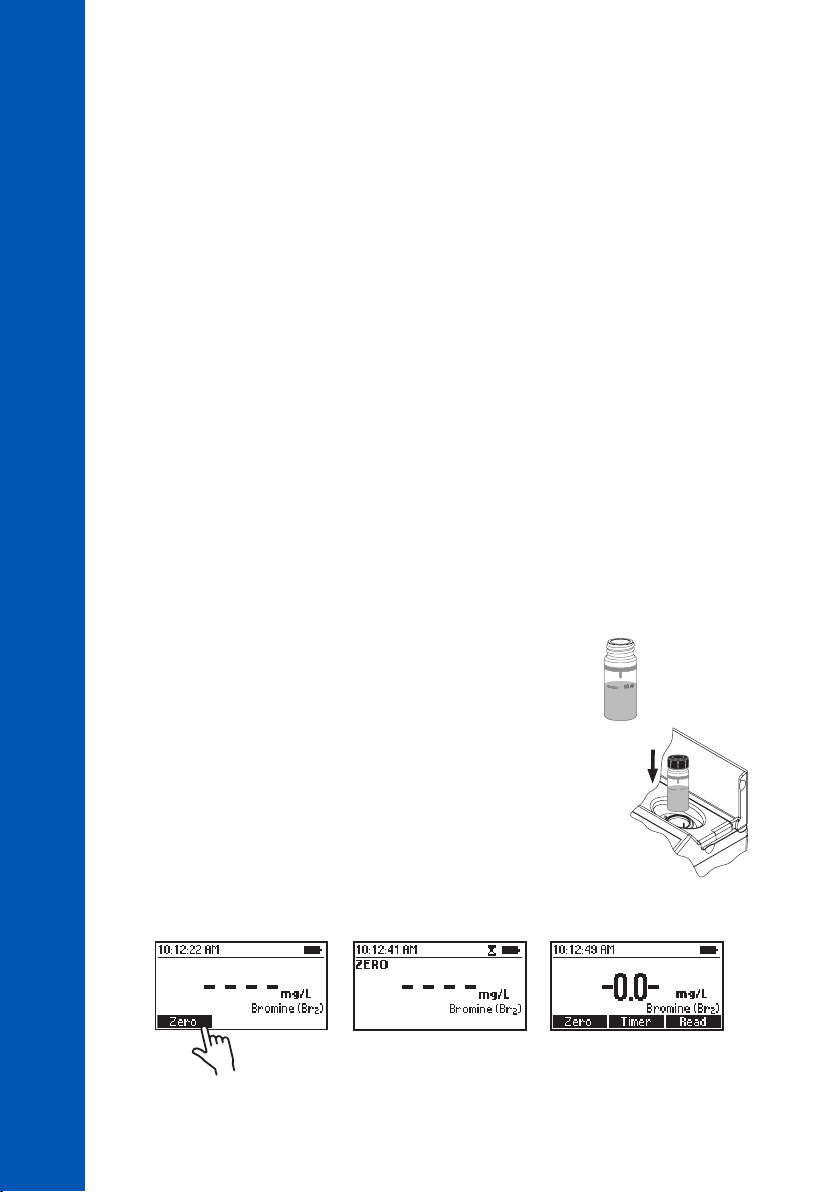
• Fill the cuvette with 10 mL of unreacted sample (up to the mark).
Replace the plastic stopper and the cap.
• Insert the cuvette into the holder and close the lid.
• Press Zero. The display will show “-0.0-” when the meter is zeroed and ready for measurement.
10 mL
50
50
50
Page 51
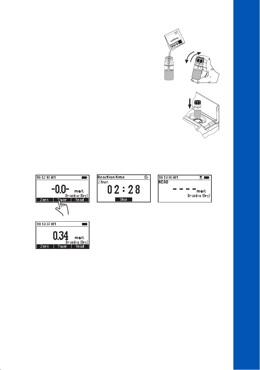
• Remove the cuvette.
• Add one packet of HI93716-0 Bromine Reagent. Replace the
plastic stopper and the cap. Shake gently for about 20 seconds to
dissolve most of the reagent.
• Insert the cuvette into the holder and close the lid.
• Press Timer and the display will show the countdown prior to the measurement or wait 2 minutes
and 30 seconds and press Read. When the timer ends the meter will perform the reading. The
instrument displays the results in mg/L of bromine (Br
).
2
METHOD PROCEDURES
BROMINE
INTERFERENCES
Interference may be caused by:
• Chlorine, Iodine, Ozone, Oxidized forms of Chromium and Manganese
• Hardness greater than 500 mg/L CaCO3, to remove the interference shake the sample for
approximately 1 minute after adding the reagent
• Alkalinity greater than 300 mg/L CaCO3 or acidity greater than 150 mg/L CaCO3, the color of the
sample may develop only partially or rapidly fade, to remove the interference neutralize the sample
with diluted HCl or NaOH
51
51
51
Page 52
10.8. CALCIUM
SPECIFICATIONS
CALCIUM
METHOD PROCEDURES
Range 0 to 400 mg/L (as Ca
Resolution 1 mg/L
Accuracy ±10 mg/L ±5% of reading at 25 °C
Light Source LED with narrow band interference filter @ 466 nm
Method Adaptation of the Oxalate Method
REQUIRED REAGENTS
Code Description Quantity
– Buffer Reagent 4 drops
HI93752A-Ca Calcium Reagent A 7 mL
HI93752B-Ca Calcium Reagent B 1 mL
REAGENT SETS
HI937521-01 Reagents for 50 tests
HI937521-03 Reagents for 150 tests
For other accessories see ACCESSORIES section.
MEASUREMENT PROCEDURE
• Select the Calcium method using the procedure described in the METHOD SELECTION section.
2+
)
52
52
52
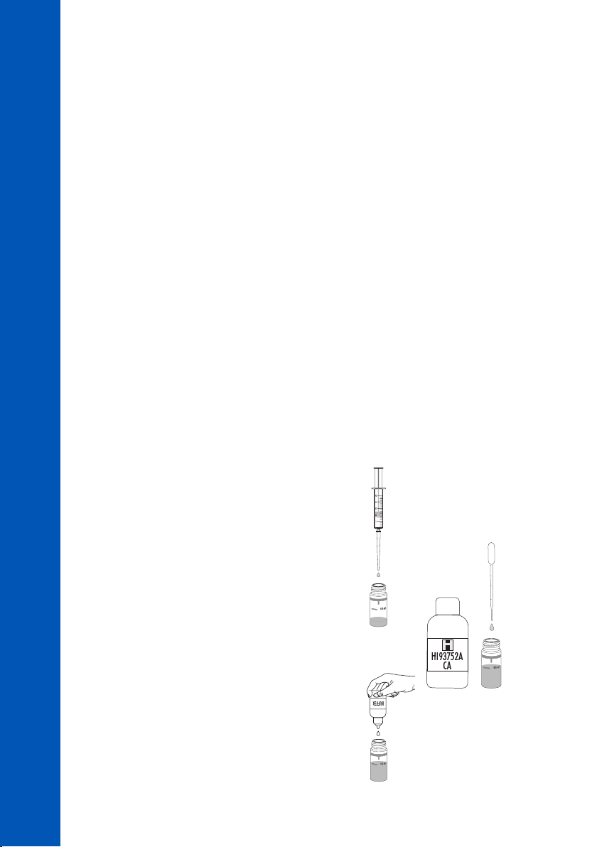
• Add 3 mL of unreacted sample to the cuvette using the
5 mL syringe.
3 mL
• Use the pipette to fill the cuvette up to the 10 mL mark
with the HI93752A-Ca Calcium Reagent A.
10 mL
×4
• Add 4 drops of Buffer Reagent.
Page 53
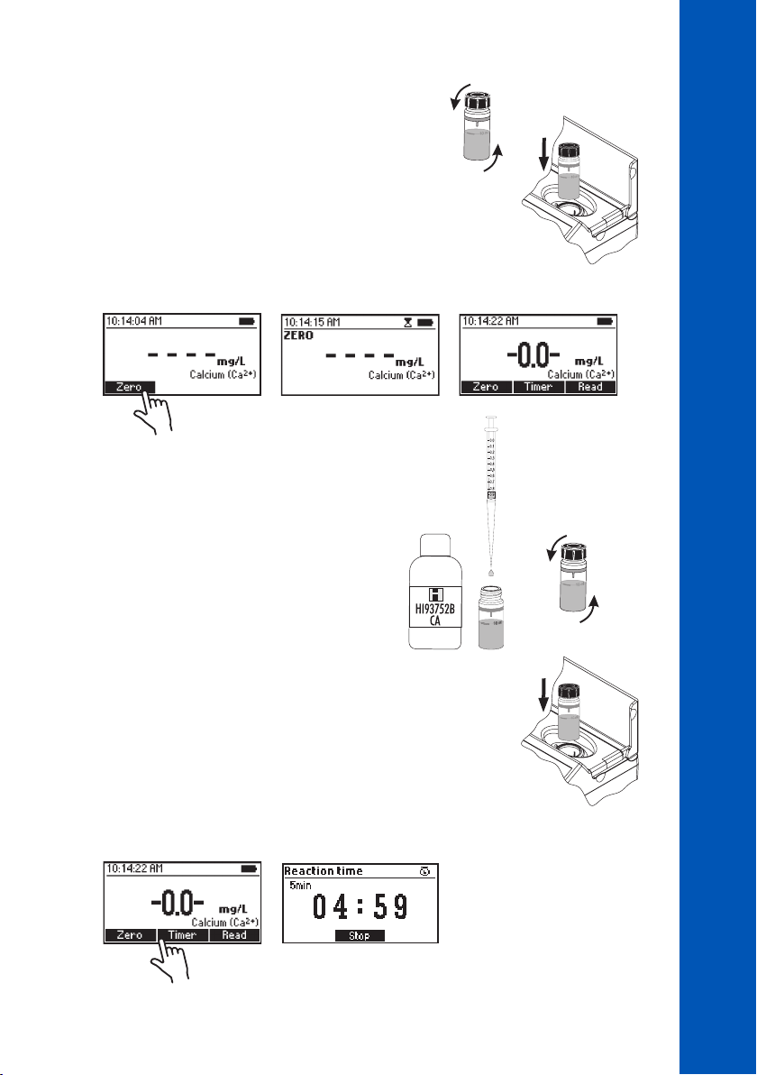
• Replace the plastic stopper and the cap. Invert several
times to mix.
• Insert the cuvette into the holder and close the lid.
• Press Zero. The display will show “-0.0-” when the meter is zeroed and ready for measurement.
• Remove the cuvette.
• Add 1 mL of HI93752B-Ca Calcium Reagent B to
the sample using the 1 mL syringe. Replace the
plastic stopper and the cap. Invert the cuvette 10
times to mix (about 15 seconds).
1 mL
METHOD PROCEDURES
CALCIUM
• Insert the cuvette into the holder and close the lid.
• Press Timer and the display will show the countdown prior to the measurement or wait 5 minutes.
53
53
53
Page 54
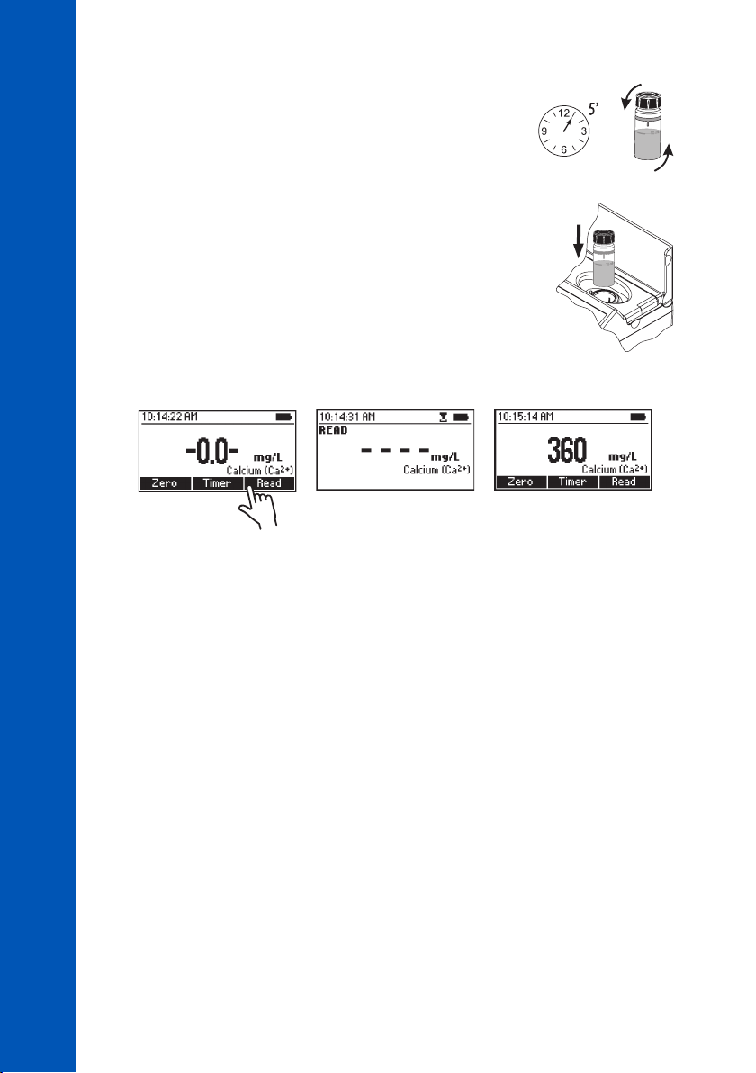
• After waiting 5 minutes, invert the cuvette 10 times to mix (about
CALCIUM
15 seconds).
• Insert the cuvette into the holder and close the lid.
METHOD PROCEDURES
• Press Read to start the reading. The instrument displays the results in mg/L of calcium (Ca
INTERFERENCES
Interference may be caused by:
• Acidity, Alkalinity above 1000 mg/ L CaCO
• Magnesium above 400 mg/L
3
2+
).
54
54
54
Page 55
10.9. CALCIUM, MARINE
METHOD PROCEDURES
CALCIUM, MARINE
SPECIFICATIONS
Range 200 to 600 mg/L (as Ca
Resolution 1 mg/L
Accuracy ±6% of reading at 25 °C
Light Source LED with narrow band interference filter @ 610 nm
Method Adaptation of the Zincon Method
REQUIRED REAGENTS
Code Description Quantity
HI7581 Calcium Reagent A 1 mL
HI7582 Calcium Reagent B 1 packet
REAGENT SETS
HI758-26 Reagents for 25 tests
For other accessories see ACCESSORIES section.
MEASUREMENT PROCEDURE
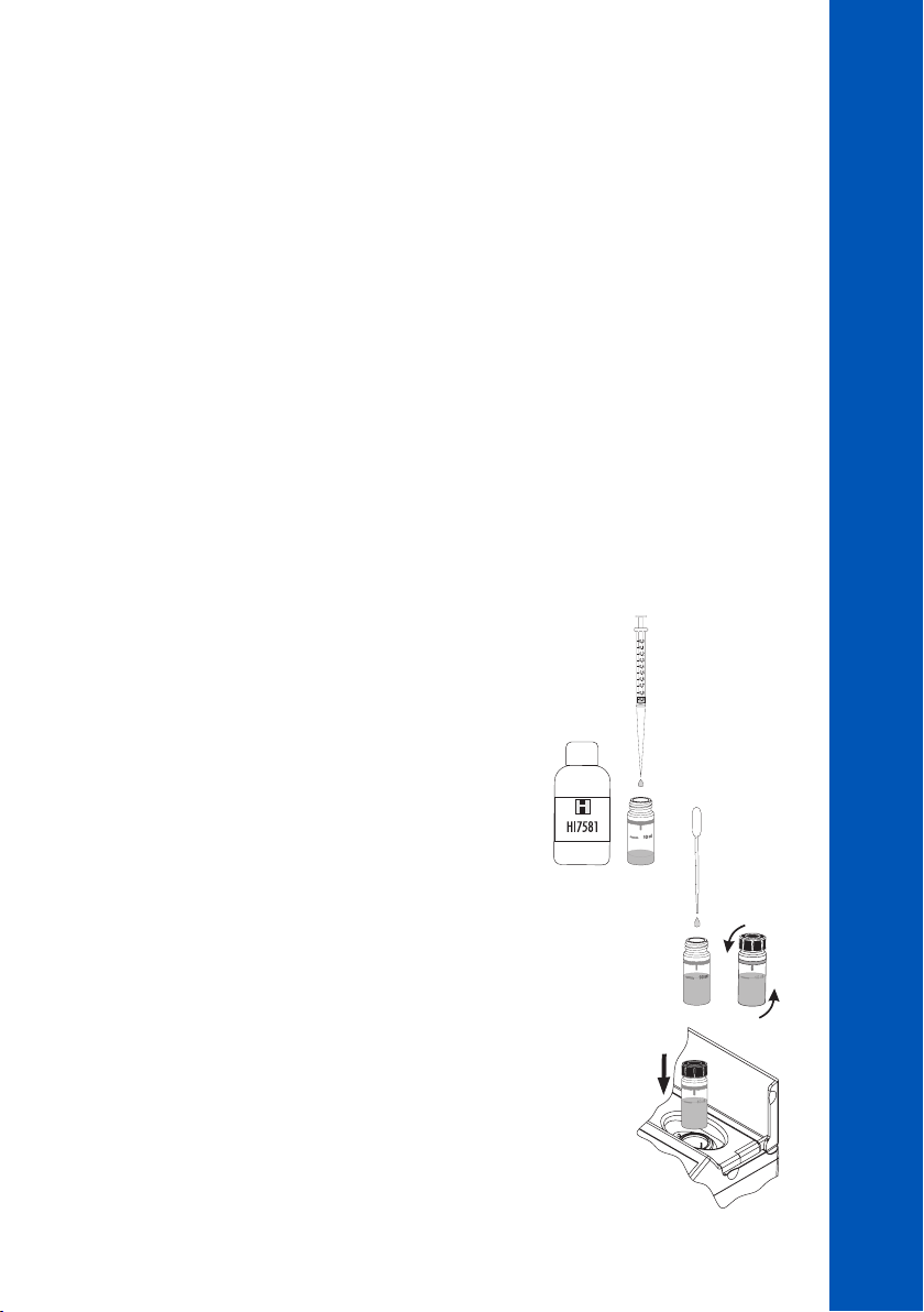
• Select the Calcium Marine method using the procedure
described in the METHOD SELECTION section.
• Add 1 mL of HI7581 Calcium Reagent A to the cuvette using
a 1 mL syringe.
2+
)
1 mL
• Use the plastic pipette to fill the cuvette to the 10 mL mark
with deionized water. Replace the plastic stopper and the cap.
Invert 3 to 5 times to mix.
• Insert the cuvette into the holder and close the lid.
10 mL
55
55
55
Page 56
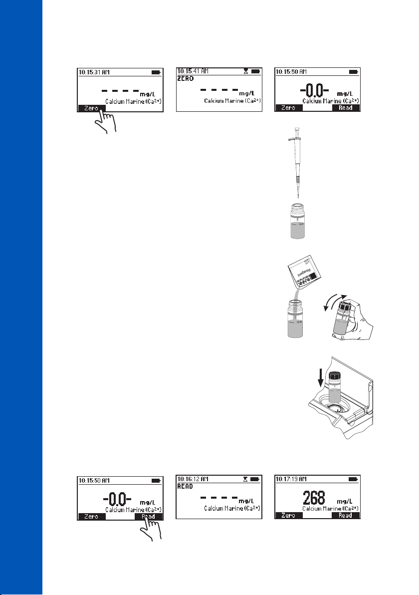
• Press Zero. The display will show “-0.0-” when the meter is zeroed and ready for measurement.
CALCIUM, MARINE
• Remove the cuvette.
METHOD PROCEDURES
• Use the minipipette to add 0.1 mL of sample to the cuvette.
• Add one packet of HI7582 Calcium Reagent B. Replace
the plastic stopper and the cap and shake vigorously for
15 seconds or until the powder is completely dissolved.
Allow air bubbles to dissipate for 15 seconds before taking
a reading.
0.1 mL
56
56
56
• Insert the cuvette into the holder and close the lid.
• Press Read to start the reading. The instrument displays the results in mg/L of calcium (Ca
2+
).
Page 57

10.10. CHLORIDE
METHOD PROCEDURES
CHLORIDE
SPECIFICATIONS
Range 0.0 to 20.0 mg/L (as Cl
Resolution 0.1 mg/L
Accuracy ±0.5 mg/L ±6% of reading at 25 °C
Light Source LED with narrow band interference filter @ 466 nm
Method Adaptation of the Mercury(II) Thiocyanate Method
REQUIRED REAGENTS
Code Description Quantity
HI93753A-0 Chloride Reagent A 1 mL
HI93753B-0 Chloride Reagent B 1 mL
REAGENT SETS
HI93753-01 Reagents for 100 tests
HI93753-03 Reagents for 300 tests
For other accessories see ACCESSORIES section.
MEASUREMENT PROCEDURE
• Select the Chloride method using the procedure described in the METHOD SELECTION section.
• Fill one cuvette (#1) with 10 mL of deionized water (up to the
mark).
-
)
#1
10 mL
• Fill a second cuvette (#2) with 10 mL of sample (up to the mark).
Note: For samples with low chloride ion concentration, rinse the cuvette a few times with sample
before filling it with 10 mL of sample. For the most accurate results, use two graduated pipettes
to deliver exactly 10 mL of deionized water and 10 mL of sample to the cuvettes.
#2
10 mL
57
57
57
Page 58
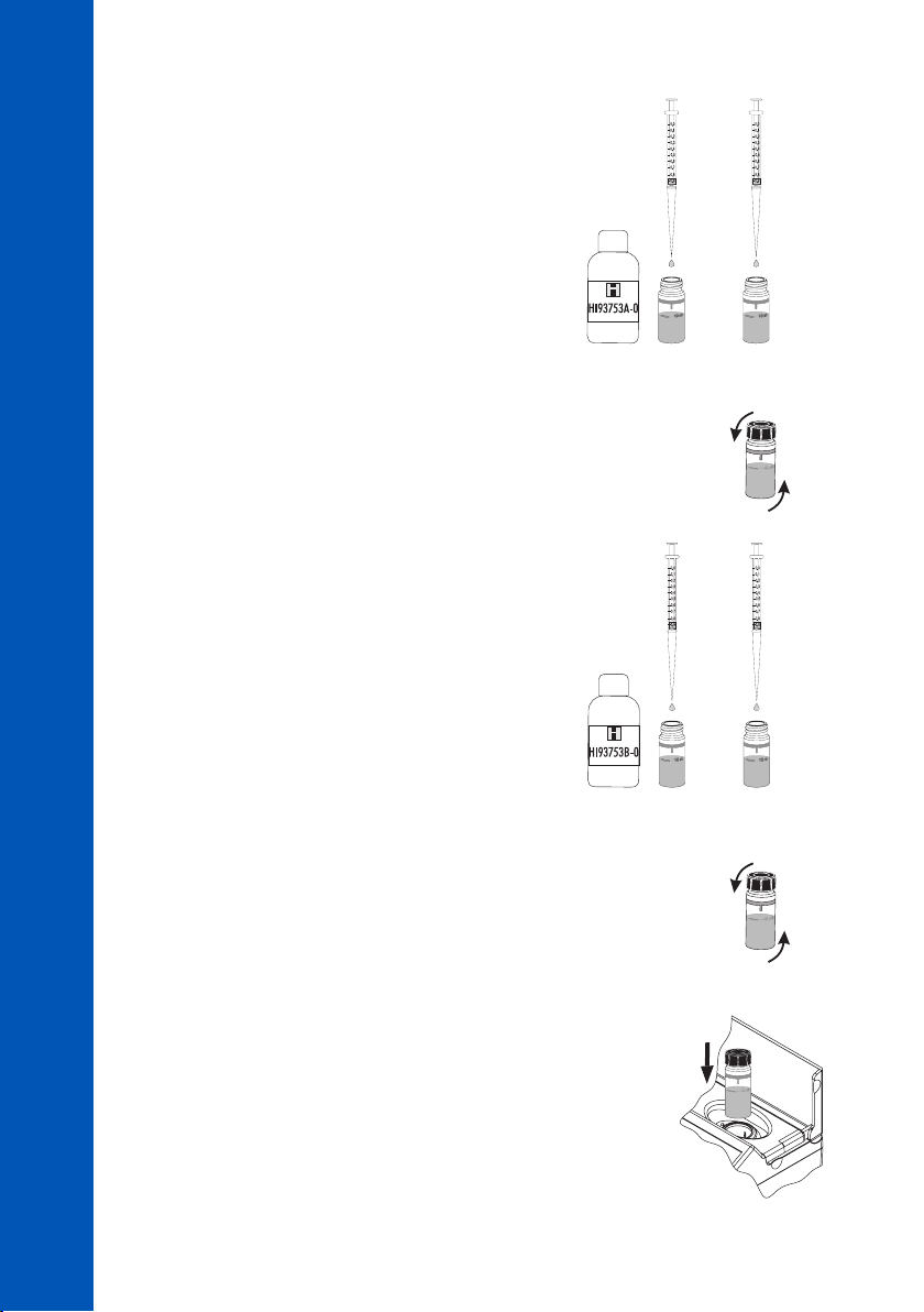
CHLORIDE
• Add 0.5 mL of HI93753A-0 Chloride Reagent A to each
cuvette using the 1 mL syringe.
METHOD PROCEDURES
• Replace the plastic stoppers and the caps. Mix each
cuvette by inverting for approximately 30 seconds.
• Add 0.5 mL of HI93753B-0 Chloride Reagent B to each
cuvette using the second 1 mL syringe.
#1
0.5 mL#20.5 mL
#1
0.5 mL#20.5 mL
58
58
58
• Replace the plastic stoppers and the caps. Mix each
cuvette by inverting for approximately 30 seconds.
• Insert the cuvette with the reacted deionized water (#1)
into the holder and close the lid.
#1
Page 59
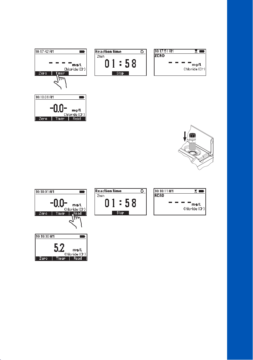
• Press Timer and the display will show the countdown prior to the zero or wait 2 minutes and press
Zero. The display will show "-0.0-" when the meter is zeroed and ready for measurement.
METHOD PROCEDURES
CHLORIDE
• Remove the cuvette.
• Insert the other cuvette (#2) with the reacted sample into the
holder and close the lid.
• Press Read to start reading. The instrument displays the results in mg/L of chloride (Cl
INTERFERENCES
Interference may be caused by:
• Intensely colored samples, samples should be adequately treated before performing the test
• Suspended matter in large amount should be removed by prior filtration
• Alkaline samples, neutralize before adding reagents, the pH of the sample after addition of
reagents should be about 2
#2
-
).
59
59
59
Page 60

10.11. CHLORINE DIOXIDE
SPECIFICATIONS
Range 0.00 to 2.00 mg/L (as ClO
Resolution 0.01 mg/L
Accuracy ±0.10 mg/L ±5% of reading at 25 °C
Light Source LED with narrow band interference filter @ 575 nm
Method Adaptation of the Chlorophenol Red Method
CHLORINE DIOXIDE
METHOD PROCEDURES
REQUIRED REAGENT
Code Description Quantity
HI93738A-0 Chlorine Dioxide Reagent A 1 mL
HI93738B-0 Chlorine Dioxide Reagent B 1 packet
HI93738C-0 Chlorine Dioxide Reagent C 1 mL
HI93738D-0 Chlorine Dioxide Reagent D 1 mL
REAGENT SETS
HI93738-01 Reagents for 100 tests
HI93738-03 Reagents for 300 tests
For other accessories see ACCESSORIES section.
SAMPLING PROCEDURE
It is recommended to analyze Chlorine Dioxide samples immediately after collection. Chlorine Dioxide
samples must be stored in sealed dark glass bottles, with minimal head space. Excessive heat (above
25 °C / 77 °F), agitation and exposure to light must be avoided.
)
2
60
60
60
MEASUREMENT PROCEDURE
• Select the Chlorine Dioxide method using the procedure described in the METHOD SELECTION
section.
• Fill two graduated mixing cylinders (#1 & #2) up to the 25 mL mark with the sample.
#1
25 ml
#2
25 ml
Page 61
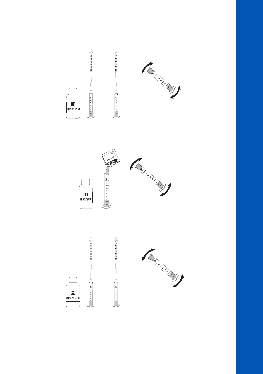
• Add 0.5 mL of HI93738A-0 Chlorine Dioxide Reagent A to each cylinder (#1 & #2), using a
1 mL syringe, cap them and invert several times to mix.
#1 & #2
METHOD PROCEDURES
CHLORINE DIOXIDE
#1
0.5 mL
#2
0.5 mL
• Add one packet of HI93738B-0 Chlorine Dioxide Reagent B to one of the two cylinders (#1), cap
and invert it several times until it is totally dissolved. This is the blank.
#1
• Add 0.5 mL of HI93738C-0 Chlorine Dioxide Reagent C to each cylinder (#1 & #2), using a 1 mL
syringe, cap them and invert several times to mix.
#1 & #2
#1
0.5 mL
#2
0.5 mL
61
61
61
Page 62
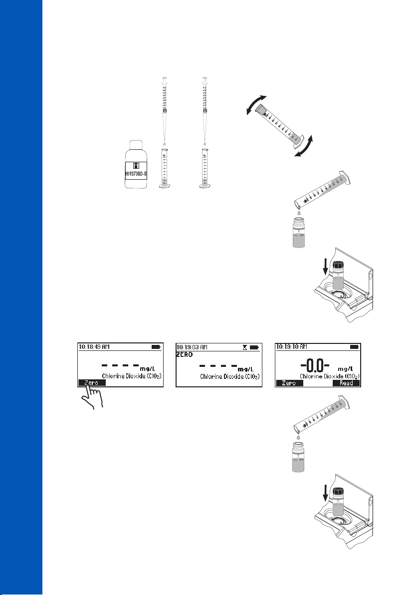
CHLORINE DIOXIDE
• Add 0.5 mL of HI93738D-0 Chlorine Dioxide Reagent to each cylinder (#1 & #2), using a 1 mL
syringe, cap them and invert several times to mix. Cylinder #2 is the reacted sample.
#1 & #2
METHOD PROCEDURES
• Fill cuvette (#1) with 10 mL of the blank (up to the mark).
Replace the plastic stopper and the cap.
• Insert the blank (#1) into the holder and close the lid.
• Press Zero. The display will show “-0.0-” when the meter is zeroed and ready for measurement.
• Fill second cuvette (#2) with 10 mL of the reacted sample
(up to the mark). Replace the plastic stopper and the cap.
#1
0.5 mL
#2
0.5 mL
#1
10 mL
#1
#2
10 mL
62
62
62
#2
• Insert the sample into the holder and close the lid.
Page 63

• Press Read to start the reading. The instrument displays the results in mg/L of chlorine dioxide
(ClO2).
INTERFERENCES
Interference may be caused by:
• Strong oxidants
METHOD PROCEDURES
CHLORINE DIOXIDE
63
63
63
Page 64

10.12. CHLORINE DIOXIDE, RAPID METHOD
SPECIFICATIONS
Range 0.00 to 2.00 mg/L (as ClO
Resolution 0.01 mg/L
Accuracy ±0.10 mg/L ±5% of reading at 25 °C
Light Source LED with narrow band interference filter @ 525 nm
Method Adaptation of Standard Methods for the Examination of Water and Wastewater,
18th Edition, 4500 ClO2 D
)
2
METHOD PROCEDURES
CHLORINE DIOXIDE, RAPID METHOD
REQUIRED REAGENT
Code Description Quantity
HI96779A-0 Chlorine Dioxide Reagent A 5 drops
HI96779B-0 Chlorine Dioxide Reagent B 1 packet
REAGENT SETS
HI96779-01 Reagents for 100 tests
HI96779-03 Reagents for 300 tests
For other accessories see ACCESSORIES section.
PRINCIPLE
The reaction between the Chlorine Dioxide and DPD indicator causes a pink tint in the sample, the
addition of glycine as a masking agent inhibits the response of free chlorine.
APPLICATION
Drinking water, tap water, treated water
SAMPLING PROCEDURE
Collect the sample in a clean glass bottle and analyze it immediately. Chlorine dioxide is a strong
oxidizing agent and is unstable in water.
SIGNIFICANCE & USE
Chlorine Dioxide is a commonly-used alternative to chlorine (Cl
Chlorophenol Red method (non-rapid method) reacts specifically with chlorine dioxide with little
interference from free chlorine or chloramines, but the method procedure is cumbersome. The Chlorine
Dioxide Rapid Method based on the DPD (N,N-diethyl-p-phenylenediamine) indicator is a much
simpler method by comparison, but it is susceptible to interference from other oxidizers. Glycine
(Reagent A) is able to convert free chlorine to chloroaminoacetic acid without affecting the analysis
of chlorine dioxide content.
64
64
64
) as a water disinfectant. The
2
Page 65
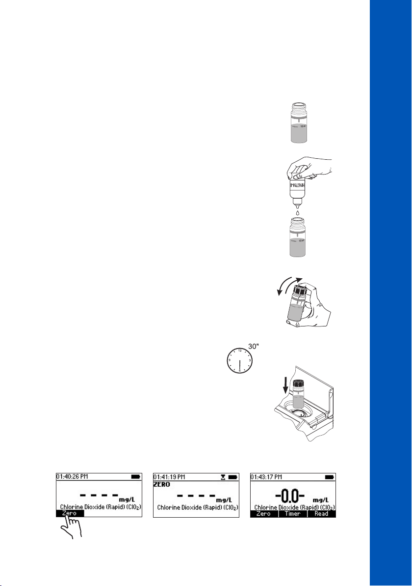
MEASUREMENT PROCEDURE
• Select the Chlorine Dioxide (Rapid) method using the procedure described in the METHOD
SELECTION section.
METHOD PROCEDURES
CHLORINE DIOXIDE, RAPID METHOD
• Fill the cuvette with 10 mL of unreacted sample (up to the mark).
• Add 5 drops of HI96779A-0 Chlorine Dioxide Reagent A.
• Replace the plastic stopper and the cap. Shake gently for
30 seconds.
• Wait for 30 seconds.
• Insert the cuvette into the holder and close the lid.
10 mL
×5
• Press Zero. The display will show “-0.0-” when the meter is zeroed and ready for measurement.
65
65
65
Page 66
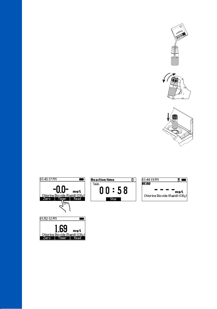
• Remove the cuvette.
• Add one packet of HI96779B-0 Chlorine Dioxide Reagent B.
METHOD PROCEDURES
• Replace the plastic stopper and the cap. Shake gently for 20 seconds.
• Insert the cuvette into the holder and close the lid.
CHLORINE DIOXIDE, RAPID METHOD
• Press Timer and the display will show the countdown prior to the measurement or wait 1 minute
and press Read. When the timer ends the meter will perform the reading. The instrument displays
the results in mg/L of ClO
.
2
66
66
66
Page 67

INTERFERENCES
Interference may be caused by:
• Acidity, Alkalinity, Flocculating agents, Hardness, Inorganic and Organic Chloramines, Manganese,
Metals, Monochloramine, Oxidized forms of Chromium and Manganese, Ozone and Peroxides
• Chlorine above 5 mg/L
• Bromine above 0.1 mg/L
• Highly buffered samples or extreme sample pH
METHOD PROCEDURES
CHLORINE DIOXIDE, RAPID METHOD
67
67
67
Page 68
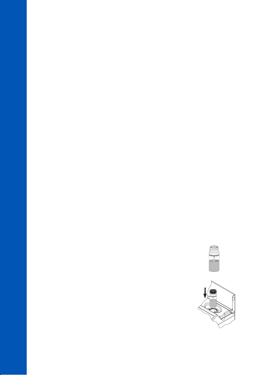
10.13. CHLORINE, FREE
SPECIFICATIONS
Range 0.00 to 5.00 mg/L (as Cl
Resolution 0.01 mg/L
Accuracy ±0.03 mg/L ±3% of reading at 25 °C
CHLORINE, FREE
METHOD PROCEDURES
Light Source LED with narrow band interference filter @ 525 nm
Method Adaptation of the EPA DPD Method 330.5
REQUIRED REAGENTS
POWDER
Code Description Quantity
HI93701-0 Free Chlorine Reagent 1 packet
LIQUID
Code Description Quantity
HI93701A-F Free Chlorine Reagent A 3 drops
HI93701B-F Free Chlorine Reagent B 3 drops
REAGENT SETS
HI93701-F Reagents for 300 tests (liquid)
HI93701-01 Reagents for 100 tests (powder)
HI93701-03 Reagents for 300 tests (powder)
For other accessories see ACCESSORIES section.
)
2
68
68
68
MEASUREMENT PROCEDURE
• Select the Chlorine (Free) method using the procedure described in the METHOD SELECTION section.
• Fill the cuvette with 10 mL of unreacted sample (up to the mark).
Replace the plastic stopper and the cap.
• Insert the cuvette into the holder and close the lid.
10 mL
Page 69
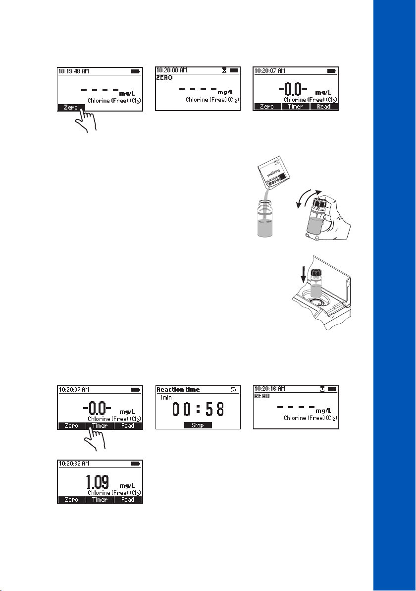
• Press Zero. The display will show “-0.0-” when the meter is zeroed and ready for measurement.
• Remove the cuvette.
POWDER REAGENT PROCEDURE
• Add the content of one packet of HI93701-0 Free
Chlorine Reagent. Replace the plastic stopper and the
cap. Shake gently for 20 seconds.
• Insert the cuvette into the holder and close the lid.
METHOD PROCEDURES
CHLORINE, FREE
• Press Timer and the display will show the countdown prior to the measurement or wait 1 minute
and press Read. When the timer ends the meter will perform the reading. The instrument displays
the results in mg/L of chlorine (Cl
).
2
69
69
69
Page 70
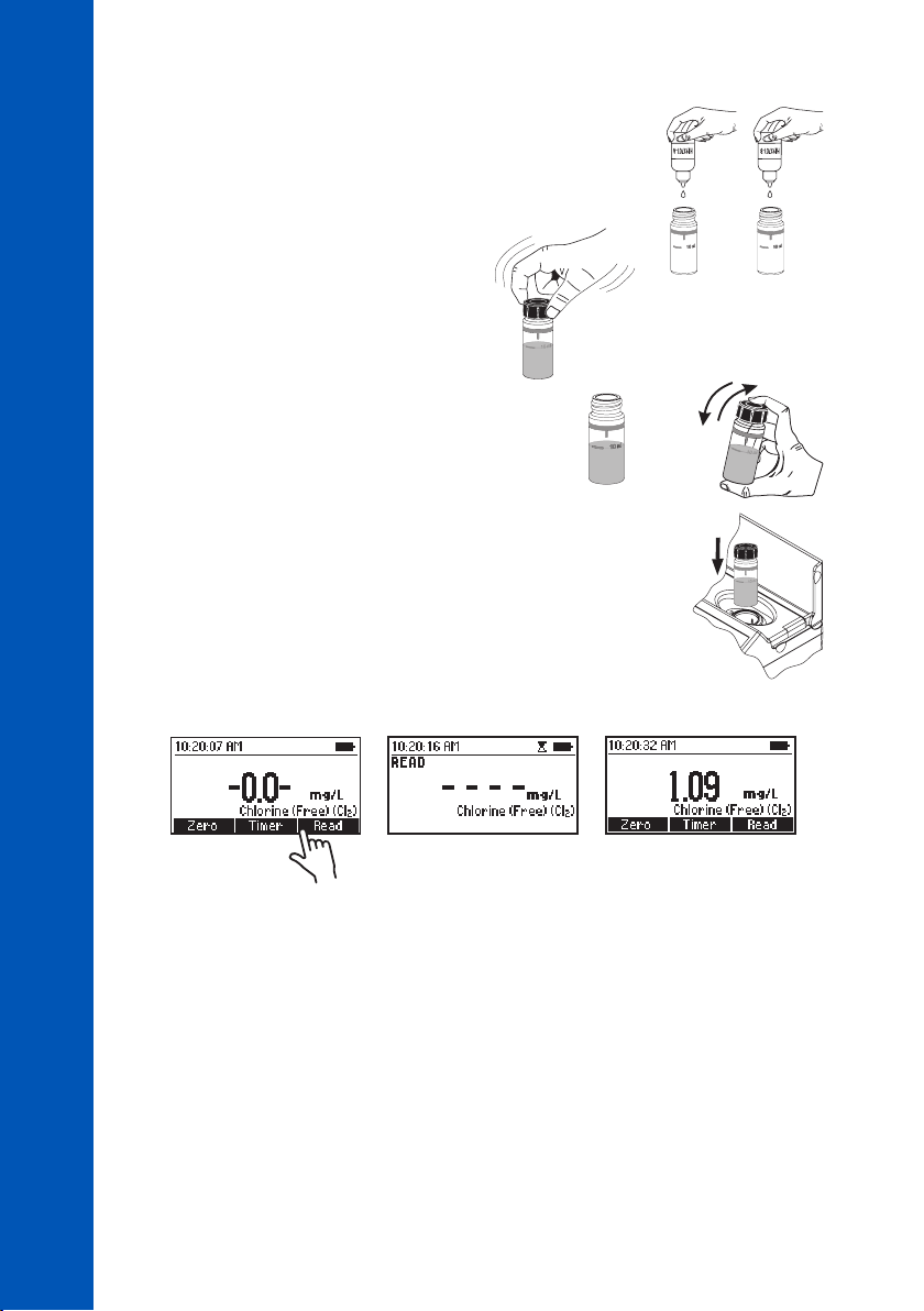
LIQUID REAGENT PROCEDURE
• To an empty cuvette add 3 drops of HI93701A-F Free Chlorine
Reagent A and 3 drops of HI93701B-F Free Chlorine Reagent B.
×3 ×3
CHLORINE, FREE
• Replace the plastic stopper and the cap.
Swirl gently to mix.
METHOD PROCEDURES
• Add 10 mL of unreacted sample (up to the mark). Replace
the plastic stopper and the cap. Shake gently.
• Insert the cuvette into the holder and close the lid.
• Press Read to start the reading. The instrument displays the results in mg/L of chlorine (Cl
Note: Free and Total Chlorine have to be measured separately with fresh sample following the
related procedure if both values are desired.
10 mL
).
2
70
70
70
INTERFERENCES
Interference may be caused by:
• Bromine, Iodine, Oxidized forms of Chromium and Manganese, Ozone
• Hardness greater than 500 mg/L CaCO
, to remove the interference shake the sample for
3
approximately 2 minutes after adding the powder reagent
• Alkalinity greater than 250 mg/L CaCO3 or acidity value greater than 150 mg/L CaCO3, the color
of the sample may develop only partially or rapidly fade, to remove the interference neutralize the
sample with diluted HCl or NaOH
Page 71
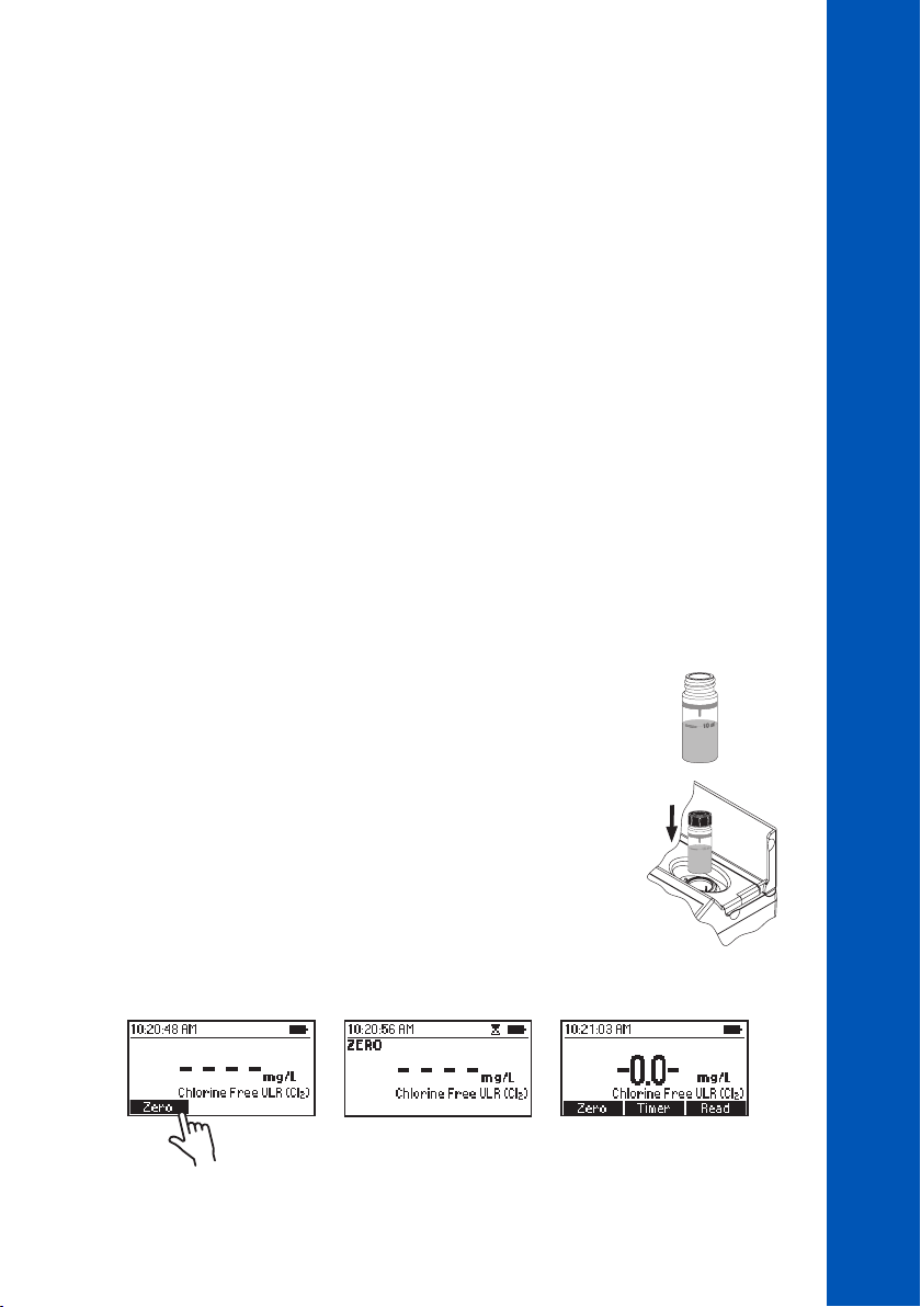
10.14. CHLORINE, FREE ULTRA LOW RANGE
SPECIFICATIONS
Range 0.000 to 0.500 mg/L (as Cl
Resolution 0.001 mg/L
Accuracy ±0.020 mg/L ±3% of reading at 25 °C
Light Source LED with narrow band interference filter @ 525 nm
Method Adaptation of the Standard Method 4500-Cl G
REQUIRED REAGENTS
Code Description Quantity
HI95762-0 Free Chlorine Ultra Low Range Reagent 1 packet
REAGENTS SETS
HI95762-01 Reagents for 100 tests
HI95762-03 Reagents for 300 tests
For other accessories see ACCESSORIES section.
MEASUREMENT PROCEDURE
• Select the Chlorine Free ULR method using the procedure described in the METHOD SELECTION
section.
)
2
METHOD PROCEDURES
CHLORINE, FREE ULTRA LOW RANGE
• Fill the cuvette with 10 mL of unreacted sample (up to the mark).
Replace the plastic stopper and the cap.
• Insert the cuvette into the holder and close the lid.
• Press Zero. The display will show “-0.0-” when the meter is zeroed and ready for measurement.
10 mL
71
71
71
Page 72

• Remove the cuvette.
• Add one packet of HI95762-0 Free Chlorine ULR
Reagent. Replace the plastic stopper and the cap. Shake
gently for 20 seconds.
METHOD PROCEDURES
CHLORINE, FREE ULTRA LOW RANGE
• Insert the cuvette into the holder and close the lid.
• Press Timer and the display will show the countdown prior to the measurement or wait 1 minute
and press Read. When the timer ends the meter will perform the reading. The instrument displays
the results in mg/L of chlorine (Cl
INTERFERENCES
Interference may be caused by:
• Bromine, Chlorine Dioxide, Iodine, Oxidized forms of Chromium and Manganese, Ozone
• Alkalinity greater than 1000 mg/L CaCO3 if present as bicarbonate (pH < 8.3), above 25 mg/L
CaCO3 if present as carbonate (pH > 9.0) or acidity value greater than 150 mg/L CaCO3, the color
of the sample may develop only partially or rapidly fade, to remove the interference neutralize the
sample with diluted HCl or NaOH
• Hardness greater than 500 mg/L CaCO3, to remove the interference shake the sample for
approximately 2 minutes after adding the powder reagent
).
2
72
72
72
Page 73
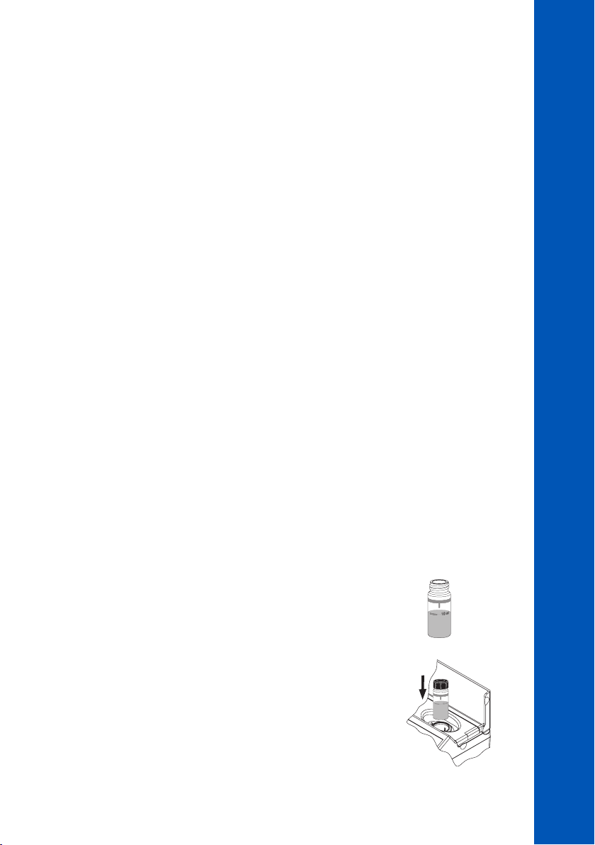
10.15. CHLORINE, TOTAL
SPECIFICATIONS
Range 0.00 to 5.00 mg/L (as Cl
Resolution 0.01 mg/L
Accuracy ±0.03 mg/L ±3% of reading at 25 °C
Light Source LED with narrow band interference filter @ 525 nm
Method Adaptation of the EPA DPD Method 330.5
REQUIRED REAGENTS
POWDER
Code Description Quantity
HI93711-0 Total Chlorine Reagent 1 packet
LIQUID
Code Description Quantity
HI93701A-T Total Chlorine Reagent A 3 drops
HI93701B-T Total Chlorine Reagent B 3 drops
HI93701C-T Total Chlorine Reagent C 1 drop
REAGENT SETS
HI93701-T Reagents for 300 tests (liquid)
HI93711-01 Reagents for 100 total tests (powder)
HI93711-03 Reagents for 300 total tests (powder)
For other accessories see ACCESSORIES section.
)
2
METHOD PROCEDURES
CHLORINE, TOTAL
MEASUREMENT PROCEDURE
• Select the Chlorine (Total) method using the procedure described in the METHOD SELECTION
section.
• Fill the cuvette with 10 mL of unreacted sample (up to the mark).
Replace the plastic stopper and the cap.
• Insert the cuvette into the holder and close the lid.
10 mL
73
73
73
Page 74
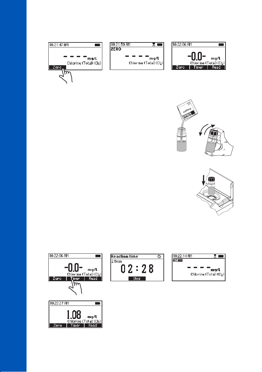
• Press Zero. The display will show “-0.0-” when the meter is zeroed and ready for measurement.
CHLORINE, TOTAL
• Remove the cuvette.
METHOD PROCEDURES
POWDER REAGENT PROCEDURE
• Add 1 packet of HI93711-0 Total Chlorine Reagent.
Replace the plastic stopper and the cap. Shake gently
for 20 seconds.
• Insert the cuvette into the holder and close the lid.
74
74
74
• Press Timer and the display will show the countdown prior to the measurement or wait 2 minutes
and 30 seconds and press Read. When the timer ends the meter will perform the reading. The
instrument displays the results in mg/L of chlorine (Cl
).
2
Page 75
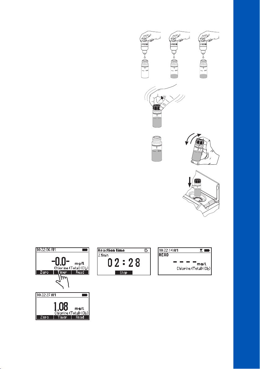
LIQUID REAGENT PROCEDURE
METHOD PROCEDURES
CHLORINE, TOTAL
• To an empty cuvette add 3 drops of HI93701A-T
Total Chlorine Reagent A, 3 drops of HI93701B-T
Total Chlorine Reagent B and 1 drop of HI93701C-T
Total Chlorine Reagent C.
• Replace the plastic stopper and the cap. Swirl gently
to mix.
• Add 10 mL of unreacted sample (up to the mark).
Replace the plastic stopper and the cap. Shake
gently.
• Insert the cuvette into the holder and close the lid.
• Press Timer and the display will show the countdown prior to the measurement or wait 2 minutes
and 30 seconds and press Read. When the timer ends the meter will perform the reading. The
instrument displays the results in mg/L of chlorine (Cl
×3 ×3 ×1
10 mL
).
2
Note: Free and Total Chlorine have to be measured separately with fresh unreacted samples
following the related procedure if both values are desired.
75
75
75
Page 76

INTERFERENCES
Interference may be caused by:
• Bromine, Iodine, Oxidized forms of Chromium and Manganese, Ozone
• Hardness greater than 500 mg/L CaCO3, to remove the interference shake the sample for
approximately 2 minutes after adding the powder reagent
• Alkalinity greater than 250 mg/L CaCO3 or acidity greater than 150 mg/L CaCO3, the color of the
sample may develop only partially or may rapidly fade, to remove the interference neutralize the
CHLORINE, TOTAL
sample with diluted HCl or NaOH
METHOD PROCEDURES
76
76
76
Page 77
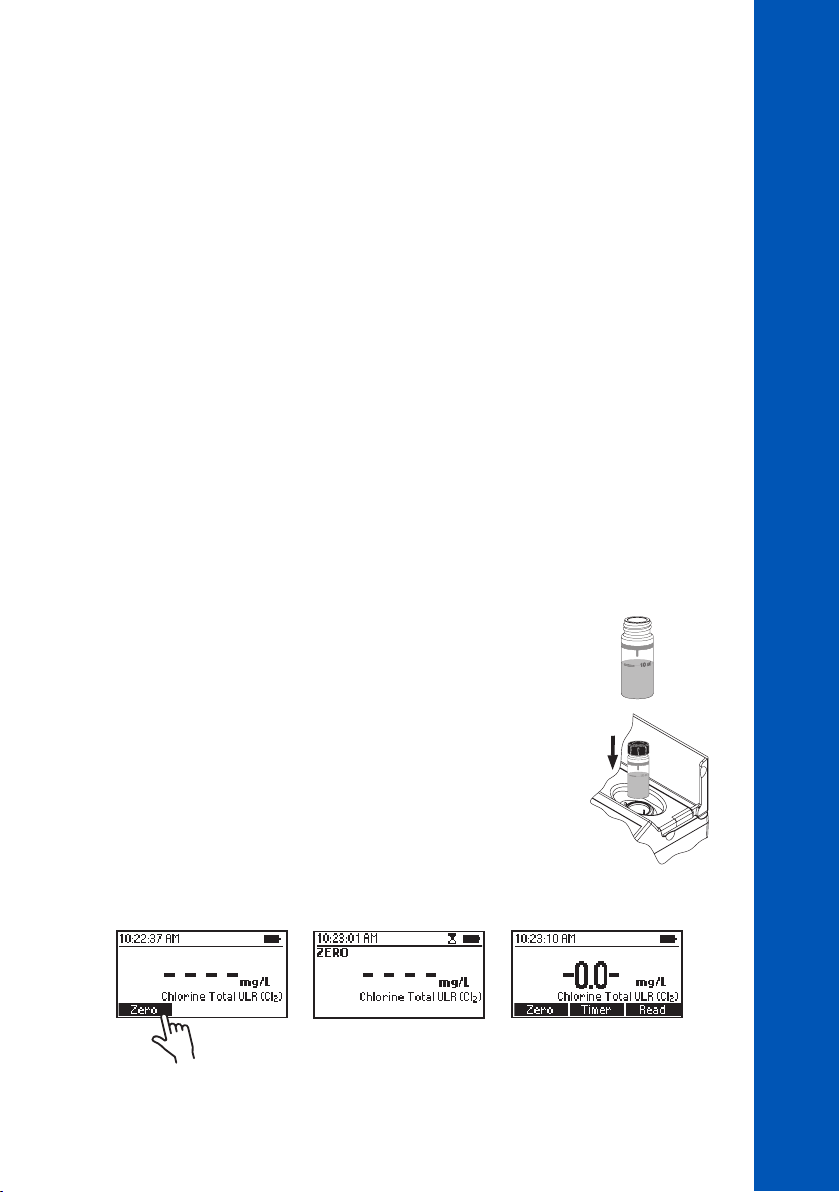
10.16. CHLORINE, TOTAL ULTRA LOW RANGE
SPECIFICATIONS
Range 0.000 to 0.500 mg/L (as Cl
Resolution 0.001 mg/L
Accuracy ±0.020 mg/L ±3% of reading at 25 °C
Light Source LED with narrow band interference filter @ 525 nm
Method Adaptation of the EPA Method 330.5
REQUIRED REAGENTS
Code Description Quantity
HI95761-0 Total Chlorine Ultra Low Range Reagent 1 packet
REAGENT SETS
HI95761-01 Reagents for 100 tests
HI95761-03 Reagents for 300 tests
For other accessories see ACCESSORIES section.
MEASUREMENT PROCEDURE
• Select the Chlorine (Total) ULR method using the procedure described in the METHOD SELECTION
section.
)
2
METHOD PROCEDURES
CHLORINE, TOTAL ULTRA LOW RANGE
• Fill the cuvette with 10 mL of unreacted sample (up to the mark).
Replace the plastic stopper and the cap.
• Insert the cuvette into the holder and close the lid.
• Press Zero. The display will show “-0.0-” when the meter is zeroed and ready for measurement.
10 mL
77
77
77
Page 78
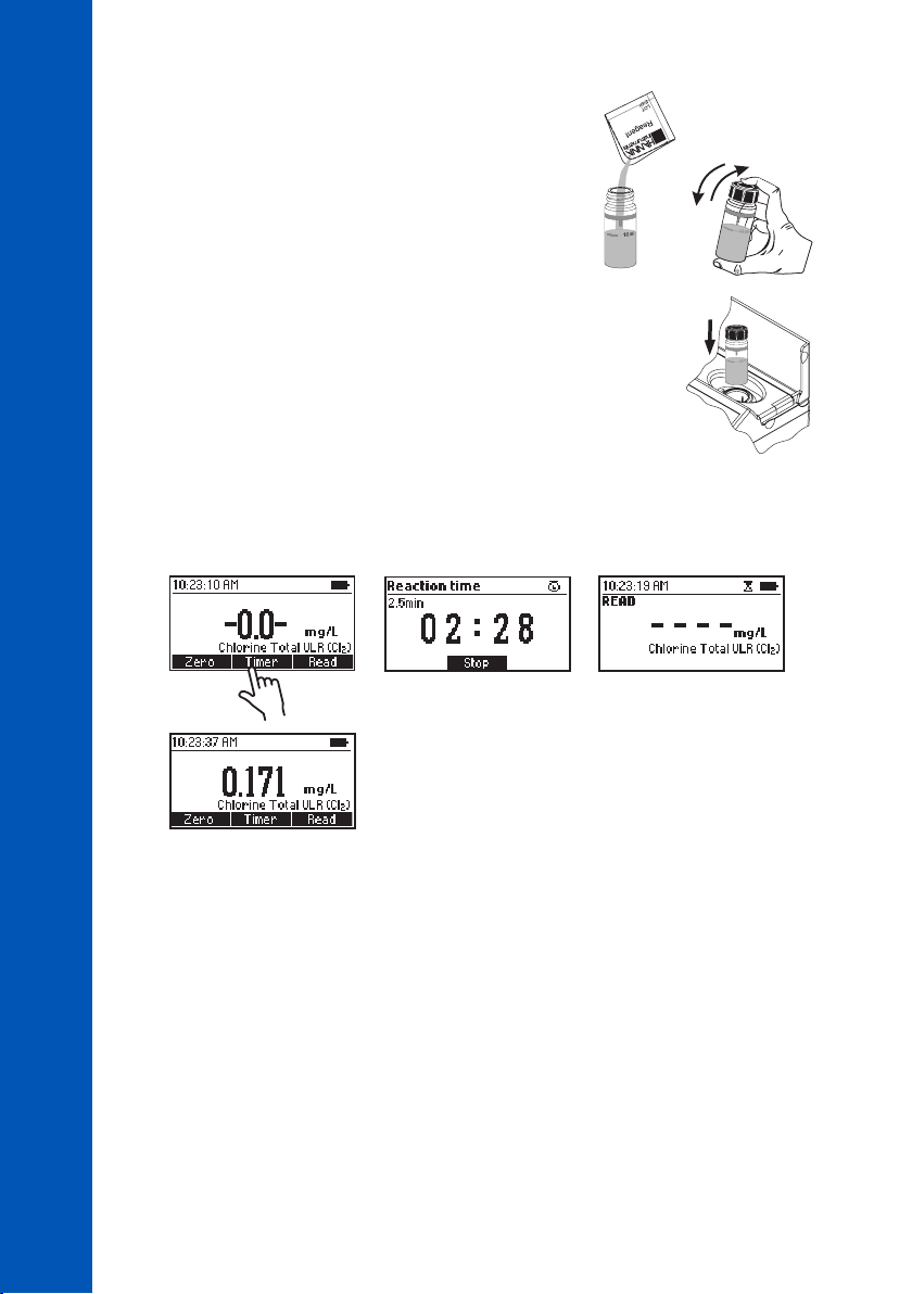
• Remove the cuvette.
• Add one packet of HI95761-0 Total Chlorine ULR
Reagent. Replace the plastic stopper and the cap. Shake
gently for 20 seconds.
METHOD PROCEDURES
• Insert the cuvette into the holder and close the lid.
• Press Timer and the display will show the countdown prior to the measurement or wait 2 minutes
and 30 seconds and press Read. When the timer ends the meter will perform the reading. The
CHLORINE, TOTAL ULTRA LOW RANGE
instrument displays the results in mg/L of chlorine (Cl
INTERFERENCES
Interference may be caused by:
• Bromine, Chlorine Dioxide, Iodine, Oxidized forms of Chromium and Manganese, Ozone
• Alkalinity greater than 1000 mg/L CaCO3 if present as bicarbonate (pH < 8.3), above 25 mg/L
if present as carbonate (pH > 9.0) or acidity value greater than 150 mg/L CaCO3, the color
CaCO
3
of the sample may develop only partially or rapidly fade, to remove the interference neutralize the
sample with diluted HCl or NaOH
• Hardness greater than 500 mg/L CaCO
approximately 2 minutes after adding the powder reagent
).
2
, to remove the interference shake the sample for
3
78
78
78
Page 79
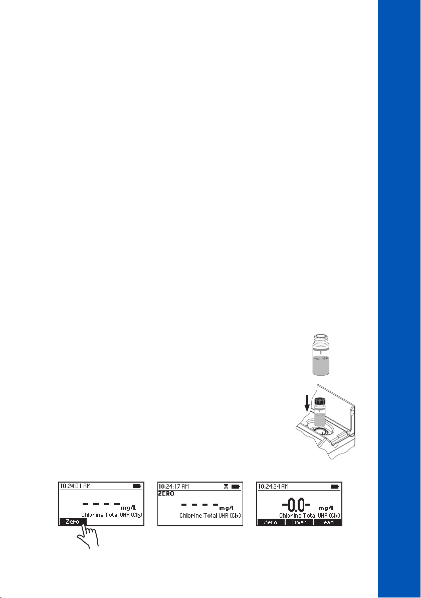
10.17. CHLORINE, TOTAL ULTRA HIGH RANGE
SPECIFICATIONS
Range 0 to 500 mg/L (as Cl
Resolution 1 mg/L
Accuracy ±3 mg/L ±3% of reading at 25 °C
Light Source LED lamp with narrow band interference filter @ 525 nm
Method Adaptation of Standard Methods for Examination of Water and
Wastewater, 20th Edition, 4500-Cl
REQUIRED REAGENTS
Code Description Quantity
HI95771A-0 Total Chlorine Ultra High Range Reagent A 1 packet
HI95771B-0 Total Chlorine Ultra High Range Reagent B 1 packet
REAGENTS SETS
HI95771-01 Reagents for 100 tests
HI95771-03 Reagents for 300 tests
For other accessories see ACCESSORIES section.
MEASUREMENT PROCEDURE
• Select the Chlorine (Total) UHR method using the procedure described in the METHOD SELECTION
section.
)
2
METHOD PROCEDURES
CHLORINE, TOTAL ULTRA HIGH RANGE
• Fill the cuvette with 10 mL of unreacted sample (up to the mark).
Replace the plastic stopper and the cap.
• Insert the cuvette into the holder and close the lid.
• Press Zero. The display will show “-0.0-” when the meter is zeroed and ready for measurement.
10 mL
79
79
79
Page 80
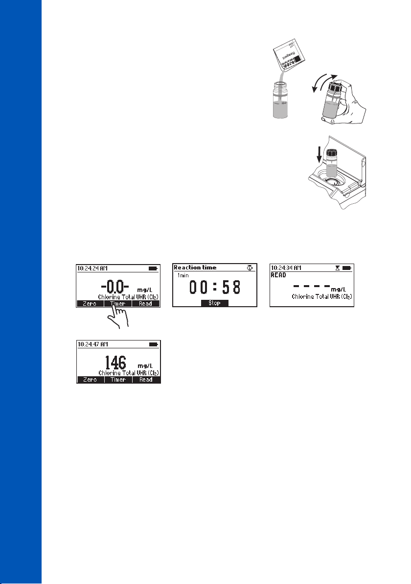
• Remove the cuvette.
• Add one packet of HI95771A-0 Total Chlorine Ultra High
Range Reagent A and one packet HI95771B-0 Total
Chlorine Ultra High Range Reagent B. Replace the plastic
stopper and the cap. Shake gently for 20 seconds.
METHOD PROCEDURES
CHLORINE, TOTAL ULTRA HIGH RANGE
• Insert the cuvette into the holder and close the lid.
• Press Timer and the display will show the countdown prior to the measurement or wait 1 minute
and press Read. When the timer ends the meter will perform the reading. The instrument displays
the results in mg/L of chlorine (Cl
INTERFERENCES
Interference may be caused by:
• Bromine, Chlorine Dioxide, Chromium, Iodine, Oxidized Manganese, Ozone
).
2
80
80
80
Page 81
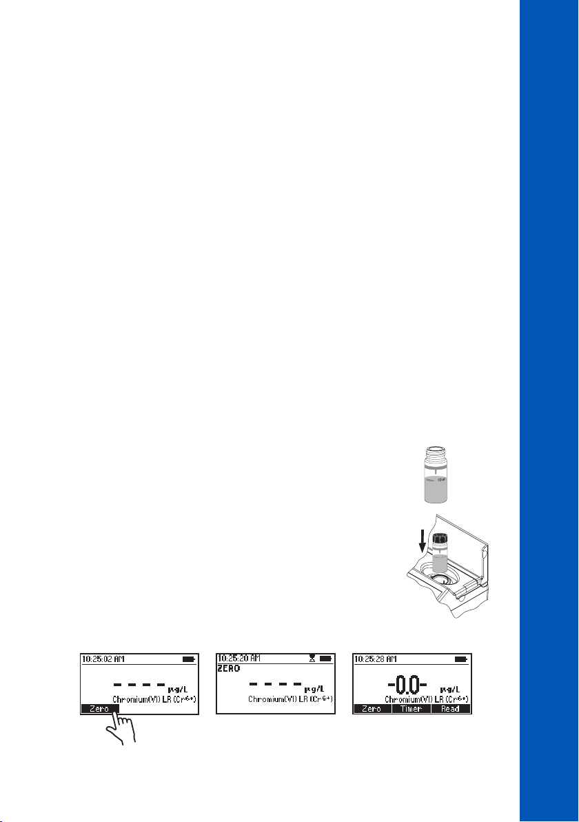
10.18. CHROMIUM(VI) LOW RANGE
METHOD PROCEDURES
CHROMIUM(VI) LOW RANGE
SPECIFICATIONS
Range 0 to 300 µg/L (as Cr
Resolution 1 µg/L
Accuracy ±10 µg/L ±4% of reading at 25 °C
Light Source LED with narrow band interference filter @ 525 nm
Method Adaptation of the ASTM Manual of Water and Environmental Technology,
D1687 Diphenylcarbohydrazide Method
REQUIRED REAGENTS
Code Description Quantity
HI93749-0 Chromium(VI) Low Range Reagent 1 packet
REAGENT SETS
HI93749-01 Reagents for 100 tests
HI93749-03 Reagents for 300 tests
For other accessories see ACCESSORIES section.
MEASUREMENT PROCEDURE
• Select the Chromium(VI) LR method using the procedure described in the METHOD SELECTION
section.
• Fill the cuvette with 10 mL of unreacted sample (up to the mark).
Replace the plastic stopper and the cap.
(VI))
10 mL
• Insert the cuvette into the holder and close the lid.
• Press Zero. The display will show “-0.0-” when the meter is zeroed and ready for measurement.
81
81
81
Page 82
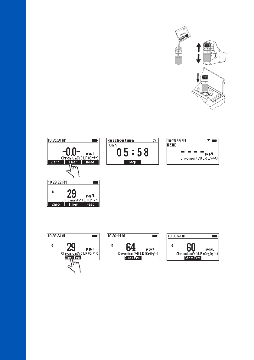
• Remove the cuvette.
• Add one packet of HI93749-0 Chromium(VI) Low Range Reagent.
Replace the plastic stopper and the cap. Shake vigorously for
about 10 seconds.
• Insert the cuvette into the holder and close the lid.
METHOD PROCEDURES
• Press Timer and the display will show the countdown prior to the measurement or wait 6 minutes
CHROMIUM(VI) LOW RANGE
and press Read. When the timer ends the meter will perform the reading. The instrument displays
concentration in µg/L of chromium (Cr
6+
).
82
82
82
• Press the or key to access the second level functions.
2
• Press Chem Frm to convert the result to µg/L of chromate (CrO
¯) and dichromate (Cr2O
4
• Press the or key to return to the measurement screen.
INTERFERENCES
Interference may be caused by:
• Vanadium above 1 mg/L, wait 10 minutes before reading to remove the interference
• Iron above 1 mg/L
• Mercurous and mercuric ions slight inhibition of the reaction
2
¯).
7
Page 83
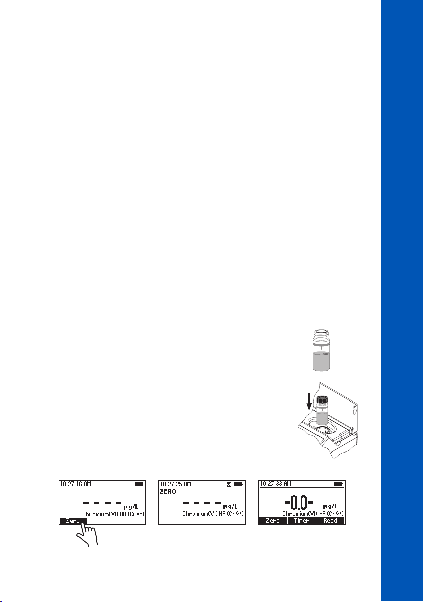
10.19. CHROMIUM(VI) HIGH RANGE
SPECIFICATIONS
Range 0 to 1000 µg/L (as Cr(VI))
Resolution 1 µg/L
Accuracy ±5 µg/L ±4% of reading at 25 °C
Light Source LED with narrow band interference filter @ 525 nm
Method Adaptation of the ASTM Manual of Water and Environmental Technology,
D1687-92, Diphenylcarbohydrazide Method
REQUIRED REAGENTS
Code Description Quantity
HI93723-0 Chromium(VI) High Range Reagent 1 packet
REAGENT SETS
HI93723-01 Reagents for 100 tests
HI93723-03 Reagents for 300 tests
For other accessories see ACCESSORIES section.
MEASUREMENT PROCEDURE
• Select the Chromium(VI) HR method using the procedure described in the METHOD SELECTION
section.
METHOD PROCEDURES
CHROMIUM(VI) HIGH RANGE
• Fill the cuvette with 10 mL of unreacted sample (up to the mark).
Replace the plastic stopper and the cap.
• Insert the cuvette into the holder and close the lid.
• Press Zero. The display will show “-0.0-” when the meter is zeroed and ready for measurement.
10 mL
83
83
83
Page 84
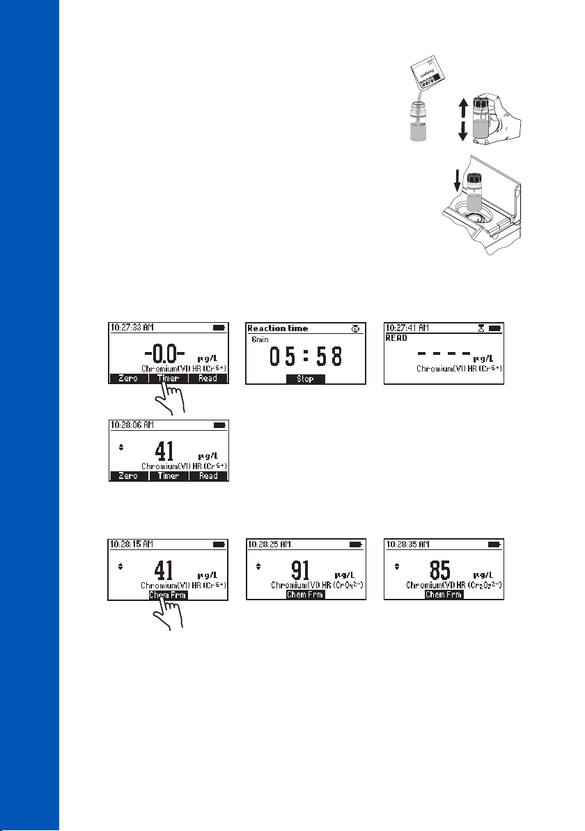
• Remove the cuvette.
• Add one packet of HI93723-0 Chromium(VI) High Range Reagent.
Replace the plastic stopper and the cap. Shake vigorously for
about 10 seconds.
• Insert the cuvette into the holder and close the lid.
METHOD PROCEDURES
• Press Timer and the display will show the countdown prior to the measurement or wait 6 minutes
CHROMIUM(VI) HIGH RANGE
and press Read. When the timer ends the meter will perform the reading. The instrument displays
concentration in µg/L of chromium (Cr
6+
).
84
84
84
• Press the or key to access the second level functions.
• Press Chem Frm to convert the result to µg/L of chromate (CrO
2¯
) and dichromate (Cr2O
4
• Press the or key to return to the measurement screen.
INTERFERENCES
Interference may be caused by:
• Vanadium above 1 mg/L, wait 10 minutes before reading to remove the interference
• Iron above 1 mg/L
• Mercurous and mercuric ions slight inhibition of the reaction
2¯
).
7
Page 85
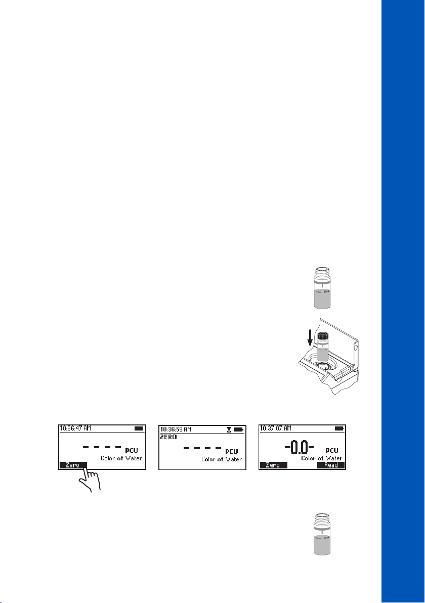
10.20. COLOR OF WATER
SPECIFICATIONS
Range 0 to 500 PCU (Platinum Cobalt Units)
Resolution 1 PCU
Accuracy ±10 PCU ±5% of reading at 25 °C
Light Source LED with narrow band interference filter @ 420 nm
Method Adaptation of Standard Methods for the Examination of Water and
Wastewater, 18
REQUIRED ACCESSORIES
0.45 µm membrane for true color measurement
For other accessories see ACCESSORIES section.
MEASUREMENT PROCEDURE
• Select the Color of Water method using the procedure described in the METHOD SELECTION section.
th
Edition, Colorimetric Platinum Cobalt Method
METHOD PROCEDURES
COLOR OF WATER
• Fill the first cuvette (#1) with 10 mL of deionized water (up to
the mark). Replace the plastic stopper and the cap. This is the
blank.
#1
• Insert the blank (#1) into the holder and close the lid.
• Press Zero. The display will show “-0.0-” when the meter is zeroed and ready for measurement.
• Remove the cuvette
• Fill the second cuvette (#2) with 10 mL of unfiltered
sample (up to the mark). Replace the plastic stopper and
the cap. This is the apparent color.
10 mL
#1
10 mL
#2
85
85
85
Page 86
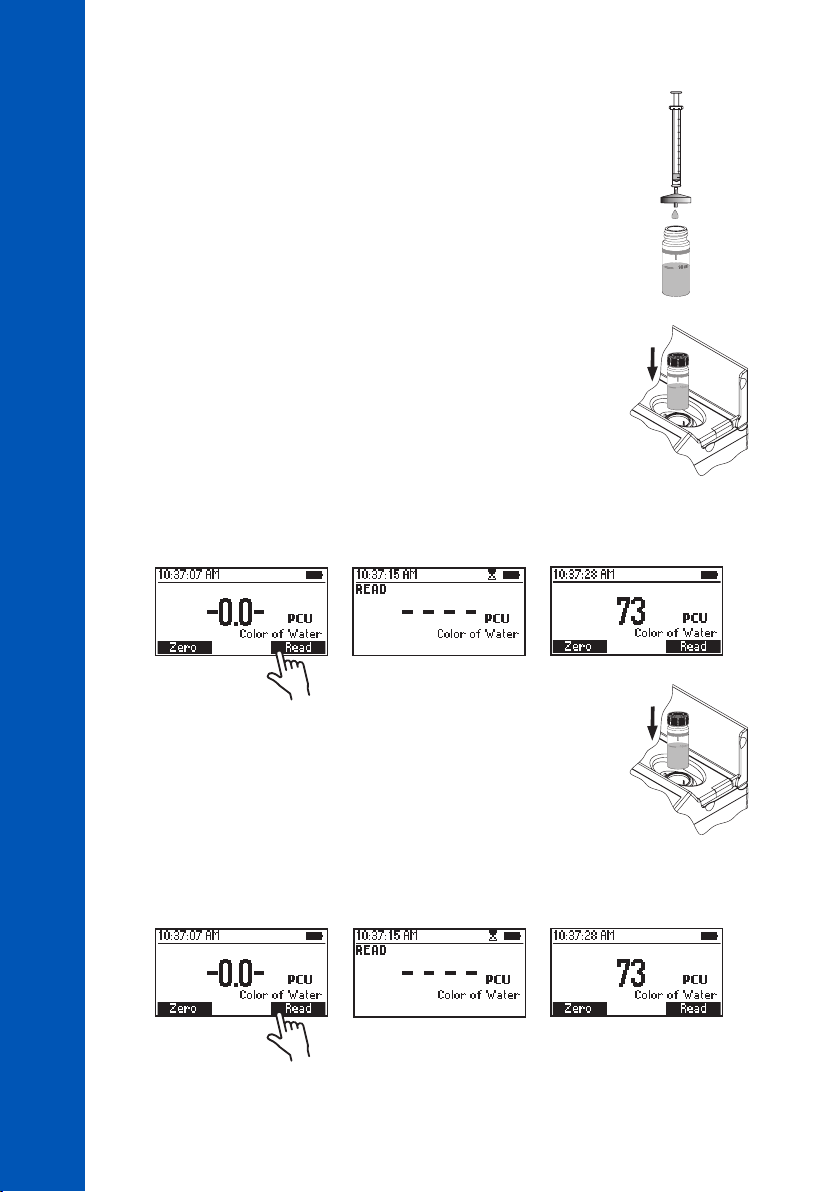
• Filter 10 mL of sample through a filter with a 0.45 µm
membrane into the third cuvette (#3), up to the 10 mL
mark. Replace the plastic stopper and the cap. This is
the true color.
COLOR OF WATER
METHOD PROCEDURES
• Insert the apparent color cuvette (#2) into the holder
and close the lid.
• Press Read to start the reading. The meter displays the value of apparent color in Platinum Cobalt
Units (PCU).
#3
#2
86
86
86
• Remove the apparent color cuvette (#2) from the
#3
holder, insert the true color cuvette (#3) into the holder
and close the lid.
• Press Read to start the reading. The meter displays the true color in Platinum Cobalt Units
(PCU).
Page 87
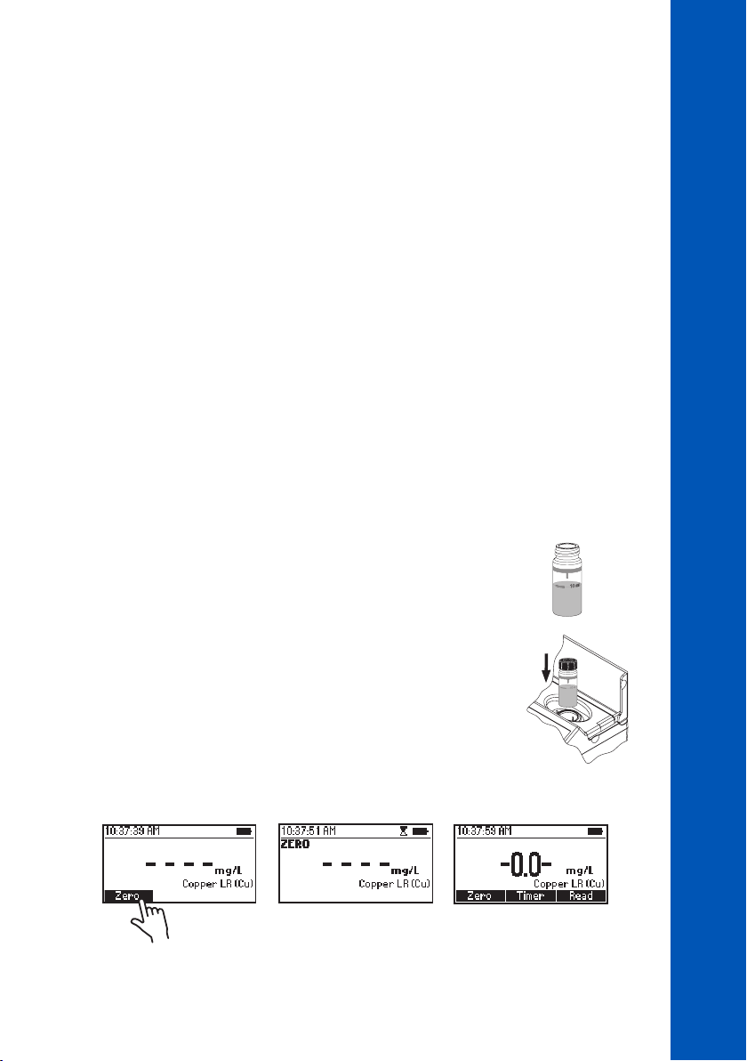
10.21. COPPER LOW RANGE
METHOD PROCEDURES
COPPER LOW RANGE
SPECIFICATIONS
Range 0.000 to 1.500 mg/L (as Cu
Resolution 0.001 mg/L
Accuracy ±0.010 mg/L ±5% of reading at 25 °C
Light Source LED with narrow band interference filter @ 575 nm
Method Adaptation of the EPA Method
REQUIRED REAGENTS
Code Description Quantity
HI95747-0 Copper Low Range Reagent 1 packet
REAGENT SETS
HI95747-01 Reagents for 100 tests
HI95747-03 Reagents for 300 tests
For other accessories see ACCESSORIES section.
MEASUREMENT PROCEDURE
• Select the Copper LR method using the procedure described in the METHOD SELECTION section.
• Fill the cuvette with 10 mL of unreacted sample (up to the mark).
Replace the plastic stopper and the cap.
2+
)
10 mL
• Insert the cuvette into the holder and close the lid.
• Press Zero. The display will show “-0.0-” when the meter is zeroed and ready for measurement.
87
87
87
Page 88
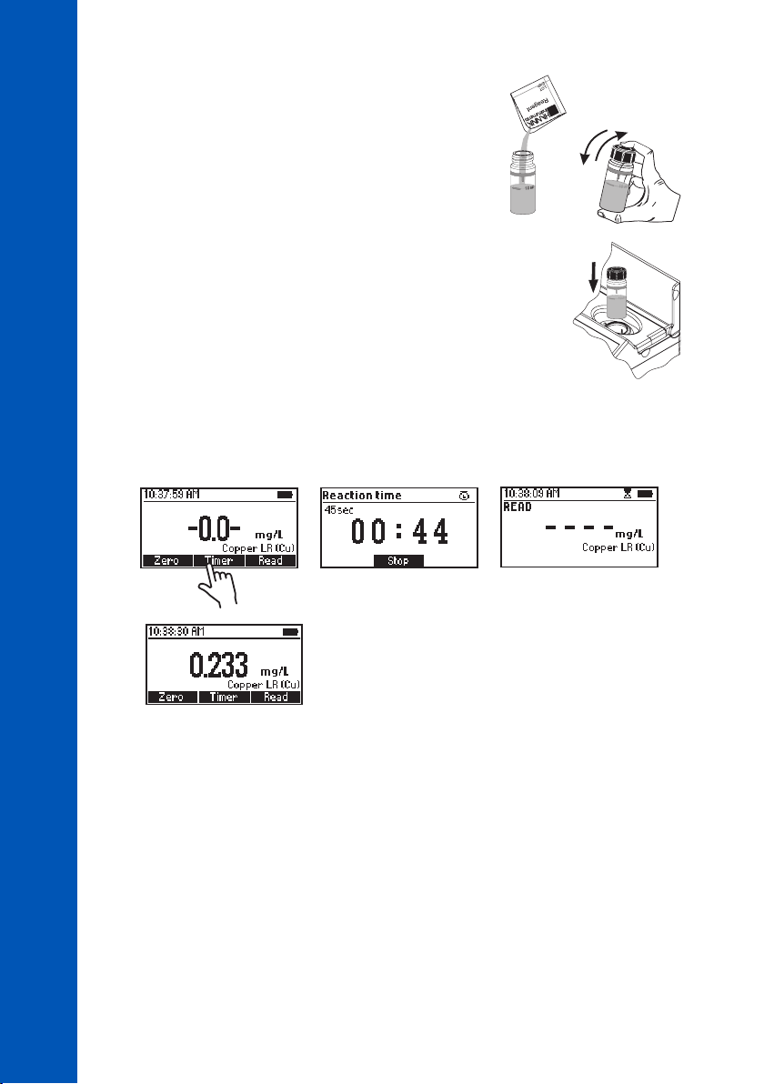
• Remove the cuvette.
• Add one packet of HI95747-0 Copper Low Range
Reagent. Replace the plastic stopper and the cap. Shake
gently for about 15 seconds.
COPPER LOW RANGE
METHOD PROCEDURES
• Insert the cuvette into the holder and close the lid.
• Press Timer and the display will show the countdown prior to the measurement or wait 45 seconds
and press Read. When the timer ends the meter will perform the reading. The instrument displays
the results in mg/L of copper (Cu).
INTERFERENCES
Interference may be caused by:
• Cyanide, Silver
• For samples overcoming buffering capacity of reagent around pH 6.8, pH should be adjusted
between 6 and 8
88
88
88
Page 89
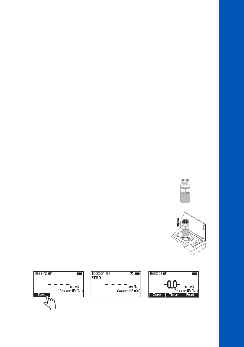
10.22. COPPER HIGH RANGE
METHOD PROCEDURES
COPPER HIGH RANGE
SPECIFICATIONS
Range 0.00 to 5.00 mg/L (as Cu
Resolution 0.01 mg/L
Accuracy ±0.02 mg/L ±4% of reading at 25 °C
Light Source LED with narrow band interference filter @ 575 nm
Method Adaptation of the EPA Method
REQUIRED REAGENTS
Code Description Quantity
HI93702-0 Copper High Range Reagent 1 packet
REAGENT SETS
HI93702-01 Reagents for 100 tests
HI93702-03 Reagents for 300 tests
For other accessories see ACCESSORIES section.
MEASUREMENT PROCEDURE
• Select the Copper HR method using the procedure described in the METHOD SELECTION section.
• Fill the cuvette with 10 mL of unreacted sample (up to the mark).
Replace the plastic stopper and the cap.
2+
)
10 mL
• Insert the cuvette into the holder and close the lid.
• Press Zero. The display will show “-0.0-” when the meter is zeroed and ready for measurement.
89
89
89
Page 90
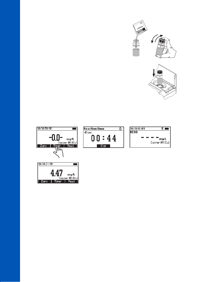
• Remove the cuvette.
• Add one packet of HI93702-0 Copper High Range Reagent.
Replace the plastic stopper and the cap. Shake gently for
about 15 seconds.
COPPER HIGH RANGE
METHOD PROCEDURES
• Insert the cuvette into the holder and close the lid.
• Press Timer and the display will show the countdown prior to the measurement or wait 45 seconds
and press Read. When the timer ends the meter will perform the reading. The instrument displays
the results in mg/L of copper (Cu).
INTERFERENCES
Interference may be caused by:
• Cyanide, Silver
• For samples overcoming buffering capacity of reagent around pH 6.8, pH should be adjusted
between 6 and 8
90
90
90
Page 91
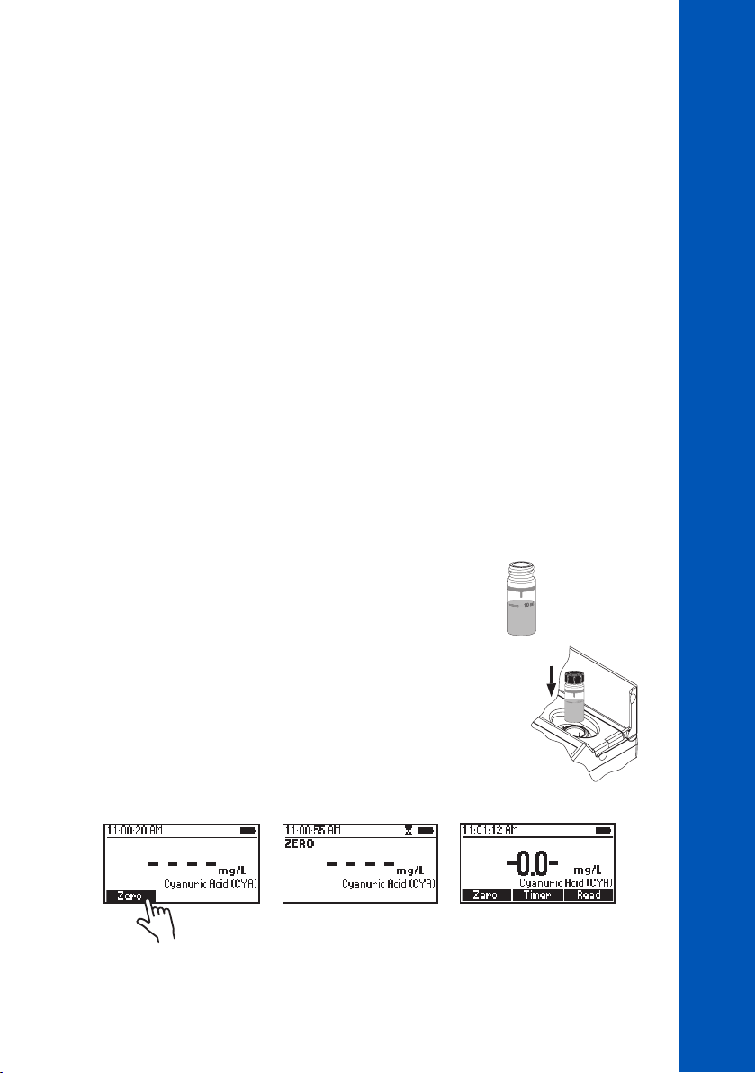
10.23. CYANURIC ACID
SPECIFICATIONS
Range 0 to 80 mg/L (as CYA)
Resolution 1 mg/L
Accuracy ±1 mg/L ±15% of reading at 25 °C
Light Source LED with narrow band interference filter @ 525 nm
Method Adaptation of the Turbidimetric Method
REQUIRED REAGENTS
Code Description Quantity
HI93722-0 Cyanuric Acid Reagent 1 packet
REAGENT SETS
HI93722-01 Reagents for 100 tests
HI93722-03 Reagents for 300 tests
For other accessories see ACCESSORIES section.
MEASUREMENT PROCEDURE
• Select the Cyanuric Acid method using the procedure described in the METHOD SELECTION section.
METHOD PROCEDURES
CYANURIC ACID
• Fill the first cuvette with 10 mL of unreacted sample (up to
the mark). Replace the plastic stopper and the cap.
• Insert the cuvette into the holder and close the lid.
• Press Zero. The display will show “-0.0-” when the meter is zeroed and ready for measurement.
10 mL
# 1
# 1
91
91
91
Page 92
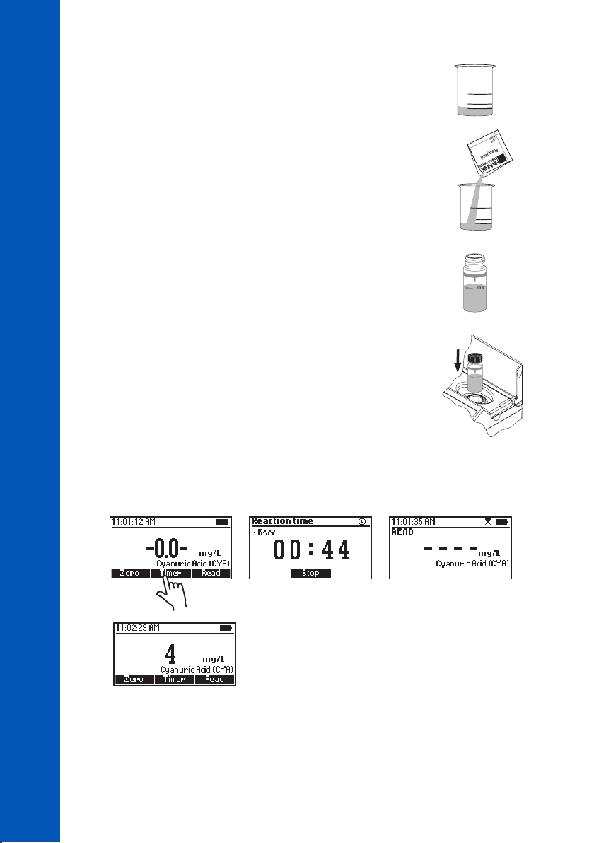
• Fill a beaker with 25 mL sample.
CYANURIC ACID
• Add one packet of HI93722-0 Cyanuric Acid Reagent and
mix to dissolve.
METHOD PROCEDURES
• Fill a second cuvette with 10 mL of the reacted sample (up to
the mark). Replace the plastic stopper and the cap.
• Insert the cuvette into the holder and close the lid.
• Press Timer and the display will show the countdown prior to the measurement or wait 45 seconds
and press Read. When the timer ends the meter will perform the reading. The instrument displays
the concentration in mg/L of cyanuric acid.
# 2
10 mL
# 2
92
92
92
Page 93
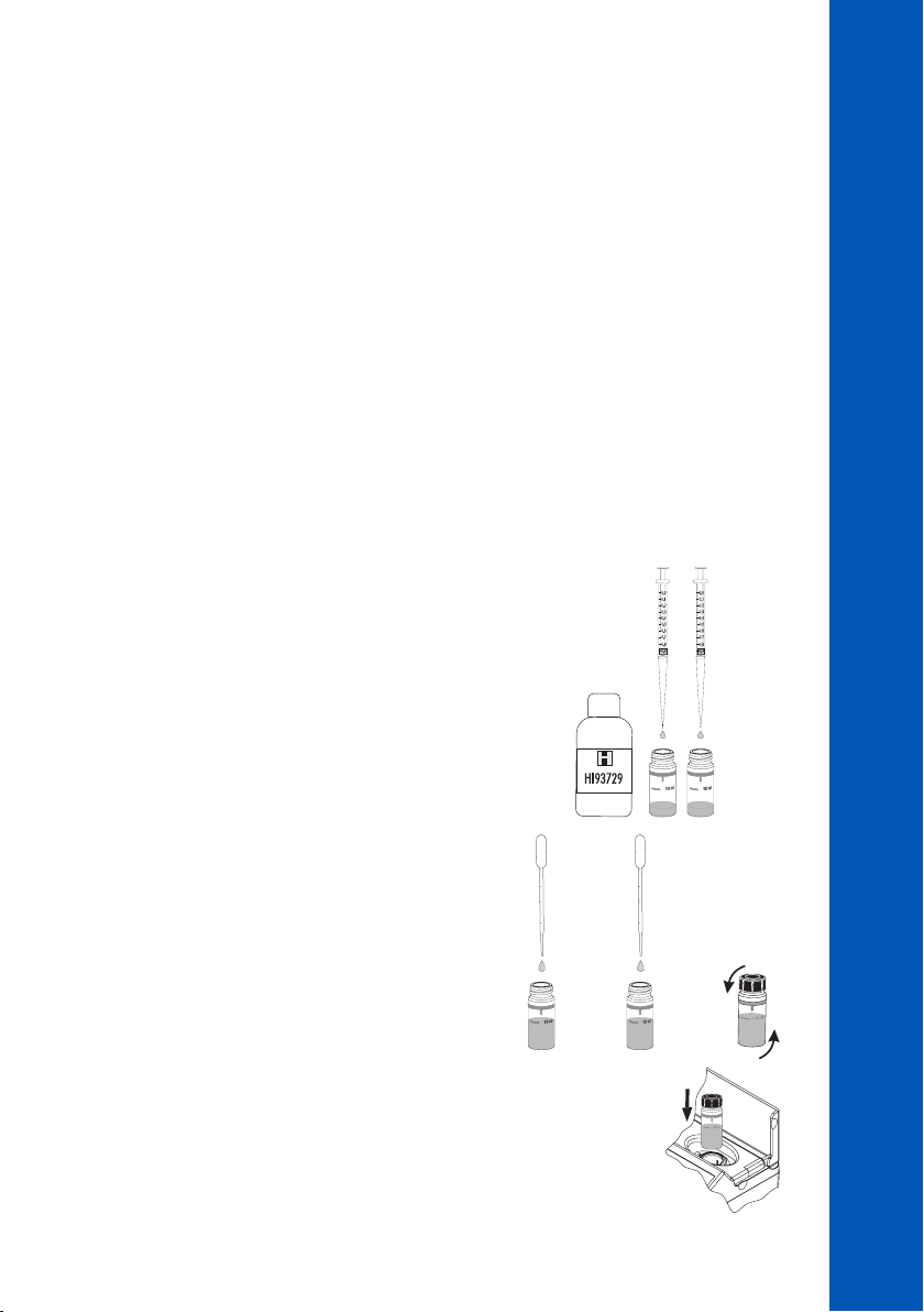
10.24. FLUORIDE LOW RANGE
METHOD PROCEDURES
FLUORIDE LOW RANGE
SPECIFICATIONS
Range 0.00 to 2.00 mg/L (as F
Resolution 0.01 mg/L
Accuracy ±0.03 mg/L ±3% of reading at 25 °C
Light Source LED with narrow band interference filter @ 575 nm
Method Adaptation of Standard Methods for the Examination of Water and
Wastewater, 18th Edition, SPADNS Method
REQUIRED REAGENT
Code Description Quantity
HI93729-0 Fluoride Low Range Reagent 4 mL
REAGENT SETS
HI93729-01 Reagents for 100 tests
HI93729-03 Reagents for 300 tests
For other accessories see ACCESSORIES section.
MEASUREMENT PROCEDURE
• Select the Fluoride LR method using the procedure
described in the METHOD SELECTION section.
• Add 2 mL of HI93729-0 Fluoride Low Range Reagent
to two cuvettes.
-
)
2 mL
• Use a plastic pipette to fill one cuvette with 10 mL of
deionized water (up to the mark) (#1). Replace the
plastic stopper and the cap. Invert several times to mix.
• Use a plastic pipette to fill the second cuvette with 10 mL
of unreacted sample (up to the mark) (#2). Replace the
plastic stopper and the cap. Invert several times to mix.
• Insert the first cuvette (#1) into the holder and close
the lid.
10 mL
# 1
# 1
10 mL
# 2
93
93
93
Page 94
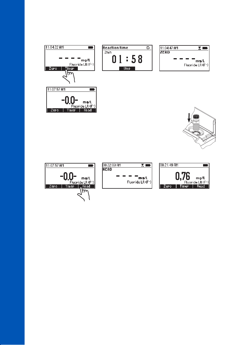
• Press Timer and the display will show the countdown prior to zeroing the blank or wait 2 minutes
and press Zero. The display will show “-0.0-” when the meter is zeroed and ready for measurement.
METHOD PROCEDURES
FLUORIDE LOW RANGE
94
94
94
• Remove the cuvette.
• Insert the second cuvette (#2) with the reacted sample into the
holder and close the lid.
• Press Read to start reading. The instrument displays the results in mg/L of fluoride (F
Note: For wastewater or seawater samples, before performing measurements, distillation
is required. For most accurate results use two graduated pipettes to deliver exactly 8 mL of
deionized water and 8 mL of sample.
INTERFERENCES
Interference may be caused by:
• Alkalinity above 5000 mg/L CaCO
• Chloride above 700 mg/L
• Sulfate above 200 mg/L
• Orthophosphate above 16 mg/L
• Iron (Ferric) above 10 mg/L
• Sodium hexametaphosphate above 1.0 mg/L
• Aluminum above 0.1 mg/L
• Highly colored and turbid samples may require distillation
• Highly alkaline samples can be neutralized with nitric acid
3
# 2
-
).
Page 95
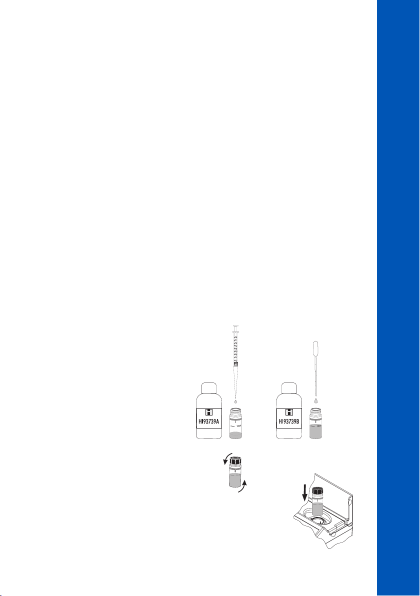
10.25. FLUORIDE HIGH RANGE
METHOD PROCEDURES
FLUORIDE HIGH RANGE
SPECIFICATIONS
Range 0.0 to 20.0 mg/L (as F
Resolution 0.1 mg/L
Accuracy ±0.5 mg/L ±3% of reading at 25 °C
Light Source LED with narrow band interference filter @ 575 nm
Method Adaptation of Standard Methods for the Examination of Water and
Wastewater, 18th Edition, SPADNS Method
REQUIRED REAGENT
Code Description Quantity
HI93739A-0 Fluoride High Range Reagent A 2 mL
HI93739B-0 Fluoride High Range Reagent B 8 mL
REAGENT SETS
HI93739-01 Reagents for 100 tests
HI93739-03 Reagents for 300 tests
For other accessories see ACCESSORIES section.
MEASUREMENT PROCEDURE
• Select the Fluoride HR method using the procedure described in the METHOD SELECTION section.
-
)
#1
• Use 1 mL syringe one and add 2 mL
of HI93739A-0 Fluoride High Range
Reagent A to the cuvette. Use the
pipette to fill up the cuvette to the
10 mL mark with HI93739B-0
Fluoride High Range Reagent B.
• Replace the plastic stopper and the
cap. Invert several times to mix.
• Insert the cuvette into the holder and close the lid.
2 mL
10 mL
95
95
95
Page 96
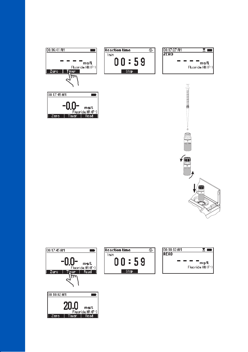
• Press Timer and the display will show the countdown prior to zeroing the blank or wait 1 minute and
press Zero. The display will show “-0.0-” when the meter is zeroed and ready for measurement.
METHOD PROCEDURES
FLUORIDE HIGH RANGE
• Remove the cuvette.
• Add 1 mL of sample to the cuvette using the second 1 mL syringe.
• Replace the plastic stopper and the cap. Invert several times to mix.
• Insert the cuvette into the holder and close the lid.
• Press Timer and the display will show the countdown prior to the measurement or wait 1 minute
and press Read. When the timer ends the meter will perform the reading. The instrument displays
the results in mg/L of fluoride (F
#2
-
).
96
96
96
Page 97

Note: For wastewater or seawater samples, before performing measurements, distillation is
required.
INTERFERENCES
Interference may be caused by:
• Alkalinity above 5000 mg/L CaCO
• Chloride above 700 mg/L
• Sulfate above 200 mg/L
• Orthophosphate above 16 mg/L
• Aluminum above 0.1 mg/L
• Iron (Ferric) above 10 mg/L
• Sodium hexametaphosphate above 1.0 mg/L
• Highly colored and turbid samples may require distillation
• Highly alkaline samples can be neutralized with nitric acid
3
METHOD PROCEDURES
FLUORIDE HIGH RANGE
97
97
97
Page 98
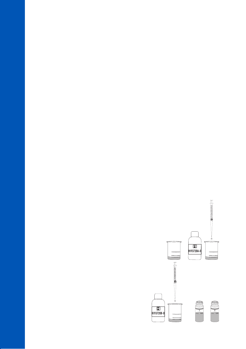
10.26. HARDNESS, CALCIUM
SPECIFICATIONS
Range 0.00 to 2.70 mg/L (as CaCO
Resolution 0.01 mg/L
Accuracy ±0.11 mg/L ±5% of reading at 25 °C
Light Source LED with narrow band interference filter @ 525 nm
Method Adaptation of Standard Methods for the Examination of Water and
Wastewater, 18th Edition, Calmagite Method
HARDNESS, CALCIUM
METHOD PROCEDURES
REQUIRED REAGENTS
Code Description Quantity
HI93720A-0 Calcium Hardness Reagent A 0.5 mL
HI93720B-0 Calcium Hardness Reagent B 0.5 mL
HI93720C-0 Calcium Hardness Reagent C 1 drop
REAGENT SETS
HI93720-01 Reagents for 100 tests
HI93720-03 Reagents for 300 tests
For other accessories see ACCESSORIES section.
MEASUREMENT PROCEDURE
• Select the Hardness (Calcium) method using the procedure described in the METHOD SELECTION
section.
)
3
98
98
98
• Rinse a graduated beaker several times with unreacted
sample, before filling it to the 50 mL mark with the
sample.
• Add 0.5 mL of HI93720A-0 Calcium Hardness Reagent A
and swirl to mix the solution.
• Add 0.5 mL of HI93720B-0 Calcium Hardness Reagent B
and swirl to mix the solution. Fill two cuvettes with 10 mL
of sample (up to the mark).
# 1
# 2
Page 99
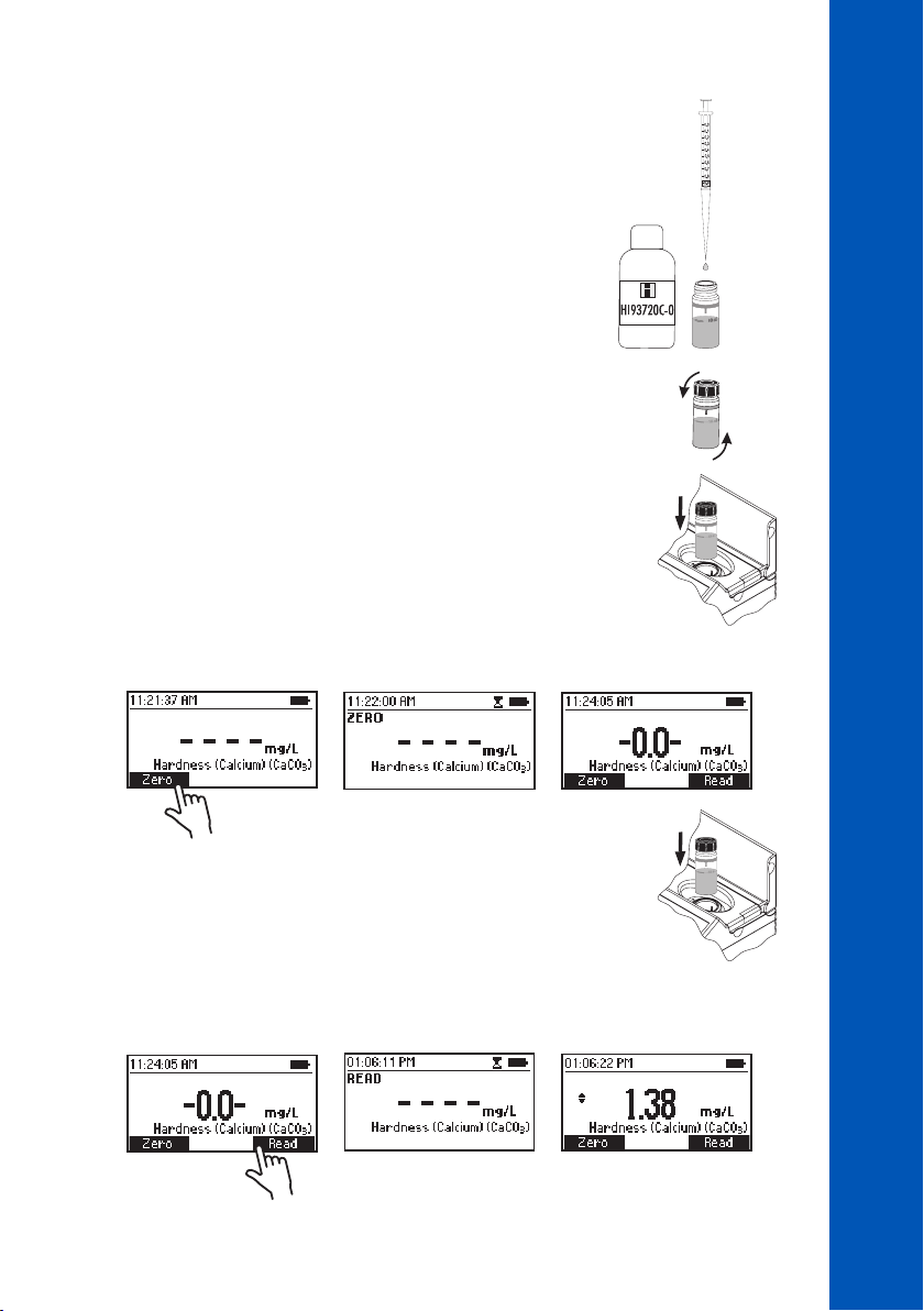
×1
• Add 1 drop of HI93720C-0 Calcium Hardness Reagent C to one
cuvette (#1).
# 1
• Replace the plastic stopper and the cap. Invert the cuvette several
times to mix. This is the blank.
# 1
• Insert the blank (#1) into the holder and close the lid.
• Press Zero. The display will show “-0.0-” when the meter is zeroed and ready for measurement.
METHOD PROCEDURES
HARDNESS, CALCIUM
# 2
• Remove the blank (#1) and insert the second cuvette (#2) into
the holder.
• Press Read to start the reading. The instrument displays concentration in mg/L of calcium
carbonate (CaCO
).
3
99
99
99
Page 100
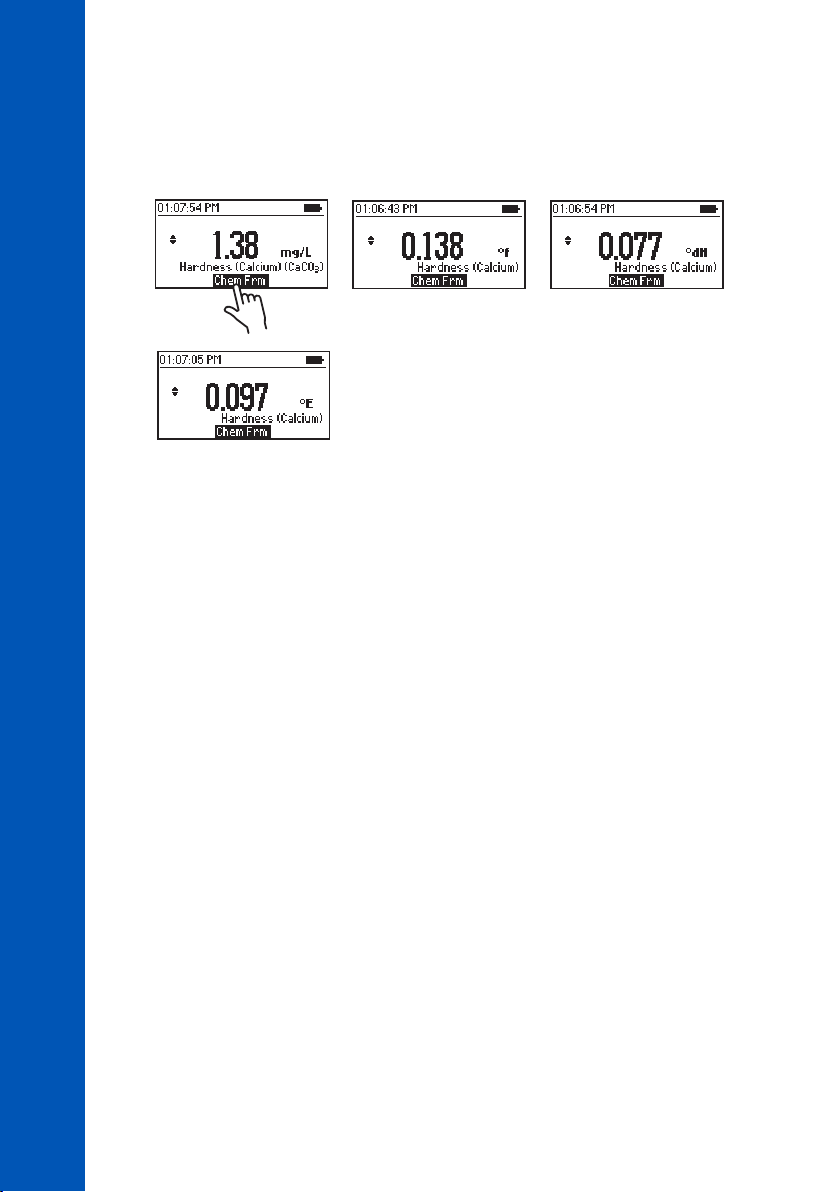
• Press the or key to access the second level functions.
• Press Chem Frm to convert the result to French degrees (°f), German degrees (°dH) and
English degrees (°E).
HARDNESS, CALCIUM
METHOD PROCEDURES
• Press the or key to return to the measurement screen.
Note: This test will detect any calcium contamination in the beaker, measuring syringes or
sample cells. To test cleanliness repeat the test multiple times until you obtain consistent results.
SAMPLE DILUTION
This meter is designed to determine low levels of hardness, typically found in water purification
systems. Dilutions must be performed with hardness-free water or the readings will be erroneous.
To reduce the level of hardness by a factor of one hundred:
• Fill a 1 mL syringe with the sample.
• Add 0.5 mL of sample to a clean, dry 50 mL beaker
• Fill the beaker up to the 50 mL mark with hardness-free water.
100
100
100
INTERFERENCES
Interference may be caused by:
• Excessive amounts of heavy metals
 Loading...