

Page 1
INSTRUCTION MANUAL
VISIBLE
SPECTROPHOTOMETER
HI801
Page 2

Thank you for choosing a Hanna Instruments product.
Please read this instruction manual carefully before using this instrument. This manual will provide you with the necessary
information for the correct use of this instrument, as well as a precise idea of its versatility.
If you need additional technical information, do not hesitate to e-mail us at tech@hannainst.com or view our worldwide
contact list for a Hanna Instruments representative near you at www.hannainst.com.
Dear
Customer,
All rights are reserved. Reproduction in whole or in part is prohibited without the written consent of the copyright owner,
Hanna Instruments Inc., Woonsocket, Rhode Island, 02895, USA.
Page 3

3
TABLE OF CONTENTS
1. PRELIMINARY EXAMINATION .............................................................................................................................................
2. SAFETY MEASURES ...................... .....................................................................................................................................
3. SPECIFICATIONS ...............................................................................................................................................................
4. DESCRIPTION ..... ..............................................................................................................................................................
4.1. GENERAL DESCRIPTION ..............................................................................................................................................
4.2. FUNCTIONAL DESCRIPTION .........................................................................................................................................
4.3. PRINCIPLE OF OPERATION ..........................................................................................................................................
4.4. OPTICAL SYSTEM ........................................................................................................................................................
5. OPERATING MODE ................................................... ........................................................................................................
5.1. START UP ...................................................................................................................................................................
5.2. POWER AND BATTERY MANAGEMENT ...............................................................................................................................
5.3. CUVETTE ADAPTERS....................................................................................................................................................
5.4. METHODS ......................................................................................................................................................................
5.5. TIMERS ..........................................................................................................................................................................
5.6. DATA MANAGEMENT ......................................................................................................................................................
6. SETUP .................................................................................................................................................................................
6.1. METER SETUP ..............................................................................................................................................................
6.1.1. FAVORITE METHODS ...............................................................................................................................................
6.1.2. AUTOMATIC LOG....................................................................................................................................................
6.1.3. METER ID ...............................................................................................................................................................
6.1.4. SAMPLE ID ..............................................................................................................................................................
6.1.5. BEEPER ...............................................................................................................................................................
6.1.6. LCD CONTRAST .......................................................................................................................................................
6.1.7. LETTER SCROLL .......................................................................................................................................................
6.1.8. CSV FIELD SEPARATOR .............................................................................................................................................
6.1.9. DATE AND TIME SETTING...........................................................................................................................................
6.1.10. CUVETTE DETECTION ..............................................................................................................................................
6.1.11. AUTO OFF ..............................................................................................................................................................
6.1.12. FACTORY RESET ...................................................................................................................................................
6.1.13. RESET CONFIGURATION ..........................................................................................................................................
6.2. SYSTEM CHECK ..............................................................................................................................................................
6.2.1. SYSTEM INFO ..........................................................................................................................................................
6.2.2. UPGRADE ................................................................................................................................................................
6.2.3. LAMP CHECK ............................................................................................................................................................
6.2.4. WAVELENGTH CHECK ...............................................................................................................................................
6.2.5. LAMP HISTORY ........................................................................................................................................................
6.3. USB ..............................................................................................................................................................................
6.3.1. METHODS ................................................................................................................................................................
6.3.2. REPORTS ............................................................................................................................................................
6.3.3. CONNECT TO PC ....................................................................................................................................................
6.4. METHOD SETTINGS (USER METHODS ONLY) .....................................................................................................................
6.4.1. MEASUREMENT UNIT ..........................................................................................................................................
6.4.2. NUMBER OF WAVELENGTHS .....................................................................................................................................
6.4.3. WAVELENGTH SETTING ...........................................................................................................................................
6.4.4. DECIMALS .............................................................................................................................................................
5
5
7
7
11
12
13
15
16
6
7
10
12
12
15
16
17
17
17
17
18
18
18
19
19
19
21
21
21
21
21
22
22
22
23
23
22
23
27
24
28
28
28
28
28
Page 4

4
6.4.5. DILUTION FACTOR ..............................................................................................................................................
6.4.6. VIAL TYPE .........................................................................................................................................................
6.4.7. NUMBER OF TIMERS ..........................................................................................................................................
6.4.8. TIMER SETTING ..................................................................................................................................................
6.4.9. MULTI WAVELENGTH FORMULA ..........................................................................................................................
6.4.10. CALIBRATION ...................................................................................................................................................
7. METHODS ......................................................................................................................................................................
7.1. FACTORY METHODS ..................................................................................................................................................
7.2. USER METHODS .......................................................................................................................................................
7.3. FAVORITE METHODS .................................................................................................................................................
7.4. CREATE NEW ............................................................................................................................................................
7.4.1. METHOD NAME ..................................................................................................................................................
8. WARNING AND ERROR MESSAGES.....................................................................................................................................
8.1. WARNING MESSAGES.................................................................................................................................................
8.2. ERRORS.. .................................................................................................................................................................
9. ABBREVIATIONS ..............................................................................................................................................................
10. ACCESSORIES ...............................................................................................................................................................
11. SPARE PARTS ................................................................................................................................................................
11.1. BATTERY REPLACEMENT ..........................................................................................................................................
11.2. LAMP REPLACEMENT ...............................................................................................................................................
RECOMMENDATIONS FOR USERS .........................................................................................................................................
WARRANTY .........................................................................................................................................................................
CERTICICATION.....................................................................................................................................................................
TABLE OF CONTENTS
29
29
30
37
38
39
40
29
32
37
39
39
40
41
42
43
44
44
44
30
46
47
47
Page 5

5
1. PRELIMINARY EXAMINATION
Remove the instrument and accessories from the packaging and examine them carefully to make sure that no damage has occurred
during shipping. Notify your nearest Hanna Customer Service Center if damage is observed.
Each HI801 iris spectrophotometer is supplied with:
• Sample Cuvette and Cap, 22 mm (4 pcs.)
• Cuvette Adapters (3 pcs.)
• Cloth for Wiping Cuvettes
• Scissors
• USB Cable
• Lithium battery
• 15 VDC Power Adapter
• Instruction Manual
• Instrument Quality Certificate
• USB Flash Drive
Note: Save all packing material until you are sure that the instrument works correctly.
Any damaged or defective item must be returned in its original packaging with the accessories supplied.
2. SAFETY MEASURES
• The chemicals contained in the reagent kits may be hazardous if improperly handled.
• Read the Safety Data Sheet (SDS) before performing tests.
• Safety equipment: Wear suitable eye protection and clothing when required, and follow instructions carefully.
• Reagent spills: If a reagent spill occurs, wipe up immediately and rinse with plenty of water. If reagent contacts skin, rinse the
affected area thoroughly with water. Avoid breathing released vapors.
• Waste disposal: For proper disposal of reagent kits and reacted samples, contact a licensed waste disposal provider.
To prevent injury, death or damage to the instrument:
• Use only the power supply, battery and accessories specified in the manual.
• Do not open, disassemble or modify the battery pack or instrument.
• Do not expose the battery or instrument to excess heat.
• Before storing the instrument for an extended period of time, remove the battery pack and disconnect the power plug.
• Do not use or store the battery or instrument in dusty or humid places.
• Do not shake, drop or subject the instrument to physical shock.
• Do not leave the instrument near objects with strong magnetic fields.
To prevent fire or electrical shock:
• Ensure the power adapter is completely plugged in.
• Never handle the power adapter or battery with wet hands.
• Do not leave the battery or meter near a heat source.
• Do not insert any foreign objects in the power adapter connector or battery compartment.
• Do not recharge battery outside ambient temperature conditions (0 to 45 °C).
Note: If the meter experiences a sudden temperature change allow it to equilibrate before turning on. Condensation may have
formed on the instrument and on the internal parts.
PRELIMINARY EXAMINATION SAFETY MEASURES
Page 6

6
SPECIFICATIONS
Wavelength Range 340-900 nm
Wavelength Resolution 1 nm
Wavelength Accuracy ±1.5 nm
Photometric Range 0.000-3.000 Abs
Photometric Accuracy
5 mAbs at 0.000-0.500 Abs
1% at 0.500-3.000 Abs
Measurement Mode
transmittance (%)
absorbance
concentration
Sample Cell
10 mm square
50 mm rectangular
16 mm round
22 mm round
13 mm round (vial)
Wavelength Selection automatic, based on the selected method (editable for user methods only)
Light Source tungsten halogen lamp
Optical System split beam
Wavelength Calibration internal, automatic at power-on with visual feedback
Stray Light <0.1 % T at 340 nm with NaNO
2
Spectral Bandwidth 5 nm
Number of Methods
up to 150 factory (85 pre-loaded)
up to 100 user
Data Points Stored 9999 measured values
Export Capability
csv file format
pdf file format
Connectivity
1x USB A (mass storage host)
1x USB B (mass storage device)
Battery Life 3000 measurements or 8 hours
Power Supply
15 VDC power adapter
10.8 VDC Li-Ion rechargeable battery
Environment
0 to 50 °C (32 to 122 °F);
0 to 95% RH
Dimensions 155 x 205 x 322 mm (6.1 x 8.0 x 12.6")
Weight 3 kg (6.6 Ibs.)
3. SPECIFICATIONS
Page 7
7
DESCRIPTION
4. DESCRIPTION
4.1.GENERAL DESCRIPTION
The HI801 iris visible spectrophotometer is a compact and versatile instrument with a split beam optical system. It features a visible
wavelength range from 340 to 900 nm. The meter features an internal reference system, that reduces errors caused by lamp intensity
and temperature fluctuations. The optical system has been designed to minimize stray light, improving linearity and accuracy.
The spectrophotometer is supplied with 85 factory methods. These methods are pre-programmed with all of the information
necessary to complete an analysis, including the wavelength, vial type, calibration curve and timers. Up to 100 user methods can be
created. Users can select up to 5 wavelengths and timers, cuvette type, and enter their own calibration curves (concentration only).
Calibration curves can contain up to 10 points, with a linear regression curve fit to the data. The slope, offset and R-squared (R2) are
visible for the calibration curve. Both factory and user methods are easily accessible from the main screen using the favorite methods
option.
• Supplied with 85 factory methods
• Create up to 100 user methods
• 5 cuvette types (16 mm round, 22 mm round, 13 mm vial, 10 mm square, 50 mm rectangular) with automatic detection
• Data storage for 9999 measurements with ability to auto log results
• Simplified data transfer to a PC or Mac
• Field upgradeable firmware
• Rechargeable battery
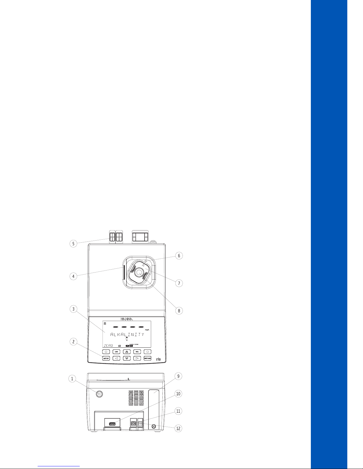
4.2. FUNCTIONAL DESCRIPTION
1) ON / OFF power button
2) Keypad
3) LCD
4) Lid
5) Protective port covers
6) Indexing mark
7) Cuvette adapter
8) Cuvette
9) Battery cover
10) USB connector for USB Flash Drive
11) USB connector for PC connection
12) Power adapter connector
Page 8

8
The keypad contains 8 direct keys and 2 functional keys with the following functions:
Functional keys. Press to perform the function displayed above it on the LCD.
Press to access the METHOD menu.
Press to move up in a menu to increment a value or to access the FAVORITE METHODS from the MAIN SCREEN.
Press to go back to a previous level of the menu, scroll through letter places in the method creation process or to
access the TIMER MENU on the MAIN SCREEN.
Press to move down in a menu or to decrement a set value.
Press to advance in the menu, to scroll through letter places in the method creation setup or to access the CHEMICAL
FORMULAS for factory method on the MAIN SCREEN.
Press to access the SETUP menu.
Press to save the current measurement.
Press to recall logged measurements.
KEYPAD DESCRIPTION
DESCRIPTION
Page 9
9
DESCRIPTION
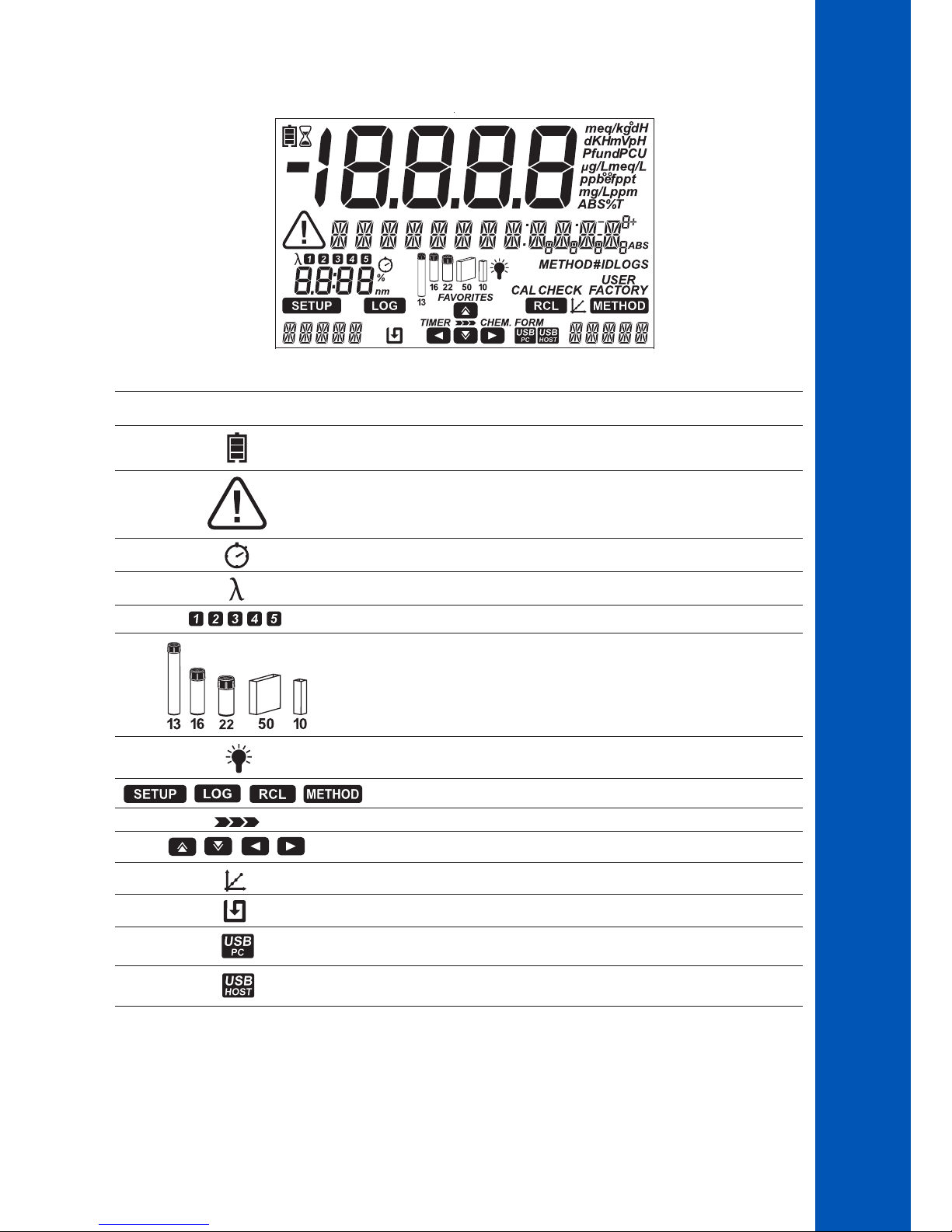
Tag Description
Battery Indicator and Charging Status
Warning Indicator
Timer Indicator
Wavelength Indicator
Tags used to indicate the selected wavelength or timer
Vial type indicator for the selected method*
Lamp Status
Indicates the Active Menu
Indicates Navigation Level in Menus
Indicates Arrow Key is Active
Calibration Indicator
Auto Logging Enabled
PC Connection Established
Flash Drive Connection Established
LCD DESCRIPTION
*Note: For factory methods the indicated vial must be used to obtain valid measurements.
Page 10
10
DESCRIPTION
4.3. PRINCIPLE OF OPERATION
Absorption of light is a typical phenomenon of interaction between electromagnetic radiation and matter.
A spectrophotometer separates electromagnetic radiation (white light) into its component wavelengths and selectively measures the
intensity of the radiation after it passes through a sample.
The white light is passed through a prism to disperse the light into bands of color. These bands of color make up the visible light
spectrum and correlate to the wavelength.
When a light beam crosses a substance, some of the radiation may be absorbed by atoms, molecules or crystal lattices.
If pure absorption occurs, the fraction of light absorbed depends both on the optical path length through the matter and on the
physical-chemical characteristics of the substance according to the Beer-Lambert Law:
T= I/I
o
-log I/Io = el c d
or
A = el c d
T = transmittance
A = absorbance
Io = intensity of incident light beam
I = intensity of light beam after absorption
el= molar extinction coefficient at wavelength l
c = molar concentration of the substance
d = optical path through the substance
The concentration "c" can be calculated from the absorbance of the substance as the other factors are constant.
Photometric chemical analysis is based on specific chemical reactions between a sample and reagent to produce a light-absorbing
compound.
Wavelength (nm) Absorbed Color Transmitted Color
400 violet yellow-green
435 blue yellow
495 green purple
560 yellow blue
650 orange greenish blue
800 red bluish green
I
I
o
Incident light
beam
Transmitted light beam
(light beam after
absorption)
Page 11
11
DESCRIPTION
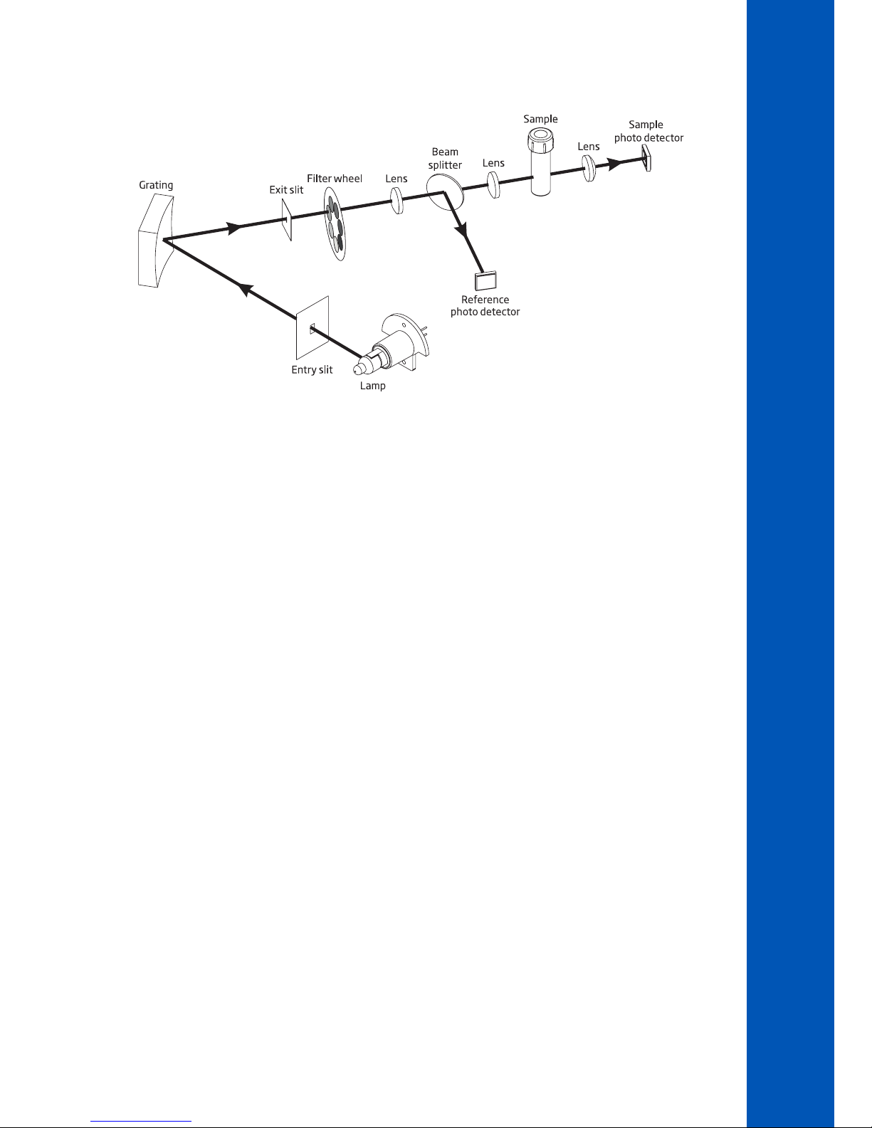
4.4. OPTICAL SYSTEM
Optical System Block Diagram
A tungsten halogen lamp is used as the light source for the entire working range of the meter (340 nm to 900 nm). The tungsten
halogen lamp produces a white light that is passed to a diffraction grating.
The diffraction grating splits the polychromatic white light into the visible color spectrum, allowing for specific wavelengths to be selected.
The light is then passed through an optical filter to reduce stray light and improve measurement accuracy.
The internal reference system uses a reference photo detector to compensate for drifts due to lamp intensity, ambient temperature and
environmental changes, providing a stable source of light.
Focusing lenses are used throughout the optical system to ensure all of the light is being collected. This allows a brighter, stronger signal
to be received.
After the light exits the cuvette a final focusing lens is used. This reduces error from cuvette imperfection and scratches eliminating the
need to index the cuvette.
Page 12
12
5. OPERATING MODE
5.1. START UP
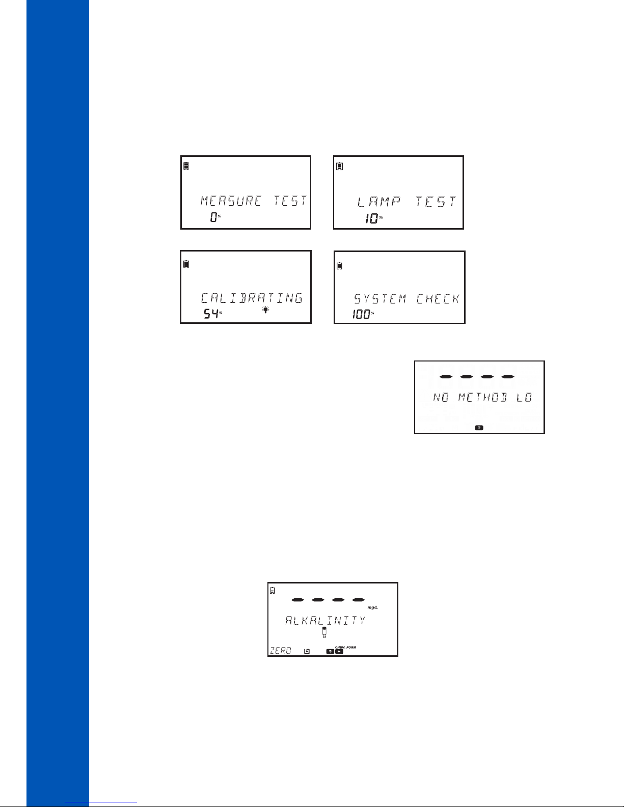
When the instrument is powered on, all the LCD tags will be visible for several seconds before the auto-diagnostic tests run.
This process will take several seconds, during this time the progress will be displayed on the screen. Once these tests are completed
the main screen will be displayed.
These tests ensure that the meter is working properly. If any errors occur a warning message will be displayed.
If there are no methods installed, "No Method Loaded" message is displayed.
5.2. POWER AND BATTERY MANAGEMENT
The meter can be powered from an AC/DC power adapter or from the rechargeable battery.
To conserve power, the auto off option can be enabled in the setup menu, see page 21 for more information. If this option is
enabled, the instrument will automatically turn off after a defined period of time if no interaction has occurred.
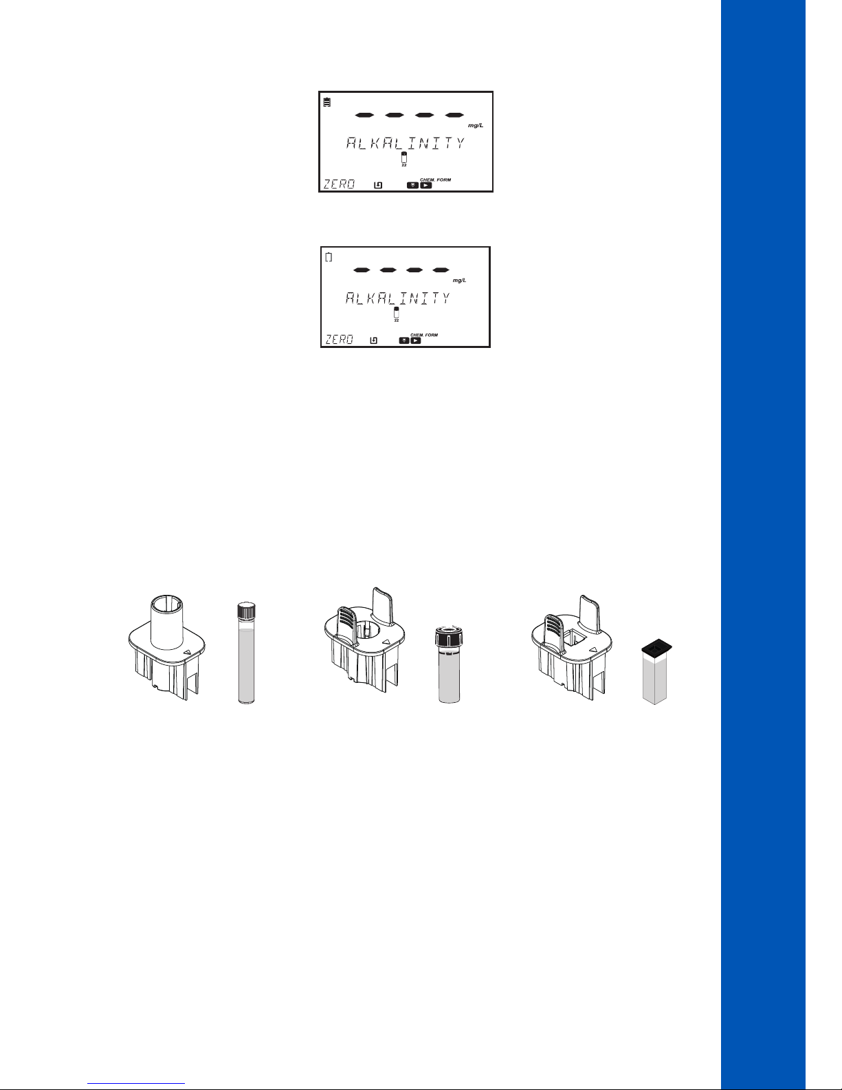
The battery icon on the display will indicate the battery and charging status:
Battery is charging from external adapter
OPERATING MODE
Page 13
13
OPERATING MODE
Battery fully charged (connected to power adapter)
Battery near 0% (no external power adapter)
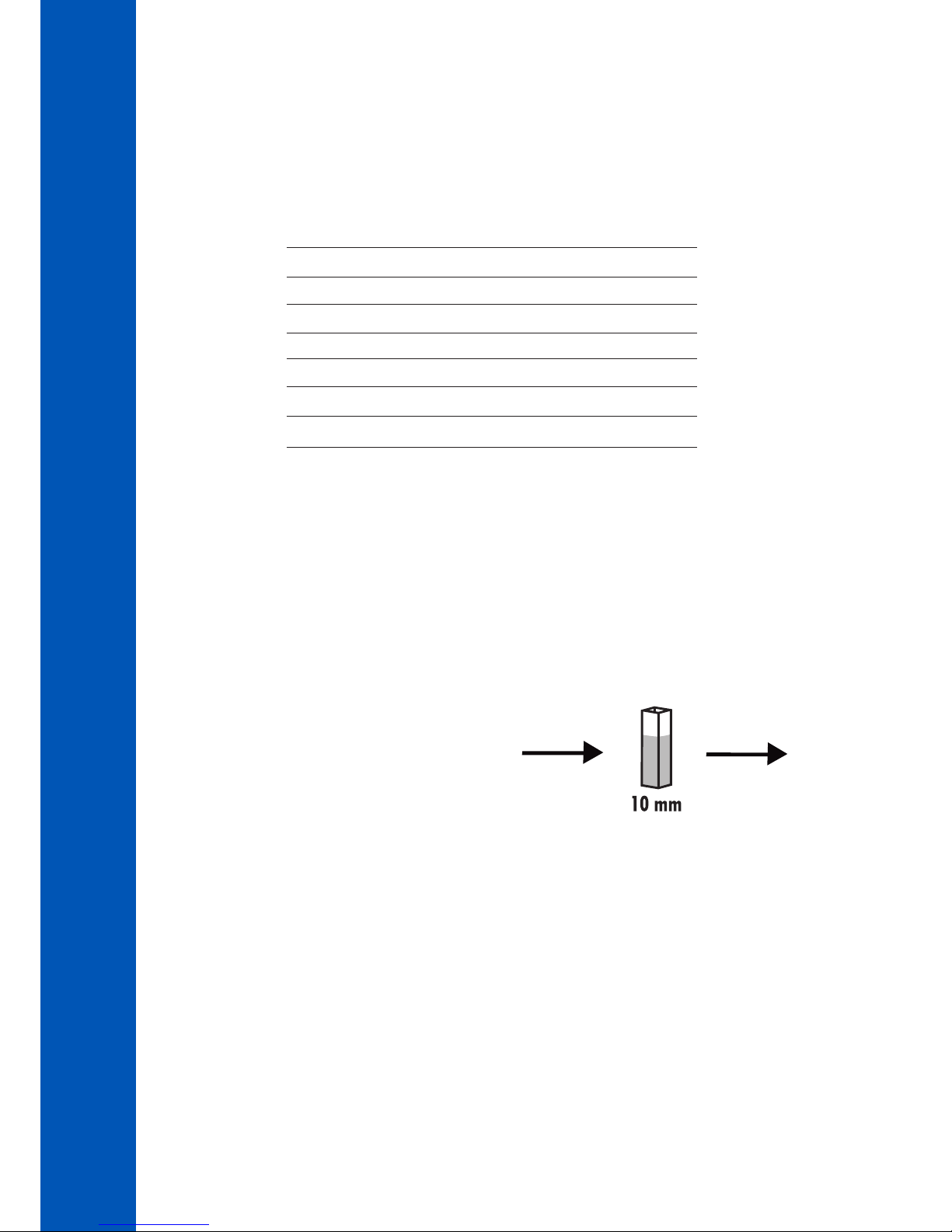
5.3. CUVETTE ADAPTERS
The HI801 iris spectrophotometer is designed to work with five different cuvettes:
• 22 mm round
• 16 mm round
• 13 mm vial
• 10 mm square
• 50 mm rectangular
The meter is supplied with three cuvette adapters:
adapter for 16 mm cuvette
adapter for 10 mm square cuvette
adapter for 13 mm vial
Note: The 22 mm round and 50 mm rectangular cuvettes do not require adapters. The cuvettes can be directly inserted into
the meter.
To prepare the meter for the use of adapters:
1. Open the meter's lid.
2. Select the adapter according to the cuvette type required for the selected method.
3. Orient the adapter so that indexing mark is aligned with the indexing mark located inside the meter.
4. Using light pressure, push the adapter down until it reaches the bottom of the meter's holder.
Page 14

14
OPERATING MODE
5. The meter is ready for use. Always utilize the selected adapter for both "Zero" and "Read" measurements as specified in the
method instructions.
WARNING: Improper use of the vial adapters could cause irreversible damage to the meter. Always use the flowing
precautions when using vial adapters.
•Never use excessive force to insert the adapter. You should be able to insert the vial with light pressure. If the vial
is not reaching the bottom, if there is large resistance, or if you are receiving a “light low” error during the “Zero”
operation, re-check that the indexing marks are aligned on the adapter and meter.
•Never insert hot vials/samples into the vial adapter. Samples should be near room temperature before inserting
into the meter/adapter.
•Do not attempt to close the sample cover while using the 13 mm vials or adapter. It is normal for the vials/
adapter to prevent the cover from closing completely.
Page 15
15
OPERATING MODE
5.4. METHODS
The HI801 iris spectrophotometer can run two different types of methods; factory methods and user methods.
Factory methods were developed by Hanna Instruments. These methods are pre-programmed with all of the information needed
to run an analysis. These methods are calibrated for the selected wavelength, vial type and reagent set, see page 37 for more
information.
User methods are developed by the user. These methods can be customized based on the analysis. Options include multiple
wavelengths, vial type, reaction timers, calibration curves, etc. For additional information for creating new user methods, see
page 39. For additional information about modifying a user method, see page 28.
Factory and User Methods can be tagged as Favorite Methods, if enabled, see page 17 for more information. Favorite Methods are
easily accessible from the main screen by pressing the key.
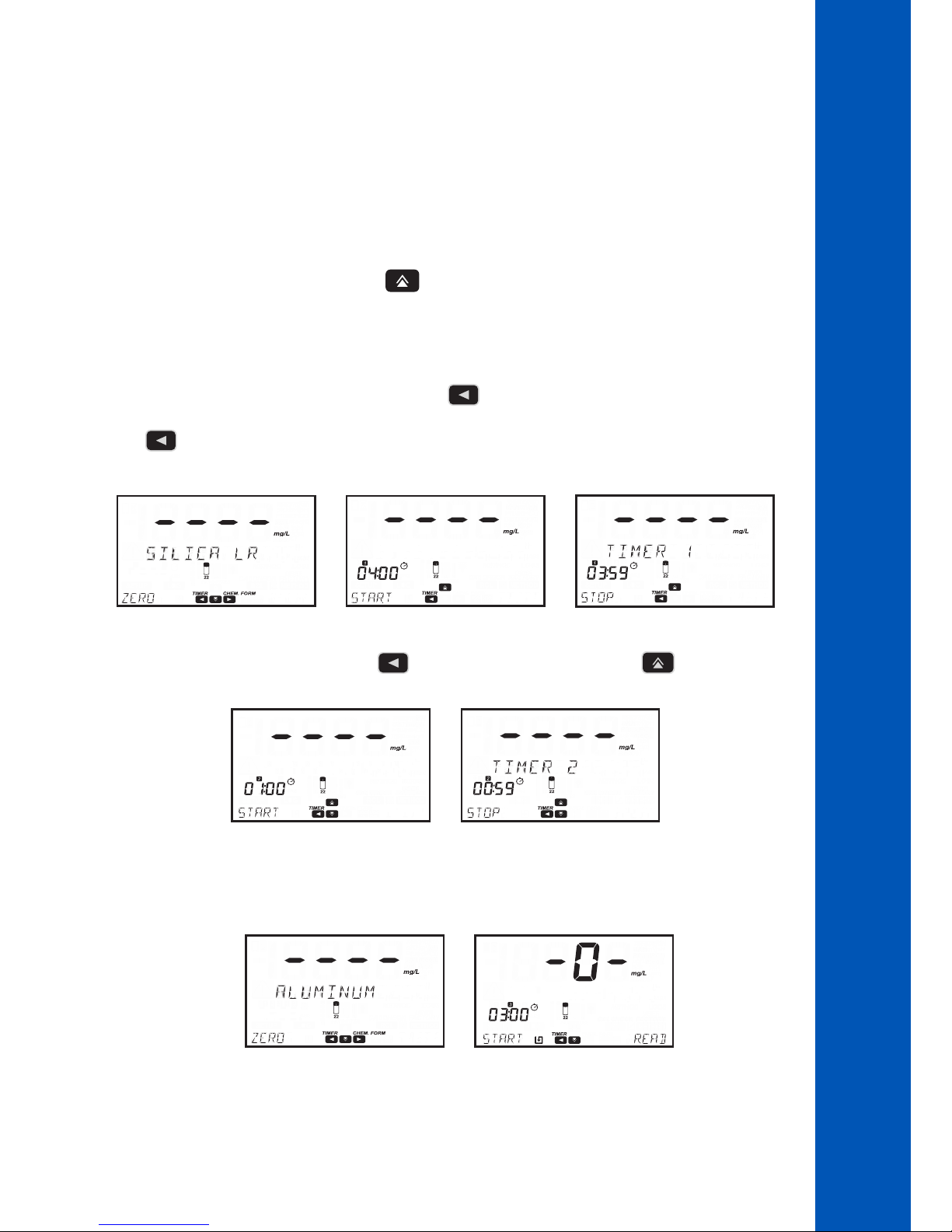
5.5. TIMERS
Each method requires a different measurement procedure.
If a timer or timers is used during the measurement procedure the key will be visible on the main screen with the TIMER tag
above it.
Press the key to access the timer menu. Press the START key to start Timer 1, the display will show the countdown. To stop
and reset the timer, press the STOP key.
If the method requires more than one timer. Press the key to access the timer menu and press the key to select Timer 2 to
Timer 5.
When the timer has expired press the ZERO or READ key to continue. If the timer beeper is enabled a long beep will be heard when
the timer reached "00:00", see page 18 for more information.
Note: A zero measurement must be done before a read measurement. Follow the instructions in the method procedure for
preparation of the zero cuvette.
Page 16

16
OPERATING MODE
5.6. DATA MANAGEMENT
The meter can hold up to 9999 measurements. Data can be reviewed on the screen or transferred to a PC.
LOG DATA
Data can be saved in two different ways:
If Automatic Log is enabled the meter automatically saves the reading. The is shown on the display when this feature is enabled,
see page 17 for more information.
Measurements can also be saved by pressing the key.
If Sample ID is enabled (see page 18 for additional information), the user will be
prompted to enter a unique 2 digit ID for the saved measurement.
The previously entered ID will be displayed automatically.
Press the EDIT key to modify the value. Use the or key to highlight
the digit to be modified.
Press the or key to set the desired value.
Press the CFM key to confirm the Sample ID or the CLR key to return to the previous
screen.
LOG RECALL
Data saved on the instrument can be viewed by pressing the key.
Logs are displayed in order by date and time, the newest log is shown first. Press the key to scroll through the available logs.
Press the INFO key to view additional information for the selected log. The following information is saved for each measurement:
method name, chemical formula (factory methods only), date and time of the measurement, sample ID, method ID, wavelength and
absorbance (user methods only).
Individual logs can be deleted by pressing the CLR key, which prompts a confirmation screen: "Are you sure you want to delete this
log".
DATA TRANSFER
All data stored on the meter can be saved to a PC/Mac or exported to a USB flash drive, see page 23 for more information.
6. SETUP
Press the key to enter the setup menu, use the or key to select the submenu.
The available options are METHOD SETTINGS (if user method is selected, see page 28), METER SETUP, SYSTEM CHECK and
USB.
SETUP
Page 17

17
6.1. METER SETUP
Use the or key to select METER SETUP, press the key to enter the menu.
METER SETUP allows you to modify the meter's general functionality, these settings do not affect the measurement.
6.1.1. FAVORITE METHODS
Option: ON or OFF
When this option is ON methods can be marked as favorites. Favorite methods are
easily accessible on the main screen by pressing the key, see page 38 for more
information. Up to 30 methods can be marked as favorites.
6.1.2. AUTOMATIC LOG
Option: ON or OFF
When this option is ON, measurements are automatically saved in the log.
When this option is OFF, measurements can be added to the log by pressing the
key. When enabled the tag is displayed on the main screen.
6.1.3. METER ID
Option: 0000 to 9999
This option is used to set the instrument's identification number.
Press the EDIT key to set a meter ID.
Use the or key to highlight the digit to be modified. Press the or key to set the desired value. Press the
CFM key to confirm the meter ID or the CLR key to return to the setup menu without saving.
To view the options in the selected submenu press the key
To return to the main screen press the key.
SETUP
Page 18

18
6.1.5. BEEPER
Use the key to access the beeper submenu.
The available options are: KEY PRESS, ERRORS and TIMERS.
KEY PRESS
Option: ON or OFF
If this option is ON, a short beep is heard every time an active key is touched, a
long beep is heard every time an inactive key is touched.
ERRORS
Option: ON or OFF
If this option is ON, a long beep is heard every time an error occurs.
TIMERS
Option: ON or OFF
If this option is ON, a long beep will be heard when a timer reaches "00:00".
6.1.6. LCD CONTRAST
Option: 0 to 7
Press EDIT key to change the displays contrast.
Use the or key to increase or decrease the value.
Press the CFM key to save the value or the CLR key to return to the setup menu
without saving.
SETUP
6.1.4. SAMPLE ID
Option: ON or OFF
If this option is ON the user will be prompted to enter a sample ID when a
measurement is saved.
Page 19

19
SETUP
6.1.7. LETTER SCROLL
Option: LETTER SCROLL or WORD SCROLL
Press the EDIT key to change the scrolling text. Use the or key to select the desired type.
Press the CFM key to save the type or the CLR key to return to the setup menu without saving.
6.1.8. CSV FIELD SEPARATOR
Option: Comma (,) or Semicolon (;)
Press the key to access the submenu.
Press EDIT key to change the type.
Use the or key to select the field separator.
Press the CFM key to confirm the field separator or the CLR key to return to the setup menu without saving.
6.1.9. DATE AND TIME SETTING
Use the key to access the date and time submenu.
The available options are: TIME FORMAT, DATE FORMAT, SET DATE and SET TIME.
TIME FORMAT
Option: 24 H or 12 H
Press the EDIT key to change the time format.
Use the or key to select the desired time format.
Press the CFM key to confirm the time format or the CLR key to return to the previous
screen without saving.
Page 20

20
SETUP
DATE FORMAT
Option: DD/MM/YYYY, MM/DD/YYYY or YYYY/MM/DD
Press the EDIT key to change the date format.
Press the or key to select the desired date format.
Press the CFM key to confirm the date or the CLR key to return to the previous screen
without saving.
SET DATE
Press the EDIT key to modify the date.
Use the or key to highlight the digit to be modified. Press the
or key to set the desired value.
Press the CFM key to save the date or the CLR key to return to the previous screen
without saving.
SET TIME
Press the EDIT key to modify the time.
Use the or key to highlight the digit to be modified. Press the
or key to set the desired value.
Press the CFM key to save the time or the CLR key to return to the previous screen
without saving.
Page 21

21
SETUP
6.1.11. AUTO OFF
Option: OFF, 5, 10, 30 or 60 minutes
This option helps conserve power when the instrument is not being used. If there is
no interaction between the user and the instrument for the set amount of time, the
instrument will automatically turn off to preserve the battery.
If the auto off is set to OFF and the power adapter is removed, the meter will auto
off after 60 minutes unless the power adapter is reconnected.
Press the EDIT key to modify value.
Use the or key to select the desired value.
Press the CFM key to confirm the auto off or the CLR key to return to the setup menu
without saving.
6.1.12. FACTORY RESET
This option will reset the instrument to its factory settings.
Press the CFM key to perform the factory reset.
Press the YES key to continue or the NO key to return to the meter setup menu.
Note: Back up all data before you continue to prevent accidental data loss.
Once this process has been started, it cannot be interrupted or reversed.
The meter will restart when the factory restart is complete.
6.1.13. RESET CONFIGURATION
This option will reset all modifications made in the meter setup. All values will be
reset to default.
Press the CFM key to reset the configuration. Press the YES key to continue or the
NO key to return to the meter setup menu.
6.2. SYSTEM CHECK
Use the or key to select system check, press the to enter the
menu.
System check allows you to view information about the instrument and perform self
diagnostic tests.
6.1.10. CUVETTE DETECTION
Option: On or OFF
If this option is ON, automatic cuvette detection is enabled. If the wrong cuvette
is used an error message will be displayed.
If this option is OFF, the indicated cuvette must be used with the factory methods
to get a valid measurement.
Page 22

22
SETUP
6.2.2. UPGRADE
This option upgrades the firmware.
Press the CFM key to update the firmware.
Insert a USB flash drive containing the update file into the port on the rear of the
meter.
All data will be lost when the firmware is updated. Press the key to return to
menu or the key to continue.
6.2.3. LAMP CHECK
This option performs a diagnostic check on the lamp.
If the lamp passes, the PASS message is displayed on the lower left side of the display.
To start a new test press the CFM key.
Use the key to return to the system check menu.
6.2.4. WAVELENGTH CHECK
This option allows users to check the wavelength positioning using a Holmium Oxide Glass Filter.
Press the CFM key to start the analysis.
Insert the zero cuvette and press the ZERO key.
Insert the holmium oxide filter and press the READ key.
Once the measurement is complete use the and keys to view the
results. The wavelengths corresponding to the found peaks will be displayed on the
lower left side of the screen.
Press the EXIT key to return to the menu.
6.2.1. SYSTEM INFO
This option displays the instrument's serial number, firmware version and baseboard version.
Use the key to access the system info menu.
Use the or key to scroll the displayed information.
Use the key to return to the system check menu.
Page 23

23
SETUP
6.3. USB
Use the or key to select USB, press the key to enter the menu.
Use this menu to import factory methods, import or export user methods, and export logs.
6.3.1. METHODS
Option: Factory Methods or User Methods.
Use the key to access the methods submenu.
Use the or key to scroll through the options.
FACTORY METHODS
Option: Import All
This option allows users to import factory methods from a USB flash drive.
Press the key, Import All will be displayed, insert a USB flash drive containing
the factory methods and press the CFM key. The process will start automatically, the
display will show the progress. To avoid data corruption, do not remove the USB flash
drive until the file transfer is complete.
Press the key to return to the Factory Methods submenu.
6.2.5. LAMP HISTORY
Press the key to view the number of hours the lamp has been running.
Press the RESET key to restart the counter. This should be performed after replacing the lamp.
Use the key to return to the system check menu.
Page 24

24
SETUP
6.3.2. REPORTS
Options: By Sample ID (if enabled), By Method ID, or By Date.
Use the key to access the reports submenu.
USER METHODS
Option: Import All or Export All
This option allows users to import or export all user methods to/from a USB flash drive.
Press the key. Import All will be displayed. Use the or key to
select the desired option. Insert a USB flash drive and press the CFM key. The process
will start automatically, the display will show the progress. To avoid data corruption, do
not remove the USB flash drive until the file transfer is complete.
Exported methods can be transferred to other meters.
Press the key to return to the METHODS menu.
Page 25

25
SETUP
BY SAMPLE ID (if enabled)
This option allows users to generate and export reports by sample ID.
Press the key. The select Sample ID screen is shown.
Press the EDIT key to edit the sample ID. Use the or key to highlight
the digit to be modified. Press the or key to set the desired value.
Press the CFM key to confirm the Sample ID or the CLR key to return to the previous
screen without saving.
Press the key to select the file type. The selected file type will be displayed on
the screen.
Press the EDIT key to change the file type. Use the or to select the
file type. Press the CFM key to confirm the file type or the CLR key to return to the
previous screen without saving.
Press the key to continue. The "Create" message will be displayed.
Press the CFM key to export the file. To avoid data corruption, do not remove the
USB flash drive until the file transfer is complete.
Note: If no USB Flash Drive is connected you will be prompted to connect the flash drive.
BY METHOD ID
This option allows users to generate and export reports by method ID.
Press the key. The select Method ID screen is shown.
Press the EDIT key to edit the method ID. Use the or key to highlight
the digit to be modified. Press the or key to set the desired value.
Press the CFM key to confirm the Method ID or the CLR key to return to the previous
screen without saving.
Page 26

26
Press the key to select the file type. The selected file type will be displayed on
the screen.
Press the EDIT key to change the file type. Use the or to select the
file type. Press the CFM key to confirm the file type or the CLR key to return to the
previous screen without saving.
Press the key to continue. The "Create" message will be displayed.
Press the CFM key to export the file. To avoid data corruption, do not remove the USB
flash drive until the file transfer is complete.
Note: If no USB Flash Drive is connected you will be prompted to connect the
flash drive.
BY DATE
This option allows users to generate and export reports by date.
Press the key. The Start Date screen is shown.
Press the EDIT key to edit the start date. Use the or key to highlight
the digit to be modified. Press the or key to set the desired value.
Press the CFM key to confirm the start date value or the CLR key to return to the
previous screen without saving.
Press the key to select the end date.
Press the EDIT key to edit the end date. Use the or key to highlight the
digit to be modified. Press the or key to set the desired value. Press the
CFM key to confirm the value end date or the CLR key to return to the previous screen
without saving.
SETUP
Page 27

27
Press the key to select the file type. The selected file type will be displayed on
the screen.
Press the EDIT key to change the file type. Use the or to select the
file type. Press the CFM key to confirm the file type or the CLR key to return to the
previous screen without saving.
Press the key to continue. The "Create" message will be displayed.
Press the CFM key to export the file. To avoid data corruption, do not remove the USB
flash drive until the file transfer is complete.
Note: If no USB Flash Drive is connected you will be prompted to connect the flash drive.
6.3.3. CONNECT TO PC
This option allows the instrument to be connected to a PC. Once the instrument is connected reports and user methods can be
imported or exported directly from the unit.
Press the CFM key to enable the connection. The tag and the message "Connected to PC" will be displayed. Use a file manager
(such as Windows Explorer or Mac Finder) to move the files to/from the meter/PC. The meter will appear as a removable disk. To
avoid data corruption, do not remove the USB cable until the file transfer is complete.
Press the STOP key to disconnect the instrument.
SETUP
Page 28

28
6.4.1. MEASUREMENT UNIT
Option: None, %T, ABS, ppm, mg/L, ppt, °f, °e, ppb, meq/L, µg/L, PCU, Pfund, pH, mV, dKH, °dH or meq/kg
This option allows you to select the measurement unit.
Press the EDIT key to select the measurement unit.
Use the or key to select the unit.
Press the CFM key to confirm the unit or the CLR key to return to the method settings
menu without saving.
6.4.2. NUMBER OF WAVELENGTHS
Option: 1 to 5
The option allows you to select the number of wavelengths used in the method
(Except for ABS or %T methods).
Press the EDIT key to change the number of wavelengths.
Use the or key to select the number of wavelengths.
Press the CFM key to confirm the number of wavelengths or the CLR key to return to the method settings menu without saving.
6.4.3. WAVELENGTH SETTING
Options: 340 to 900 nm
This options allows you to set the wavelength.
Press the EDIT key to modify the wavelength.
Use the or key to highlight the digit to be modified. Press the
or key to set the desired value.
Press the CFM key to confirm the set wavelength or the CLR key to return to the method settings menu without saving.
Note: Use the key to view additional wavelengths (if enabled).
6.4.4. DECIMALS
Option: 0 to 3
This option allows the user to set the measurement resolution (xxxx, xxx.x, xx.xx or x.xxx).
Resolution for absorbance (ABS) and transmittance (%T) are fixed and cannot be
modified.
Press the EDIT key to select the number of decimals.
Use the or key to select the number of decimals.
Press the CFM key to confirm the number of decimals or the CLR key to return to the method settings menu without saving.
SETUP
6.4. METHOD SETTINGS (USER METHODS ONLY)
Method Settings allows you to modify the settings and calibration curve for to the selected user method. These settings affect the
measurement.
Page 29

29
6.4.5. DILUTION FACTOR
Option: 001 to 100
This option allows the user to set the dilution factor used in sample preparation. This
allows samples with high concentrations that are outside the measurement range to
be measured. If the sample is not diluted enter a factor of 001.
Press the EDIT key to modify the dilution factor.
Use the or key to highlight the digit to be modified. Press the
or key to set the desired value.
Press the CFM key to confirm the dilution factor or the CLR key to return to the method settings menu without saving.
SETUP
6.4.6. VIAL TYPE
Option: 10mm, 13mm, 16mm, 22mm or 50 mm
This option allows the user to select the vial used for measurement.
Press the EDIT key to select the vial type.
Use the or key to select the vial.
Press the CFM key to confirm the vial type or the CLR key to return to the method settings menu without saving.
6.4.7. NUMBER OF TIMERS
Option: 0 to 5
The option allows you to select the number of timers used in the method.
Press the EDIT key to select the number of timers.
Use the or key to select the number of timers.
Press the CFM key to confirm the number of timers or the CLR key to return to the
method settings menu without saving.
Page 30

30
6.4.8. TIMER SETTING
Option: 00:00 to 59:59
This options allows you to select the timer length.
Press the EDIT key to modify the time.
Use the or key to highlight the digit to be modified. Press the
or key to set the desired value.
Press the CFM key to confirm the time or the CLR key to return to the method
settings menu without saving.
Press the ENTER key to modify the timer name.
Press the EDIT key to modify the name.
Use the or key to highlight the character to be modified. Press the
or key to set the desired character.
Press the CFM key to confirm the timer name or the CLR key to return to the method
settings menu without saving.
Press the EXIT key to return to the timer screen.
Note: Use the key to view additional timers (if enabled).
6.4.9. MULTI WAVELENGTH FORMULA
This option is only available if the selected method uses more than 1 wavelength.
The final result can be calculated using equations with editable coefficients.
EQUATIONS:
The following equations can be used to calculate the final result.
Formula Sum:
Formula Fraction:
Formula A 1:
Formula A 2:
Formula A 3:
Formula A 4:
Formula A 5:
Press the EDIT key to select the equation.
Use the or to select the equation.
Press the CFM key to save the selection or the CLR key to return to the method settings.
Note: The multiwavelength formula is not available for ABS and %T unit selected.
C= P1A1+ P2A2+ P3A3+ P4A4+P5A
5
C=P1A
1
C=P2A
2
C=P3A
3
C=P4A
4
C=P5A
5
SETUP
C = Concentration
A1 to A5 = Absorbance at specified wavelength
P1 to P5 and Q1 to Q6 = Factors
U n t it le d 1
C=
P
1A1
+ P2A2+ P3A3+ P4A4+ P5A
5
Q1A1+Q2A2+Q3A3+Q4A4+Q5A5+Q
6
Page 31

31
FACTORS
The meter will only display and use the factor needed for the selected equation.
Use the or to select the factor.
Press the EDIT key to modify the value.
Use the or key to highlight the digit to be modified. Press the or keys to set the desired value.
To shift the number (along with the decimal point) to the right use the key to highlight the digit furthest to the left and press
the key, 9.876 will become 09.87, then 009.8, and 0009.
...
To make the number negative use the key to highlight the digit furthest to the left and press key to decrement the
value.
To shift the number (along with the decimal point) to the left use the key to highlight the digit furthest to the right and press
the key, -0009 will become -009.8, then -09.87, and -9.876, this can be done as long as you have leading zeros available.
SETUP
...
...
The digit furthest to the left takes values from -9 to 9 by pressing the or keys, while the other digits are cyclic and
take values from 0 to 9.
Page 32

32
SETUP
6.4.10. CALIBRATION
Option: Measure Standards or Manual ABS Entry
This option allows users to calibrate user methods by measuring the absorbance of known standards or manually entering absorbance
values. Calibrations can contain up to 10 points.
Note: This option is only available if a concentration unit is selected (i.e. mg/L, meq/kg, etc.). A calibration cannot be entered
for methods using absorbance or % transmittance or multiwavelength methods. This option is only available for user methods.
Factory methods have pre-programmed calibration curves based on the wavelength, cuvette type and reagent set.
A calibration is required to run a new user method.
Press the key to enter the menu. Use the or to select the desired option.
Press the key to return to the calibration menu.
Once a method has been calibrated the will be displayed on the main screen when the method is selected. If a user method has
not been calibrated the error message "Not Calibrated" will be displayed.
MEASURE STANDARDS
This allows users to measure the absorbance of standards with a known concentration. Up to 10 points can be used to calibrate the
method.
Press the CFM key to start the calibration.
Press the EDIT key to modify the concentration for the first standard.
Use the or key to highlight the digit to be modified. Press the or keys to set the desired value.
Press CFM to confirm the value or CLR to delete set value.
Press the or key to abort the calibration.
Page 33

33
Press NO to return to the last calibration point screen or press YES to exit calibration.
Press the CFM key to continue.
Insert the zero cuvette and press the ZERO key.
Insert the first standard and press the READ key.
Press the CFM key to save the value and continue or the REDO key to repeat the measurement.
Press the key or to abort the calibration.
Press the DONE key to save and exit the calibration or the MORE key to add additional points.
When wrong slope or offset occurred the meter will display an error message:
SETUP
Page 34

34
SETUP
Edit concentration point Measure Abs point
.
.
.
.
.
.
This procedure can be repeated until 10 calibration points have been added.
MANUAL ABS ENTRY
This allows users to enter the absorbance of standards with a known concentration. Up to 10 points can be used to calibrate the
method.
Press the CFM key to start the calibration.
Press the EDIT key to modify the concentration for the first standard.
Use the or key to highlight the digit to be modified. Press the or keys to set the desired value. Press
CFM to confirm the value or CLR to delete set value. Press the or key to abort calibration.
Press the CFM key to continue.
Page 35

35
Press the EDIT key to modify the absorbance for the first standard.
Use the or key to highlight the digit to be modified. Press the or keys to set the desired value. Press
CFM to confirm the value or CLR to return to the method settings menu without saving. To set a negative abs value highlight the first
digit and use or to select designed value.
Press the CFM key to save the value.
Press the DONE key to save and exit the calibration or the MORE key to add additional points.
This procedure can be repeated until 10 calibration points have been added.
Edit concentration point Edit Abs point
.
.
.
.
.
.
SETUP
Page 36

36
VIEW CALIBRATION
After a calibration has been completed the calibration data can be viewed using View
Calibration. A linear regression is done by the instrument for the saved calibration
points, the meter will apply the best straight-line fit to the calibration points. The
available options are: SLOPE, OFFSET, R-SQUARED, and CALIBRATION POINTS.
Press the CFM key to view the calibration information.
Use the or to scroll through the options.
Press the to return to the previous screen.
DELETE CALIBRATION
To delete a previous saved calibration use the or to select Delete Calibration.
Press the CFM key, and the YES key to continue or the NO key to return to the Calibration menu.
A new calibration is required before the method can be run.
SETUP
Page 37

37
METHODS
7. METHODS
Option: FACTORY METHODS, USER METHODS, FAVORITE METHODS (if enabled) and CREATE NEW
In order to run an analysis a method needs to be loaded.
Use the or key to scroll through the available options.
The number of methods will be displayed on the lower left side of the screen.
Press the key to return to the main screen.
7.1. FACTORY METHODS
Up to 150 factory methods can be stored on the instrument. Use the or key to scroll through the methods. To view
the methods by ID press the VIEW key. Press the CFM key to load the selected method.
To view the ordering information, method version or to mark the method as a favorite (if enabled) press the key.
Use the or to view the available options.
To view the ordering information press the CFM key when "Ordering Info" is displayed.
To add a method to the favorites list press the CFM key when "Set Favorite" is displayed. If the method is already tagged as a
favorite "Clear Favorite" is displayed.
Press the key to return to the method list.
Page 38

38
METHODS
7.2. USER METHODS
Up to 100 user methods can be stored on the instrument. Use the or key to scroll through the methods. To view the
methods by ID press the VIEW key. Press the CFM key to load the selected method.
To view additional information press the key.
Use the or to view the available options.
To add a method to the favorites list press the CFM key when "Set Favorite" is displayed. If the method is already tagged as a
favorite "Clear Favorite" is displayed.
To delete the selected method press the CFM key when "Delete" is displayed.
To rename the selected method press the CFM key when "Rename" is displayed,
see page 39 for additional information.
To export the selected method press the CFM key when "Export" is displayed, see
page 23 for additional information.
Page 39

39
7.3. FAVORITE METHODS
Frequently used methods can be tagged as a favorite method, see page 17 for additional information. Favorite methods can be both
factory and user methods. Up to 30 methods can be tagged as favorites.
Once a method has been tagged as a favorite it will appear in the Favorite Method list for easy access when the key is pressed.
Favorite Methods can also be easily accessed from the main screen by pressing the key.
7.4. CREATE NEW
This options allows users to develop new user methods.
Press the CFM key to create a new method. A series of prompts will guide the user through the process of creating a new method.
Press NEXT to proceed to the next setting.
Press BACK to return to the previous setting.
7.4.1. METHOD NAME
Option: Up to 12 alphanumeric characters
Use the or key to select the desired character. Press the or
key to move across characters.
Press the NEXT key to save and continue or the BACK key to return to the methods
menu.
For more information on the settings and options that are available during method creation, see section 6.4 Method Settings.
METHODS
After all settings have been entered, press the CFM key to create the method. The
meter will show "Method Created" before returning to the main screen.
All of these settings can be modified in method settings, see page 28 for additional
information.
In order to use the newly created method that reports in a concentration unit a
calibration must be done.
A calibration is not required for methods reporting in absorbance, % transmittance or
multiwavelength.
Page 40

40
8. WARNING AND ERROR MESSAGES
8.1. WARNING MESSAGES
FACTORY METHODS FULL The maximum number of factory methods have been added.
USER METHODS FULL
The maximum number of user methods have been added. At least 1 user method
needs to be deleted before a new one can be created.
FAVORITE METHODS FULL The maximum number of favorite methods have been added.
METHOD MISSING OR CORRUPT Method file corrupted.
FILE MISSING OR CORRUPT Log file corrupted.
DISK FULL FACTORY Factory partition full.
DISK FULL
The maximum number of logs have been saved. At least 1 log needs to be deleted
before a new one can be created.
FLASH NOT SUPPORTED USB flash drive not supported.
FLASH REMOVED The USB flash drive is missing or cannot be read.
LOG CORRUPTED Log file corrupted.
NO LIGHT The Light Source is not functioning properly. Replace the lamp or check the wiring.
LOW LIGHT
The instrument cannot adjust the light level. Please check that the sample does not
contain any debris.
LIGHT HIGH
There is too much light to perform a measurement. Please check the preparation of
the zero cuvette.
REFERENCE ERROR There is a problem with the reference chanel.
CLOSE THE LID The lid is not properly closed.
INVERTED CUVETTES
The sample and the zero cuvettes are were measured in the wrong order, or there
is a problem with the cuvette preparation.
WRONG OR MISSING CUVETTE
Wrong cuvette inserted. The cuvette does not match the one specified in the
method.
NOT CALIBRATED A calibration is required before a user method can be used.
INVALID CALIBRATION
The calculated slope for the calibration curve is outside of allowed range. Please
repeat the calibration.
HIGH TEMPERATURE The internal temperature is higher then 55 °C.
LOW TEMPERATURE The internal temperature is lower then 0 °C.
LAMP OLD - REPLACE SOON The lamp life is over recommended maximum period. Consider replacing the lamp.
WARNING AND ERROR MESSAGES
Page 41

41
WARNING AND ERROR MESSAGES
8.2. ERRORS
These types of events are continuously monitored and if one or more occurred it will put the instrument in ERROR mode to
avoid unpredictable behavior.
The "Err" is displayed on LCD, followed by the internal code of the error. This screen will block the access to the other screens.
If a system error occurs, contact Hanna Technical Support and provide the displayed code.
Page 42

42
ABBREVIATIONS
EPA US Environmental Protection Agency
ºC degree Celsius
ºF degree Fahrenheit
μg/L micrograms per liter (ppb)
mg/L milligrams per liter (ppm)
%T Percent Transmittance
ABS Absorbance
ppm parts per million (mg/L)
ppt parts per thousand (g/L)
ppb parts per billion (μg/L)
ºf French degree (Hardness)
ºe English degree (Hardness)
ºdH German degree (Hardness)
meq/L milliequivalents per liter
meq/kg milliequivalents per kilogram
PCU Platinum Cobalt Unit
Pfund honey color grading scale in millimeters
pH Negative log of the hydrogen ion activity
mV Millivolts
dKH Degrees of Carbonate Hardness
9. ABBREVIATIONS
Page 43

43
ACCESSORIES
10. ACCESSORIES
Code Description
HI7408011 16 mm cuvette adapter
HI7408012 10 mm cuvette adapter
HI7408013 13 mm vial adapter
HI7408014 replacement lamp
HI7408015 replacement battery
HI7408016 USB Flash Drive
HI75110/15 115 VAC to 15 VDC power adapter, USA plug
HI75220/15 230 VAC to 15 VDC power adapter, European plug
HI920013 USB cable for PC connection
HI731318 cloth for wiping cuvettes (4 pcs.)
HI731331 22 mm glass cuvettes (4 pcs.)
HI731335N cap for 22 mm cuvette (4 pcs.)
HI731311 13 mm vials (5 pcs.)
HI731321 16 mm glass cuvettes (4 pcs.)
HI731335N cap for 16 mm cuvette (4 pcs.)
HI731339P 100 μL automatic pipette
HI731340 200 μL automatic pipette
HI731341 1000 μL automatic pipette
HI731342 2000 μL automatic pipette
HI731349P pipette tip for 100 μL graduated pipette (10 pcs.)
HI731350 pipette tip for 200 μL graduated pipette (25 pcs.)
HI731351 pipette tip for 1000 μL graduated pipette (25 pcs.)
HI731352 pipette tip for 2000 μL graduated pipette (4 pcs.)
HI740034P cap for 100 mL beaker (10 pcs.)
HI740036P 100 mL plastic beaker (10 pcs.)
HI740038 60 mL glass bottle and stopper for dissolved oxygen measurements
HI740142P 1 mL graduated syringe (10 pcs)
HI740143 1 mL graduated syringe (6 pcs.)
HI740144P pipette tip for 1 ml graduated syringe (6 pcs.)
HI740157P plastic refilling pipette (20 pcs.)
HI740220 25 mL glass mixing vial (2 pcs.)
HI740225 60 mL graduated syringe
HI740226 5 mL graduated syringe
HI740227 filter assembly
HI740228 filter discs (25 pcs.)
HI740230 demineralized water (230 mL)
DEMI-02 demineralizer
HI740228 filter discs (25 pcs.)
HI93703-50 cuvette cleaning solution (230 mL)
HI93703-55 activated carbon (50 pcs.)
HI83300-100 Sample preparation kit consisting of activated carbon for 50 tests, demineralizer bottle for 10 L of
water, 100 mL graduated beaker with cap, 170 mL graduated beaker with cap, 3 mL pipette, 60 mL
syringe, 5 mL syringe, graduated cylinder, spoon, funnel, filter paper (25 pcs.).
HI839800-01 reactor, 230 VAC to 15 VDC power adapter, European plug
HI839800-02 reactor, 115 VAC to 15 VDC power adapter, USA plug
Page 44

44
SPARE PARTS
11. SPARE PARTS
11.1. BATTERY REPLACEMENT
To replace or remove the battery use a Phillips head screwdriver to loosen the screw in the base of the battery cover (a).
Remove the battery cover (b).
Pull the battery out (c).
Always check the polarity when reinserting. The positive (+) sign should be on the top (d).
(a) (b)
(c) (d)
Page 45

45
To replace the Tungsten Halogen Lamp follow the steps below:
(a) Connect the lamp cable to the new lamp
(b) Align the lamp with the screw holes in the base of the instrument
(c) Insert the lamp holder into the optical system, making sure the cable is not pinned between the optical system and holder.
(d) Tighten the two screws in the base of the lamp holder and push the power cable back into the instrument.
(e) Replace the cover and secure the screw.
(f) Power on the instrument.
(b) (c)
SPARE PARTS
11.2. LAMP REPLACEMENT
Only hold the lamp by the metal holder.
DO NOT TOUCH THE PINS OR THE QUARTZ GLASS!
Ensure the instrument is off before continuing.
To remove the Tungsten Halogen Lamp follow the steps below.
(a) Use a Phillips head screwdriver to remove the screw on the lamp cover and remove the cover.
(b) Remove the two screws in the bottom on the lamp holder using a Phillips head screwdriver.
(c) Hold the bottom of the lamp holder and slowly pull the lamp out.
(d) Disconnect the lamp cable before removing the lamp completely.
(a)
Page 46

Before using this product make sure that they are entirely suitable for your specific application and for the
environment in which they are used.
Operation of these instruments may cause interferences to other electronic equipment. Take all necessary steps
to correct such interferences. Any variation introduced by the user to the supplied equipment may degrade the
instruments EMC performance.
For yours and the instrument safety do not use or store the instrument in hazardous environments.
Recommendations
for Users
MAN801 10/17
Page 47

The HI801 iris spectrophotometer is warranted for two years against defects in workmanship and materials when used for
its intended purpose and maintained according to instructions. This warranty is limited to repair or replacement free of charge.
Damage due to accidents, misuse, tampering or lack of prescribed maintenance is not covered. If service is required, contact
your local Hanna Instruments Office. If under warranty, report the model number, date of purchase, serial number and
the nature of the problem. If the repair is not covered by the warranty, you will be notified of the charges incurred. If the
instrument is to be returned to Hanna Instruments, first obtain a Returned Goods Authorization number from the Technical
Service department and then send it with shipping costs prepaid. When shipping any instrument, make sure it is properly
packed for complete protection.
Warranty
Hanna Instruments reserves the right to modify the design, construction or appearance of its products without advance notice.
Certification
This product conforms with all European Directives for Laboratory Devices.
Disposal of Electrical & Electronic Equipment. The product should not be treated as household waste. Instead hand
it over to the appropriate collection point for the recycling of electrical and electronic equipment which will conserve
natural resources.
Disposal of waste batteries. This product contains batteries, do not dispose of them with other household waste.
Hand them over to the appropriate collection point for recycling.
Ensuring proper product and battery disposal prevents potential negative consequences for the environment and human
health, which may be caused by inappropriate handling. For more information, contact your city, your local household
waste disposal service, the place of purchase or go to www.hannainst.com.
RoHS
compliant
Page 48

MAN801
World
Headquarters
Hanna Instruments Inc.
Highland Industrial Park
584 Park East Drive
Woonsocket, RI 02895 USA
www.hannainst.com
Local Office
HannaNorden AB
Energigatan 15 B
SE-434 37 Kungsbacka
SWEDEN
Phone: +46 300 404018
Fax: +46 300 14122
e-mail: infp@hannanorden.com
Printed in ROMANIA
 Loading...