

Page 1

Instruction Manual
HI 720
Conductivity
Process Controller
with Inductive Probe
www.hannainst.com
1
Page 2

TABLE OF CONTENTS
WARRANTY .....................................................................................................4
PRELIMINARY EXAMINATION ............................................................................5
MODEL IDENTIFICATION..................................................................................5
GENERAL DESCRIPTION & THEORY OF OPERATION ..........................................6
SPECIFICATIONS ..............................................................................................9
FUNCTIONAL DESCRIPTION ........................................................................... 10
INSTALLATION ................................................................................................12
OPERATIONAL GUIDE.................................................................................... 14
• SETUP MODE ..........................................................................................14
• CALIBRATION MODE ............................................................................... 34
• CONTROL MODE .................................................................................... 37
• IDLE MODE ............................................................................................. 43
• LAST CALIBRATION DATA VIEWING MODE ................................................. 43
• DIAGNOSTIC MODE ............................................................................... 44
TEMPERATURE COMPENSATION ..................................................................... 46
CONCENTRATION CURVES ............................................................................ 48
HOLD MODE ................................................................................................ 50
IN-LINE CLEANING ........................................................................................ 52
COMMUNICATION ........................................................................................54
• PC COMMUNICATION ............................................................................ 54
• SHORT MESSAGING SERVICE (SMS) .......................................................... 67
• MODEM CONNECTION ..........................................................................71
ERRORS - FAULT CONDITIONS ....................................................................... 73
ALARM - ERROR CONFIGURATION ................................................................. 74
SELFTEST PROCEDURES ..................................................................................77
ACCESSORIES ................................................................................................ 80
2
3
Page 3
Dear Customer,
Thank you for choosing a Hanna Instruments product.
Please read this instruction manual carefully before using the instrument. It will
provide you with the necessary information for correct use of the instrument, as
well as a precise idea of its versatility.
If you need additional technical information, do not hesitate to e-mail us at
tech@hannainst.com or see the back cover for our worldwide contact list.
This instrument is in compliance with the CE directives.
PRELIMINARY EXAMINATION
Remove the instrument from the packing material and examine it carefully to
make sure that no damage has occurred during shipping. If there is any noticeable damage, notify your Dealer or the nearest Hanna Customer Service Center
immediately.
Note Save all packing materials until you are sure that the instrument
functions correctly. Any damaged or defective items must be returned
in their original packing materials together with the supplied accessories.
WARRANTY
All Hanna Instruments meters are guaranteed for two years (sensors,
electrodes and probes for six months) against defects in workmanship and
materials when used for their intended purpose and maintained according to
instructions.
This warranty is limited to repair or replacement free of charge. Damage due to
accident, misuse, tampering or lack of prescribed maintenance are not covered.
If service is required, contact the dealer from whom you purchased the instrument. If under warranty, report the model number, date of purchase, serial number and the nature of the failure.
If the repair is not covered by the warranty, you will be notified of the charges
incurred.
If the instrument is to be returned to Hanna Instruments, first obtain a Returned
Goods Authorization number from the Customer Service department and then
send it with shipping costs prepaid.
When shipping any instrument, make sure it is properly packaged for complete
protection.
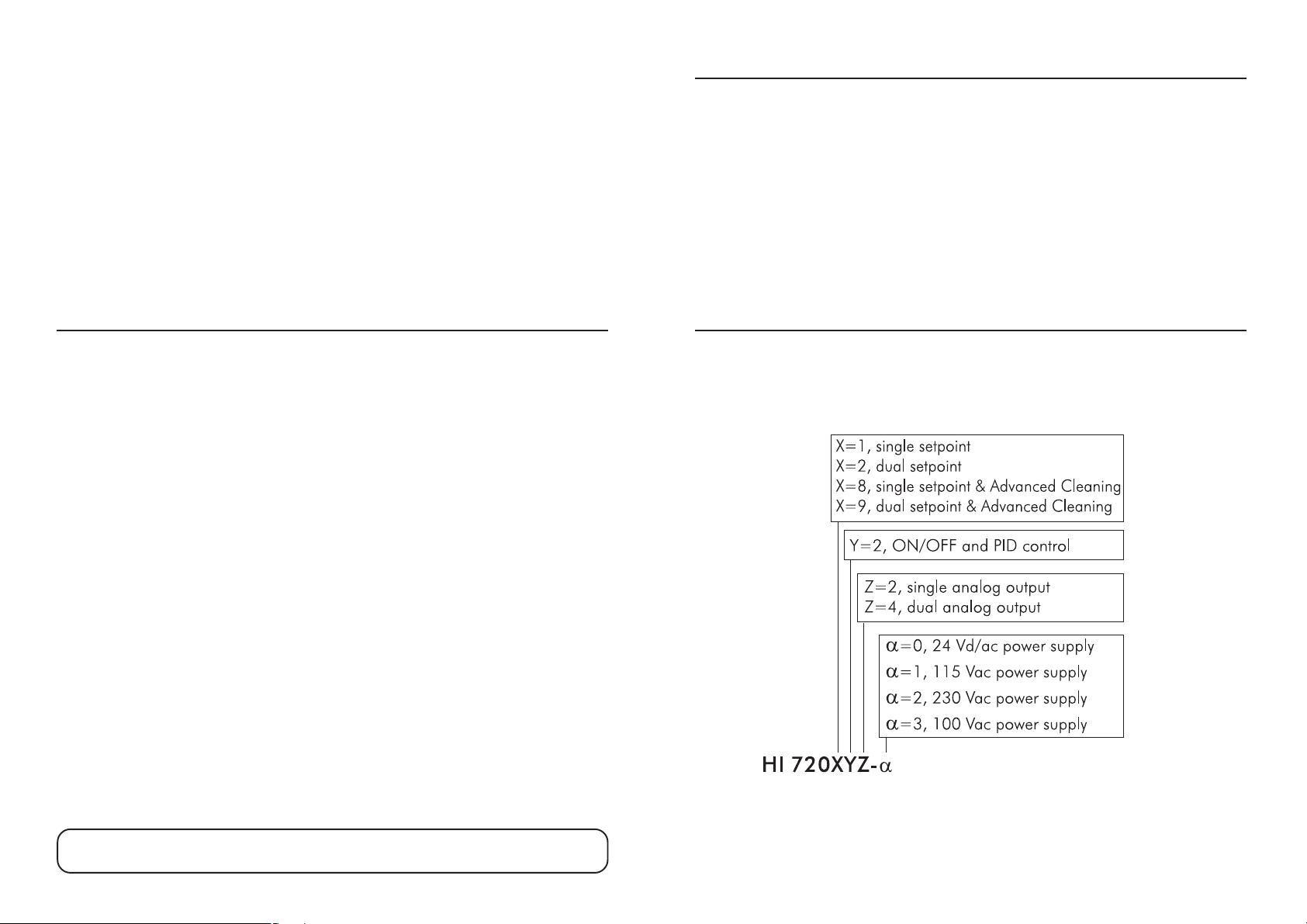
MODEL IDENTIFICATION
The models HI 720 XYZ-
The meaning of the last letters is according to the following scheme:
αα
α are conductivity controllers.
αα
Hanna Instruments reserves the right to modify the design,
construction and appearance of its products without advance notice.
4
5
Page 4
GENERAL DESCRIPTION & THEORY OF OPERATION
This instrument allows conductivity measurements without any electrical contact
between electrodes and process fluid.
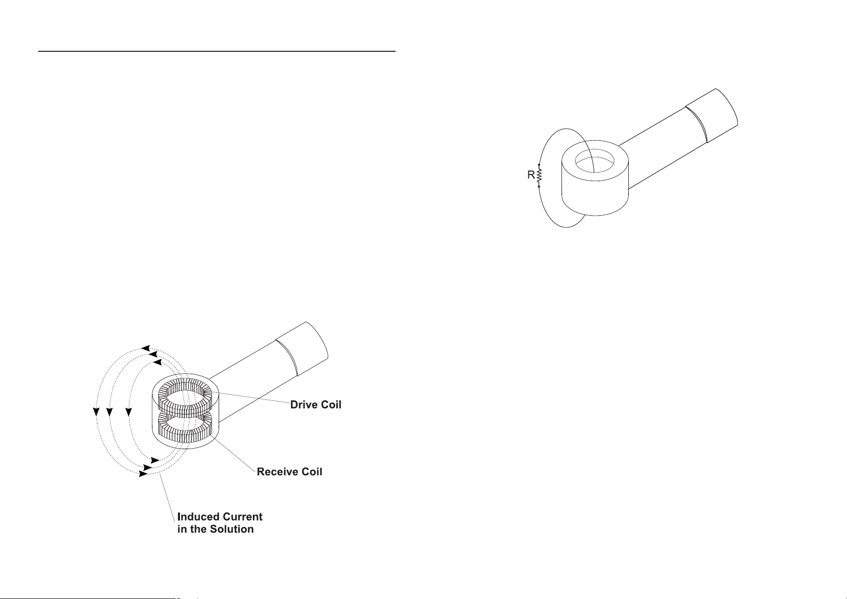
The measurement is based on inductive coupling of two toroidal transformers by
the liquid.
The instrument supplies a high frequency, reference voltage to the “Drive Coil”,
and a strong magnetic field is generated in the toroid.
The liquid passes through the hole in the toroid and can be considered as oneturn secondary winding. The magnetic field induces a voltage in this liquid winding, the current induced in the flow is proportional to this voltage, and the conductance of the liquid one-turn winding is according to the Ohm’s law.
The conductance is proportional to the specific conductivity and a constant factor determined by the sensor geometry and installation.
The liquid also passes through the second toroid and therefore the liquid turn
can be considered as a primary winding of the second toroidal transformer. The
current in the liquid will create a magnetic field in the second toroid, and the
induced current can be measured as an output.
The output current of this “Receive Coil” is therefore proportional to the specific
conductivity of process liquid.
For an inductive cell, the cell constant is defined as the measured conductivity,
obtained by making a loop through the sensor with a resistor R, multiplied by
that R value.
The cell constant depends only on the sensor geometry. However, when the probe
is immersed in a liquid, the induced current in the solution is affected by the
piping or any other container where the probe is inserted. This effect is negligible
when there is an area of at list 3 cm of liquid around the cell.
Otherwise, it is necessary to multiply measurements by the installation factor:
Conductivity = (cell constant)(installation factor)/(measured resistance)
The installation factor is < 1 for conductive piping/containers, and > 1 for nonconductive piping/containers.
Since this type of sensor has no electrodes, common problems due to the electrode contact, such as polarization and contamination, will not affect the performance of our electrodeless sensor.
The probe working life is extremely long and the sensor maintenance will be an
exceptional operation.
The controllers are equipped with a graphic display, easy to understand as your
cellular phone. Simple messages guide the users through all operations and
parameter setting.
6
7
Page 5

The main features of the HI 720 controller series include:
• Measurement and control of conductivity or concentration
• Concentration can be measured as usual TDS (fixed ratio) or through custom
conductivity/temperature/concentration curves
• Customizing temperature coefficient table and NaCl temperature compensation according to IEC 746-3, in addition to the standard linear compensation
• Auto-ranging
• Display reading offset adjustment for temperature
• Temperature level alarm
• Cleaning in place activated through two cleaning commands, or triggered by
a variety of events
• Hold management, including a digital input to enter the hold mode through
an external trigger
• Conductivity probe check
• Digital transmitter input
• Pt100 or Pt1000 temperature sensor with automatic recognition and damage test
• Calibration time-out
• Logging of the last 100 error, configuration and cleaning events
• Alarm fault current (3.6 mA or 22 mA)
• SMS messages sending
• Alarm configuration can be customized: different errors can lead different
actions (alarm relay activation, fault current, hold mode, automatic cleaning,
SMS message)
• RS485 communication with additional capabilities, such as error log file downloading and cleaning commands
• Daily programmable control timing
• Diagnostic features
• Password protection
SPECIFICATIONS
Range 0 to 2000 mS/cm (auto-ranging)
-30 to 130°C / -22 to 266°F
Resolution 1 μS/cm (0 to 1999 μS/cm)
0.01 mS/cm (2.00 to 19.99 mS/cm)
0.1 mS/cm (20.0 to 199.9 mS/cm)
1 mS/cm (200 to 2000 mS/cm)
0.1°C / 0.2°F
Accuracy ±2% f.s. (conductivity) / ±0.5°C / ±1°F
Typical EMC Deviation ±2% f.s. (conductivity) / ±0.5°C / ±1°F
Temp. Compensation Automatic or manual, -30 to 130°C
Temperature Probe 3-wire or 2-wire Pt100 or Pt1000 sensor
with automatic recognition and damage test
Digital Input Digital Transmitter, Hold & Advanced Cleaning inputs
Digital Output 1 digital insulated contact closed upon Hold mode
Analog Output 1 or 2 independent outputs;
0-22 mA (configuring as 0-20 mA or 4-20 mA)
Digital Serial Output RS485
Dosing Relay 1, 2, 3 or 4 electromechanical relays SPDT;
5A-250 Vac, 5A-30 Vdc (resistive load);
fuse protected: 5A, 250 V fuse
Alarm Relay 1 electromechanical relay SPDT;
5A-250 Vac, 5A-30 Vdc (resistive load);
fuse protected: 5A, 250 V fuse
Installation Category II
Power Supply 24 Vdc/ac, or
115 Vac or 230 Vac or 100 Vac ±10%, 50/60 Hz;
fuse protected: 400 mA, 250 V fast fuse
Power Consumption 10 VA
Max Oscillation Frequency 8 MHz
Environment 0 to 50°C (32 to 122°F); RH max 85% non-condensing
Enclosure Single case 1/2 DIN
Weight Approx. 1.6 kg (3.5 lb.)
8
9
Page 6
FUNCTIONAL DESCRIPTION
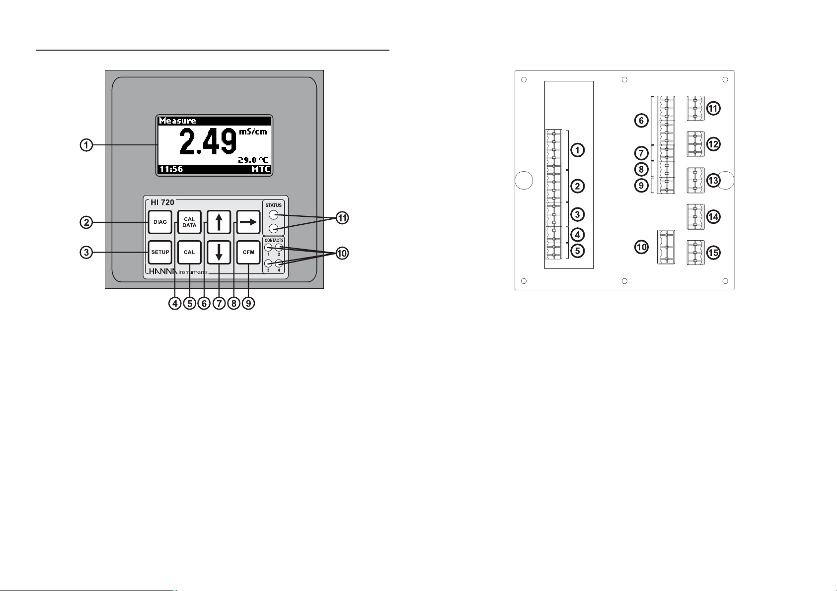
1. Graphic display (128 x 64 dots)
2. DIAG key, to enter/exit diagnostic mode; to change the conductivity or
concentration range while in setup or calibration mode
3. SETUP key, to enter/exit setup mode
4. CAL DATA key, to enter/exit last calibration data viewing mode
5. CAL key, to enter/exit calibration mode
6. key, to increase current digit by 1, shift to next option, or move to next
record while in diagnostic mode
7. key, to decrease current digit by 1, shift to previous option, or move to
previous record while in diagnostic mode
8. key, to cyclically change temperature compensation option for conductivity readings: compensation enabled (temperature is continuously displayed) or compensation disabled (actual reading). Only displayed values
are affected by this key; control and logging are not affected.
9. CFM key, to confirm current choice
10. Contact LEDs, each turns on when the corresponding relay is energized
11. Status (red) and alarm (green) LEDs
10
1. Connections for conductivity probe
2. Connections for Pt100/Pt1000 temperature sensor
3. Digital Transmitter input
4. Hold input
5. Advanced Cleaning input (optional)
6. RS485 output terminal
7. Hold output
8. Analog output #1
9. Analog output #2 (optional)
10. Power supply input
11. Relay #3 - for Advanced Cleaning feature (optional)
12. Relay #4 - for Advanced Cleaning feature (optional)
13. Relay #1 - first dosing terminal
14. Relay #2 - second dosing terminal (optional)
15. Alarm relay
11
Page 7
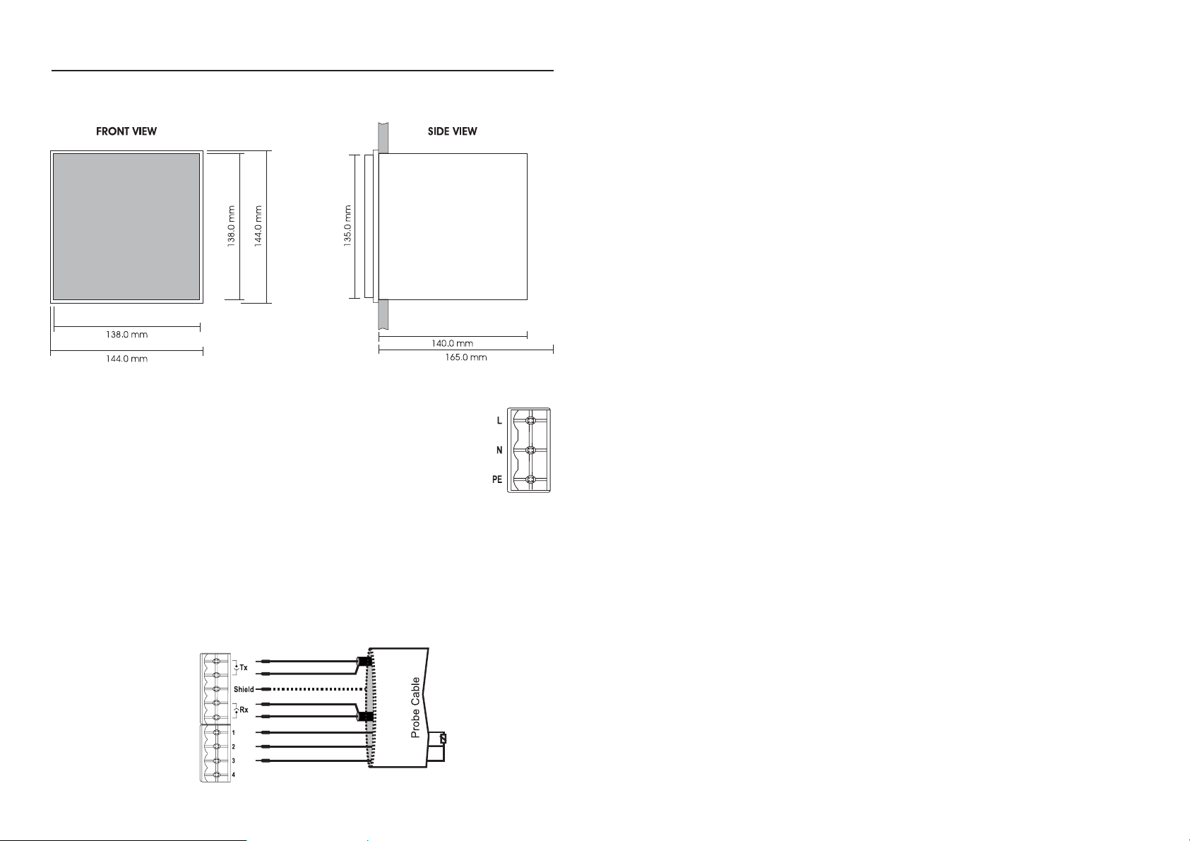
INSTALLATION
Mechanical Dimensions
Electrical Connections
• Power Input: connect a 3-wire power cable to the line (L), earth
(PE) and neutral (N) terminal connections.
Power: 100 Vac-120 mA / 115 Vac-100 mA / 230 Vac-50 mA.
Line Contact: 400 mA fuse inside.
PE must be connected to ground; leakage current 1 mA.
•
Probe Connections (#1 at page 9): connect the Tx and Rx coaxial cables to
the relevant terminals, as indicated. Connect the probe cable shield to the
“Shield” terminal.
• Pt100/Pt1000 Terminals (#2 at page 9): these contacts connect the Pt100/
Pt1000 sensor for automatic temperature compensation.
If the conductivity probe features a built-in Pt100/Pt1000 sensor, connect the
related wires to pins 1, 2 and 3; pin 4 will not be used.
It is also possible to use a separate Pt100/Pt1000 temperature probe. In the
case of shielded wire, connect the shield to pin 4. In the case of a 2-wire
sensor connect the Pt100/Pt1000 to pins 1 and 3, and short pins 2 and 3
with a jumper wire.
If the Pt100/Pt1000 probe has more than 2 wires, connect the two wires of
one end to pins 2 and 3 (pin 2 is an auxiliary input to compensate for the
cable resistance) and one wire from the other end to pin 1. Leave the fourth
wire unconnected, if present.
Note The instrument automatically recognizes the sensor type (Pt100 or
Pt1000).
• Analog Outputs: when using shielded cable, if the shield is not connected at
the other end of the cable, then connect it to the “+” terminal, otherwise
leave it floating.
Note All cables connected to rear panel should end with cable lugs.
Note A circuit breaker (rated 10 A max.) must be connected in close prox-
imity to the equipment, and in a position easy to reach by the operator, for disconnection of the instrument and all devices connected to
the relays.
12
13
Page 8
OPERATIONAL GUIDE
The HI 720 process controller can operate in six main modes:
• Setup mode
• Calibration mode
• Control mode
• Idle mode
• Last calibration data viewing mode
• Diagnostic mode (active errors & event log file scrolling)
All operating modes are described in the following sections.
SETUP MODE
The Setup mode allows the user to set all needed characteristics of the meter. To
enter the mode, press the SETUP key and enter the password when the device is
in idle or control mode.
If the correct password is not entered, the user can view the setup parameters
(except passwords, phone numbers and PIN code), but not modify them (and
the device remains in control mode).
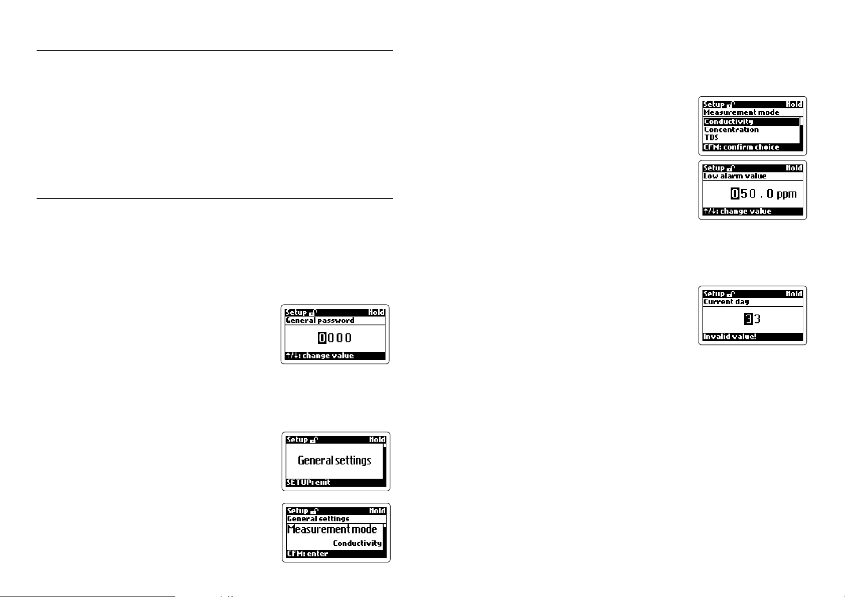
Entering the Password
• Press the SETUP key to enter the setup mode.
The display will show “0000” (default value),
with the first digit highlighted.
• Enter the first digit of the password by using the
up & down arrow keys.
• Move to the next digit with the key and enter the desired value as described
above. Continue for the last two digits. When the whole password has been
inserted, press CFM to confirm.
Entering Setup Items
• After the password has been confirmed, the dis-
play will show the name of the first setup group
(General Setting).
• Using the arrow keys it is possible to cycle
through all setup groups, while pressing SETUP
will exit the mode, and pressing CFM will con-
firm the desired selection.
• Once a group is selected, the display shows the
first parameter of the group together with its
current value.
14
The user can choose the desired parameter with the up & down arrow keys,
and confirm the selection by pressing CFM.
Note For some groups, it is necessary to enter several sublevels before
choosing a parameter value. Follow the displayed messages to proceed, confirm or exit each screen.
• If a fixed set of values is available for the selected item, use the arrow keys to switch between them. Otherwise, if a numeric value has
to be entered, use the arrow keys to change the
value of the highlighted digit and cycle through
the number’s digits.
• Once a value is set, press the CFM key to confirm, and the instrument will turn to the previous screen.
Note After modifying a value in the concentration curve triplets or in
the conductivity/temperature couples for the temperature com-
pensation algorithm, then it is not possible to exit without saving. To
return to the previous value, the number must be entered again.
• If a wrong value is confirmed, the “Invalid value!”
or “Invalid choice!” message advises the user,
the value is not accepted and the instrument
will not switch to the next item until a correct
value will be confirmed.
• When the last item of the group is reached, by pressing the CFM key again the
display will show the group name. The group can then be changed by pressing the up & down arrow keys.
Note If no activity is performed for about 5 minutes after entering the
setup mode, the mode is automatically exited and the instrument
returns to the previous mode.
15
Page 9

This table lists all available setup items together with their code, short description, valid values and default setting.
Setup Item Description Valid Values Default
GENERAL SETTINGS
G.00 Measurement mode Conductivity, Conductivity
(see note 8) Concentration, TDS
G.01 Conductivity range Auto range, Auto range
1999 μS/cm,
19.99 mS/cm,
199.9 mS/cm,
2000 mS/cm
G.02 TDS range Auto range, Auto range
1000 ppm, 10.00 ppt,
100.0 ppt, 1000 ppt
G.03 Concentration unit Auto (ppm/ppt), Auto
(see note 31) ppm, ppt, % (ppm/ppt)
G.04 Concentration XXXX, XXX.x, XX.xx
format XX.xx, X.xxx
G.05 TDS factor 0.00 to 1.00 0.50
G.06 Moving average 1 to 30 1
length (see note 30)
G.10 Factory ID 0000 to 9999 0000
G.11 Process ID alias 00 to 99 00
RS485 address
G.13 Language English, Italiano English
G.14 LCD contrast 0 to 10 6
G.15 LCD backlight On, Off On
G.98 Calibration 0000 to 9999 0000
password (see note 2)
G.99 General password 0000 to 9999 0000
(see note 2)
TEMPERATURE
b.01 Compensation mode Automatic (ATC), ATC
(see notes 7, 20) Manual (MTC)
b.02 Start manual temp. -30.0 to 130.0°C 25.0°C
(see notes 7, 20)
Setup Item Description Valid Values Default
TEMPERATURE
b.03 Temperature measure °C, °F °C
unit (see note 32)
b.10 Temp. compensation Linear, Linear
algorithm (note 28) NaCl
(IEC 746, table BII),
User: user defined table
b.11 Reference temp. 20°C, 25°C 25°C
(see note 28)
b.12 Temp. coefficient 0.00 to 20.00 % 2.00 %
(see notes 28, 29)
Temperature Compensation Table
b.31 Number of couples 2 to 10 2
b.32 Edit/view couple 1 to b.31 item value 1
b.33 User table: actual 0 to f.s. see note 33
conductivity value for
the couple selected in b.32
b.34 User table: -30.0 to 130.0°C see note 33
temperature value for
the couple selected in b.32
Temperature Level Alarm (see Note 36)
b.41 Max temperature -30.0 to 130.0°C 130.0°C
b.42 Min temperature -30.0 to 130.0°C -30.0°C
Reading Offset
b.50 Actual reading measurement -10.0°C measurement
(for ATC only, to measurement +10°C (see note 15)
see notes 15, 20)
b.51 Temperature offset -10.0°C to +10.0°C 0.0°C
(ATC only, notes 15, 20)
CONCENTRATION
d.00 Concentration curve 1 to 4 1
in use
Curve 1/2/3/4 Table (see note 34)
d.01 Number of triplets 1 to 25 1
d.02 Edit/view triplet 1 to d.01 value 1
16
17
Page 10

Setup Item Description Valid Values Default
Curve 1/2/3/4 Table (see note 34)
d.03 Not compensated 0 to f.s. 0 μS/cm
conductivity value for
the triplet selected in d.02
d.04 Temperature value for -30.0 to 130.0°C 0.0°C
the d.02 triplet
d..05 Concentration value 0 to f.s 0 ppm
for the d.02 triplet
CONTROL
C.00 Control enable On, Off Off
Setpoint 1
C.10 Setpoint 1 mode Disabled, On/Off low
(M1) On/Off high,
(see note 1) On/Off low,
PID high (if available),
PID low (if available)
C.11 Setpoint 1 value 0 to f.s. 500 μS/cm
(S1) (see note 1)
C.12 Setpoint 1 0 to f.s. 20 μS/cm
hysteresis (H1) (see note 1)
C.13 Setpoint 1 Up to f.s and ≠0 20 μS/cm
deviation (D1) (see note 1)
C.14 Setpoint 1 reset time 0.1 to 999.9 minutes 999.9 min.
C.15 Setpoint 1 rate time 0.0 to 999.9 minutes 0.0 min.
Setpoint 2
C.20 Setpoint 2 mode Disabled, On/Off low
(M2) On/Off high,
(see note 1) On/off low,
PID high (if available),
PID low (if available)
C.21 Setpoint 2 value 0 to f.s. 1500 μS/cm
(S2) (see note 1)
C.22 Setpoint 2 0 to f.s. 20 μS/cm
hysteresis (H2) (see note 1)
C.23 Setpoint 2 Up to f.s and ≠0 20 μS/cm
deviation (D2) (see note 1)
18
Setup Item Description Valid Values Default
Setpoint 2
C.24 Setpoint 2 reset time 0.1 to 999.9 minutes 999.9 min.
C.25 Setpoint 2 rate time 0.0 to 999.9 minutes 0.0 min.
Alarms
C.30 Low alarm value 0 to f.s 100 μS/cm
(LA) (see note 18) (see note 1)
C.31 High alarm value 0 to f.s 1900 μS/cm
(HA) (see note 18) (see note 1)
C.32 Max relay ON time 1 to 60 minutes 60 min.
(then an alarm is generated)
C.33 Alarm mask time 00:00 to 30:00 min. 00:30
(see notes 18, 27)
C.34 Alarm hysteresis 0 to f.s. 20 μS/cm
(AH) (see note 18)
Programmable Control
C.41 Hold time start (note 6) 00:00 to 23:59 00:00
C.42 Hold time stop (note 6) 00:00 to 23:59 00:00
C.51 Monday hold mode Off: disabled, Off
On: enabled
C.52 Tuesday hold mode Off: disabled, Off
On: enabled
C.53 Wednesday hold Off: disabled, Off
mode On: enabled
C.54 Thursday hold Off: disabled, Off
mode On: enabled
C.55 Friday hold mode Off: disabled, Off
On: enabled
C.56 Saturday hold mode Off: disabled, Off
On: enabled
C.57 Sunday hold mode Off: disabled, Off
On: enabled
Other Parameters
C.60 Proportional control 01:00 to 30:00 min. 05:00 min.
period (if available)
19
Page 11

Setup Item Description Valid Values Default
Other Parameters
C.70 Hold mode end delay 00 to 99 seconds 00 sec
C.80 On/Off control 00:00 to 30:00 min. 00:00 min
action delay (note 26)
OUTPUT
Relays
O.01 Relay 1 mode Disabled, Control-
(see notes 16, 17) Control-setpoint 1, setpoint 1
Control-setpoint 2,
Simple cleaning,
Hold mode
O.02 Relay 2 mode Disabled, Control-
(see notes 16, 17) Control-setpoint 1, setpoint 2
Control-setpoint 2,
Simple cleaning,
Hold mode
O.03 Relay 3 mode Disabled, Disabled
(see notes 12, 16) Simple cleaning,
Advanced cleaning,
Hold mode
O.04 Relay 4 mode Disabled, Disabled
(see notes 12, 16) Simple cleaning,
Advanced cleaning,
Hold mode
O.05 Hold digital output Disabled or Hold mode
Hold mode
Analog Output 1
O.10 Analog output 1 Recorder or Recorder
mode (notes 1, 17) Control-setpoint 1
O.11 Analog output 1 0-20 mA or 4-20 mA
type 4-20 mA
O.12 Analog output 1 0 to f.s. 0 μS/cm
minimum value (O_VARMIN1 ≤
(O_VARMIN1) O_VARMAX1 -5% f.s. for
O_VARMAX1, O_VARMIN1
≤ O_HOLD1 ≤ O_VARMAX1)
Setup Item Description Valid Values Default
Analog Output 1
O.13 Analog output 1 0 to f.s. 1999 μS/cm
maximum value (O_VARMIN1 ≤
(O_VARMAX1) O_VARMAX1 -5% f.s. for
O_VARMAX1, O_VARMIN1
≤ O_HOLD1 ≤ O_VARMAX1)
O.14 Analog output 1 User selected value, Previous value
hold mode (note 13) Previous value
O.15 Analog output 1 0 to f.s. 1000 μS/cm
hold mode value (it must be within the
(O_HOLD1) O_VARMIN1 to
O_VARMAX1 interval)
Analog Output 2
O.20 Analog output 2 Recorder (temperature), Recorder
mode (notes 1, 17) Control-setpoint 2
(conductivity/concentration
/temperature)
O.21 Analog output 2 0-20 mA or 4-20 mA
type 4-20 mA
O.22 Analog output 2 -30.0 to 130.0°C 0.0°C
minimum value (O_VARMIN2 ≤
(O_VARMIN2) O_VARMAX2 -10°C,
O_VARMIN2 ≤ O_HOLD2
≤ O_VARMAX2)
O.23 Analog output 2 -30.0 to 130.0°C 100.0°C
maximum value (O_VARMIN2 ≤
(O_VARMAX2) O_VARMAX2 -10°C,
O_VARMIN2 ≤ O_HOLD2
≤ O_VARMAX2)
O.24 Analog output 2 User selected value, Previous value
hold mode (note 13) Previous value
O.25 Analog output 2 -30.0 to 130.0°C 25.0°C
hold mode value (it must be within the
(O_HOLD2) O_VARMIN2 to
O_VARMAX2 interval)
20
21
Page 12

Setup Item Description Valid Values Default
INPUT
I.00 Input selection Inductive probe or Inductive
(note 10) Digital transmitter probe
I.03 Digital transmitter 00 to 99 00
address (active if I.00=Digital transmitter)
I.04 Digital transmitter 1200, 2400, 4800, 19200 bps
baud rate 9600 or 19200 bps
I.10 Calibration timeout 0 to 12 months 12 months
I.11 Life check Disabled, Disabled
(see notes 9, 20) 1 hour, 2 hours,
or 4 hours
REAL TIME CLOCK (see Note 4)
r.00 Current day 01 to 31 from RTC
r.01 Current month 01 to 12 from RTC
r.02 Current year 2000 to 2099 from RTC
r.03 Current time 00:00 to 23:59 from RTC
COMMUNICATION
P.00 Connection type PC, PC
HI 504900 GSM module,
HI 504901 GSM supervisor,
HI 504902 Modem
P.01 Baud rate 1200, 2400, 4800, 19200 bps
9600 or 19200 bps
P.02 Call answer enable On, Off Off
P.03 Modem country Insert the phone 000
code country code for the
HI 504902 modem
(see note 35)
P.11 PIN code 0000 to 9999 0000
P.12 Phone number #1 + --------------------
(see note 21) (“Not set” means no number entered)
P.13 Phone number #2 + --------------------
(see note 21) (“Not set” means no number entered)
Setup Item Description Valid Values Default
COMMUNICATION
P.14 Remaining SMS 000 to 200, or 222 100
(see note 22)
P.15 Repeated SMS 0 to 5 (see note 23) 2
P.16 SMS delay between 05 to 60 minutes 10 minutes
messages (see note 24)
P.17 SIM card expiration 01 to 31 01
day (see note 25)
P.18 SIM card expiration 01 to 31 01
month (see note 25)
P.19 SIM card expiration 2000 to 2099 2010
year (see note 25)
CLEANING
Simple Cleaning
L.00 Rinsing time 5 to 99 seconds 20 seconds
L.01 Pause time 10 to 9999 minutes 1440 min.
Advanced Cleaning (see Note 19)
L.10 Pre-rinsing time 0 to 99 seconds 20 seconds
L.11 Cleaning time 0 to 99 seconds 10 seconds
L.12 Rinsing time 5 to 99 seconds 20 seconds
L.13 Pause time 10 to 9999 minutes 1440 min.
L.14 Minimum pause time 10 to L.13 minutes 10 minutes
L.15 Cleaning trigger Timer only, Timer only
External only,
Timer and external,
Timer masked by external
L.16 Repeated cycles no. 0 to 10 0
L.17 Economy cycle no. 0 to 10 0
ERROR CONFIGURATION (see Note 5)
E.00 High alarm (00) Alarm relay -------------> On
22 mA fault current----> On
3.6 mA fault current---> Off
Auto cleaning ----------> Off
SMS sending -----------> Off
22
23
Page 13

Setup Item Description Valid Values Default
ERROR CONFIGURATION
E.01 Low alarm (01) Alarm relay -------------> On
22 mA fault current----> Off
3.6 mA fault current---> On
Auto cleaning ----------> Off
SMS sending -----------> Off
E.02 Max relay ON time Alarm relay -------------> On
error (02) 22 mA fault current----> On
3.6 mA fault current---> Off
Auto cleaning ----------> Off
SMS sending -----------> Off
E.03 Life check error (03) Alarm relay -------------> On
(see note 9) 22 mA fault current----> On
3.6 mA fault current---> Off
Hold mode --------------> On
Auto cleaning ----------> Off
SMS sending -----------> Off
E.10 Conductivity input Alarm relay -------------> On
overflow (10) 22 mA fault current----> On
3.6 mA fault current---> Off
Hold mode --------------> Off
Auto cleaning ----------> Off
SMS sending -----------> Off
E.12 Calibration timeout Alarm relay -------------> Off
(12) 22 mA fault current----> Off
3.6 mA fault current---> Off
SMS sending -----------> Off
E.20 Broken temperature Alarm relay -------------> On
probe (20) 22 mA fault current----> On
3.6 mA fault current---> Off
Hold mode --------------> Off
SMS sending -----------> Off
Setup Item Description Valid Values Default
ERROR CONFIGURATION
E.21 Temperature level Alarm relay -------------> On
error (21) 22 mA fault current----> On
3.6 mA fault current---> Off
SMS sending -----------> Off
E.40 Digital transmitter Alarm relay -------------> On
error (40) 22 mA fault current----> On
3.6 mA fault current---> Off
Hold mode --------------> On
SMS sending -----------> Off
E.50 GSM/Modem Alarm relay -------------> On
module error (50) 22 mA fault current----> On
3.6 mA fault current---> Off
E.60 Temp. compensation Alarm relay -------------> On
error (60) 22 mA fault current----> On
3.6 mA fault current---> Off
SMS sending -----------> Off
E.61 Temperature out of Alarm relay -------------> On
concentration table 22 mA fault current----> On
(61) 3.6 mA fault current---> Off
SMS sending -----------> Off
E.62 Conductivity out of Alarm relay -------------> On
concentration table 22 mA fault current----> On
(62) 3.6 mA fault current---> Off
Auto-cleaning ----------> Off
SMS sending -----------> Off
E.63 Concentration out Alarm relay -------------> On
of user concentration 22 mA fault current----> On
table (63) 3.6 mA fault current---> Off
SMS sending -----------> Off
E.90 Power reset (90) Alarm relay -------------> Off
22 mA fault current----> On
3.6 mA fault current---> Off
SMS sending -----------> Off
24
25
Page 14

Setup Item Description Valid Values Default
ERROR CONFIGURATION
E.91 EEPROM corruption Alarm relay -------------> On
(91) 22 mA fault current----> On
3.6 mA fault current---> Off
SMS sending -----------> Off
E.92 Watchdog error Alarm relay -------------> Off
(92) 22 mA fault current----> On
3.6 mA fault current---> Off
SMS sending -----------> Off
E.99 Level or pulse signal Level or Pulse Level
(note 11)
TEST
t.00 Display test
t.01 Keyboard test
t.02 EEPROM test
t.03 Relays and LEDs test
t.04 Analog output 1 test
t.05 Analog output 2 test
t.06 Hold digital input test
t.07 Advanced cleaning digital input test
(WARNING: cleaning actions can
be triggered by this input going high
during the test. See note 19 for details)
NOTES:
(1) M1 can not be set to “On/Off high” or “On/Off low” if O.10 is set to
“Control-setpoint 1” and vice versa.
0 ≤ LA + AH < HA - AH ≤ f.s.
if M1 = “PID high”, then S1 + D1 ≤ HA - AH
if M1 = “PID low”, then S1 - D1 ≥ LA + AH
if M1 = “On/Off high”, then S1 - H1 ≥ LA + AH
if M1 = “On/Off low”, then S1 + H1 ≤ HA - AH
M2 can not be set to “On/Off high” or “On/Off low” if O.20 is set to
“Control-setpoint 2” and vice versa.
if M2 = “PID high”, then S2 + D2 ≤ HA - AH
if M2 = “PID low”, then S2 - D2 ≥ LA + AH
if M2 = “On/Off high”, then S2 - H2 ≥ LA + AH
if M2 = “On/Off low”, then S2 + H2 ≤ HA - AH
if M1 = “On/Off high” and M2 = “On/Off low”, then S1 - H1 ≥ S2 + H2
if M1 = “On/Off low” and M2 = “On/Off high”, then S2 - H2 ≥ S1 + H1
if M1 = “PID high” and M2 = “On/Off low”, then S1 ≥ S2 + H2
if M1 = “On/Off low” and M2 = “PID high”, then S1 + H1 ≤ S2
if M1 = “PID low” and M2 = “On/Off high”, then S1 ≤ S2 - H2
if M1 = “On/Off high” and M2 = “PID low”, then S1 - H1 ≥ S2
if M1 = “PID high” and M2 = “PID low”, then S1 ≥ S2
if M1 = “PID low” and M2 = “PID high”, then S2 ≥ S1
In addition to the above constraints, in any case, unless M1 = “Off”, it must be
LA + AH ≤ S1 ≤ HA - AH , and, unless M2 = “Off”, it must be LA + AH ≤ S2
≤ HA - AH. Deviation must be ≠0.
“f.s.” (full scale) is the maximum displayed value for the currently configured type
of measurement, range and unit.
Setup codes are never displayed by the controller, but they are used to
identify each setup item in this instruction manual, and for the RS485
communication protocol (see “Communication” section).
26
(2) The calibration password allows calibration and hold mode through the
keyboard for service personnel only, while the general password allows any operation (including calibration). Obviously, the general and the calibration/hold
passwords can not be viewed among other items when the SETUP key is pressed
without entering the right general password. The default general password is
“0000”. If the user forgets the general password, this can be reset to the default
value by pressing CFM+DIAG+CAL DATA simultaneously, while in normal operating mode (idle or control mode). Confirmation is required for the reset; press
the up arrow key to confirm the choice.
27
Page 15

(3) When a wrong setup code or value is confirmed, the controller does not
move from the current window, and displays a blinking WRONG message till the
user changes the value. Note that the allowed values for some parameters depend from other settings (e.g. to set a high setpoint to 10.00 mS, first set the
high alarm to a value greater than 10.00 mS).
(4) Each time the controller is powered, the RTC is checked to detect if an RTC
reset occurred since last software initialization. If that happened, the RTC is initialized with the default date and time (01-01-2000 ; 00:00).
An EEPROM reset does not affect the RTC settings.
(5) The error configuration value is always displayed together with each error
configuration item, and is coded as shown on this table
Error Alarm 22 mA 3.6 mA Hold Auto- SMS
Config. Relay fault curr. fault curr. mode cleaning sending
00 OFF OFF OFF OFF OFF OFF
01 ON OFF OFF OFF OFF OFF
02 OFF ON OFF OFF OFF OFF
03 ON ON OFF OFF OFF OFF
04 OFF OFF ON OFF OFF OFF
05 ON OFF ON OFF OFF OFF
06 OFF OFF OFF ON OFF OFF
07 ON OFF OFF ON OFF OFF
08 OFF ON OFF ON OFF OFF
09 ON ON OFF ON OFF OFF
10 OFF OFF ON ON OFF OFF
11 ON OFF ON ON OFF OFF
12 OFF OFF OFF OFF ON OFF
13 ON OFF OFF OFF ON OFF
14 OFF ON OFF OFF ON OFF
15 ON ON OFF OFF ON OFF
16 OFF OFF ON OFF ON OFF
17 ON OFF ON OFF ON OFF
18 OFF OFF OFF ON ON OFF
19 ON OFF OFF ON ON OFF
20 OFF ON OFF ON ON OFF
21 ON ON OFF ON ON OFF
Error Alarm 22 mA 3.6 mA Hold Auto- SMS
Config. Relay fault curr. fault curr. mode cleaning sending
22 OFF OFF ON ON ON OFF
23 ON OFF ON ON ON OFF
24 OFF OFF OFF OFF OFF ON
25 ON OFF OFF OFF OFF ON
26 OFF ON OFF OFF OFF ON
27 ON ON OFF OFF OFF ON
28 OFF OFF ON OFF OFF ON
29 ON OFF ON OFF OFF ON
30 OFF OFF OFF ON OFF ON
31 ON OFF OFF ON OFF ON
32 OFF ON OFF ON OFF ON
33 ON ON OFF ON OFF ON
34 OFF OFF ON ON OFF ON
35 ON OFF ON ON OFF ON
36 OFF OFF OFF OFF ON ON
37 ON OFF OFF OFF ON ON
38 OFF ON OFF OFF ON ON
39 ON ON OFF OFF ON ON
40 OFF OFF ON OFF ON ON
41 ON OFF ON OFF ON ON
42 OFF OFF OFF ON ON ON
43 ON OFF OFF ON ON ON
44 OFF ON OFF ON ON ON
45 ON ON OFF ON ON ON
46 OFF OFF ON ON ON ON
47 ON OFF ON ON ON ON
Note that the values in this table are used for error configuration through RS485.
(6) The hold mode is never enabled by the control timing if the “hold time
start” is the same as the “hold time end”. Items C.41 and C.42 apply to all days.
The hold mode can be enabled all day long by using items C.51 to C.57.
(7) See “Temperature Compensation” section for more details about Automatic and Manual temperature compensation functioning.
(8) Whenever the measurement type (G.00) is changed, all conductivity and
28
29
Page 16

TDS values in setup (excluding the temperature compensation table and the concentration curves) are automatically updated, so that the “new value / new f.s.”
= “previous value / previous f.s.“
(9) A life check error is generated if the reading does not vary more than 0.5%
of the current f.s. within the time period selected through the “life check time”
setup item.
(10) When a Digital Transmitter is used, temperature and conductivity are measured by the transmitter, and sent to the process controller. The calibration data
set for the digital transmitter is separated from the one regarding the inductive
probe input. This means that the calibration data is automatically switched from
inductive probe set to digital transmitter set, and vice versa, each time the measurement input is changed from “Inductive probe” to “Digital transmitter”, and
vice versa. For example, if measurements are performed with an inductive probe
directly connected to the controller, then through a transmitter, and again with
the direct probe, it is not necessary to re-calibrate the conductivity input.
(11) The alarm relay can be energized continuously (by selecting “Level” option)
or with a pulse (by selecting “Pulse” option). The pulse span is fixed at approximately 5 seconds.
(12) Both relays 3 and 4 must be set to “Advanced cleaning” for enabling the
advanced cleaning feature. If only one of them is set to “Advanced cleaning”, it
will behave as if it were set to “Off”. Once the advanced cleaning is enabled,
relay 3 is used for water pouring and relay 4 for detergent pouring.
(13) “Previous value” and “User selected value” are effective only when items
O.10 and O.20 are set to “Recorder”, otherwise the analog output is automatically set to the minimum value upon hold mode (i.e. items O.14 & O.15, O.24
& O.25 have no effect if O.10 = Control-setpoint 1 and O.20 = Controlsetpoint 2, respectively).
(14) “Measured value” is the reading with no reading offset adjustment.
(15) If the device is set for MTC, items b.50 and b.51 can not be modified nor
viewed. When setup item b.01 is changed from ATC to MTC, item b.11 is automatically zeroed.
(17) If the relay 1 (or relay 2) mode is set to “Control-setpoint 1”, the analog
output 1 can not be set to “Control-setpoint 1”, and vice versa. Similarly, if the
relay 1 (or relay 2) mode is set to “Control-setpoint 2”, the analog output 2 can
not be set to “Control-setpoint 2”, and vice versa.
(18) The alarm turns off only when the alarm hysteresis (setup item C.34) has
been passed. For high alarm, the alarm turns off below “high alarm - hysteresis”,
while for low alarm, the alarm turns off above “low alarm + hysteresis”).
(19) The actual start of a cleaning action depends on the configuration of relay
3, relay 4 and advanced cleaning parameters.
(20) When using the digital transmitter, this item is not visible, and the corresponding digital transmitter setting is used.
(21) An SMS will be sent to this telephone number when an error configured for
SMS sending, occurs. No SMS will be sent if no number has been entered.
(22) This item states the maximum number of SMSs that the meter can send.
Before this number reaches 0, a warning message will be sent to the programmed
telephone numbers (items P.12 and P.13). This function has been introduced for
avoiding the discharge of the SIM card credit. Once all available messages have
been sent, the user should extract the SIM card from the GSM module and
check remaining credit and expiration date.
The item always shows the remaining number of SMSs. This value is obviously
decremented at each SMS submission.
If this item is set to “222”, no check will be done and the instrument can send an
unlimited number of messages. The item value will not be decremented upon
SMS sending, and the SIM expiration date will not be checked.
(23) Each SMS sent by the instrument requires a confirmation phone call. If this
confirmation does not arrive, it is possible to set the instrument for repeated
message sending. The maximum number of repeated messages is set through
this setup item, while the delay between to subsequent messages is set through
the item P.16. If the repeated message number is set to 0, then no receiving
confirmation is needed.
(24) The delay between two subsequent messages acts only if P.15 ≠ 0.
(16) When relays set to “Simple cleaning” are all changed to another option,
the simple cleaning action in progress, is aborted immediately. When relay 3,
relay 4 or both of them are set to an option different from “Advanced cleaning”,
the cleaning action in progress, is aborted immediately, but a complete rinsing is
always performed before the actual end of the advanced cleaning session.
30
(25) The SIM expiration date has to be entered manually through items P.17 to
P.19. The user should update these values at each card recharge. Three warning
messages are sent to the programmed telephone numbers (items P.12 and P.13)
to advise the user that the card is expiring (two weeks before, one week before
and one day before the expiration date).
31
Page 17

If the item P.14 has been set to “222”, no expiration date check will be done.
(26) This item is particularly useful in noisy environment, to filter measurement
spikes and avoid undesired activations of the on/off control contacts. The relay
energizes and de-energizes only if the corresponding threshold is overridden for
more than the configured contact action delay (see below graph: “dly” is the
contact action delay; relays are energized and de-energized at times t
+dly).
n
(30) This parameter set the number of latest measurements used to calculate
an average value. The average is calculated both for conductivity/concentration
and temperature. The averaged conductivity/concentration value is then used
both for displaying and control.
(31) When the concentration unit is changed, all items from C.00 to C.34 and
from O.12 to O.15 are reset to the default values.
(32) The degree Fahrenheit unit is used only for displaying the temperature
while in normal measurement mode.
(33) The default values for the temperature compensation table are:
Couple Actual Conductivity Temperature
1 500 μS/cm 0.0 °C
2 600 μS/cm 5.0 °C
3 700 μS/cm 10.0 °C
4 800 μS/cm 15.0 °C
5 900 μS/cm 20.0 °C
(27) The alarm mask time specifies for how long the conductivity/concentration/temperature value must remain outside the alarm thresholds before an alarm
is actually generated. Note that the conductivity/concentration/temperature value
must return within the alarm thresholds and remain stable for the same time,
before the device can close the alarm.
(28) The linear temperature compensation is performed according to the
following formula:
Compensated conductivity = Actual conductivity / [1+β(T-Tref)/100]
where T is the measured temperature
and Tref is the reference temperature (20 or 25°C).
The temperature coefficient must be manually adjusted by the user when chang-
ing the reference temperature. If β is the coefficient with Tref=25°C, the α coefficient with Tref=20°C must be calculated as follows: α = β / (1 - β/20).
For example, if β=1.90 %/°C, then α = 2.10 %/°C.
For the NaCl temperature compensation algorithm, the compensation for-
mula is the same as for the linear method, but with β depending on the temperature value according to the IEC 746-3 BII table (also see the “Temperature Compensation” section).
(29) The temperature coefficient can always be viewed and modified, but the
set value is used only if the linear compensation method is selected.
32
6 1000 μS/cm 25.0 °C
7 1100 μS/cm 30.0 °C
8 1200 μS/cm 35.0 °C
9 1300 μS/cm 40.0 °C
10 1400 μS/cm 45.0 °C
(34) When setting/reading the concentration tables via RS485, use the setup
item d.06 to specify the edit/view table (values are 1, 2, 3, 4).
(35) The HI 504902 modem module is certified by Telecom to work in the
following countries: Argentina, Australia, Austria, Belgium, Brazil, Canada, Chile,
China, Cyprus, Czech Republic, Denmark, Finland, France,
Germany, Greece, Hong Kong, Hungary, Iceland, India, Indonesia, Ireland, Israel, Italy, Japan, Korea, Liechtenstein, Luxembourg, Malaysia, Mexico, Netherlands, New Zeland, Norway, Philippines, Poland, Portugal, Russia, Singapore,
Slovak Republic, South Africa, Spain, Sweden, Switzerland, Taiwan, Turkey, United
Kingdom, United States.
If your country is not present in the list, please contact your Hanna dealer.
If the country code is shorter than 3 digits, fill the code with zeros in front.
(36) There is a fixed 0.3°C hysteresis for the temperature levels.
33
Page 18

CALIBRATION MODE
The controller is factory calibrated for temperature as well as for the analog
outputs. The user should periodically calibrate the instrument for the conductivity
range.
For greatest accuracy, it is recommended to standardize the probe with a calibration solution close to the expected sample value.
• While in idle or control mode, press the CAL key to enter the calibration mode
and the meter will ask for password. Either the general or the calibration password can be used to enter the mode.
• Once confirmed the correct password, the display will show the first available
calibration, and the user can scroll through all available procedures by using
the up & down arrow keys.
• Conductivity cell constant
• Conductivity air offset
• Conductivity installation factor
• Temperature, Pt100 or Pt1000 sensor
• Analog output 1 and Analog output 2
• Press CFM to enter the desired calibration procedure, or CAL to exit.
Conductivity Cell Constant Calibration
zero calibration, and the “Wait ...” message will flash on the LCD. After completing the procedure, the meter will ask for confirmation to proceed with the
previously selected calibration point.
• Press CFM to confirm and immerse the conductivity probe & temperature
sensor (if a separate temperature probe is used) in the proper calibration solution. Otherwise, press CAL to exit without saving.
• Wait until the instrument ask for confirmation. Press CFM to confirm or CAL to
exit without saving the calibration.
• If the probe is immersed in a wrong solution the “Invalid input!” message will
warn the user.
Conductivity Air Offset Calibration
This mode allows the user to calibrate the zero point only.
• Leave the probe in air, while making sure it is dry,
and confirm the selection. The meter will automatically perform the calibration and ask for confirmation.
• Press CFM to save the air offset calibration, or
CAL to exit without any updating.
Conductivity Installation Factor Calibration
This procedure follows the same steps as the conductivity cell constant calibration (see related paragraph for details), and allows to adjust the probe/
instrument system to each particular installation.
• Once entered the conductivity cell constant calibration, it is possible to choose
the calibration point from among 5 memorized Hanna standard solutions
(1413 μS/cm, 5.00 mS/cm, 12.88 mS/cm, 80.0 mS/cm, 111.8 mS/cm),
enter a custom value (“User solution” for 1 point procedure), or the conductivity cell constant (“Manual setting” option).
• If one of the Hanna memorized standards is confirmed, the instrument will ask if “zero” calibration
(i.e. air offset) is also desired.
• If no, confirm the “No” option and proceed with
the selected calibration solution. If yes, leave the
probe in air, while making sure it is dry, and confirm the “Yes” option. The instrument will start the
34
Temperature Calibration (Pt100 or Pt1000 sensor)
The controller is factory calibrated for temperature. However, the user can perform a 2-point calibration procedure.
• The instrument can support Pt100 or Pt1000 temperature sensor. Choose the
corresponding calibration option with the up & down arrow keys.
• The first calibration point is 0°C, while the second one can be selected between 25 and 50°C.
• Prepare an ice bath at 0°C by mixing crushed ice and water, and a beaker
containing hot water at 25 or 50°C.
35
Page 19

• Use a Checktemp or another calibrated thermometer with a resolution of 0.1°
as reference thermometer, and immerse the temperature sensor in the ice
bath as near to the Checktemp as possible.
• Confirm the calibration option and the instrument will start the automatic
calibration of the first point.
• When the reading becomes stable, the instrument will ask confirmation.
• Press CFM to confirm and proceed with the second point, or CAL to exit without saving.
• Select the desired value for the second point (25°C or 50°C) by using the up &
down arrow keys. Immerse the temperature sensor in the proper temperature
bath as near to the Checktemp as possible, confirm the desired calibration
point and the instrument will start the automatic calibration of the 2nd point.
• When the procedure is completed, the meter will ask for confirmation. Press
CFM to save the calibration, or CAL to exit without any updating.
Analog Output Calibration (Analog Outputs 1 & 2)
The instrument can be provided with one or two analog outputs, each of them
can be calibrated at 2 points (4 and 20 mA).
• Connect an Ammeter or the HI 931002 tester to the analog output to measure the current erogated by the meter.
• Select the desired calibration mode by using the up & down arrow keys, and
confirm the choice by pressing CFM. The instrument will show the first calibration value (4 mA).
CONTROL MODE
The control mode is the normal operational mode for this meter. During control
mode HI 720 fulfills the following main tasks:
• convert information from conductivity and temperature inputs to digital values, and show them on the display
• control relays and generate the analog outputs as determined by the setup
configuration
• display alarm condition
• perform cleaning actions according to the relay configuration
• start & stop hold mode according to the programmed control timing
• RS485 management
In addition, the meter can log working data. These data include:
• conductivity and
• last calibration data
• setup configuration
• event data
While in control mode, in a normal situation, the green LED is ON and the red
(error) LED is OFF. The red LED is never fixed ON, and blinks only upon an error.
The green LED is associated to the alarm relay and is OFF if the alarm is active.
To disable the control mode, set the “Control Enable” setup item to “OFF” (“Control” setup group).
o
C measured values
• With the tester check the real current value provided by the instrument at the
output port. If this value is different from the expected one, adjust it with the up
& down arrow keys, until it matches with the first calibration point. To increase
the adjustment speed when the displayed value is far from the calibration one,
press and hold the arrow keys.
• Press CFM to confirm and turn to the second calibration point (20 mA), then proceed as for the
first point.
• Press CFM to save the calibration, or CAL to exit
without any updating.
36
Relay Modes
There are four relay options that can be configured through the setup menu to
perform different tasks.
Once enabled, relays 1 and 2 can be used in four modes:
1. setpoint 1 (Analog output #1 must be set to “Recorder”)
2. setpoint 2 (Analog output #2 must be set to “Recorder”)
3. simple cleaning
4. hold mode
If option 1 or 2 is selected, the setpoint configuration determines the relay oper-
ating mode. Once enabled, the relay can be configured as a ON/OFF or PID
control of the dosage.
An alarm limit is imposed for dosage time when the relays are energized continuously. This parameter can be set through setup procedure (“Control” group,
setup item C.32).
When the upper time boundary is reached, an alarm is generated and the device will remain in alarm condition until the relay is de-energized.
37
Page 20

If the “hold mode” is selected for the relay, then it is energized only when the
meter is in hold mode. In this case there is no time boundary for the relay ON
state.
Relays 3 and 4 can be configured to operate in three modes:
1. simple cleaning
2. advanced cleaning
3. hold mode
ON/OFF Control Mode
Once a relay is enabled (set 1, set 2), the setpoint can be configured to be
activated as a high (“OOHI”) or low limit (“OOLO”). In both cases the following
values have to be defined through setup:
• setpoint value (conductivity value; setup item C.11 or C.21)
• hysteresis for setpoint (conductivity value; setup item C.12 or C.22)
A control device can be wired to the contact output: connect the device to the
COM and NO (Normally Open) or NC (Normally Closed) terminals of the relay. The ON relay state occurs when the relay is energized (NO and COM
connected, NC and COM not connected), while the OFF state occurs when the
relay is de-energized (NO and COM not connected, NC and COM connected).
When measurement exceeds the setpoint threshold, a relay enabled as high
setpoint is energized until the reading falls below the setpoint minus hysteresis.
When the measured value is below the setpoint, a relay enabled as low setpoint
is energized until the reading goes above the setpoint plus hysteresis.
P.I.D. Control Mode
PID control is designed to eliminate the cycling associated with ON/OFF control in a rapid and steady way by combining the Proportional, Integral and Derivative control methods.
Using the proportional function, the activated control lasts for a time period
proportional to the error value (Duty Cycle Control Mode); as measurement
approaches the setpoint, the ON (relay energized) period diminishes.
During proportional control, the instrument calculates the relay activation time
at certain moments t
, t0+Tc, t0+2Tc etc.
0
t
0
t0+T
c
t0+2T
t0+3T
c
c
The ON interval (shaded areas) then depends on the error amplitude.
Using the integral function (reset), the controller reaches a more stable output
around the setpoint providing a more accurate control than the ON/OFF or
proportional action only.
The derivative function (rate action) compensates for rapid changes in the system, and reduces undershoot & overshoot of the conductivity value.
During PID control, the ON interval depends not only on the error amplitude
but even on the previous measurements.
Definitely, PID control provides more accurate and stable control than ON/OFF
controllers, and it is the ideal solution in system with a fast response, quickly
reacting to changes in the controlled solution.
P.I.D. Transfer Function
The transfer function of a PID control is given by the following relation:
Kp + Ki/s + s Kd = Kp(1 + 1/(s Ti) +s Td)
where Ti = Kp/Ki and Td = Kd/Kp,
The first term represents the proportional action, the second is the integrative
action and the third is the derivative action.
Proportional action can be set through the Proportional Band (PB), expressed as
input range percentage, and related to Kp:
Kp = 100/PB
The proportional action is set directly as “Deviation” (D) in conductivity units,
with the following relation:
D = Range * PB/100
Each setpoint has a selectable proportional band: PB1 for setpoint1 and PB2
for setpoint2. Two further parameters must be provided for both setpoints:
Ti = Kp/Ki, reset time, measured in minutes
Td = Kd/Kp, rate time, measured in minutes
Ti1 and Td1 will be the reset and rate times for setpoint1, while Ti2 and Td2 will
be the reset and rate times for setpoint2.
Tuning a P.I.D. Controller
The proportional, integrative, derivative terms must be tuned, i.e. adjusted to a
particular process. Since usually the process variables are not completely known,
a “trial & error” tuning procedure must be applied to get the best possible control for each process.
The target is to achieve a fast response time and a small overshoot. Many tuning procedures are available and can be applied to HI 720.
38
39
Page 21

A simple and profitable procedure is described in this manual and can be used
in almost all applications.
The user can vary five different parameters, i.e. setpoint value (S1 or S2), deviation (D1 or D2), reset time, rate time and proportional control mode period T
c
Note The user can disable the derivative and/or integrative action (for P
or PI controllers) by setting Td = 0 and/or Ti = MAX (Ti), respectively, through the setup procedure.
Simple Tuning Procedure
The following procedure uses a graphical technique for analyzing a process
response curve to a step input.
Note This procedure allows only a rough setting of the PID parameters
and could not fit all processes. It is suggested that I and D parameters be set by technical personnel, because their inadequate values may cause undesired behaviors of the system.
Note Connect an external device (chart recorder or PC) to the controller
and the procedure will be easier, without requiring hand plotting of
the process variable.
1. Start from a solution with a conductivity value different from the dosed liquid
(the difference should be at least 15% of the full scale), and turn on the dosing device at its maximum capacity without the controller in the loop (open
loop process). Note the starting time.
2. The conductivity value will vary and reach a maximum rate of change (slope).
Note the time at which this maximum slope occurs and the corresponding
conductivity value. Note the maximum slope per minute. Turn the system power
off.
3. On the chart, draw a tangent to the maximum slope point. Then read on the
time axis the system time delay (Tx), i.e. the time value corresponding to the
intersection between the drawn tangent and the starting conductivity value.
4. The deviation, Ti and Td, can be calculated as follows:
• Deviation = Tx * max. slope
• Ti = Tx / 0.4 (minutes)
• Td = Tx * 0.4 (minutes)
5. Set the above parameters, put the controller in the loop and restart the system. If the response has too much overshoot or is oscillating, fine tune the
system by slightly increasing or decreasing the PID parameters one by one.
Example:
• Max. slope = 30 mS / 5 min = 6 mS/min
• Time delay = Tx = approx. 7 minutes
.
• Deviation = Tx * 6 = 42 mS
• Ti = Tx / 0.4 = 17.5 min
• Td = Tx * 0.4 = 2.8 min
Alarm Relay
During normal operation (no alarm condition) the alarm relay is energized, while
during an alarm condition or power failure the relay will be de-energized. As
long as a separate battery power system is used, an alarm will sound.
Example:
High alarm set at 1200 mS
Low alarm set at 400 mS
When the measurement is close to an
alarm value, the hysteresis will eliminate the continuous relay energizing/
de-energizing sequence. The hysteresis amplitude is user-selectable.
Moreover, the alarm signal is generated only after the user selectable time period (alarm mask) has elapsed since the controlled value has overtaken one
alarm threshold. This additional feature will avoid fake or temporary alarm conditions.
Note If the power supply is interrupted, the relay is de-energized as in
alarm condition to alert the operator.
In addition to the customizing alarm relay, the meter is equipped with the Fail
Safe alarm feature.
The Fail Safe feature protects the process against critical errors arising from
power interruptions, surges and human errors. This sophisticated yet easy-touse system resolves blackout and line failure problems on both hardware and
software sides. The alarm function operates in a “Normally Closed” state and
hence alarm is triggered if the wires are tripped, or when the power is down.
This is a very important feature since with most meters the alarm terminals close
only when an anomaly occurs, and no alarm is generated upon line interruption, causing extensive damage. On the other hand, the software is employed to
set off the alarm in abnormal circumstances, such as dosing terminals closed for
too long. In both cases, the red LED will also provide a visual warning signal.
40
41
Page 22

The Fail Safe mode is accomplished by connecting the external alarm circuit
between the FS•C (Normally Open) and the COM terminals. This way, an alarm
will warn the user when measurement overtakes the alarm thresholds, power
fails, or the wire connecting the process meter with the external alarm circuit
breaks.
Note To activate the Fail Safe feature, an external power supply must be
connected to the alarm device.
Control through Analog Output
Instead of configuring relays, it is possible to use an output signal (selectable at
0-20 mA or 4-20 mA, and proportional to the PID action) at the analog output
terminals.
With this output, the actual output level amplitude varies continuously (with an
update delay of 5 seconds) between the maximum and minimum values, rather
than varying the proportion of ON and OFF times (duty cycle control). The
output signal range can be selected through setup items O.11 (output #1) and
O.21 (output #2).
A device provided with analog input (e.g. a pump with a 0-20 mA input) can be
connected to these terminals. The analog output #1 is associated to the setpoint
#1, and the analog output #2 to the setpoint #2.
For a control through analog output, a setpoint has to be configured to
“PidL” or “PidH”, and the corresponding output has to be set to “Control” (setup
item O.10 for analog output #1, and O.20 for analog output #2). In this case
no relay can be associated with the same setpoint being used for the control.
On the other hand, if a control through analog output is already associated
with a setpoint, it is not possible to configure a relay to the same setpoint.
IDLE MODE
While in idle mode, the device only performs measurements. It does not activate
relays or generate a control signal to the analog output(s).
In a normal situation the alarm relay is energized (no alarm condition) and the
green LED is ON. The red LED is also fixed ON to warn users the device is not
controlling the process, while the yellow LEDs are OFF.
The alarm relay could be de-energized upon an error (whether that happens or
not, depends on the customized alarm configuration; see “Alarm” section for
details). Nevertheless, the error due to alarm threshold overtaking does never
generate an alarm during idle mode since all the control functions have been
disabled by the user.
The red LED flashes in any case when an error occurs.
The idle mode is useful to disable control actions when the external devices are
not properly settled or whenever any fault circumstance is detected.
LAST CALIBRATION DATA VIEWING MODE
The following data about the last calibration is stored in the EEPROM:
• Date & time of last conductivity calibration
• Calibration point(s)
• Cell constant or installation factor value
To view the last calibration data, press the CAL DATA key. To quit and return to
normal operations, press CAL DATA again.
42
Note When the “Input selection” item is set to “Digital Transmitter”, the
last calibration data displayed, refers to the Digital Transmitter and
is stored in that device. The calibration data of the process controller
is kept in its internal memory and comes back when the “Input selection” item is changed again to “Inductive probe”.
43
Page 23

DIAGNOSTIC MODE
The diagnostic mode allows the user to check if some
errors are still active on the controller, or view the
event log file.
To enter (and exit at any time) this mode, press the
DIAG key. Select the desired option with the up &
down arrow keys, and then confirm the selection by
pressing CFM.
Active Errors
This option allows the user to check which errors are
active on the controller, and therefore provide proper
actions. Each error is displayed together with the corresponding code.
Use the up & down arrow keys to scroll through the
complete list, or press DIAG to exit.
If no error is active, the “No error” message will be
displayed.
Event Log File
The event log file contains a maximum of 100 recorded events, which include
errors, calibration events, configuration changes and cleaning events. Use the
up & down arrow keys to scroll through the complete list, or press DIAG to exit.
The event index is displayed on the bottom right corner of the LCD (the oldest
event has index 0, while the latest event has the higher index value).
Each record is complete with the following information:
1. Errors: Error code and
description, starting
date & time, “ACTIVE”
indication if the error is
still active, or ending date
& time if the error is
closed.
2. Calibration events: type
of calibration, date &
time, calibration points
(if available).
3. Configuration changes: setup group, setup parameter, date & time of the modification, previous
value, new value.
If the description of the previous and/or new value
is too long to be displayed, an index between
square brackets is used. This index indicates the
position of the value in the list of available options
for the parameter. For example, if the Relay 1 mode
is changed from “Control-setpoint 1” to “Control-setpoint 2”, the recorded event will be “Control [2]” to “Control [3]”, because “Controlsetpoint 1” is the second option of the list, while
“Control-setpoint 2” is the third.
4. Cleaning events: type of the cleaning action, date
& time of the event.
Note The logged event information can be down-
loaded to a PC through the HI 92500 appli-
cation software.
44
45
Page 24

TEMPERATURE COMPENSATION
If the setup item b.01 is set to ATC, then an automatic temperature compensation of the conductivity readings will be performed using the temperature values
acquired through the Pt100/Pt1000 input.
If the temperature probe is not connected or it provides an invalid temperature
(outside the -30 to 130°C range), the instrument will generate a “broken temperature probe” error, which will be handled as stated in the error configuration.
In this case the temperature compensation will be automatically switched to the
MTC option. The instrument continues to monitor the Pt100/Pt1000 input to
track the Pt100/Pt1000 error closing. When this error is closed, the setup item
b.01 will automatically change back to ATC.
If the user set the parameter b.01 to MTC, then a manual temperature compensation will be performed in any case, even if a temperature probe is connected.
The user can also select the temperature compensation algorithm through the
setup item b.10: Linear, NaCl or User defined table.
Linear Temperature Compensation
The linear temperature compensation is performed according to the following
formula:
C
= C
comp
/ [1+β(T-T
act
where
• C
• C
is the compensated conductivity value
comp
is the actual conductivity value (not compensated)
act
• T is the measured temperature
• T
is the reference temperature (selectable at 20 or 25°C).
ref
The temperature coefficient (β) must be manually adjusted by the user when
changing the reference temperature. If β is the coefficient with T
coefficient with T
=20°C must be calculated as follows: α = β / (1 - β/20).
ref
For example, if β=1.90 %/°C, then α = 2.10 %/°C.
NaCl Temperature Compensation
For the NaCl algorithm, the compensation formula is the same as for the linear
method, but with β depending on the temperature value according to the IEC
746-3 BII table. Note that the table reports β values referred to 18°C and the
HI720 adjusts that values according to T
as follows: β = β18/[1 + β18(T
ref
User Defined Table for Temperature Compensation
The compensation formula is the same as for the linear method, but the instrument calculates the temperature coefficient based on the table defined by the
user through the setup items b.31 to b.34.
)/100]
ref
=25°C, the α
ref
-18)].
ref
Up to 10 actual conductivity/temperature couples can be entered to define the
curve for the temperature compensation.
The default values for the temperature compensation table are:
Couple Actual Conductivity Temperature
1 500 μS/cm 0.0 °C
2 600 μS/cm 5.0 °C
3 700 μS/cm 10.0 °C
4 800 μS/cm 15.0 °C
5 900 μS/cm 20.0 °C
6 1000 μS/cm 25.0 °C
7 1100 μS/cm 30.0 °C
8 1200 μS/cm 35.0 °C
9 1300 μS/cm 40.0 °C
10 1400 μS/cm 45.0 °C
This table corresponds to a constant β = 2%/°C.
The couples must be entered according to these conditions, otherwise a “Temperature table error!” message is displayed when the “User” option is confirmed
for the temperature compensation algorithm:
• if T
< T2 , then C1 < C
• T
min
1
< T
ref
< T
max
2
• two subsequent temperatures must differ at least 1°C
Based on the defined table, up to 10 temperature coefficients are automatically
computed as follows:
β
= (Cn - C(T
n
where C(T
with T
) is the actual conductivity at T
ref
C(T
) = Cm + (C
ref
< T
ref
< T
m+1
m
Then, if the current temperature is T, with Tn T T
) being two subsequent couples configured in the user table, then the tem-
T
n+1
ref
- Cm)*(T
m+1
))/[(Tn-T
)*C(T
ref
, and is computed as follows:
ref
- Tm)/(T
ref
)]
ref
- Tm)
m+1
, with (Cn, Tn) and (C
n+1
n+1
perature coefficient will be:
β(T) = β
+ (β
n
- βn)*(T - Tn)/(T
n+1
n+1
-Tn)
When the measured temperature is lower than the minimum temperature in the
table (T
), then the coefficient will be calculated by replacing T with T1.
1
When the measured temperature is greater than the maximum temperature in
the table (T
), then the coefficient will be calculated by replacing T with T10.
10
,
46
47
Page 25

CONCENTRATION CURVES
The instrument allows the user to insert up to 4 concentration tables, and each table is defined by up to
25 triplets of conductivity (K), temperature (T) and
concentration (C) values.
Note that all conductivity values in this section are actual values (i.e. not compensated for temperature variation).
The user-defined concentration table then allows to calculate the concentration
from conductivity and temperature values, only if the triplets satisfy the following
conditions:
1. The isothermal curves (i.e. conductivity/concentration curves at the same temperature) must be strictly
monotonous. Otherwise, when the table is selected, the message “The selected curve is not
strictly monotonous!” is displayed.
2. The conductivity values on the same isotherm must
differ at least 10 μS. Otherwise, when the table is
selected, the message “Invalid conductivity minimum distance in the selected curve!” is displayed.
3. Two subsequent isothermal curves must differ at
least 0.5°C. Otherwise, when the table is selected,
the message “Invalid temperature minimum distance in the selected curve!” is displayed.
4. It is not possible to use an isotherm including only
one triplet (conductivity, temperature, concentration) equal to (0, T
is selected, the message “Isotherm with zero-zero
value is present in the selected curve!” is displayed.
All triplets with the same value for temperature, are used to draw a piecewiselinear isotherm (see diagram on the next page).
The instrument calculates the solution concentration C
ductivity K
at the temperature TX , by using the following algorithm:
X
where
• C
is the concentration corresponding to the conductivity KL at the tempera-
L
ture T
, and TL is the temperature of the isotherm just below the temperature T
L
, 0). Otherwise, when the table
X
= CL + (CU - CL)*(TX - TL)/(TU - TL)
C
X
from the measured con-
X
• CU is the concentration corresponding to the conductivity KU at the temperature T
, and TU is the temperature of the isotherm just above TX .
U
The diagram shows the
computational procedure.
Note If T
is greater than all temperature values specified for the isotherms,
X
then the concentration value C (K
T
is the maximum temperature for the selected table), and the
max
, T
) is assigned to CX (where
X
max
“Temperature out of conc. table (61)” alarm is generated.
is lower than all temperature values specified for the isotherms,
If T
X
then the concentration value C (K
T
is the minimum temperature for the selected table), and the “Tem-
min
, T
) is assigned to CX (where
X
min
perature out of conc. table (61)” alarm is generated.
Note If the calculated concentration is greater or lower than all concen-
tration values specified in the table, the “Concentration out of conc.
table (63)” alarm is generated.
Note If the conductivity is greater or lower than all conductivity values
specified in the table, the “Conductivity out of conc. table (62)” alarm
is generated.
Note If only one point is specified in the table (K
, T0, C0), the concentra-
0
tion values at a given conductivity do not vary with temperature. If
the conductivity values changes to K
, then the concentration CX is
X
calculated as follows:
C
= KX* (C0/K0)
X
X
48
49
Page 26

HOLD MODE
This function is started by:
• calibration
• setup
• cleaning in place
• the hold digital insulated input (there are two digital insulated inputs: one for
hold mode and one for the advanced cleaning) when it is on; normally the
signal level is polled at least every 4 seconds
• the proper key combination (CFM and up arrow keys together) for service; the
same key combination is used both to start and stop the hold mode (the key
combination acts in the same way as the hold digital input
• the daily programmable control timing (see setup items C.41 to C.57)
• an error event (see also the “Alarm - Error Configuration” section)
• the hold start/stop RS485 command
During hold mode, control and control relays are disabled. If the meter is in idle
or control mode and displaying measurements, then the last measured value
(both for temperature and conductivity/concentration) is frozen on the display.
During hold mode, the LCD shows the “Hold” message.
If the conductivity/concentration or temperature values are not available because the meter did not perform any measurement before going in hold mode,
then the display shows dashes.
After the cause which made the instrument enter the hold mode expires, the
device exits the hold mode, but control and alarms remain disabled for a userselectable delay (0 to 99 seconds). In that situation, measurements are normally
acquired, displayed and recorded through the analog or RS485 output.
Note Alarms (alarm relay, red LED, fault currents) are not disabled if the
hold mode has been triggered by an error and no other trigger source
is active.
All alarm signals (red LED, alarm relay, fault currents) are suspended while in
hold mode (the correspondent errors are not closed), unless the hold mode has
been triggered by an error (and no other trigger source is active).
If the hold mode is triggered by an error, and that error is related to measurements (e.g. conductivity input overflow), the instrument continues to measure in
order to track the possible error closing, even though the display continues to
show the hold value.
The analog output follows these rules:
• If it is configured for control (i.e. setup item O.10 or O.20 has been set to
“Control-setpoint 1” or “Control-setpoint 2”, respectively), then its value is set
to the minimum (e.g. 4 mA for 4-20 mA input)
• If it is configured for a recorder, then its value is either set to the user selection
(setup item O.15 or O.25, with O.14 or O.24 set to “User selected value”) or
frozen to the output value just before entering the hold mode (with O.14 or
O.24 set to “Previous value”).
50
51
Page 27

IN-LINE CLEANING
The cleaning feature allows an automatic cleaning action of the electrodes. To
perform cleaning, the controller activates an external device (pump).
Cleaning actions never take place if no relay is configured for cleaning. Moreover, the Advanced Cleaning requires both relays 3 and 4 to be configured for it.
Cleaning can be of two types:
• Simple cleaning: with water only, it can be triggered only by a timer (periodical cleaning) or by an error for which a cleaning action can be configured
• Advanced cleaning (optional): with water and detergent, it can be triggered
by the following events:
• timer
• digital input or RS485 command (external trigger)
• timer and digital input or RS485 command (external trigger)
• timer masked by the digital input (i.e. disabled when the digital input is on)
• error for which a cleaning action can be configured
A minimum pause time can be set to avoid continuous cleaning due to the external trigger. A cleaning action with detergent can be followed by one or more
cleaning actions without detergent, if desired.
Note The RS485 command for cleaning triggering must be issued when
the minimum pause time has expired, otherwise it has no effect.
Simple cleaning actions are performed in the following sequence:
• Rinsing time: the device enters hold mode; all relays configured for simple
cleaning are energized. The “Rinsing” message is displayed if the device is in
normal measurement mode.
• Hold mode end delay: if the device was controlling, then the hold mode end
delay must expire before restarting control.
• Hold mode end delay: if the device was controlling, then the hold mode end
delay must expire before restarting control.
If the device is in normal measurement mode, when performing a cleaning action, the display shows a countdown for the seconds remaining to the cleaning
action end, and starting with the total cleaning time.
If the advanced cleaning has been set without detergent, the display will show
the “No detergent” message (instead of “Detergent”).
If the “Repeated cycles number” (setup item L.16) is different from 0, then the
advanced cleaning action, after the first cycle, will be repeated as many times as
set in the “Repeated cycles number” (e.g. one more cycle if L.16=1).
Any cleaning action in progress can be aborted by the user by pressing and
holding the CFM and down arrow keys together (CFM first), or through RS485
by sending the appropriate command. After aborting, no hold mode end delay is
waited. When the advanced cleaning is aborted, in any case a complete rinsing
is done before the actual termination of the cleaning action.
The user can configure some errors to trigger a simple or advanced cleaning
action (whichever is enabled). This action is performed max 2 times; if the error
is not closed after two complete cleaning cycles, no further cleaning action will
be performed (the second cleaning takes place only when the first cycle does not
solve the problem). The device overrides the minimum pause time and starts the
cleaning action immediately upon error generation.
No calibration can be performed if cleaning is in progress, and no cleaning can
be triggered if the device is in calibration mode.
Advanced cleaning actions are performed in the following sequence:
• Pre-rinsing time: the device enters hold mode and relay 3 is energized. The
“Pre-rinsing” message is displayed if the device is in normal measurement mode.
• Detergent washing time: relay 4 is energized and relay 3 continues to be
energized. The “Detergent” message is displayed if the device is in normal measurement mode.
• Rinsing time: relay 4 is de-energized and relay 3 continues to be energized.
The “Rinsing” message is displayed if the device is in normal measurement
mode.
52
53
Page 28

COMMUNICATION
For remote interaction with your controller, enter the setup mode, confirm the
“Communication” menu, and select the “Connection type” from among 4 available options:
• PC
• HI 504900 GSM module
• HI 504901 GSM supervisor
• HI 504902 Modem
PC COMMUNICATION
Choose the “PC” connection type to communicate
with the controller from your PC, through an RS485
network and the HI 92500 Windows
software.
RS485 standard is a digital transmission method that allows long lines connections. Its current-loop system makes this standard suitable for data transmission
in noisy environments.
The user-friendly HI 92500 offers a variety of features such as logging selected
variables or plotting the recorded data. It also has an on-line help feature to
support you throughout all operations.
The readings logged into the HI 720 internal memory can be downloaded through
HI 92500, which makes it possible for you to use the powerful means of the
most diffused spreadsheet programs.
Simply run your favorite spreadsheet program, open the file downloaded through
HI 92500, and you will be able to elaborate the data with your software (e.g.
graphics, statistical analysis).
To install HI 92500 you need just a few minutes to follow the instructions printed
on the disk’s label.
Specifications
The RS485 standard is implemented in the HI 720 series with the following
characteristics:
• Data rate: up to 19200 bps (manually selected)
• Communication: Bidirectional Half-Duplex
• Line length: up to 1.2 km typ. with 24 AWG cable
• Loads: up to 32 typ.
• Internal termination: none
®
compatible
Connections
The connections for the 6-pin RS485 terminal provided are as follows:
There is an internal short between the two A pins and between the two B pins.
The instrument has no internal line termination. To terminate the line, an external
resistor equal to the characteristic line impedance (typically 120Ω) must be added
at both ends of the line.
The RS485 can connect up to 31 controllers on the same physical network. All
the units are slave devices and are monitored and controlled by a single master
station (typically an industrial PLC or PC).
Each HI 720 unit is identified by its Process ID number (00 to 99), which corresponds to the Process ID configured through the setup item G.11.
(If the instrument does not recognize the address within the command string,
then it discards all the following bytes).
As additional feature, the controller is also provided with two pins
(5V and GND) in order to apply the Fail Safe Open Line protection
method. To avoid erroneous readings in Open-Line conditions,
pull-up and pull-down resistors should be connected as shown.
The Fail-Safe resistors are connected only to one unit in the line,
and their value depends on the application and characteristic impedance of the connection cable.
The GND pin of the interface connector and all the interface signals are
optoisolated from instrument ground, probe and temperature sensor.
Before connecting the meter to the computer, consult the computer manual.
The process controller can only work as a slave component. In other words it
can work as a remote terminal equipment answering to the commands only.
54
55
Page 29

RS485 Protocol for HI 720
Commands are composed of four parts: address, command identifier, parameter, end of command. The end of command corresponds to the CR char (0x0d).
Some commands are used when the master is requesting information from the
controller, others when the master wants to set a parameter in the process memory
(RAM or EEPROM).
The master software must send the command string with a maximum delay of
20 ms between each character.
If the general password has not been entered, the program on the master must
not allow setting commands other than keyboard or cleaning start/stop commands. After the general password recognition through the “PWD” command,
a 1-minute time-out is let before the process meter locks again, i.e. if the PC
program waits for more than 1 minute between two subsequent commands, the
second one is not fulfilled and the “PWD” command must be issued again.
This is the complete list of available commands:
Command Parameter Remarks
MDR not available Requests the software code for model
identification (always available)
HOP not available Requests hardware options
STS not available Requests the instrument status (relays, LEDs,
configuration change flag, etc.)
ECR not available Requests last acquired conductivity, TDS or
concentration value (always available, but
the retrieved value is the last measurement
performed when the controller was in idle
or control mode)
TMR not available Requests last acquired temperature value
(always available, but the retrieved value is
the last measurement performed when the
controller was in idle or control mode)
CAR not available Requests last calibration data
(always available)
GET CNN Requests setup item C.NN
(e.g. “r.01” ; always available)
PWD C1C2C3C
56
4
Sends the general password (always available)
Command Parameter Remarks
SET CNNP
1P2C1C2C3C4
Sets setup item C.NN (e.g. “r.01”) with
parameter P
1P2C1C2C3C4
(*) (not available
if the controller is in setup mode)
EVF not available Requests the event log file (not available if
the controller is in setup mode)
EVN not available Requests new event log file (not available if
the controller is in setup mode)
AER not available Requests active errors (always available)
CLS not available To start cleaning (for advanced cleaning;
always available)
CLP not available To abort cleaning (always available)
HLD not available To enter/exit the hold mode
(always available; password required)
KDS not available Same as DIAG key (always available)
KCD not available Same as CAL DATA key (always available)
KUP not available Same as up arrow key (always available)
KRG not available Same as right arrow key (always available)
KST not available Same as SETUP key (always available)
KCL not available Same as CAL key (always available)
KDW not available Same as down arrow key (always available)
KCF not available Same as CFM key (always available)
(*) C
1C2C3C4
byte used fo
are ASCII chars corresponding to the setup item content; P1 is an additional
r sign as follows:
P
= + if>0
1
= - if<0
P
1
When the sign is not used, set P1 to “+”.
P
is used with particular meaning for the following items:
2
G.01: P2= 0 if range is 1999 μS/cm
= 1 if range is 19.99 mS/cm
P
2
= 2 if range is 199.9 mS/cm
P
2
G.02: P
= 0 if range is 1000 ppm
2
= 1 if range is 10.00 ppt
P
2
= 2 if range is 100.0 ppt
P
2
= 3 if range is 1000 ppt
P
2
57
Page 30

b.33, d.03: P2= 0 if range is 1999 μS/cm
= 1 if range is 19.99 mS/cm
P
2
= 2 if range is 199.9 mS/cm
P
2
= 3 if range is 2000 mS/cm
P
C.11, C.12, C.13, C.21, C.22, C.23, C.30, C.31, C.34, O.12, O.13, O.15:
d.05: P
2
if G.00 = “Conductivity” or “TDS”
= 0 if range is 1999 μS/cm or 1000 ppm
P
2
= 1 if range is 19.99 mS/cm or 10.00 ppt
P
2
= 2 if range is 199.9 mS/cm or 100.0 ppt
P
2
= 3 if range is 2000 mS/cm or 1000 ppt
P
2
if G.00 = “Concentration”
= 0 if concentration unit = ppm
P
2
= 1 if concentration unit = ppt
P
2
= 0 if concentration unit = ppm
2
= 1 if concentration unit = ppt
P
2
For the following items a particular codification is used:
G.00 Conductivity = Cond
Concentration = Conc
TDS = *tdS
G.01 Auto range = Auto ; 1999 μS/cm = 1999
19.99 mS/cm = 1999 ; 199.9 mS/cm = 1999
Note: use P
for range specification. See above.
2
G.02 Auto range = Auto
1000 ppm = 1000 ; 10.00 ppt = 1000
100.0 ppt = 1000 ; 1000 ppt = 1000
Note: use P
for range specification. See above.
2
G.03 Auto (ppm/ppt) = Auto
ppm = *PPM ; ppt = *PPt ; % = PErC
G.04 XXXX = XXXX ; XXX.x = XXXx
XX.xx = XXxx ; X.xxx = Xxxx
G.13 English = 0 ; Italiano = 1
G.15, C.00, C.51, C.52, C.53, C.54, C.55, C.56, C.57, I.12
On = *On ; Off = OFF
b.01 Automatic (ATC) = *AtC
Manual (MTC) = USEr
b.03 °C = C ; °F = F
b. 10 Linear = LinE ; NaCl = nACL ; User = USEr
b.11 20°C = 20 ; 25°C = 25
58
C.10, C.20 Disabled = OFF
On/Off high = OOHI ; On/Off low = OOLO
PID high =PIdH ; PID low = PIdL
O.01, O.02 Disabled = OFF
Control-setpoint 1 = SEt1
Control-setpoint 2 = SEt2
Simple cleaning = SCLE
Hold mode = HOLd
O.03, O.04 Disabled = OFF
Simple cleaning = SCLE
Advanced cleaning = ACLE
Hold mode = HOLd
O.05 Disabled = OFF
Hold mode = HOLd
O.10, O.20 Recorder = rECO
Control-setpoint 1 = *SEt
Control-setpoint 2 = *SEt
O.11, O.21 0-20 mA = 0-20 ; 4-20 mA = 4-20
O.14, O.24 User selected value = USEr
Previous value = HOLd
I.00 Inductive probe = Prob
Digital transmitter = trAn
I.04 1200 bps = 1200 ; 2400 bps = 2400
4800 bps = 4800 ; 9600 bps = 9600
19200 bps = {200
I.11 Disabled = OFF
1 hour = **1 ; 2 hours = **2 ; 4 hours = **4
L.15 Timer only = **ti
External only = ***E
Timer and external = ti E
Timer masked by external = tiEM
E.99 Level = **LE ; Pulse = PULS
When an item is shorter than 4 digits, the C
characters are filled with blanks.
i
These are some examples for setup item format:
• C.32, maximum relay ON time: value = 15, format = “+015◊◊“, where ◊
indicates a blank space
• C.21, setpoint 2 value: value = 123.4 mS/cm, format = “+21234”
• b.01, temperature compensation: value = “AtC”, format = “+0*AtC”
59
Page 31

For all items with a fixed set of choices, blank spaces on the left of the value
displayed are replaced with “*” (as many “*” characters are needed to reach the
maximum string length, which is for example 3 for item C.57).
Blanks must be put on the tail for all items in order to have always a total length
of 6 characters (see the setup table for item lengths).
The same parameter format used for setup item setting is also used for setup
item getting (i.e. when a “GETCNN<CR>” command is received from the PC,
the reply “NN<STX>P
1P2C1C2C3C4
<ETX>” is sent back).
To perform a “SETCNN...” command, the general password has to be sent in
advance through the “PWD...” command. See above for the password effectiveness time-out. Some special setup items (see “Setup” section) can not be set
through RS485 commands. Note that no validity check of the sent item value is
performed upon reception of a “SETCNN <CR>” command. This check is done
by th
e HI 92500 software and must also be done by different programs.
The “SET...” and “GET...” commands when used for password items, b.50 item
and all items of the “Communication” group are answered with “NN<CAN>”.
As soon as the process controller realizes that a command has been received, it
sends one of the following answers:
1) “NN”, ACK (char 0x06) if the process controller recognizes the set command
and performs the requested task
2) “NN”, STX (char 0x02), DATA, ETX (char 0x03) if the received command is a
request of data
3) “NN”, NAK (char 0x15) if the process controller does not recognize the com-
mand or if the command syntax is wrong
4) “NN”, CAN (char 0x18) if the process controller can not answer to the re-
quest (e.g. the current process model does not support the request, the given
general password is wrong, etc.)
For RS485, the minimum delay between the last received and the first sent characters is 15 ms to allow the master to set itself into receive mode.
The “NN” in the front of the answer is the Process ID (00 to 99).
Here are descriptions of the answer format (for setup item request see above):
The MDR request produces the following answer:
“NN<STX>FP720XYZVV--ABCD<ETX>”
where VV is the firmware version, e.g. ”10” for 1.0; XYZ are the three model
digits, e.g. XYZ=224 for dual setpoint, PID control, dual analog output; AB is
60
the first HI 92500 software version compatible with the firmware, even if it may not
be able to exploit all the features of the firmware, e.g. “34” for 3.4; CD is the first HI
92500 software version fully compatible with this firmware, e.g. “45” for 4.5.
The HOP request produces the following answer:
“NN<STX>C
where C
0xF3, C
1C2C3C4
are the ASCII representation of byte B1 described below (e.g. B1 =
1C2
= “F”, C2 = “3”), C3C4 are the ASCII representation of byte B2 de-
1
scribed below (e.g. B
The meaning of B
B
2
B
2
B
2
B
2
B
2
B
2
B
2
B
2
B
1
B
1
B
1
B
1
bit 0 optional relay 2 (1: available; 0: not available)
bit 1 Digital Transmitter input (1: available; 0: not available)
bit 2 PID control (1: available; 0: not available)
bit 3 free for future use (and set to 0)
bit 4 free for future use (and set to 0)
bit 5 free for future use (and set to 0)
bit 6 free for future use (and set to 0)
bit 7 free for future use (and set to 0)
bit 0 serial port (1: available, 0: not available)
bit 1 serial port type (0: RS485)
bit 2 analog outputs (1: available, 0: not available)
bit 3 second analog output (1: available, 0: not available;
<ETX>”
= 0x1D, C3 = “1”, C4 = “D”).
2
and B2 is:
1
no meaning if bit 2 = 0)
B
1
B
1
B
1
B
1
bit 4 optional relays 3 and 4 (1: available, 0: not available)
bit 5 hold digital output (1: available)
bit 6 free for future use (and set to 0)
bit 7 relay 1,2,3,4 type (0: electromechanical)
The ECR request produces the following answer:
“NN<STX><ascii string for measure>S<ETX>”
where <ascii string for measure> contains the conductivity or TDS or concen-
tration measure displayed on the LCD, followed (without any space) by the measure unit (μS, mS, ppm, ppt or %). When the measure is out of range, all digits
are replaced with “>” character.
To distinguish between a TDS or concentration measure, request G.00 setup
item. “S” means “status” and can be equal to:
• “A”, i.e. control and alarm are ON
• “C”, i.e. control is ON and alarm is OFF
• “N”, i.e. control is OFF
61
Page 32

Examples of answer to the ECR command are:
• NN<STX>02.16mSC<ETX>= 2.16 mS/cm, control is ON & alarm is OFF
• NN<STX>1886uSN<ETX>= 1886 μS/cm, control is OFF
• NN<STX>00.94pptA<ETX>= 0.94 ppt, control and alarm are ON
• NN<STX>>>>.>mSN<ETX>= overflow (range 199.9 mS/cm), control is OFF
The answer to the TMR command is:
“NN<STX><ascii string for a float>S<ETX>”
where “S” means “status” and can be equal to:
• “A”, i.e. control and alarm are ON
• “C”, i.e. control is ON and alarm is OFF
• “N”, i.e. control is OFF
Examples of answer to the TMR command are:
• NN<STX>25.0C<ETX>= 25.0°C, control is ON & alarm is OFF
• NN<STX>-2.8N<ETX>= -2.8°C, control is OFF
The answer to the STS command is:
“NN<STX>C
Where C
0xF3, C
1C2C3C4
are the ASCII representation of byte B1 described below (e.g. B1 =
1C2
= “F”, C2 = “3”), C3C4 are the ASCII representation of byte B2 de-
1
scribed below (e.g. B
The meaning of B
B
2
B
2
bit 0 alarm relay (1: energized, 0: de-energized)
bit 1,2 red LED (bit 2 = 0 and bit 1 = 0: LED is OFF;
<ETX>”
= 0x1D, C3 = “1”, C4 = “D”).
2
and B2 is:
1
bit 2 = 1 and bit 1 = 0: LED is fixed ON;
bit 2 = 1 and bit 1 = 1: LED blinks)
B
2
B
2
B
2
B
2
B
2
B
1
B
1
bit 3 relay 1 (1: energized, 0: de-energized)
bit 4 relay 2 (1: energized, 0: de-energized)
bit 5 relay 3 (1: energized, 0: de-energized)
bit 6 relay 4 (1: energized, 0: de-energized)
bit 7 hold digital output (1: energized, 0: de-energized)
bit 0 control (1: ON, 0: OFF)
bit 1,2 setup mode
(bit 2=0 and bit 1=0: not in setup mode;
bit 2=1 and bit 1=0: setup mode, view only;
bit 2=1 and bit 1=1: setup mode, unlocked)
B
62
1
bit 3 calibration mode with device unlocked (1: yes, 0: no)
B
1
bit 4 setup updated (set to 1 after a device power-up, device
reset or a change in setup made through instrument
keyboard; reset to 0 after receiving a GET command)
B
1
bit 5 calibration mode (set to 1 after a device power-up or
whatever complete calibration;
reset to 0 after receiving a CAR command)
B
1
B
1
bit 6 hold mode (1: ON, 0: OFF)
bit 7 error indication for concentration table
(if G.00 = “Concentration”) or for user temperature
compensation table (if G.00 = “Conductivity” or “TDS”)
(1: there are some errors, 0: no error)
The CAR request produces the following answer:
If conductivity has not been calibrated: “NN<STX>0<ETX>”
If calibration has been performed: “NN<STX>1$calib.performed$date$time
$calibration point$cell_constant or inst_factor$<ETX>”
The items in italic are separated by $ character and have the following formats:
• calib.performed fix ASCII string (“Conductivity calibrated”)
• date ddmmyy (“020404” for April 2, 2004)
• time hhmm (“1623” for 4:23 pm)
• calibration point ASCII string (e.g. “with manual setting”
“on user point:2.00 uS”
“solution:0, 1413 uS”)
• cell_constant or inst_factor
ASCII string (e.g. “Cell constant:2.051”
“Inst. factor: 1.001”)
The event log file is requested through the EVF<CR> command. The total length
of the event log file is 100 records. Here is the answer format:
If there is no generated error or event, the answer has the format
“NN<STX>0<ETX>”, otherwise:
“NN<STX>events_no\\event_code
$desA1$desB1$start_date1$start_time
1
$end_date1$end_time1$desC1$desD1$\\event_code2$desA2$desB2$start_date
$start_time2$end_date2$end_time2$desC2$desD2$\\...event_codem$desAm$desB
$start_datem$start_timem$end_datem$end_timem$desCm$desDm$\\<ETX>”
where m is the number of events.
Each token is followed by a $ character.
“events_no” is the number of events and its format is the ASCII format for a
number (“1”, “2”.... “99”, “100”).
63
1
2
m
Page 33

The meaning of “start_datei” and “start_timei” is:
• for errors: date and time at which the error was generated
• for setup events: date and time of a setup item change
• for calibration events: date and time of a calibration
• for cleaning events: start date and time of cleaning action
The meaning of “end_date
” and “end_timei” is:
i
• for errors: end date and time if the error is not active anymore
• for setup events: not used
• for calibration events: not used
• for cleaning events: not used
desDi (calibration) USED FOR COND. CALIBRATION ONLY
Cell constant or installation factor value
desD
(cleaning) Not used
i
Events are logged in the event log file in chronological order, i.e. record number
1 refers to the oldest event. When the event log file is full, the oldest event is
replaced with the oncoming one.
The characters of the answer to the EVF command may be separated by delays,
because it is necessary to guarantee the execution of measurement and control
tasks while sending the long (and time consuming) answer.
The token format is described here below:
event_code
event_code
event_code
event_code
(errors) Error code label (e.g. “Error 21”)
desA
i
desA
1
desA
(calibration) Calibration type (e.g. “Conductivity calibrated”)
i
desA
(cleaning) Cleaning type (e.g. “Simple cleaning”)
i
desB
(errors) Error description (e.g. “Temperature level”)
i
desB
1
(calibration) Not used
desB
i
desB
(cleaning) Not used
i
start_date
start_time
end_date
end_date
end_time
end_time
desC
i
desC
1
desC
i
desC
i
desD
i
desD
1
(errors) “E”
i
(setup) “S”
i
(calibration) “C”
i
(cleaning) “L”
i
(setup) Group label (e.g. “Control”)
(setup) Item description (e.g. “Control enable”)
i
i
(active errors) Not used
i
(not active err.) ddmmyy (e.g. “020705” for July 2, 2005)
i
(active errors) Not used
i
(not active err.) hhmm (e.g. “0920” for 9:20 am)
i
ddmmyy (e.g. “010705” for July 1, 2005)
hhmm (e.g. “1735” for 5:35 pm)
(errors) Not used
(setup) Item prev. value (e.g. “Off”)
(calibration) Calibration point (e.g. “solution: 0, 1413 uS”)
(cleaning) Not used
(errors) Not used
(setup) Item new value (e.g. “On”)
A small subset of the event log file, with information about the active errors, can
be downloaded through the AER<CR> command, always available, even during controlling.
The answer is: “NN<STX>C
where C
0xF3, C
scribed below (e.g. B
sentation of byte B
The meaning of B
B
3
B
3
B
3
B
3
B
3
B
3
B
3
B
3
B
2
B
2
B
2
B
2
B
2
B
2
B
2
B
2
B
1
are the ASCII representation of byte B1 described below (e.g. B1 =
1C2
= “F”, C2 = “3”), C3C4 are the ASCII representation of byte B2 de-
1
= 0x1D, C3 = “1”, C4 = “D”), C5C6 are the ASCII repre-
2
described below (e.g. B3 = 0xBE, C5 = “B”, C6 = “E”).
3
, B2, B3 is:
1
bit 0 High alarm
bit 1 Low alarm
bit 2 Maximum relay ON time exceeded
bit 3 Life check error
bit 4 Conductivity input underflow
bit 5 Conductivity input overflow
bit 6 free for future use (and set to 0)
bit 7 free for future use (and set to 0)
bit 0 Calibration time-out
bit 1 Temperature probe broken
bit 2 free for future use (and set to 0)
bit 3 Digital transmitter error
bit 4 Power reset
bit 5 EEPROM corruption
bit 6 Watchdog reset
bit 7 Temperature level
bit 0 User compensation table temperature error
1C2C3C4C5C6
<ETX>”
64
65
Page 34

B
1
B
1
B
1
B
1
B
1
B
1
B
1
bit 1 Temperature outside the user concentration table
bit 2 Conductivity outside the user concentration table
bit 3 Concentration outside the user concentration table
bit 4 free for future use (and set to 0)
bit 5 free for future use (and set to 0)
bit 6 free for future use (and set to 0)
bit 7 free for future use (and set to 0)
Each bit is equal to 1 if the correspondent error is ON, and equal to 0 if the
correspondent error is OFF (error is always off and the bit equal to 0 if the
correspondent feature is not available).
After having issued the HLD<CR> command to enter the hold mode, it must be
issued again to exit from the mode. Therefore, if the device was in hold mode,
issuing the HLD<CR> command the first time will have no effect.
SHORT MESSAGING SERVICE (SMS)
It is possible to connect the controller to a GSM cellular engine (HI 504900 or
HI 504901). This connection enables the instrument to send SMS to one (or
two) cellular phone(s) and through this feature the device can be monitored at
any moment. Moreover, if an error occurs on the HI 720, it is possible to receive
an alarm SMS which immediately advises about the problem.
The SMS feature can be enabled by selecting the connection type “HI 504900
GSM module” or “HI 504901 GSM Supervisor”.
The HI 504901 supervisor is capable of monitoring the controllers in the network (and SMS messaging is configured in HI 504901), while the HI 504900
is controlled by one HI 720. This section explains how to set the HI 720 for
commanding an HI 504900 module.
Before enabling this feature it is necessary to enter the PIN of the GSM engine
SIM card (setup item P.11) and one or two phone numbers associated with the
service (setup items P.12 and P.13).
If one or two phone numbers have already been set in items P.12 and P.13, when
the service is activated these numbers will be saved on the module SIM card (the
numbers are saved on the first two locations of the phone book area; if some
numbers were previously stored, they will be overwritten).
If no phone number has been set in setup items P.12 and P.13, the instrument
tries to read the SIM card, looking for previously saved numbers associated with
the names “HI720_#1” and “HI720_#2”. If any is found, then the phone
number(s) will be loaded by the instrument and the SMS service activated. Otherwise, if the instrument does not find any correct number, the SMS service will
not be activated.
If the PIN code set in P.11 is wrong, then the “Wrong PIN code!” message will
appear and it will not be possible to switch from “PC” to any GSM connection.
If the first attempt to initialize the GSM cellular engine fails because of wrong
PIN, no other attempt will be allowed until the setup item P.11 is modified (to
prevent the sending of wrong PIN three times. In fact, in this case the SIM card
needs to be unlocked, and the user must extract the SIM card to enter manually
the PUK code using his own cellular phone).
66
67
Page 35

The communication baud rate is set through the item P.01 and it will be the same
for any connection type.
To have an error associated with the SMS service, the proper configuration has
to be selected in the “Error Menu”.
When an error configured for the SMS service is switched on, the following message will be sent to the programmed number(s):
“Rem_msg: xxx; The following error occurred on HI720: XXXXX”
where xxx is a 3-digit number indicating the remaining messages and XXXXX
represents a text string corresponding to the activated error.
This is the list of all possible error strings:
• “High alarm”
• “Low alarm”
• “Max relay ON time error”
• “Life check error”
• “Conductivity input overflow”
• “Calibration timeout”
• “Broken temperature probe”
• “Digital transmitter error”
• Temperature compensation error”
• “Temperature outside the user concentration table”
• “Conductivity outside the user concentration table”
• “Concentration outside the user concentration table”
• “EEPROM corruption”
• “Temperature level error”
Since an SMS sometimes can be received with a considerable delay, the instru-
ment also calls the programmed phone number(s) to immediately advise the
user that something is happening on the HI 720 and an SMS is on the way.
When an alarm SMS is sent, then the instrument waits for a confirmation by the
user of message reception. The receiver should confirm by simply calling the
phone number of the GSM engine SIM card.
You can also configure the instrument for repeated sending of message if a
confirmation is not received immediately (setup items P.15 and P.16). This feature
will prevent from losing any warning massage due, for example, to the overcharge of the telephone network. The item P.15 indicates the number of repeated
messages, while P.16 sets the delay between two subsequent messages.
A phone call from one of the programmed numbers to the instrument, is under-
68
stood as an information request. The instrument will hang up the call and send
an SMS about its current status (number of remaining messages, currently measured values and active errors). The message will be, for example:
“Rem_msg: 150; 1832 uS/cm; 025.8C; Err: xxxxx, xxxxx”
Each message is made of a maximum of 160 characters. For this reason, a
coded notation is used to indicate the active errors, as listed below:
• High alarm: “HI Alarm”
• Low alarm: “LO Alarm”
• Max relay ON time error: “Rel on”
• Life check error: “Life chk”
• Conductivity input overflow: “Con over”
• Calibration timeout error: “Cal tout”
• Broken temperature probe: “Brk temp”
• Digital transmitter error: “Tx err”
• Temperature compensation error: “Tem com”
• Temperature outside the user concentration table: “Temp out”
• Conductivity outside the user concentration table: “Cond out”
• Concentration outside the user concentration table: “Conc out”
• EEPROM corruption error: “EEPr cor”
• Temperature level error: “Temp lvl”
If no error is active, the “No error” string will be sent.
If the instrument receives the information request while in hold mode, the “Hold;”
string is added before the conductivity (or concentration) indication. If the instrument is performing a cleaning action, the “Cleaning;” string is added.
All information about the SIM card, such as charge and expiration date, are
managed by the network operator. To prevent the discharge of the SIM card,
manual configuration is necessary for the maximum number of SMS that can be
sent (item P.14), according to the SIM card credit.
When the maximum number is approaching zero, the message “Rem_msg: xxx;
Maximum number of SMS reached. Please check the HI720 SIM card charge level”
will be sent by the instrument to the programmed number(s). This situation is handled
as an error occurrence and confirmation of SMS reception is expected.
In this case the SIM card should be extracted from the cellular engine and the
remaining credit checked by calling the network operator with a normal cellular
phone. When a confirmation is given to the message, the “GSM/Modem module error” is switched on and no more messages will be sent.
To close the “GSM/Modem module error”, modify the setup item P.14 (the value
of this item - remaining number of available messages - is automatically
decremented each time an SMS is sent).
69
Page 36

When the SIM card is recharged, its expiration date has to be manually updated
(setup items P.17 to P.19).
The instrument compares the expiration date with the current date (from RTC),
and two weeks before the expiration date the following message is sent to the
programmed phone number(s): “Rem_msg: xxx; The HI720 SIM card will expire
on: DD-MM-YYYY. Please recharge or substitute it”. The same message will also
be sent one week before and the day before the expiration date. This particular
warning does not need confirmation.
If the expiration date is reached without any update of items P.17 to P.19, then
the “GSM/Modem module error” will be switched on and no more messages
will be sent by the instrument until the error is closed, by updating the expiration
date.
If the SIM card has unlimited credit, the setup item P.14 has to be set to “222”,
that means unlimited number of messages. The number of remaining messages
will never be decremented and no check will be performed on the SIM expiration
date. Moreover, at the beginning of the SMS the remaining messages warning
(“Rem_msg: xxx”) will be not present.
It is also possible to ask information (about current readings and active errors) to
the HI 720 from a cellular phone different from the one(s) selected through the
items P.12 and P.13. This is accomplished by sending to the instrument the SMS
“+Pxx”, where “xx” indicates the ID of the HI 720 (setup item G.11).
The instrument will recognize the command and reply with the requested information.
If a communication problem occurs during the normal functioning of the instrument, the “GSM/Modem module error” will be switched on and no SMS will be
submitted until this error will be disactivated (when this error occurs, the instrument will try repeatedly to initialize the cellular engine and the error will be
disactivated only after a successful initialization, or if the SMS service is disabled
by setting the item P.00 to “PC”).
MODEM CONNECTION
A modem connection can be established between HI 720 and a remote computer over telephone line. Two different types of remote connection are possible:
• Over the GSM network, connecting the HI 504900 cellular module to the
RS485 port of HI 720.
To enable the modem connection with HI 504900, first configure the cellular
phone (refer to “Short Messaging Service” section for more details) and in particular choose the “HI 504900 GSM module” connection type. Then set item
P.02 (“Call answer enable”) to “On”.
Note A SIM card able to receive data calls must be used.
• Over a standard analog telephone line, connecting the HI 504902 modem
module to the HI 720 RS485 port.
To enable the modem connection with HI 504902,
choose the “HI 504902 Modem” connection type,
then set P.02 to “On” and finally set P.03 with the
dialling code of the country where the instrument is
installed (for example “049” for Germany or “001”
for United States).
Note The HI 504902 modem module must be connected to the HI 720
RS485 port (not necessary to the telephone line), and switched on
while the previous configuration is carried out.
Note If the country code is shorter than 3 characters, fill the code with
zeros in front (for example the country code “49” must be entered
as “049” or the country code “1” must be entered as “001”).
Note The modem present in the HI 504902 module is Telecom certified
for working in all the following countries: Argentina, Australia, Austria, Belgium, Brazil, Canada, Chile, China, Cyprus, Czech Republic, Denmark, Finland, France, Germany, Greece, Hong Kong, Hungary, Iceland, India, Indonesia, Ireland, Israel, Italy, Japan, Korea,
Liechtenstein, Luxembourg, Malaysia, Mexico, Netherlands, New
Zealand, Norway, Philippines, Poland, Portugal, Russia, Singapore,
Slovak Republic, South Africa, Spain, Sweden, Switzerland, Taiwan,
Turkey, United Kingdom, United States.
If your country is not present in the list, please contact your Dealer.
70
The modem connection (both with HI 504900 and HI 504902) allows the user
to ask the controller from a remote position about its current status & readings,
and change some parameters, while for receiving alarm indications it is necessary to install the HI 504900 cellular module.
71
Page 37

Many devices can be monitored through a remote modem, simply connecting
all the devices and the modem (or cellular module) to the same RS485 network.
Only one device can be configured through the item P.02 to answer to modem
calls, and this will control the modem or cellular module.
To avoid conflicts, never do any of the following actions:
• put more than one modem or cellular module in the same RS485 network
• set P.02 to “On” in more than one device in the same RS485 network
• set P.00 to “HI 504900 GSM module” in more than one device in the same
RS485 network (with HI 504900, SMSs can not be sent from more than one
HI 720)
• set P.02 to “On” in one device and P.00 to “HI 504900 GSM module” in
another one within the same RS485 network
• put a PC monitor within the RS485 network
Provided the above, any Hanna instrument with an RS485 port can be attached
to the network and monitored remotely.
When making a call, after the data connection is established, the “NNPWD...”
command (where “NN” is the address of the device controlling the modem, i.e.
the one with P.02 set to “On”) must be issued by the remote computer within 15
seconds.
When the data connection is up, the RS485 protocol for a remote connection is
all the same as for a local network. An automatic disconnection takes place if no
character is received in the RS485 network in 3-4 minutes.
When a modem connection is up, the cellular module does not send any SMS.
If an error configured for SMS sending occurs, the relating alarm SMS will be
submitted by the HI 720 after modem disconnection.
72
ERRORS - FAULT CONDITIONS
The below fault conditions may be detected by the software:
• EEPROM data error
• serial communication internal bus failure
• software dead loop
EEPROM data error can be detected through EEPROM test procedure at start-
up or when explicitly requested using setup menu, or during normal operational
mode if a checksum control fails.
When an EEPROM error is detected, a fault alarm
is generated according to the user configuration for
the EEPROM corruption error (see “Alarm - Error
configuration” section), and the user will be asked
to confirm or ignore a request of EEPROM reset.
If the request is ignored, the controller restarts operation, but alarm actions are
performed as configured by the user (see “Alarm - Error configuration” section).
Note that the device will be in Hold mode in any case.
If the reset action is confirmed, all the data stored in
the EEPROM are erased and the default values loaded.
After that, all calibrations must be performed
in order to obtain correct measurements.
The user will be informed that calibration is needed
through a “Do calibration!” message and a calibration timeout error.
Any EEPROM reset is aborted without performing any
action if the user does not answer within 60 seconds.
When internal transmission is not acknowledged or a bus fault occurs for more than
a certain number of unsuccessful transmission attempts (due for example to a damage occurred to one of the ICs connected to the internal bus), an internal bus error
is detected and the controller displays the message “Serial bus error”.
If the error is due to impossible communication with the EEPROM or the RTC, all
the controller tasks are stopped, the alarm relay is de-energized, the red LED
blinks and the “Serial bus error” message will remain fixed on the display (repair
can not be postponed).
A software watchdog is provided in order to detect dead loop conditions or other
causes that make the software stuck. If it happens, a software reset is generated
after a time-out of 1 second.
At start-up the instrument checks if an RTC reset occurred since last software
initialization; if this is the case, the RTC is initialized with the default date and time
(01/01/2000 - 00:00). An EEPROM reset does not affect the RTC settings.
73
Page 38

ALARM - ERROR CONFIGURATION
This section is dedicated to all the possible error causes for alarm generation,
and to the actions performed according to the alarm configuration (setup menu
“Error configuration”).
Each alarm cause can be referred to an error to which an error code is assigned
and which is logged in a dedicated memory space (see “Event logging” section
for more details).
Five configuring actions are foreseen upon generation of an alarm:
1. Alarm relay de-energized
2. Auto-cleaning (control actions are stopped during auto-cleaning mode)
3. 3.6 or 22 mA fault current for the 4-20 mA output; 22 mA fault current for
the 0-20 mA output
4. Hold mode (entered in any case for EEPROM corruption or serial bus error)
5. Alarm SMS submission to the selected phone numbers
Note The red LED flashes in any case upon an alarm generation, i.e. it
can not be disabled by changing the error configuration.
Errors, error codes & default error handling configuration are listed in this table:
ERROR Error Alarm 22 mA 3.6 mA Hold Auto- SMS
Code Relay Fault Fault Mode clean. Send
Curr. Current
Low alarm 01 ON OFF OFF --- OFF OFF
Max relay ON time 02 ON ON OFF --- OFF OFF
Life check error (*) 03 ON ON OFF ON OFF OFF
Cond. input overflow (*) 10 ON ON OFF OFF OFF OFF
Calibration timeout 12 OFF OFF OFF --- --- OFF
Broken temp. probe (*) 20 ON ON OFF OFF --- OFF
Temperature level 21 ON ON OFF --- --- OFF
Dig.Transmitter error 40 ON ON OFF ON --- OFF
GSM/Modem module err. 50 ON ON OFF --- --- --Temp. compensation error 60 ON ON OFF --- --- OFF
Temp. out of conc. table 61 ON ON OFF --- --- OFF
Cond. out of conc. table 62 ON ON OFF --- OFF OFF
Conc. out of conc. table 63 ON ON OFF --- --- OFF
Power reset 90 OFF OFF OFF --- --- OFF
EEPROM corruption 91 ON ON OFF --- --- OFF
Watchdog error 92 OFF ON OFF --- --- OFF
Level or pulse signal 99 Level (default value) or Pulse
(*): When the digital transmitter is used, these errors are generated in the digital
transmitter, but they are handled as if they were generated in the controller.
• The 3.6 mA fault current is always off unless the 4-20 mA output has been
configured; the 22 mA fault current is always off unless the 0-20 mA or 4-20
mA output has been configured.
The 3.6 mA and the 22 mA fault current cannot be both set to ON. If two
errors are active when output is configured as 4-20 mA (#1 or #2), and one
of them is configured for the 22 mA fault current, while the other one is configured for the 3.6 mA fault current, the 22 mA current is let out to the analog
output.
The fault current is automatically disabled when the analog output is used for
controlling (item O.10 equal to “Control-setpoint 1”), no matter whether the
fault current itself has been configured “On” or “OFF”.
• In case of a “Temperature probe broken” error, the fault current, if configured,
is let out to both analog outputs (unless O.20 is equal to “Control-setpoint 2”).
In all the other cases only the first analog output can let out the fault current.
• The “GSM/Modem module error” is never activated if P.00 is not set to
“HI504900 GSM module” or “HI504901 GSM supervisor”. The error will be
active if the instrument is not able to communicate with the GSM/modem engine (for example the serial cable is broken or the engine is not powered), if the
number of available SMS is finished (setup item P.14) or if the SIM expiration
date is overrun.
• The “Power reset” and the “Watchdog reset” errors are active only for the short
time of the start-up session (selftests, meter name and version displaying). That
start-up session ends when the first measurement is acquired and displayed.
• When the Hold mode is enabled for the “Life check error”, this error can be
closed automatically if the measurement vary enough.
Note The alarm relay (when configured to be activated) is de-energized
(fail-safe ON) continuously or with a pulse of about 5 seconds. This
parameter can be configured through setup item E.99 (Level or Pulse).
If the “Pulse” option is selected, a new pulse will be let out upon
every new error, no matter whether the red LED is already blinking
(i.e. some error is active) or not. When the pulse finishes, the relay is
energized but the error remains still active (red LED blinking) until
the error is closed.
Note The “Digital Transmitter error” is generated by one of the following
causes: 1. Digital transmitter is off
2. Connection problems between controller & transmitter
74
75
Page 39

3. EEPROM data corruption in the transmitter
4. Digital transmitter is not calibrated
5. Other failures in the transmitter excluding: life check
error, conductivity input overflow, or temperature
probe broken error
These errors are handled separately and exactly in the same way as
if they were generated in the controller.
To understand which cause generated the “Digital Transmitter error”, the digital transmitter must be examined.
SELFTEST PROCEDURES
The selftest procedures can be performed by entering the TEST menu in the setup
mode and selecting the desired test.
Note If no action is performed for about 5 minutes, the mode is automati-
cally exited and the instruments returns to the previous operation.
DISPLAY TEST
To start the procedure confirm the “Display test”
option. All display dots will be checked and then the
“Display test” indication will be shown again.
The display test is also useful to view the model name
and firmware version.
Use the up and down arrow keys to skip to another test procedure.
KEYBOARD TEST
Confirm the “Keyboard test” option and a keyboard diagram will appear on the
display. Press any key to test, and the corresponding indicator will be highlighted
(the below example refers to the test of the SETUP key).
76
Note A maximum of two keys may be pressed simultaneously to be prop-
erly recognized.
To exit the keyboard test procedure press DIAG, CAL and SETUP simultaneously.
EEPROM TEST
The EEPROM selftest procedure involves verifying the
stored EEPROM checksum, and it is activated by
simply confirming the corresponding option.
While the EEPROM check is in progress, the “Please
wait...” message is displayed.
If the checksum is correct, the “EEPROM test is OK!”
message will appear for a few second, and the instrument will escape back to the test menu.
77
Page 40

If the checksum fails, a fault alarm is generated according to the user configuration for the EEPROM corruption error (see “Alarm - Error configuration” section),
and the user will be asked to confirm or ignore a request of EEPROM reset.
If the request is ignored, the controller restarts operation, but alarm actions are
performed as configured by the user (see “Alarm - Error configuration” section).
Note that the device will be in Hold mode in any case.
If the reset action is confirmed, all the data stored in the EEPROM are erased
and the default values loaded. After that, the device must be completely
recalibrated.
Once a value is entered, the corresponding current is immediately erogated by
the selected output and no confirmation is required.
The minimum and maximum values let out are 3.6 and 22 mA for the 4-20 mA
output, or 0 and 22 mA for the 0-20 mA output. This depends on the possibility
of the fault currents to be let out (see “Alarm - error configuration” section).
To verify the erogated current use a multimeter connected to the corresponding
output.
HOLD DIGITAL INPUT TEST
RELAYS AND LEDS TEST
Confirm the “Relays and LEDs test” option and the
instrument will ask for pressing a button to test a
relay or LED.
These are the keys used to toggle relays and LEDs
ON and OFF:
• the DIAG key toggles the alarm relay and the green LED
• the CAL DATA key toggles the red LED
• the up arrow key toggles relay 1 and corresponding LED
• the right arrow key toggles relay 2 and corresponding LED
• the SETUP key toggles relay 3 and corresponding LED
• the CAL key toggles relay 4 and corresponding LED
• the down arrow key toggles the hold digital output
When a relay/LED is activated, all the others are disactivated. LEDs are verified
simply by looking at them, while relays can be verified through a multimeter set
for continuity test.
To exit the test press the CFM key and the previous configuration of the relays is
reestablished.
ANALOG OUTPUT TEST
To enter the analog output test procedure confirm
the corresponding option and a start output value
is displayed. This value is let out to the analog output and coincides with the minimum value of the
selected analog output type (item O.11 for analog output 1 and O.21 for analog output 2).
A new output value can be edited manually. Use the up & down arrow keys to
change each digit, and the right arrow to move to the next digit.
This test is made to verify if the instrument recognizes the digital input signal at
the hold input. To enter the test procedure confirm the “Hold digital input test”
option.
Once the test is confirmed, the display will indicate the status (“Off” or “On”) of
the digital input corresponding to the hold command.
Toggle the digital input between high and low levels, and verify the corresponding status on the display.
To exit the test press the CFM key.
ADVANCED CLEANING DIGITAL INPUT TEST
To enter the test procedure confirm the “Advanced cleaning digital input test”
option.
Once the test is confirmed, the display will indicate the status (“Off” or “On”) of
the digital input corresponding to the advanced cleaning.
Note that if relays #3 and #4 have been configured for the advanced cleaning,
and the cleaning trigger (L.15) is set to “External only” or “timer and external”, a
cleaning action will be started when the digital input is on.
To exit the test press the CFM key.
78
79
Page 41

ACCESSORIES
CONDUCTIVITY CALIBRATION SOLUTIONS
HI 7030L 12880 μS/cm, 500 mL bottle
HI 8030L 12880 μS/cm, 500 mL FDA bottle
HI 7031L 1413 μS/cm, 500 mL bottle
HI 8031L 1413 μS/cm, 500 mL FDA bottle
HI 7034L 80000 μS/cm, 500 mL bottle
HI 8034L 80000 μS/cm, 500 mL FDA bottle
HI 7035L 111800 μS/cm, 500 mL bottle
HI 8035L 111800 μS/cm, 500 mL FDA bottle
HI 7039L 5000 μS/cm, 500 mL bottle
HI 8039L 5000 μS/cm, 500 mL bottle
PROBE CLEANING SOLUTIONS
HI 7061M General cleaning solution, 230 mL bottle
HI 7061L General cleaning solution, 500 mL bottle
HI 8061M General cleaning solution, 230 mL FDA bottle
HI 8061L General cleaning solution, 500 mL FDA bottle
OTHER ACCESSORIES
HI 504900 Hanna GSM module
HI 504901 Hanna GSM supervisor
HI 504902 Hanna RS485 modem
BL Pumps Dosing pumps with flow rate from 1.5 to 20 LPH
HI 7610 Stainless steel Pt100 probe with 5 m (16.5’) cable
HI 7611 Glass Pt100 probe with 5 m (16.5’) cable
HI 7620 Stainless steel Pt1000 probe with 5 m (16.5’) cable
HI 7621 Glass Pt1000 probe with 5 m (16.5’) cable
HI 92500 Windows
HI 931002 4-20 mA Simulator
HI 98501 ChecktempC temperature tester (range -50 to 150°C)
HI 98502 ChecktempF temperature tester (range -58 to 302°F)
®
compatible software
INDUCTIVE CONDUCTIVITY PROBES
Currently available models
Inductive conductivity probe with 45 mm head OD, PVC sensor, wire direct connection, and 5, 10 or 15 m cable:
HI 7650-1005 • HI 7650-1010 • HI 7650-1015
80
Inductive conductivity probe with 45 mm head OD, PVC sensor, wire direct connection & Pt100 sensor, and 5, 10 or 15 m cable:
HI 7650-1105 • HI 7650-1110 • HI 7650-1115
81
Page 42

Recommendations for Users
Before using these products, make sure that they are entirely suitable for the environment in which they
are used. Operation of these instruments in residential areas could cause unacceptable interferences to
radio and TV equipment. To maintain the EMC performance of equipment, the recommended cables noted
in the user's manual must be used. Any variation introduced by the user to the supplied equipment may
degrade the instruments' EMC performance. To avoid electrical shock, do not use these instruments when
voltage at the measurement surface exceed 24 Vac or 60 Vdc. To avoid damage or burns, do not perform
any measurement in microwave ovens.
Unplug the instruments from power supply before the replacement of the fuse. External cables to be
connected to the rear panel should be terminated with cable lugs.
82
83
Page 43

SALES AND TECHNICAL SERVICE CONTACTS
Australia:
Tel. (03) 9769.0666 • Fax (03) 9769.0699
China:
Tel. (10) 88570068 • Fax (10) 88570060
Egypt:
Tel. & Fax (02) 2758.683
Germany:
Tel. (07851) 9129-0 • Fax (07851) 9129-99
Greece:
Tel. (210) 823.5192 • Fax (210) 884.0210
Indonesia:
Tel. (21) 4584.2941 • Fax (21) 4584.2942
Japan:
Tel. (03) 3258.9565 • Fax (03) 3258.9567
Korea:
Tel. (02) 2278.5147 • Fax (02) 2264.1729
Malaysia:
Tel. (603) 5638.9940 • Fax (603) 5638.9829
Singapore:
Tel. 6296.7118 • Fax 6291.6906
South Africa:
Tel. (011) 615.6076 • Fax (011) 615.8582
Taiwan:
Tel. 886.2.2739.3014 • Fax 886.2.2739.2983
Thailand:
Tel. 66-2619-0708 • Fax 66-2619-0061
United Kingdom:
Tel. (01525) 850.855 • Fax (01525) 853.668
USA:
Tel. (401) 765.7500 • Fax (401) 765.7575
For e-mail contacts and complete list of Sales and Technical offices, please
see www.hannainst.com
MAN720R1 01/06
84
 Loading...