

Page 1

1
HI5321
Conductivity/Resistivity/TDS/
Salinity/Temperature
Bench Meter
INSTRUCTION MANUAL
Page 2

2
Thank you for choosing a Hanna Instruments product.
Please read this instruction manual carefully before using the instrument.
This manual will provide you with the necessary information for correct
use of the instrument, as well as a precise idea of its versatility.
If you need additional technical information, do not hesitate to e‑mail
us at tech@hannainst.com or view our worldwide contact list at
www.hannainst.com.
Dear Customer,
All rights are reserved. Reproduction in whole or in part is prohibited without the written consent
of the copyright owner, Hanna Instruments Inc., Woonsocket, Rhode Island, 02895, USA.
Page 3

3
PRELIMINARY EXAMINATION ................................................................................................
GENERAL DESCRIPTION .......................................................................................................
FUNCTIONAL DESCRIPTION ..................................................................................................
SPECIFICATIONS .................................................................................................................
OPERATIONAL GUIDE ..........................................................................................................
DISPLAYING MODES ............................................................................................................
SYSTEM SETUP ...................................................................................................................
CONDUCTIVITY SETUP .........................................................................................................
RESISTIVITY SETUP .............................................................................................................
TDS SETUP .........................................................................................................................
SALINITY SETUP ..................................................................................................................
CONDUCTIVITY CALIBRATION ................................................................................................
CONDUCTIVITY MEASUREMENT ............................................................................................
USP EVALUATION ...............................................................................................................
RESISTIVITY MEASUREMENT ................................................................................................
TDS MEASUREMENT ............................................................................................................
SALINITY CALIBRATION ........................................................................................................
SALINITY MEASUREMENT ....................................................................................................
TEMPERATURE CALIBRATION ...............................................................................................
LOGGING ............................................................................................................................
PC INTERFACE .....................................................................................................................
EC PROBE USE AND MAINTENANCE ......................................................................................
TROUBLESHOOTING GUIDE ..................................................................................................
ACCESSORIES .....................................................................................................................
TABLE OF CONTENTS
4
5
8
11
21
37
41
44
48
50
52
6
10
14
35
39
43
48
49
51
56
58
55
57
Page 4

4
Remove the instrument from the packing material and examine it carefully to make sure that no
damage has occurred during shipping. If there is any damage, notify your dealer or the nearest
Hanna Service Center.
The meters are supplied complete with:
• HI76312 Four‑ring Conductivity Probe with built‑in temperature sensor and ID
• HI76404W Electrode Holder
• Conductivity Calibration Solutions Kit
• 12 Vdc Power Adapter
• Instruction Manual and Quick Reference Guide
• Certificate
HI5321‑01 is supplied with 12 Vdc/120 Vac adapter.
HI5321‑02 is supplied with 12 Vdc/230 Vac adapter.
Note: Save all packing material until you are sure that the instrument works properly. Any
defective item must be returned in the original packing with the supplied accessories.
PRELIMINARY EXAMINATION
Page 5

5
HI5321 is a professional bench meter with color graphic LCD, conductivity, resistivity, TDS, salinity
and temperature measurements.
The display may be viewed with: Basic information only, GLP information, Graph and Log History.
The main features of the instruments are:
• Single input channel;
• Capacitive touch keypad;
• Five measurement parameters: conductivity, resistivity, TDS, salinity and temperature;
• Dedicated Help key with contextual message;
• Application for water for injection the USP <645> standard;
• Conductivity probe automatic recognition;
• Standard or custom standard conductivity calibration in up to four points, probe offset calibration;
• Single fixed point salinity calibration (Percent Scale only);
• AutoHold feature to freeze first stable reading on the LCD;
• Two selectable alarm limits (for conductivity, resistivity, TDS, salinity);
• Three selectable logging modes: Automatic, Manual or AutoHold;
• Up to 100 logging lots for automatic or manual modes and up to 200 USP reports;
• Selectable sampling period for automatic logging: 1 second to 180 minutes;
• Continuous Lot logging directly on meter. Store up to 100.000 total data points;
• GLP feature;
• Online and offline graph;
• Large color backlight graphic LCD (240 x 320 pixels) with selectable color palette;
• PC interface via USB; download logged data to PC or use for Real time logging (HI92000 PC
application required);
• Profile feature: store up to ten different user setups.
GENERAL DESCRIPTION
Page 6

6
1
2
Conductivity
HI5321 DESCRIPTION
FRONT PANEL
REAR PANEL
1) Liquid Crystal Display (LCD)
2) Capacitive touch keypad
3) ON/OFF switch
4) Power adapter socket
5) Conductivity probe connector
6) USB connector
FUNCTIONAL DESCRIPTION
Page 7

7
KEYBOARD DESCRIPTION
VIRTUAL KEYS
The upper row keys are assigned to the virtual keys placed on the bottom of the LCD, which allow
you to perform the displayed function, depending on the current menu (e.g. and
in Measure mode).
LCD GENERAL DESCRIPTION
To enter/exit calibration mode;
To select the desired measurement mode: Conductivity, Resistivity, TDS, Salinity;
To enter Setup (System Setup, Conductivity Setup, Resistivity Setup, TDS Setup or
Salinity Setup) and to access Log Recall function;
To obtain general information about the selected option / operation.
FUNCTION KEYS
FUNCTIONAL DESCRIPTION
Page 8

8
Conductivity
Range
0.000 to 9.999 µS/cm
10.00 to 99.99 µS/cm
100.0 to 999.9 µS/cm
1.000 to 9.999 mS/cm
10.00 to 99.99 mS/cm
100.0 to 1000.0 mS/cm
Resolution
0.001 µS/cm
0.01 µS/cm
0.1 µS/cm
0.001 mS/cm
0.01 mS/cm
0.1 mS/cm
Accuracy ±1% of reading (±0.01 µS/cm)
Cell constant 0.0500 to 200.00 /cm
Cell type 4 cells
Calibration type/points
Auto standard recognition / User standard, Single Point / Multi Point
calibration
EC calibration solution
84.00 µS/cm, 1.413 mS/cm, 5.000 mS/cm, 12.88 mS/cm, 80.00 mS/cm,
111.8 mS/cm
Conductivity probe recognition Yes
Temperature compensation Disabled / Linear / Non linear (natural water)
Temperature coefficient 0.00 to 10.00 %/°C
Reference temperature 5.0 °C to 30.0 °C
Profiles Up to ten
USP <645> Application Yes
Resistivity
Range
1.0 to 99.9 Ω·cm
100 to 999 Ω·cm
1.00 to 9.99 KΩ·cm
10.0 to 99.9 KΩ·cm
100 to 999 KΩ·cm
1.00 to 9.99 MΩ·cm
10.0 to 100.0 MΩ·cm
Resolution
0.1 Ω·cm
1 Ω·cm
0.01 KΩ·cm
0.1 KΩ·cm
1 KΩ·cm
0.01 MΩ·cm
0.1 MΩ·cm
Accuracy ±1 % of reading (±1 Ω·cm)
Calibration Uses Conductivity
SPECIFICATIONS
Page 9

9
TDS
Range
0.000 to 9.999 ppm
10.00 to 99.99 ppm
100.0 to 999.9 ppm
1.000 to 9.999 ppt
10.00 to 99.99 ppt
100.0 to 400.0 ppt
actual TDS (with 1.00 factor)
Resolution
0.001 ppm
0.01 ppm
0.1 ppm
0.001 ppt
0.01 ppt
0.1 ppt
Accuracy ±1% of reading (±0.01 ppm)
Salinity
Range
Practical Scale
0.00 to 42.00 PSU
Natural Sea Water
0.00 to 80.00 ppt
Percent Scale
0.0 to 400.0 %
Resolution 0.01 for Practical Scale / Natural Sea Water 0.1 % for Percent Scale
Accuracy ±1% of reading
Calibration Percent Scale ‑ 1 point (with HI7037 standard)
Temperature
Range
‑20.0 to 120.0 °C
‑4.0 to 248.0 °F
253.2 to 393.2 K
Resolution 0.1 °C / 0.1 °F / 0.1 K
Accuracy ±0.2 °C / ±0.4 °F / ±0.2 K (without probe)
Calibration User calibration in 3 points (0, 50, 100 °C)
Input channel Conductivity / Resistivity / TDS / Salinity
PC interface Opto‑isolated USB
GLP
Probe cell constant / offset, reference teperature, compensation coefficient, calibration
points, calibration time stamp
Auto Hold Yes
Calibration reminder Yes
Logging
feature
Record Up to 100 lots, 50,000 records max / lot / maximum 100,000 data points
Interval 14 selectable between 1 second and 180 minutes
Type Automatic, Log on demand, AutoHold
EC Probe HI76312
Implemented standards USP stage 1, 2, 3
LCD Color Graphic LCD 240 x 320 pixels
SPECIFICATIONS
Page 10

10
POWER CONNECTION
Plug the 12 Vdc adapter into the power supply socket.
Note: This instrument use non volatile memory to retain the meter settings, even when
unplugged.
ELECTRODE AND PROBE CONNECTIONS
For conductivity, resistivity, TDS or salinity measurements connect a conductivity probe to the DIN
connector located on the rear panel of the instrument.
INSTRUMENT START UP
• Please ensure that the capacitive keypad is not covered by hand or other objects at the meter
power on.
• Turn the instrument on from the power button located on the rear panel of the instrument.
• Please wait until the instrument finishes the initialization process.
Note: It is normal for the loading process to take a few seconds. If the instrument doesn’t
display the next screen, restart the meter using the power switch. If the problem persists,
contact your dealer.
OPERATIONAL GUIDE
Keyboard 8 keys capacitive touch
Power Supply 12 Vdc adapter
Dimensions 160 x 231 x 94 mm (6.3 x 9.1 x 3.7”)
Weight 1.2 Kg (2.6 lbs)
Page 11

11
GLP (Conductivity and Salinity Percent scale only)
Detailed GLP data will be displayed on the custom LCD for the Conductivity and Salinity Percent
scale: Last Calibration date and time, Calibration Standards and general information regarding
the standards, the calibration temperature, temperature
compensation mode, date and time.
To access the GLP display option:
• Press while in Measure mode. The “Choose
Display Configuration” message will be displayed in
the Reminder messages area.
• Press . The instrument will display the
detailed GLP data.
For measurement mode’s the following display configurations are available: Basic, Graph and Log
History. A GLP display is available for Conductivity and Salinity Percent scale.
Basic
The main measured value and it’s units are displayed on the LCD, along with the temperature
value, temperature probe status and basic calibration
information (when available).
To choose the Basic display mode:
• Press while in Measure mode. The “Choose
Display Configuration” message will be displayed in
the Reminder messages area.
• Press . The instrument will display the basic
information for the selected measurement mode.
DISPLAYING MODES
Page 12

12
Graph
The on‑line graph with real time logging (Conductivity, Resistivity, TDS, Salinity vs. Seconds) will be
displayed when this option is selected.
If there is no active log, the previously logged data for the selected parameter will be shown.
To access the off‑line / on‑line graph:
• Press while in Measure mode. The “Choose
Display Configuration” message will be displayed in
the Reminder messages area.
• Press .
• Press to begin online graph.
To Zoom Graph
• Press then . and will appear in virtual keys.
• Use and to move along the X (Time) axis of the graph.
• Press to access the zoom menu for Y axis. Use or for zooming Y
(parameter) axis.
• Press to return to the main menu.
When the off-line graph is displayed:
• Use the arrow keys to move along the X (Time) and Y (parameter) axes of the graph.
• Press to access the zoom menu for X and Y axes.
Use , or / / / to switch between the active zooming
axes.
Press or to zoom the selected axis.
Note: While in zoom graph menu the key is not accessible.
• Press to return to the main menu.
DISPLAYING MODES
Page 13

13
Log History
The measurement, along with LOG History, will be visible
when this option is selected:
1) The last stored logged data (Not actively logging) or
2) The last data logged from an active logging lot or
3) An empty display ‑ NO LOTS saved, Not currently
logging
The log history list also contains the main measured
value, the temperature, as well as a record time stamp.
To access the Log History display option:
• Press while in Measure mode. The “Choose
Display Configuration” message will be displayed in
the Reminder messages area.
• Press . The instrument will display the log history regarding the selected Measure mode.
Notes: When an alarm condition is active, the logged records will have an exclamation mark “!”.
If logged in Auto Hold, logged records will have an “H”.
If another Measure mode is selected, the Log History will reset.
If the temperature unit is changed, all logged temperature values will be automatically
displayed in the new temperature unit.
“A” denotes automatic temperature compensation.
“M” denotes manual temperature compensation.
DISPLAYING MODES
Page 14
14
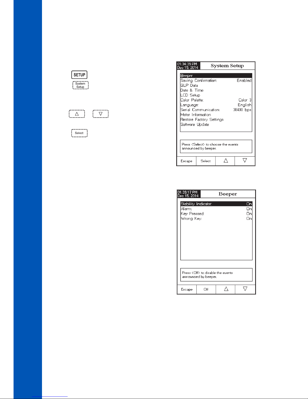
The System Setup menu allows the user to customize the user interface, view meter information,
set the external serial communication interface and to restore the manufacturer settings.
Accessing System Setup
• Press while in Measure mode.
• Press . The system setup options will be
displayed on the LCD.
To access a System Setup option:
• Use or to highlight the desired op‑
tion.
• Press to access the selected option.
The following is a detailed description of the System
Setup option screen.
Beeper
This option allows the user to turn an acoustic warning
signal on or off. This function can be used to signal 4 dif‑
ferent events: a stable signal, an alarm state, when every
key is pressed or when an incorect key is pressed. Enable
(or disable) the Beeper for these events. Disabling the
Beeper will stop audible signals.
SYSTEM SETUP
Page 15

15
Saving Confirmation
Enable this option to force verification of a change made
to a “GLP Data Option field” or a Sample ID name. If
Saving Confirmation is enabled, the user will have to
accept the change with a key stroke.
If Saving Confirmation is disabled, the changes made
to these fields change automatically without verification.
GLP Data
Use this option to customize log GLP information with specific identification data. When enabled, these
ID tags will be included in the GLP section of all data logs. Each data field can use up to 10 characters.
The five available fields are:
Operator ID : used to add the name of the operator.
Instrument ID : used to name an instrument with a discrete name, location or number.
Company Name : used to include the Company ID to the GLP data field.
Additional Info : two data fields are available for general notes or notations.
SYSTEM SETUP
Page 16

16
To add the GLP Data:
• Press while in Measure mode.
• Press .
• Use or to select the GLP Data option.
• Press and use or to highlight
the desired option.
• Press to edit the desired information. The Text
Editor menu will be displayed on the LCD.
• Enter the desired information by accepting the
highlighted character which is added to the text bar,
using . The and keys help the
user select the desired character. It is also possible to
delete the last character by positioning the cursor on
the Backspace character ( ) and pressing .
• Press to return to the GLP Data options. If the Saving Confirmation is enabled, press
to accept the modified option, to escape without saving or to return to
the editing mode. Otherwise, the modified options are saved automatically.
Date & Time
Set the current date & time and the format in which they appear. These parameters will be displayed
on the Measure screens and also when storing measured data.
Set Date and Time
This option allows the user to set the current date (year/month/day) and time (hour/minute/second).
Notes: Only years starting with 2000 are accepted.
The time is set using the selected time format. For 12 Hour time format only, the AM/PM
can also be selected with or .
Set Time Format
Choose between 12 Hour (AM/PM) time format or 24 Hour time format.
Set Date Format
Choose the desired date format from 7 available options: DD/MM/YYYY; MM/DD/YYYY; YYYY/MM/DD;
YYYY‑MM‑DD; Mon DD,YYYY; DD‑Mon‑YYYY or YYYY‑Mon‑DD.
To set the Date & Time:
• Press while in Measure mode.
• Press .
SYSTEM SETUP
Page 17

17
• Use or to select the Date & Time option.
• Press and use or to highlight the
Set Date and Time.
• Press to confirm your selection.
Use / to select next/previous entry to be
edit.
Press and use or to set the desired
value, then press to save the modified value (for
Set Date and Time option).
• For the other two options press to confirm your
selection and select one of the displayed options.
• Press to return to previous menu. If the Saving Confirmation is enabled, press to
accept the modified option, to escape without saving or to return to the editing
mode. Otherwise, the modified option is saved automatically.
Note: If the time is changed with more than one hour before last calibration, a pop-up
warning will appear on the LCD, notifying the user that a date/time conflict has occured
and some time-dependent modes could work improperly (e.g. Measure, GLP, Log).
LCD Setup
This option allows the user to set the Contrast, the Backlight of the LCD and the Backlight Saver. The
Contrast parameter can be adjusted within 7 steps, while the Backlight parameter within 8 steps.
The Backlight Saver can be set from 1 to 60 minutes or it can be OFF (disabled). All the changes are
visible on the LCD for each parameter.
Note: If the instrument backlight turnes off after the time period set, press any key to turn it
back on.
To set the LCD Setup:
• Press while in Measure mode.
• Press .
• Use or to select the LCD Setup option.
• Press and use key to highlight the desired
parameter.
• Use or to adjust the contrast / backlight
or to set the desired backlight saver time.
• Press to confirm the modified options and return
to the System Setup menu.
SYSTEM SETUP
Page 18

18
Language
This option allows the user to choose the desired language in which all information will be displayed.
To select the Language:
• Press while in Measure mode.
• Press .
• Use or to select the Language option.
• Press and use or to highlight
the desired language.
• Press to confirm your selection and return to
the System Setup menu or press to return to
the System Setup menu without changing.
Color Palette
This option allows the user to choose a desired color palette.
To select the Color Palette:
• Press while in Measure mode.
• Press .
• Use or to select the Color Palette
option.
• Press and use or to highlight the desired color.
• Press to confirm your selection and return to the System Setup menu or press to
return to the System Setup menu without changing.
Color 1 White background blue text
Color 2 Blue background white text
Color 3 White background black text
Color 4 Black background white text
SYSTEM SETUP
Page 19

19
Meter Information
This option provides general information about the instrument serial number (each instrument has
an unique identification serial number), the software version and the factory calibration date and
time (for mV and temperature).
Note: All instruments are factory calibrated for conductivity and temperature. One year after
factory calibration, the warning message “Factory Calibration Expired” will be displayed when
powering up instrument. The instrument will still function, however, it should be taken to the
nearest Hanna Customer Service for factory calibration.
To view the Meter Information:
• Press while in Measure mode.
• Press .
• Use or to select the Meter Information
option.
• Press to acces the Meter Information menu.
• Press to return to the System Setup menu.
Serial Communication
This option allows the user to set the desired speed for the
serial communication (baud rate) in bps. The meter and the
PC program must have the same baud rate.
To set the Serial Communication:
• Press while in Measure mode.
• Press .
• Use or to select the Serial Commu-
nication option.
• Press and use or to highlight
the desired baud rate.
• Press to confirm your selection and return to
the System Setup menu or press to return to the System Setup menu without changing.
SYSTEM SETUP
Page 20

20
Software update
This function allows the user to update instrument
software. In order to start the PC upgrade application, you
need to select the proper baud rate, the software update
package and start the update.
Restore Factory Settings
This option allows the user to erase all user settings and reset the instrument to the default factory
settings.
To restore the Factory Settings:
• Press while in Measure mode.
• Press .
• Use or to select the Restore Factory
Settings option.
• Press to confirm your selection. A pop‑up menu
will be displayed, asking for confirmation.
• Press to confirm your selection and return to
the System Setup or press to return to the
System Setup menu without restoring defaults.
• Press to return to Measure mode.
SYSTEM SETUP
Page 21

21
The Conductivity Setup menu allows the user to set the parameters related to the conductivity
measurement and calibration.
Accessing Conductivity Setup
• Press while in Measure mode and then
to select the Conductivity measurement
mode.
• Press and then to access
Conductivity Setup menu.
To access a conductivity setup options:
• Use or to highlight the desired op‑
tion.
• Press to access the selected option or
to exit setup.
The following is a detailed description of the Conductivity
Setup option screens.
Profile
This option opens the Profile manager. Enabling Profile allows the user to Save, Load or Delete
an application Profile. The Profile option allows the user to store up to ten separate profile
applications. Each Profile can be named and recalled at a moment’s notice. A profile is a sensor
setup complete with measurement units, logging and display preferences, calibration standards
(Standards including custom), setup of the Display screen for measurement (i.e. graphing, GLP)
and any other sensor configuration. Once saved, the exact same profile can be used at another
time. This is a handy feature if the meter is used occasionally for additional applications because
it saves time in the setup of the meter and ensures the same procedure will be used.
To save the measurement configuration for Conductivity mode:
• Press , then and use or to highlight Profile option.
• Press / to enable / disable this feature.
The available options are:
Profile Feature: enable or disable the profile feature.
Save Profile: save the current profile.
Save Profile As...: save current profile using a specific name.
Load Profile: load from available profiles.
Delete Profile: delete a profile.
CONDUCTIVITY SETUP
Page 22

22
Save Profile
To save a profile:
• Press while in Conductivity mode.
• Press .
• Use or to highlight Profile option.
• Press and then use or to
highlight Save Profile.
• Press . The existing configuration will be saved
in current profile.
Save Profile As...
To create a new profile:
• Press while in Conductivity mode.
• Press .
• Use or to highlight Profile option.
• Press and then use or to highlight Save Profile As....
• Press . The Text Editor box will be displayed on the LCD.
• Enter the desired profile name by using and to highlight the desired character
and then press to add it to the text bar. It is also possible to delete the last character by
positioning the cursor on the Backspace character ( ) and pressing .
• Press to return to the previous menu. If the Saving Confirmation is enabled, press
to accept the modified option, to escape without saving or to return to the editing
mode. Otherwise, the modified option is saved automatically.
Note: The saved profile will automatically become
the current profile.
Load Profile
To load one profile:
• Press while in Conductivity mode.
• Press .
• Use or to highlight the Profile option.
• Press and then use or to
highlight the Load Profile option.
CONDUCTIVITY SETUP
Page 23

23
Temperature
From the Temperature menu the user can choose the Temperature Source and Units, as well as the
Temperature Compensation mode, Reference Temperature, Compensation Coefficient and Compensation
Coefficient.
To access a Temperature option:
• Press while in Conductivity mode.
Delete Profile
To delete one of the existing profiles:
• Use or to highlight the Profile option.
• Press and then use or to highlight
the Delete Profile option.
• Press . A list with all customised profiles will appear
on the screen.
• Use or to select the desired profile and
press .
• Press to return to the previous menu.
Reading Mode
This option allows the user to select between Direct, Direct/AutoHold or Direct/USP conductivity
reading modes.
Note: All three selections permit conductivity to be changed to resistivity, TDS and salinity via
the key.
To set the reading mode:
• Press while in Conductivity mode.
• Press .
• Use or to highlight the Reading Mode
option.
• Press and then use or to highlight
the desired option.
• Press to confirm your selection or press to
cancel operation.
• Press . A list with all customized profiles will be displayed on the screen.
• Use or to select the desired profile and press to confirm or to
exit without selecting.
CONDUCTIVITY SETUP
Page 24

24
• Use or to highlight the Temperature option from the Conductivity Setup menu.
• Press to access the Temperature option.
Temperature Source
To set the temperature source:
Note: The HI76312 sensor has an integrated temperature sensor and will provide the best
conductivity measurement. Use Automatic to use sensor or Manual. When manual, the value
will have to be adjusted using when in measurement mode.
• Use or to highlight the Temperature
Source option.
• Press to select Manual or to select
Automatic temperature source.
Temperature Compensation
The user can choose from the following options:
Linear - the meter will automatically compensate the
conductivity using the following formula:
where:
C
ref
‑ conductivity at reference temperature
CI ‑ conductivity at temperature of measurement
α ‑ compensation coefficient
TI ‑ temperature in °C
T
ref
‑ reference temperature
Non-Linear - recommended for measuring the conductivity of the natural water in accordance with the
ISO‑788‑1985. It provides compensation in the range of 60 to 1000 µS/cm over a temperature
range of 0 ‑ 35 °C.
Disabled - the meter will display the Absolute conductivity with no temperature compensation.
C
ref
=
C
I
1 + α (TI - T
ref
)
100
To set the temperature compensation mode:
• Use or to highlight the Temperature Compensation option.
• Press and then use or to select Linear, Non-Linear or Disabled
option.
CONDUCTIVITY SETUP
• Press .
Page 25

25
Temperature Unit
The user can choose from the Celsius, Fahrenheit or Kelvin
temperature units.
To set the temperature unit:
• Press and then use or to high‑
light the Temperature Unit option.
• Press and then use or to select
Celsius, Fahrenheit or Kelvin unit.
• Press to confirm your selection or press to
cancel operation.
Reference Temperature
(Linear or Non‑Linear temperature compensation only)
Note: ISO -7888-1985 requires a reference temperature
of 25 °C.
To set the reference temperature:
• Use or to highlight the Temperature
option.
• Press and then use or to high‑
light the Reference Temperature option.
• Press and then use or to
increase / decrease the value.
• Press to save or press to cancel operation.
• Press to confirm your selection or press to
cancel operation.
Note: Whatever form of compensation is used,
the reading will not be as accurate as taking a
reading of the sample’s conductivity at the reference
temperature.
CONDUCTIVITY SETUP
Page 26

26
Compensation Coefficient (Linear temperature compensation only)
The temperature coefficient is a factor used to express the rate a solution’s conductivity increases
with an increase in temperature and is expressed as a % increase in conductivity, for a temperature
change of 1 °C. The coefficient differs for different binary solutions. For typical aqueous dilute salt
mixtures, 1.90 %/°C is used. Ultrapure water is 5.50 %/°C.
To set the compensation coefficient:
• Use or to highlight the Temperature
option.
• Press and then use or to
highlight the Compensation Coefficient option.
• Press and set the desired compensation coef‑
ficient using or to increase/decrease
the value.
• Press to save the current value or press
to cancel operation.
Calibration
The conductivity probe can be calibrated using the con‑
ductivity standards or by entering the cell constant of the
probe by the user.
Using standard solutions:
The probe and the meter can be calibrated with a single standard or with multiple standards (up to four
points), choosing from 6 Hanna standards (84 µS/cm, 1413 µS/cm, 5.0 mS/cm,12.88 mS/cm,
80.0 mS/cm, 111.8 mS/cm) or using the custom standards. Multiple point calibrations are used to
increase accuracy when measurements are made over an extended range. Choose standards that are
in the sample measurement range of interest. Use only one standard at each measurement range.
Measurement Range Calibration Standards
0 ‑ 200 µS/cm 84.00 µS/cm
200 ‑ 2000 µS/cm 1413 µS/cm
2 ‑ 20 mS/cm 5.000 or 12.88 mS/cm
20 ‑ 1000 mS/cm 80.0 or 111.8 mS/cm
CONDUCTIVITY SETUP
Page 27

27
Calibration Points
The user can choose between Single Point and Multi Points calibration.
To set the calibration points:
• Press while in Conductivity mode.
• Press .
• Use or to highlight the Calibration
option.
• Press and then use or to
highlight the Calibration Points option.
• Press to choose Multiple Points calibration.
• Press to choose Single Point calibration.
The following options are available for calibration:
Standard Recognition
The user can choose between Automatic recognition (from 6 Hanna standards available) or User
Standard (when custom standards are used for calibration).
• Press while in Conductivity mode.
• Press .
• Use or to highlight the Calibration
option.
• Press and then use or to
highlight the Standard Recognition option.
• Press to choose Automatic recognition mode.
• Press to choose User Standard mode.
CONDUCTIVITY SETUP
Page 28

28
Calibration Reminder
This option allows the user to set the calibration reminder as Daily, Periodic or Disabled.
To set the calibration reminder:
• Press while in Conductivity mode.
• Press .
• Use or to highlight the Calibration
option.
• Press and then use or to
highlight the Calibration reminder option.
• Press to confirm your selection and then use
or to choose the desired option.
• Press to confirm your selection or press
to cancel operation.
Set Reminder Period
Daily reminder ‑ the user can set the time of day when the reminder is to appear.
Periodic reminder ‑ the user can set the time from the last calibration (days, hours and minutes)
after which the reminder appears.
To set the reminder period:
• Press while in Conductivity mode.
• Press .
• Use or to highlight the Calibration
option.
• Use or to highlight the Set Reminder
Period option.
• Press and use / to select
next / previous entry to be edited.
• Press and use or to set the
desired value, then press to save the modified
value or press to cancel operation.
• Press to return to the previous menu.
CONDUCTIVITY SETUP
Page 29

29
Clear Calibration
Accessing this option, the existent conductivity calibration can be cleared. If the calibration is cleared,
another calibration has to be performed.
To clear calibration:
• Press while in Conductivity mode.
• Press .
• Use or to highlight the Calibration option.
• Use or to highlight the Clear Calibration option.
• Press to clear calibration. A pop‑up menu will be displayed asking for confirmation (if
calibration is available).
• Press to confirm or press to escape without saving and return to the Calibration
options.
Cell Constant
Cell constant manual editing:
The conductivity probe can also be calibrated by entering the cell constant value.
To edit the cell constant value:
• Press while in Conductivity mode.
• Press .
• Use or to highlight the Cell Constant
option.
• Press to reset the cell constant value to default
(1.0000/cm).
• Use / to increase / decrease the
value.
• Press to confirm the new value or press
to exit without modifying.
Probe Type
This option allows the user to obtain some information about the connected conductivity probe: name,
default cell constant, range and rings number. The HI76312 probe is recognized by the meter.
CONDUCTIVITY SETUP
Page 30

30
Units
The user can select the desired measurement unit. The available options are: µS/cm, mS/cm or
AutoRanging.
• Press while in Conductivity mode.
• Press .
• Use or to highlight the Units option.
• Press and then use or to
select µS/cm, mS/cm or AutoRanging.
• Press to confirm your selection or press
to cancel operation.
Sample ID
This option allows the user to assign an identification number/name to sample logs. Two Sample ID
parameters are available: ID Increment mode and Edit Sample ID.
ID Increment
Choose None to identify a sample with a text tag.
Choose Automatic to identify a sample with a numeric tag. This number will be incremented by
one for each new lot log but it can also be altereted manually here. This number does not increment
for each manual log sample. This will be automatically
incremented when a New Lot will be selected.
To select the ID increment mode:
• Press while in Conductivity mode.
• Press .
• Use or to highlight the Sample ID
option.
• Use or to highlight the ID Increment
option.
• Press or as desired.
• Press to return to previous menu.
CONDUCTIVITY SETUP
Page 31

31
Edit Sample ID
This option allows the user to edit the sample ID. If ID increment is None, a Text Editor screen is
displayed. If ID increment is Automatic, a Numeric Editable screen is displayed.
To access the Sample ID:
• Press while in Conductivity mode.
• Press .
• Use or to highlight the Sample ID
option.
• Press and use or to highlight
the Edit Sample ID option.
• Press to confirm your selection.
• For text editing use and to highlight
the desired character and then press to add
it to the text bar. It is also possible to delete the last
character by positioning the cursor on the Backspace
character ( ) and pressing .
• Press to return to Sample ID option.
If the Saving Confirmation is enabled, press to
accept the modified option, to escape without
saving, or to return to the editing mode. Other‑
wise, the modified options are saved automatically.
• For numeric editing use or keys.
• Press to save the current value or press
to cancel operation.
Log
Note: See Logging section for available types of logging.
This option allows the user to edit the log settings: Logging Type, Logging Data Configuration, Sampling
Period and New Lot.
Logging Type
Three logging types are available: Automatic, Manual and Auto Hold.
CONDUCTIVITY SETUP
Page 32

32
Automatic ‑ the measurement data is logged automatically at constant time intervals.
Manual ‑ a snapshot of the displayed measurement data is logged with time stamp when the user
manually depresses Log.
Auto Hold ‑ this is configured along with the Direct/AutoHold reading mode to take a snapshot of
stable measurement data. Press to initiate a logging session. Press to
initiate an Auto Hold event. The log occurs automatically once measurement stability is
reached. This type log removes subjective data, as it only captures stable measurements.
To set the Logging Type:
• Press while in Conductivity mode.
• Press .
• Use or to highlight the Log option.
• Press and use or to highlight
the Logging Type option.
• Press and use or to highlight
the desired option.
• Press to confirm your selection or press
to cancel operation.
Logging Data Configuration
This option allows the user to select which parameters will accompany a log file: Date/Time,
Calibration Data, Sample ID, Instrument ID, Operator ID, Company Name, Additional Info 1 and
Additional Info 2.
To set the Logging Data Configuration:
• Press while in Conductivity mode.
• Press .
• Use or to highlight the Log option.
• Press and use or to highlight
the Logging Data Configuration option.
• Press and use or to highlight
the desired parameter to be logged in file.
• Press to enable the parameter or to
disable it.
• Press to return to previous menu.
CONDUCTIVITY SETUP
Page 33

33
Sampling Period
This option allows the user to select the desired sampling period for automatic logs.
To set the Sampling Period:
• Press while in Conductivity mode.
• Press .
• Use or to highlight the Log option.
• Press and use or to highlight
the Sampling Period option.
• Press and use or to select the
desired option.
• Press to confirm your selection or press
to cancel operation.
New Lot
This option is used to create a new lot when manual logging is used.
Note: If New Lot option is accessed and the Logging Type is Automatic, a warning message
appears on the LCD informing the user that a new lot can be created only if the Logging Type
is set as Manual.
To generate a New Lot:
• Press while in Conductivity mode.
• Press .
• Use or to select the Log option.
• Press and use or to highlight the New Lot option.
• Press to generate a new manual lot. A pop‑up menu will be displayed asking for
confirmation.
• Press to confirm or press to escape without saving and return to the Log options.
Alarm
This option allows the user to select the alarm settings: Alarm State and Alarm Limits. If the Alarm
option is enabled, a continuous double beep will be heard, along with the “Alarm” indicator blinking
on the LCD, each time the set limits in Measure mode are exceeded.
Note: Alarm Beeper must be set On for audible beep to be heard. See: System Setup →
Beeper → Alarm.
CONDUCTIVITY SETUP
Page 34

34
Alarm State
Three settings are available for the Alarm State option:
Disabled ‑ the alarm will be disabled.
Inside Limits ‑ the alarm state will trigger when the
measured value is inside the set limits.
Outside Limits ‑ the alarm state will trigger when the
measured value is outside the set limits.
To set the Alarm State:
• Press while in Conductivity mode.
• Press .
• Use or to select the Alarm option.
• Press and use or highlight
the Alarm State option.
• Press and use or to highlight the desired option.
• Press to confirm your selection or press to cancel operation.
Alarm Limits
This option allows the user to set the alarm limits for the measured value.
Note: The Alarm High value can not be lower than the Alarm Low value.
• Press while in Conductivity mode.
• Press .
• Use or to select the Alarm option.
• Press and use or highlight
the Alarm Limits option.
• Press and then use or to
set the desired value, then press to save the
modified value or press to cancel operation.
• Press to return to the Alarm options.
CONDUCTIVITY SETUP
Page 35

35
The Resistivity Setup menu allows the user to set the parameters related with the resistivity
measurements.
Accessing Resistivity Setup
• Press and then to select resistivity
measurement mode.
• Press and then to access Resistivity
Setup menu.
To access a Resistivity Setup option:
• Use or to select the desired option.
• Press to confirm your selection.
The following is a description of the Resistivity Setup
option screens.
Profile ‑ see Conductivity Setup section.
Reading Mode
This option allows the user to select between Direct and Direct/AutoHold resistivity reading modes.
To set the Reading Mode:
• Use or to highlight the Reading Mode
option.
• Press / to select Direct /
Direct/AutoHold option as desired.
• Press to cancel operation.
RESISTIVITY SETUP
Page 36

36
Temperature - see Conductivity Setup section.
Units
The user can choose between Ω.cm, KΩ.cm, MΩ.cm or AutoRanging units.
To select the units:
• Press while in Resistivity mode.
• Press .
• Use or to highlight the Units option.
• Press to confirm and then use or
to highlight the desired unit.
• Press to confirm or press to cancel
operation.
Sample ID - see Conductivity Setup section.
Log - see Conductivity Setup section.
Alarm - see Conductivity Setup section.
RESISTIVITY SETUP
Page 37

37
The TDS Setup menu allows the user to set the parameters related to the TDS measurement.
Accessing TDS Setup
• Press and then to select TDS (Total Dissolved Solids) measurement mode.
• Press and then to access TDS Setup menu.
To access a TDS Setup option:
• Use or to highlight the desired op‑
tion.
• Press to access the selected option.
The following is a description of the TDS Setup option
screens.
Profile - see Conductivity Setup section.
Reading Mode ‑ see Resistivity Setup section.
Temperature - see Conductivity Setup section.
Units
This option allows the user to set the TDS measuring unit ppm (mg/L), ppt (g/L) or AutoRanging units.
To select the suitable unit:
• Press while in TDS mode.
• Press .
• Use or to highlight the Units option.
• Press to confirm and then use or
to highlight the desired unit.
• Press to confirm your selection or press
to cancel operation.
TDS SETUP
Page 38

38
TDS factor
TDS factor is a conversion factor used to convert conductivity to TDS by the equation:
TDS = Factor x EC25. The TDS conversion factor can be set from 0.40 to 1.00. A typical TDS conver‑
sion factor for a strong ionic solutions is 0.50, while for a weak ionic solutions (e.g. fertilizers) is 0.70.
Example:
TDS factor
0.5 µS/cm x 0.41 = 0.205 ppm NaCl
The default value is 0.50.
This option allows the user to set the TDS factor:
• Press while in TDS mode.
• Press .
• Use or to highlight the TDS Factor
option.
• Press to confirm your selection and use
or to increase / decrease the value.
• Press to confirm your selection or press
to cancel operation.
Sample ID - see Conductivity Setup section.
Log - see Conductivity Setup section.
Alarm - see Conductivity Setup section.
TDS SETUP
Page 39

39
Salinity measurements are related to the salt in ocean water.
The Salinity Setup menu allows the user to set the parameters related to Salinity measurement
and calibration.
Accessing Salinity Setup
• Press and then to select Salinity measurement mode.
• Press and then to access Salinity Setup menu.
To access a Salinity Setup option:
• Use or to highlight the desired
option.
• Press to access the selected option.
The following is a description of the Salinity Setup
option screens.
Profile - see Conductivity Setup section.
Reading Mode - see Resistivity Setup section.
Temperature - see Conductivity Setup section.
To set one of the Temperature options:
• Press while in Salinity mode.
• Press .
• Use or to highlight the Temperature option.
• Press and then use or to highlight the desired Temperature option you
wish to modify.
• Press and then use or to highlight the desired option (for Temperature
Source & Unit options) or use or to adjust the temperature value between the
displayed limits (for Manual Temperature option).
• Press to confirm your selection (for Temperature Source & Unit options) or press
to save the current value (for Manual Temperature option). Otherwise, press to cancel
operation.
SALINITY SETUP
Page 40

40
Clear Calibration
This function only works for the Percent Scale.
To clear calibration:
• Press while in Salinity mode.
• Press .
• Use or to highlight the Clear Calibration option.
• Press to clear calibration. A pop‑up menu will be displayed asking for confirmation
(if calibration is available).
• Press to confirm or press to cancel operation.
Salinity Scale
Note: See Salinity Measurement for a description of these scales.
The meter has three ocean salinity scales: Natural Sea Water 1966, Practical Scale 1978, Percent
Scale [%].
To select the desired salinity measurement scale:
• Press while in Salinity measure mode.
• Press .
• Use or to highlight the Salinity Scale
option.
• Press and use or to highlight
the desired option.
• Press to confirm your selection or press
to cancel operation.
Sample ID - see Conductivity Setup section.
Log - see Conductivity Setup section.
Alarm - see Conductivity Setup section.
SALINITY SETUP
Page 41

41
For optimum measurements:
• Insert probe in the center of the beaker away from container bottom or walls.
• Fix the probe so it does not move during measurements and add sufficient solution to cover top
vent holes on probe.
• Gently stir solution and wait for probe to reach thermal equilibrium and verify no bubbles are
entrapped within probe electrodes.
It is recommended to calibrate the instrument frequently, especially if high accuracy is required.
The conductivity range should be recalibrated:
• Whenever the conductivity probe is replaced.
• At least once a week.
• Before USP measurements.
• After testing aggressive chemicals.
• When calibration reminder is activated (“Conductivity Cal Expired”).
• If the readings are far from the calibration point.
Note: TDS, Resistivity and Natural Sea Water and Practical Sea Water Salinity readings are
automatically derived from the conductivity readings so conductivity calibration is required.
OFFSET CALIBRATION
The meter allows the user to calibrate the probe for an offset.
• Press and then press .
• Select the automatic standard recognition (see Conductivity Setup → Calibration).
• Leave the dry probe in the air (infinite resistance).
• Enter in calibration mode by pressing .
• Clear any previous calibrations by pressing .
• Wait to stabilize. The 0.000 µS/cm calibration point will appear on the screen.
• Press to finish the probe offset calibration.
• Press to exit calibration mode or continue calibration in the other standard solutions.
Note: The offset calibration can be performed only if it is performed first (no other calibration
points present). Clear the old calibration if it is present.
CELL CONSTANT CALIBRATION (in solution)
Single-Point Calibration
• Select the single point calibration (see Conductivity Setup → Calibration).
CONDUCTIVITY CALIBRATION
Page 42

42
• Pour a small quantity of the standard solution into a clean beaker. If possible, use plastic
beakers to minimize any EMC interferences.
• For accurate calibration and to minimize cross‑contamination, use two beakers for each standard
solution. One for rinsing the probe and one for calibration.
• Insert the probe in the rinse beaker.
• Swirl probe in this solution. Raise and lower 3 times to fill cell with solution.
• Insert the probe in the second beaker.
• Swirl and tap probe to remove air bubbles. Raise and lower 3 times to ensure representative
sample.
• Enter calibration mode by pressing . Wait to stabilize.
• If automatic standard recognition was selected in Setup, a calibration point will be auto‑
matically displayed from the Hanna standard list (84 µS/cm, 1413 µS/cm, 5.0 mS/cm,
12.88 mS/cm, 80.0 mS/cm, 111.8 mS/cm). The user can also select another standard value
by using and .
• If User Standard was selected in Setup, a pop‑up will prompt for the custom standard value.
• Press to finish the calibration or to abort calibration.
• The probe should be rinsed in deionized water.
• Shake off excess water.
Note: The calculated cell constant will be used for the whole range.
Multi-Point Calibration
• Up to 4 calibration points can be performed in order to
increase the measurement accuracy over a larger measure‑
ment range.
• Select the multi point calibration (see Conductivity Setup
→ Calibration).
• Repeat the steps from the single point calibration for
each measurement range. The meter will calculate a cell
constant corresponding to each calibration point.
• Press to exit calibration mode.
Note: For each range the corresponding cell constant
will be displayed.
CELL CONSTANT CALIBRATION (edited by the user)
• A known value of the probe cell constant can be set by the user for the whole range (see
Conductivity Setup → Cell Constant section). Using a known cell constant is another way to
calibrate the meter/probe system.
CONDUCTIVITY CALIBRATION
Page 43

43
CALIBRATION MESSAGES
• Wrong standard solution. Check the standard solution. This message appears when the
difference between the reading and the value of the selected standard is significant. If this
message is displayed, check if you have selected the appropriate calibration standard.
• Wrong standard temperature. This message appears if the standard temperature is out of
the allowable standard temperature range (0 ‑ 60 °C).
• The current range was already calibrated. Change the standard solution. The calibration
for this conductivity range was already done. Please change the standard.
• Press <Clear Offset> to clear old calibration. Clear the offset of the electrode calibration.
• Press <Clear Cal> to clear old calibration. Clear all old calibrated standards.
Make sure the instrument has been calibrated before taking conductivity measurements.
DIRECT MEASUREMENT
To measure the conductivity of a sample using the Direct reading mode:
• Press and then to select conductivity measure mode.
• Select the Direct reading mode (see Conductivity Setup).
• The conductivity probe should be rinsed with deionized water.
• Shake off excess water.
• If possible rinse probe with a sample of solution to be tested. Swirl and raise and lower probe
in this rinse solution.
• Insert probe in center of a beaker with the sample,
away from the wall or bottom of beaker. The upper
vent holes must be covered with solution.
• Gently stir solution and wait for probe to reach thermal
equilibrium with the sample.
• Tap probe repeatedly to dislodge any air bubbles that
may be trapped inside the sleeve. Allow time for the
reading to stabilize.
• The measured conductivity value will be displayed on
the screen.
Note: When a cell constant value is used, the solution calibration will be cleared. A solution
calibration can still be made after entering a cell constant value.
CONDUCTIVITY MEASUREMENT
Page 44

44
The United States Pharmacopoeia Regulations establishes limits and calibration requirements for
WFI (Water For Injection). The HI5321 meter supports conductivity measurements that are needed
for off line measurements in a Stage 2 of the regulation. Stage 1 verification may be carried out in
a container but the regulation requires an in‑line measurement. The meter provides prompts and
instructions to make the measurements easily. Calibrate an EC probe prior to starting USP analysis.
To access the USP menu:
• Select from the basic display to select
• Press then .
• Select the Direct/USP reading mode (see Conductivity
Setup).
• Return to measure mode by pressing .
• Verify conductivity probe has been calibrated in
conductivity standards in the lowest measurement
range.
• Press and then select the desired USP stage.
In this measure mode the user can check for water
quality using the United States Pharmacopeia standard
(USP <645>) guidelines for water for injection.
This USP standard consists of three stages (one in‑line and two off‑line tests) as followings:
DIRECT/AUTOHOLD MEASUREMENT
To measure conductivity of a sample using the
Direct/AutoHold reading mode:
• Follow sample and probe directions found under
Direct Measurement.
• Select the Direct/AutoHold reading mode(see Con‑
ductivity Setup).
• If pressing , the “AutoHold” indicator will start
blinking on the display until the stability criterion is
reached. The conductivity value will be frozen on the
display, along with “AutoHold” indicator.
• To return to normal measure mode press .
CONDUCTIVITY MEASUREMENTUSP EVALUATION
Page 45

45
Stage 1 ‑ this is an in‑line test.
The procedure follows:
• Measure the temperature of the water and the absolute
conductivity readings. The measurement must be an
in‑line measurement. Results may be verified using a
laboratory method.
• The temperature should be rounded down to the
nearest 5 °C. Look up the corresponding conductivity
value in the table on the next page.
• If the measured conductivity is lower than the
conductivity in the table, then the water meets the
USP requirements.
• Otherwise, proceed to Stage 2 testing.
Stage 1 steps:
Press from the keypad.
• An instruction prompt will pop up.
• Using measurement technique outlined in direct measurement, place probe into sample.
• Press .
• The user may edit the USP factor by pressing (to provide a margin of error) or compare
measurement results directly to the standard (100%). “Please wait ...” will appear on display
and the measurement is compared to the standard values.
• At the conclusion of the test period the results will be displayed.
• The user may view the results as a report. Press .
• A copy of the sample results may also be saved. Press . This may be printed using HI92000
software.
USP EVALUATION
Temperature
(°C)
Conductivity
(µS/cm)
Temperature
(°C)
Conductivity
(µS/cm)
Temperature
(°C)
Conductivity
(µS/cm)
0 0.6 35 1.5 70 2.5
5 0.8 40 1.7 75 2.7
10 0.9 45 1.8 80 2.7
15 1.0 50 1.9 85 2.7
20 1.1 55 2.1 90 2.7
25 1.3 60 2.2 95 2.9
30 1.4 65 2.4 100 3.1
Page 46

46
Stage 2 steps:
Note: A temperature bath at 25.0 ±1.0 °C is required
for this measurement.
• Press from the keypad.
• An instruction prompt will pop up with instructions for
sample preparation.
• Using measurement technique outlined in direct measure‑
ment, place probe into sample.
• Press .
• The meter will begin to evaluate stability of the conductivity measurement. At the conclusion of
the test period the results will be displayed. If the sample has passed the evaluation the testing
is finished and the water may be used.
• Press to store a copy of the sample results. This
may be printed using HI92000 software.
Note: A separate pH meter and sensor is required.
Stage 3 ‑ this is an off‑line test that studies the pH and CO2.
If the water sample has failed Stage 1 and Stage 2 tests,
Stage 3 testing must be conducted.
To perform this test pH measurement is required. Have a
calibrated pH sensor.
Stage 2 ‑ this is an off‑line test.
To perform this test:
• Store the water sample in an enclosed clean container
that has been rinsed previously with water of the same
quality.
• Adjust the sample’s temperature to 25 °C and agitate the
sample to ensure that it has equilibrated with ambient
CO2.
• If the measured conductivity is less than 2.1 µS/cm, then
the sample has met the USP requirements.
• Otherwise, proceed to Stage 3 testing.
USP EVALUATION
Page 47

47
Note: A temperature bath at 25.0 ±1.0 °C is required
for this measurement.
• Take the water sample from the stage 2 test and increase
its ionic strength for a pH measurement at 25 °C.
• Use 100 mL of Stage 2 water and add 300 µL saturated
KCl to the sample.
• Calibrate a pH sensor in pH 4.01 and pH 6.86 (or 7.01)
buffers.
• Thermally equilibrate the sample to 25.0 ±1.0 °C.
• Measure sample with the calibrated pH sensor.
• The pH of sample must be between 5.0 and 7.0 pH.
• Record the pH and round it to the nearest 0.1 pH.
• Find the measured pH and corresponding conductivity in the stage 3 table.
• Compare the conductivity value determined in stage 2 to the conductivity value found in the
stage 3 table.
• If the stage 2 conductivity is lower than the conductivity from the table below, the sample has
meet the USP requirements. Otherwise, the water didn’t meet the USP requirements.
USP EVALUATION
pH Conductivity
(µS/cm)
pH Conductivity
(µS/cm)
pH Conductivity
(µS/cm)
5.0 4.7 5.7 2.5 6.4 2.3
5.1 4.1 5.8 2.4 6.5 2.2
5.2 3.6 5.9 2.4 6.6 2.1
5.3 3.3 6.0 2.4 6.7 2.6
5.4 3.0 6.1 2.4 6.8 3.1
5.5 2.8 6.2 2.5 6.9 3.8
5.6 2.6 6.3 2.4
Page 48

48
Make sure the TDS factor has been set before taking TDS measurements (see TDS Setup section).
Also the TDS calibration is made in Conductivity mode.
DIRECT MEASUREMENT
To measure the TDS of a sample using the Direct reading
mode:
• Press and then to select TDS measure
mode.
• Select the Direct reading mode (see TDS Setup section).
• Proceed the same as for the conductivity measurement
(see Conductivity Measurement section).
DIRECT/AUTOHOLD MEASUREMENT
To measure resistivity of a sample using the Direct/
AutoHold reading mode:
• Select the Direct/AutoHold reading mode (see
Resistivity Setup section).
• Proceed the same as for the conductivity measurement
(see Conductivity Measurement section).
• Press and then to select resistivity
measure mode.
• Select the Direct reading mode (see Resistivity Setup
section).
• Proceed the same as for the conductivity measurement
(see Conductivity Measurement section).
Make sure the instrument and probe has been calibrated in conductivity mode before taking
resistivity measurements.
DIRECT MEASUREMENT
To measure the resistivity of a sample using the Direct
reading mode:
RESISTIVITY MEASUREMENT
TDS MEASUREMENT
Page 49

49
Note: Salinity calibration is made in conductivity mode when using Natural Sea Water or
Practical Sea Water measurement. Direct salinity calibration is only possible when using the
older percent scale.
Salinity calibration is a single‑point calibration procedure at 100.0%. Use the HI7037 calibration
solution (salinity solution) as a 100% seawater solution.
To enter salinity calibration:
• Set the meter for salinity range.
• Select the Percent Scale (see Salinity Setup section).
• Rinse the probe with some of the calibration solution or deionized water.
• Immerse the probe in HI7037 solution. The sleeve holes must be completely submerged. Tap
the probe repeatedly to remove any air bubbles that may be trapped inside the sleeve. Position
probe away from the wall or bottom of the container.
• Enter in calibration mode by pressing .
• Wait for measurement to stabilize.
• Press to finish salinity calibration or press to cancel calibration.
CALIBRATION MESSAGES
• Wrong standard solution. Check the standard solution. This message appears when the
difference between the reading and the value of the selected standard is significant. If this
message is displayed, check if you have selected the appropriate calibration standard.
• Wrong standard temperature. This message appears if the standard temperature is out of
the allowable standard temperature range (0 ‑ 60 °C).
• Press <Clear Cal> to clear old calibration.: Clear the old calibration.
DIRECT/AUTOHOLD MEASUREMENT
To measure TDS of a sample using the Direct/AutoHold
reading mode:
• Select the Direct/AutoHold reading mode (see TDS Setup
section).
• Proceed the same as for the conductivity measurement.
(see Conductivity Measurement section).
SALINITY CALIBRATION
Page 50

50
S = - 0.08996 + 28.2929729R15 + 12.80832R
15
2
- 10.67869R
15
3
+ 5.98624R
15
4
- 1.32311R
15
5
Note: The formula can be applied for temperatures between 10 °C and 31 °C.
PRACTICAL SALINITY SCALE (UNESCO 1978)
The PSU scale extends from 0.00‑42.00 PSU. The Practical salinity (S) of seawater relates the ratio
of electrical conductivity of a normal seawater sample at 15 °C and 1 atmosphere to a potassium
chloride solution (KCl) with a mass of 32.4356 g/kg water at the same temperature and pressure.
Under these conditions the ratio is equal to 1 and S=35. The Practical salinity scale may be
applied to values 2 through 42.00 PSU at temperature between ‑2 °C to 35 °C.
S is defined in terms of the ratio K
15
.
S = 0.0080-0.1692K
15
1/2
+25.3851K15+14.0941K
15
3/2
-7.0261K
15
2
+2.7081K
15
5/2
Where C is Conductivity;
C(35,15,0)=0.042933 S/cm
The simplified equation above is derived from
With the following coefficients and k = 0.0162 and
Seawater temperature coefficient r
T
= c0 + c1·T + c2·T2 + c3·T3 + c4·T
4
S = a0 + a1·R
T
1/2
+ a2·RT + a3·R
T
3/2
+ a4·R
T
2
+ a5·R
T
5/2
+
(T - 15)
·
[b0 + b1·R
T
1/2
+ b2·RT + b3·R
T
3/2
+ b4·R
T
2
+ b5·R
T
5/2
]
1 + k(T-15)
R =
C
(S,T,P)
= (RP·RT·rT)
C
(35,15,10)
K
15
=
C(S,15,0)
C(KCl,15,0)
C(35,15)·r
T
R15=
CT(sample)
RT=
R
RP·r
T
RP=1+
P·(A1 + A2·P + A3·P2)
1+B1·T + B2·T2 + B3·R + B
4
·R·T
;
where R15 is the conductivity ratio, and Salinity is defined by the following
equation.
NATURAL SEA WATER SCALE (UNESCO 1966)
The Natural Sea Water Scale extends from 0.00 ‑ 80.00 ppt. It determines salinity based upon a
conductivity ratio of sample to “standard seawater” at 15 °C.
Three methods for calculating seawater salinity are supported (Natural Sea Water Scale, Practical
Salinity Scale and Percent Scale).
PERCENT SCALE (1902)
This salinity scale extends from 0.0 to 400.0%. The formula followed is: S
%
= 1.805Cl + 0.03
where salinity is defined as the total amount of solid materials in grams dissolved in one kilogram
of seawater. 100% Salinity has ~10% solids and is considered normal seawater.
SALINITY MEASUREMENT
Page 51

51
The user temperature calibration menu can be accessed during meter startup by simultaneously
pressing three keys as shown in the drawing below. Press the keys after the short beep is heard at
the meter power on. Keep all three keys pressed until Temp. Calibration menu appear.
Note: The user temperature calibration is performed at three points: around 0 °C, 50 °C
and 100 °C.
To perform the user temperature calibration:
• Press to start the temperature calibration.
Adjust the temperature preset value using
or when necessary.
• Insert the EC probe into the beaker with water at
0 °C.
• Wait for measurement to stabilize and then press
to confirm the calibration point.
• Repeat the previous steps for 50 °C and 100 °C.
• Save the calibration.
• Press to return to measure mode.
Note: Press if you want to clear the
temperature user calibration.
a0=0.008 b0=0.0005 A1=2.070·10
‑5
c0=6.766097·10
‑1
a1=‑0.1692 b1=‑0.0056 A2=-6.370·10
‑10
c1=2.00564·10
‑2
a2=25.3851 b2=‑0.0066 A3=3.989·10
‑15
c2=1.104259·10
‑4
a3=14.0941 b3=‑0.0375 B1=3.426·10
‑2
c3=-6.9698·10
‑7
a4=‑7.0261 b4=0.0636 B2=4.464·10
‑4
c4=1.0031·10
‑9
a5=2.7081 b5=‑0.0144 B3=4.215·10
‑1
B4=-3.107·10
‑3
TEMPERATURE CALIBRATION
Page 52

52
Reading Mode Log log Recall
Automatic (1) Automatic Log
Direct Manual (2) Manual Log
Auto Hold (NA) Not Applicable
Automatic (3) Automatic Log
Direct/AutoHold Manual (4) Manual Log
Auto Hold (5) Manual Log
There are 5 ways the Reading Mode and Log may be configured together. The table below shows
the combinations and indicates where the completed log will be stored.
2) Direct Reading Mode and Manual Log:
Real time continuous measurements are on display and snapshots
of measurement data are stored in the Manual log when
the user presses . Subsequent snapshots will be
added to the same Manual Lot every time the is
depressed unless New Lot is selected under Log options.
Note: When the is pressed the lot ID along
with the current record number will appear for short
time on the selected channel window on the top/left
corner (e.g. L001_EC 4 - this means lot ID L001_EC
and recod number 4).
1) Direct Reading Mode and Automatic Log:
Real time continuous measurements are on display and
continuous logs to meter memory. These are sometimes referred
as interval logs. Press .
LOGGING
Page 53

53
3) Direct/AutoHold Reading Mode and Automatic Log
Press and then keys must be pressed on
front display to initiate this function. Real time continuous
measurements are on display with “AutoHold” flashing and
real time continuous logging into meter memory, until the
meter reaches the stability criteria to go into Auto Hold
mode. The stored sample logs will be marked with an “H”
to indicate the Auto Hold mode. The virtual key
returns operation to real time continuous measurements
and stops the logging session.
4) Direct/AutoHold Reading Mode and Manual Log
Press in order to add one new record in the log
report. The manual log is working even if it is in Auto Hold or Continuous reading mode. Press
to initiate the Auto Hold event. “AutoHold” will flash until the stability criteria is reached
and then the screen freezes in Auto Hold mode, the data is marked with an “H”.
5) Direct/AutoHold Reading Mode and Auto Hold Log
Press and then keys to initiate and automate the capture of stable data which is
stored in the Recall Manual Log file. During the process, “AutoHold” will flash until the stability
criteria is reached and then the screen freezes in Auto Hold mode, the data is logged and marked
with an “H”. The virtual key returns operation to Real time continuous measurement.
Press again to log a second stable data point. The lot ID along with the record index will
appear for short time on the top/left corner on the selected channel window, every time a record
will be added to the lot.
LOG RECALL
This feature allows the user to view all stored data. If no
data were logged, the “No records were found.” message
will be displayed on the LCD in the Log Recall screen.
Otherwise, the instrument will display all the memorized
lots in accordance with the selected option: Automatic Log,
Manual Log or USP Reports.
To view the memorized data:
• Press while in Measure mode.
• Press and then select the log report type.
LOGGING
Page 54

54
• Press , or to select the desired
Log Report type. All logged lots for the selected Log
Report type will be displayed on the LCD.
• To filter the displayed lots, press and then the
desired parameter. Only the selected measurement
parameter lots will be displayed on the LCD.
• Select the desired lot with or and
press to display the logged data from the
highlighted lot. The “Please wait...” message will
be displayed on the LCD for one second. The se‑
lected Logging Data Configuration options will be
displayed on the LCD, together with GLP information
(last calibration date and calibrated standards) if a
calibration has been performed on the selected mode
and the logged values (measured value, temperature
value, temperature compensation mode and the
logging time).
Note: For automatic logging only, it is possible to view
the plotted graph.
Press to display the graph.
By pressing it is possible to move the graph
along the X or Y axis with the arrow keys.
If pressing while the graph is displayed, the
zoom menu for the X and Y axes will be accessed.
Press , or / / /
to switch between the active zooming axes
and then zoom in or out on the selected axis by
pressing the appropriate virtual key.
Press to return to the previous menu at
any time.
LOGGING
Page 55

55
To delete lots:
• Press while in Log Recall mode.
• Press or to access delete or delete
all mode.
Otherwise, press to return to Log Recall
view mode.
• After selecting one of the Delete keys, use
or to select one lot and then press
or to delete the selected lot or all lots.
The “Please wait...” message will be displayed on
the LCD until the selected lot or all lots are deleted.
• Press and then press to exit delet‑
ing mode and return to Log Recall view mode.
• Press to exit Log Recall mode and return to Measure mode.
Note: Logged lots should also be deleted whenever “Limited Automatic Logging Space” or
“Automatic Log Is Full” message appears on the LCD, in the Reminder messages area.
Data transmission from the instrument to the PC can be done with the HI92000 Windows®
compatible software (optional). HI92000 also offers graphing and on‑line help features.
Data logged on the HI5321 meter can be exported to the most popular spreadsheet applications
for further analysis.
The instrument has an USB interface.
Use a standard USB cable to connect your instrument to the PC.
Make sure that the instrument and the HI92000 software have the same baud rate and the
appropriate communication port.
The PC software may also be used for real time logging.
LOGGING
PC INTERFACE
Page 56

56
MEASURE
• Rinse conductivity probe with deionized water and shake off excess water.
• To avoid cross‑contamination, rinse probe with a sample of solution to be tested.
The measurement solution is that contained within the sleeve.
• Insert probe into the center of the beaker with sample. Position it so it is away from the walls
or bottom of the beaker. The vent holes must be covered with solution.
• Tap the probe repeatedly to dislodge any air bubbles that may be trapped inside the sleeve.
Allow time for the reading to stabilize and reach thermal equilibrium.
• If you are adjusting the conductivity of the solution, stir the solution, then raise and lower the
probe to ensure representative sample is measured within the sleeve of the probe.
• If required, wait for the probe to reach thermal equilibrium with the sample.
PERIODIC MAINTENANCE
Inspect the probe and the cable. The cable used for connection to the instrument must be intact
and there must be no points of broken insulation on the cable. Connectors must be perfectly clean
and dry. Rinse off any salt deposits with water.
If more cleaning is required, remove the probe sleeve and clean the probe with a cloth or a
nonabrasive detergent. Make sure to reinsert the sleeve onto the probe properly and in the right
direction. After cleaning the probe, recalibrate the instrument.
The 4 platinum rings are precisely spaced along a glass insulator. Take great care while handling
the probe.
IMPORTANT: After performing any of the cleaning procedures, rinse the electrode thoroughly with
distilled water.
Sleeve
Vent hole
Glass insulator
Pt rings
EC PROBE USE AND MAINTENANCE
Page 57

57
TROUBLESHOOTING GUIDE
SYMPTOMS PROBLEM SOLUTION
The instrument does not override the
loading process.
Internal or software error. Restart the instrument using the
power button.
If the error persists, contact your
vendor.
Reading fluctuates up and down (noise). Conductivity probe not properly
connected.
Check connection.
Remove bubbles. Move away from
beaker walls and verify top holes are
covered by solution.
Display shows “‑‑‑‑” during
measurements.
Reading out of range. Recalibrate the meter;
Check the sample is within the
measurable range.
Verify probe is in solution.
The instrument doesn’t measure the
temperature from the probe.
The probe temperature sensor is
broken. / The temperature source
is set as manual.
Replace the probe. / Set the
temperature source as automatic.
Meter fails to calibrate or gives faulty
readings.
Broken Conductivity probe. Replace the probe.
Explicit warnings are displayed during
calibration.
Dirty / damaged probe,
contaminated standards.
Follow displayed instructions.
“Error Detected” pop‑up at start up. Initialization error. Visualize the error (by pressing
Yes key). Contact Hanna Technical
Service if a critical error occurs.
Page 58

58
OTHER ACCESSORIES
Code Description
HI7033M 84 µS/cm, 230 mL bottle
HI7033L 84 µS/cm, 500 mL bottle
HI8033L 84 µS/cm, 500 mL FDA approved bottle
HI70031P 1413 µS/cm, 20 mL sachets (25 pcs.)
HI7031M 1413 µS/cm, 230 mL bottle
HI7031L 1413 µS/cm, 500 mL bottle
HI8031L 1413 µS/cm, 500 mL FDA approved bottle
HI70039P 5000 µS/cm, 20 mL sachets (25 pcs.)
HI7039M 5000 µS/cm, 230 mL bottle
HI8039L 5000 µS/cm, 500 mL FDA approved bottle
HI70030P 12880 µS/cm, 20 mL sachets (25 pcs.)
HI7030M 12880 µS/cm, 230 mL bottle
HI7030L 12880 µS/cm, 500 mL bottle
HI8030L 12880 µS/cm, 500 mL FDA approved bottle
HI7034M 80000 µS/cm, 230 mL bottle
HI7034L 80000 µS/cm, 500 mL bottle
HI8034L 80000 µS/cm, 500 mL FDA approved bottle
HI7035M 111800 µS/cm, 230 mL bottle
HI7035L 111800 µS/cm, 500 mL bottle
HI8035L 111800 µS/cm, 500 mL FDA approved bottle
HI7037L 100% NaCl sea water standard solution, 500 mL
ACCESSORIES
Code Description
HI710005/8 Voltage adapter from 120 Vac / 12 Vdc 800 mA (USA plug)
HI710006/8 Voltage adapter from 230 Vac / 12 Vdc 800 mA (European plug)
HI76404W Electrode holder
HI76312 Platinum 4‑ring conductivity/TDS probe with temperature sensor and 1 m (3.3’) cable
HI92000 Windows® compatible software
HI920013 USB cable
Page 59

59
Hanna Instruments reserves the right to modify the design, construction or appearance of its
products without advance notice.
Recommendations
for Users
Before using Hanna products, make sure that they are entirely suit‑
able for your specific application and for the environment in which
they are used. Operation of these instruments may cause unaccept‑
able interferences to other electronic equipment. Take all necessary
steps to correct such interferences.
During operation, ESD wrist straps should be worn to avoid possible
damage to the electrode by electrostatic discharges.
Any variation introduced by the user to the supplied equipment
may degrade the instruments’ E]MC performance.
To avoid electrical shock, do not use these instruments when volt‑
ages at the measurement surface exceed 24 Vac or 60 Vdc.
To avoid damage or burns, do not perform any measurement in
microwave ovens.
The HI5321 is warranted for two years against defects in workmanship and
materials when used for their intended purpose and maintained according to
instructions. Electrodes and probes are warranted for six months. This warranty
is limited to repair or replacement free of charge.
Damage due to accidents, misuse, tampering or lack of prescribed maintenance
is not covered.
If service is required, contact the dealer from whom you purchased the instrument.
If under warranty, report the model number, date of purchase, serial number and
the nature of the problem. If the repair is not covered by the warranty, you will
be notified of the charges incurred. If the instrument is to be returned to Hanna
Instruments, first obtain a Returned Goods Authorization (RGA) number from the
Technical Service department and then send it with shipping costs prepaid. When
shipping any instrument, make sure it is properly packed for complete protection.
Warranty
Page 60

60
MAN5321 05/16
Printed in ROMANIA
World
Headquarters
Hanna Instruments Inc.
Highland Industrial Park
584 Park East Drive
Woonsocket, RI 02895 USA
www.hannainst.com
Local Office
Hanna Instruments USA
270 George Washington Highway
Smithfield, RI 02917
Phone: 800.426.6287
Fax: 401.765.7575
e‑mail: tech@hannainst.com
Local Sales and Customer Service Office
 Loading...