

Page 1
Instruction Manual
ON
OFF
Calibration Check
LOG
CLR
CFM
CAL
pH / mV Meter
HI 122
HI 120 & HI 122
pH/mV/Temperature
Bench Meters
with Calibration Check
www.hannainst.com
1
Page 2
Dear Customer,
Thank you for choosing a Hanna Instruments product.
Please read this instruction manual carefully before using the instruments.
This manual will provide you with the necessary information for correct use
of the instruments, as well as a precise idea of their versatility.
If you need additional technical information, do not hesitate to e-mail us at
tech@hannainst.com or turn to the back cover for our worldwide contact list.
These instruments are in compliance with directives.
WARRANTY
HI 120 and HI 122 are guaranteed for two years against defects in
workmanship and materials when used for their intended purpose and
maintained according to instructions. Electrodes and probes are guaranteed
for six months. This warranty is limited to repair or replacement free of
charge.
Damage due to accidents, misuse, tampering or lack of prescribed
maintenance is not covered.
If service is required, contact the dealer from whom you purchased the
instrument. If under warranty, report the model number, date of purchase,
serial number and the nature of the problem. If the repair is not covered by
the warranty, you will be notified of the charges incurred. If the instrument
is to be returned to Hanna Instruments, first obtain a Returned Goods
Authorization number from the Technical Service department and then send
it with shipping costs prepaid. When shipping any instrument, make sure it
is properly packed for complete protection.
TABLE OF CONTENTS
WARRANTY ..................................................................................................... 2
PRELIMINARY EXAMINATION .............................................................................. 3
GENERAL DESCRIPTION .................................................................................... 3
FUNCTIONAL DESCRIPTION HI 120 .................................................................... 4
FUNCTIONAL DESCRIPTION HI 122 .................................................................... 5
HI 120 AND HI 122 SPECIFICATIONS ........................................................... 10
OPERATIONAL GUIDE ...................................................................................... 11
pH CALIBRATION ............................................................................................ 15
ENHANCED CALIBRATION MESSAGES ................................................................ 20
ELECTRODE CONDITION & ELECTRODE RESPONSE TIME ...................................... 21
RELATIVE mV CALIBRATION ............................................................................ 22
GOOD LABORATORY PRACTICE (GLP) ................................................................ 23
SETUP .......................................................................................................... 27
LOGGING ...................................................................................................... 31
AutoHOLD ..................................................................................................... 35
PRINTING (HI 122 only) ................................................................................ 36
TEMPERATURE CALIBRATION (for technical personnel only) .................................. 40
mV CALIBRATION (for technical personnel only) .................................................. 41
PC INTERFACE ............................................................................................... 42
pH BUFFER TEMPERATURE DEPENDENCE ......................................................... 44
ELECTRODE CONDITIONING & MAINTENANCE ..................................................... 45
PRINTER MAINTENANCE (HI 122 only) ............................................................ 48
TROUBLESHOOTING GUIDE ............................................................................. 49
TEMPERATURE CORRELATION FOR pH SENSITIVE GLASS ..................................... 51
ACCESSORIES ................................................................................................ 52
2
Page 3

PRELIMINARY EXAMINATION
Remove the instrument from the packing material and examine it carefully
to make sure that no damage has occurred during shipping. If there is
any damage, notify your Dealer or the nearest Hanna Service Center.
Each instrument is supplied with:
• HI 1131P Glass-body Combination pH Electrode
• HI 7662-T Temperature probe
• pH 4.01 & 7.01 Buffer solutions, 20 mL each
• HI 7071S Electrolyte solution
• 5 paper rolls (HI 122 only)
• 12VDC Power Adapter
• Instruction Manual
Note: Save all packing material until you are sure that the instrument
functions correctly. All defective items must be returned in the
original packing with the supplied accessories.
GENERAL DESCRIPTION
The Hanna HI 120 and HI 122 are professional bench meters for pH, ORP
(Oxidation Reduction Potential) and Temperature measurements with
Calibration Check. Relative mV feature is also provided.
Calibration Check performs a set of diagnostic tests during calibration using
the history of electrode slope and offset to detect problems that can cause
loss of accuracy.
Calibration Check Features are:
• Enhanced Calibration Messages
• Electrode Condition on LCD Display
• Electrode Response Time on LCD Display
• Calibration Alarm Time-Out
• Out of Calibration Range
Other features include:
• Up to five-point calibration with seven memorized buffers (1.68, 4.01,
6.86, 7.01, 9.18, 10.01 and 12.45 pH) and two custom buffers.
• pH calibration using pH buffers with 0.001 resolution.
• pH reading with manual or automatic temperature compensation.
• Up to 50 samples for Log on demand mode and up to 1000 samples
for AutoLOG mode.
• Two selectable alarm limits.
• User selectable AutoLOG modes.
• Printing feature in four selectable languages (HI 122 only).
• Large easy-to-read LCD which shows the pH or mV and Temperature
simultaneously, together with graphic symbols.
• AutoHOLD feature to freeze first stable reading on the LCD.
• GLP feature to view last calibration data for pH and Relative mV.
• PC interface.
3
Page 4
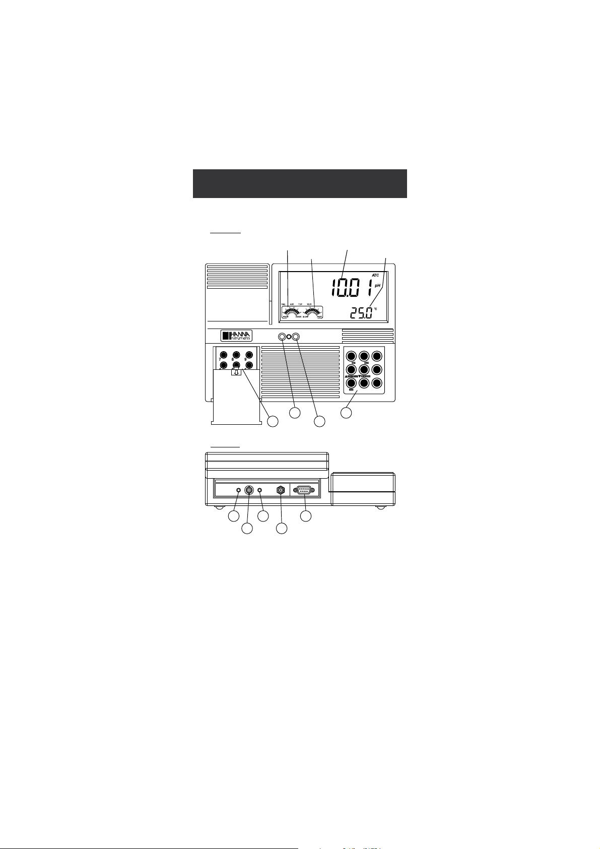
FUNCTIONAL DESCRIPTION
NUMReso
RelmVmVpH
AutoLOG
SETGLPAutoHOLD
ON OFF
Front Panel
Rear Panel
1
2
3
4
Primary LCD
Secondary LCD
Electrode Condition
5
6
7
8
9
Electrode Response
RS232POWERTEMPpH/ORPPIN
Calibration Check
RCL
LOG
MODE
CLR
CFMCAL
pH / mV Meter
HI 120
HI 120
1) Left Keyboard
2) ON switch
3) OFF switch
4) Right Keyboard
5) Pin input socket
6) BNC electrode connector
7) Temperature probe socket
8) Power adapter socket
9) RS232 serial communication connector
4
Page 5
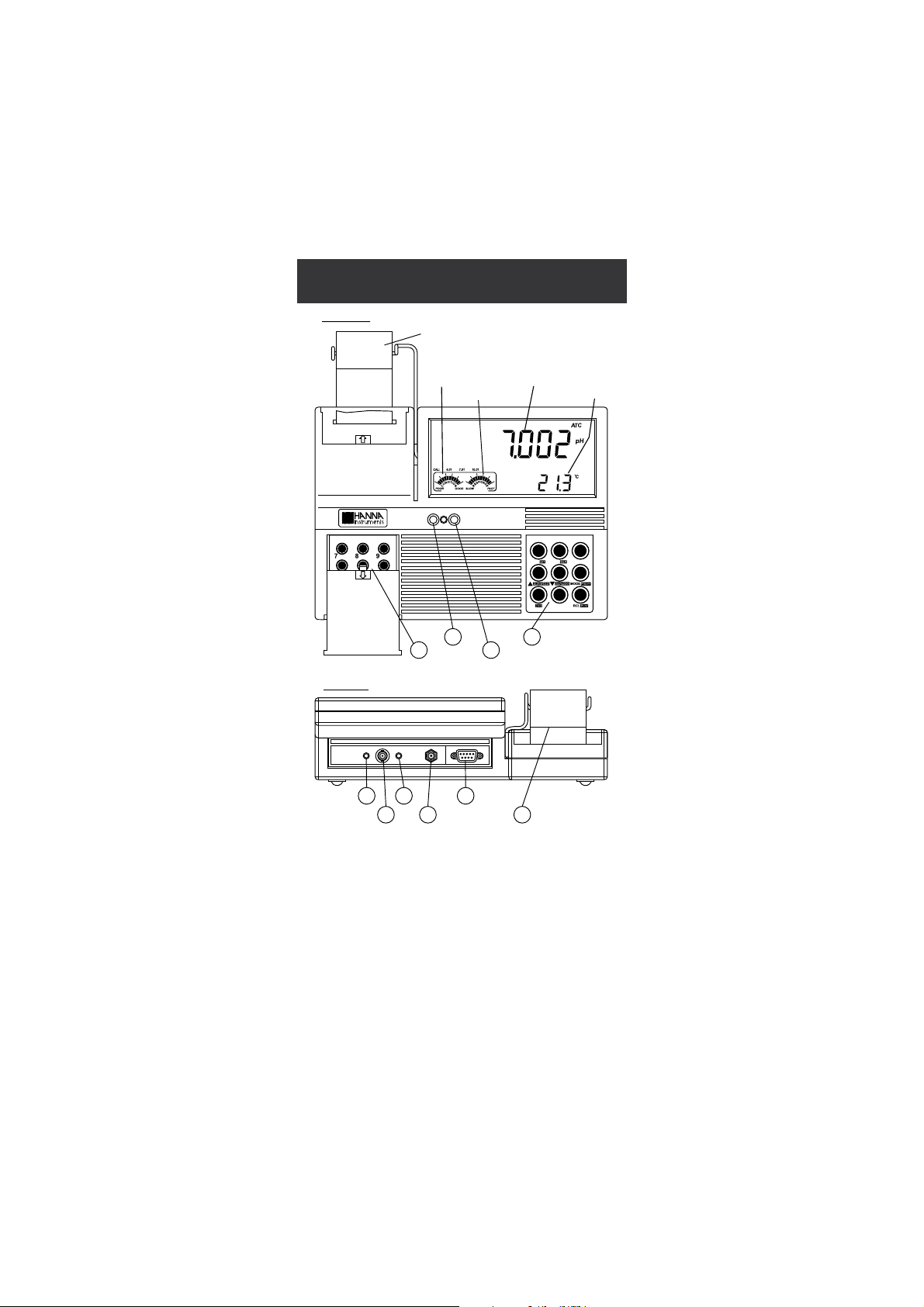
FUNCTIONAL DESCRIPTION
ON OFF
NUMReso
RelmVmVpH
AutoLOG
PaperPrintAutoHOLD
1
2
3
4
Front Panel
Primary LCD
Secondary LCD
Electrode Condition
Electrode Response
Rear Panel
567
8
9
10
Paper Roll
RS232POWERTEMPpH/ORPPIN
Calibration Check
LOG
CLR
CFMCAL
pH / mV Meter
HI 122
HI 122
1) Left Keyboard
2) ON switch
3) OFF switch
4) Right Keyboard
5) Pin input socket
6) BNC electrode connector
7) Temperature probe socket
8) Power adapter socket
9) RS232 serial communication connector
10) Printer
5
Page 6
HI 120
1 2
3
4
5
10 11 12
7
6
9
8
NUMResolution
RelmVmVpH
AutoLOG
SETGLPAutoHOLD
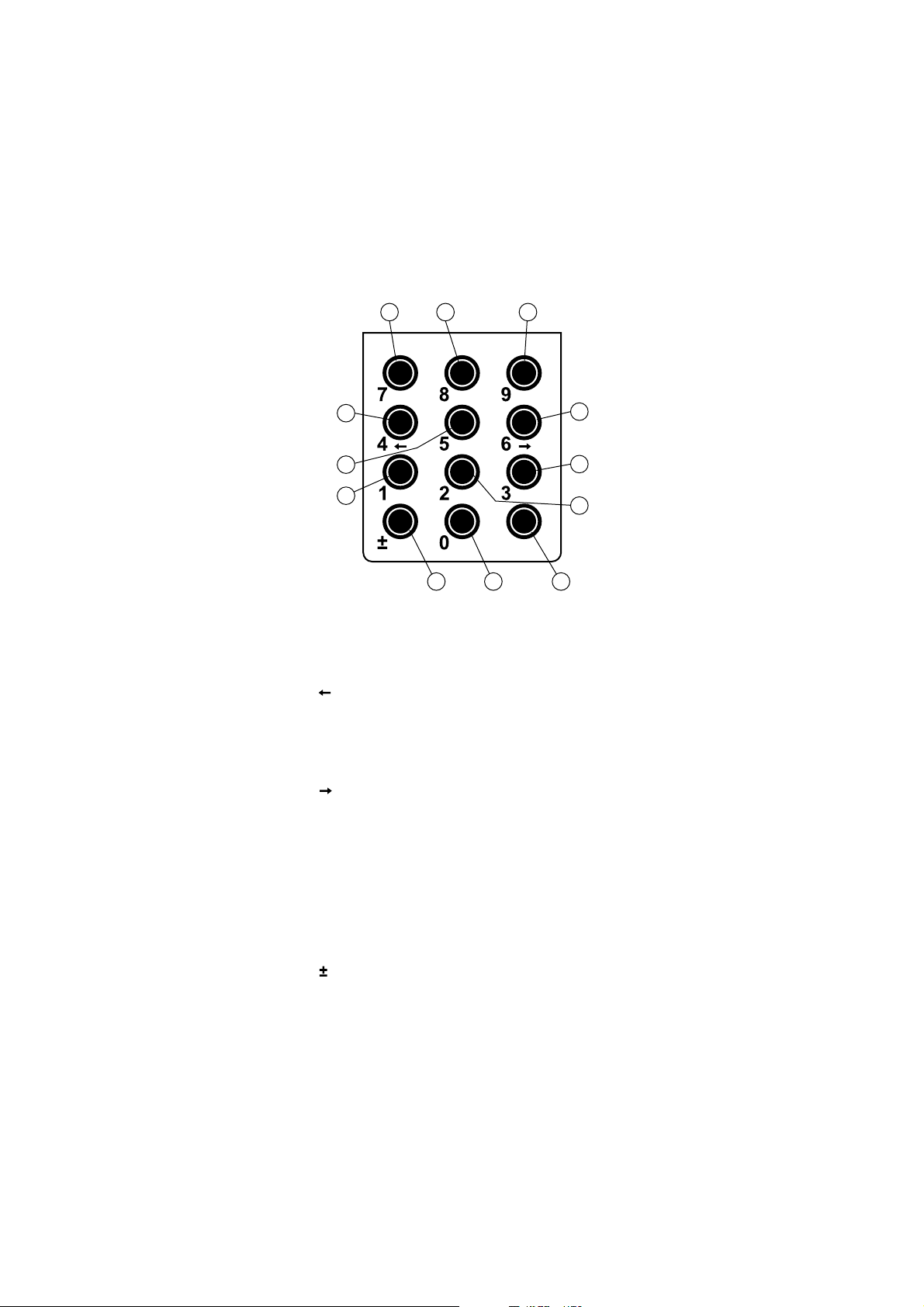
KEYBOARD ON THE LEFT
Shortcuts to alternate functions
1) AutoHOLD key, to freeze the first stable reading on the LCD.
2) GLP key, to display Good Laboratory Practice Information.
3) SET key, to enter/exit SETUP mode.
4) key, to toggle between parameters while in RECALL or SETUP
modifying mode (backwards), to toggle between absolute mV and
temperature while in Relative mV mode and between pH buffer and
temperature while in pH calibration mode.
5) AutoLOG key, to start/stop AutoLOG mode.
6) key, to toggle between parameters while in RECALL or SETUP
modifying mode (forwards), to toggle between absolute mV and
temperature while in Relative mV mode and between pH buffer and
temperature while in pH calibration mode.
7) pH key, to select pH range.
8) mV key, to select mV range.
9) RelmV key, to select Relative mV range.
11) Resolution key, to select pH resolution.
Numerical keys
10) key, to change sign.
12) NUM key, to activate the numerical keys (0 to 9).
6
Page 7
HI 120
1
9
8
7
6
5
4
3
2
Calibration Check
RCL
LOG
MODE
CLR
CFMCAL
pH / mV Meter
HI 120
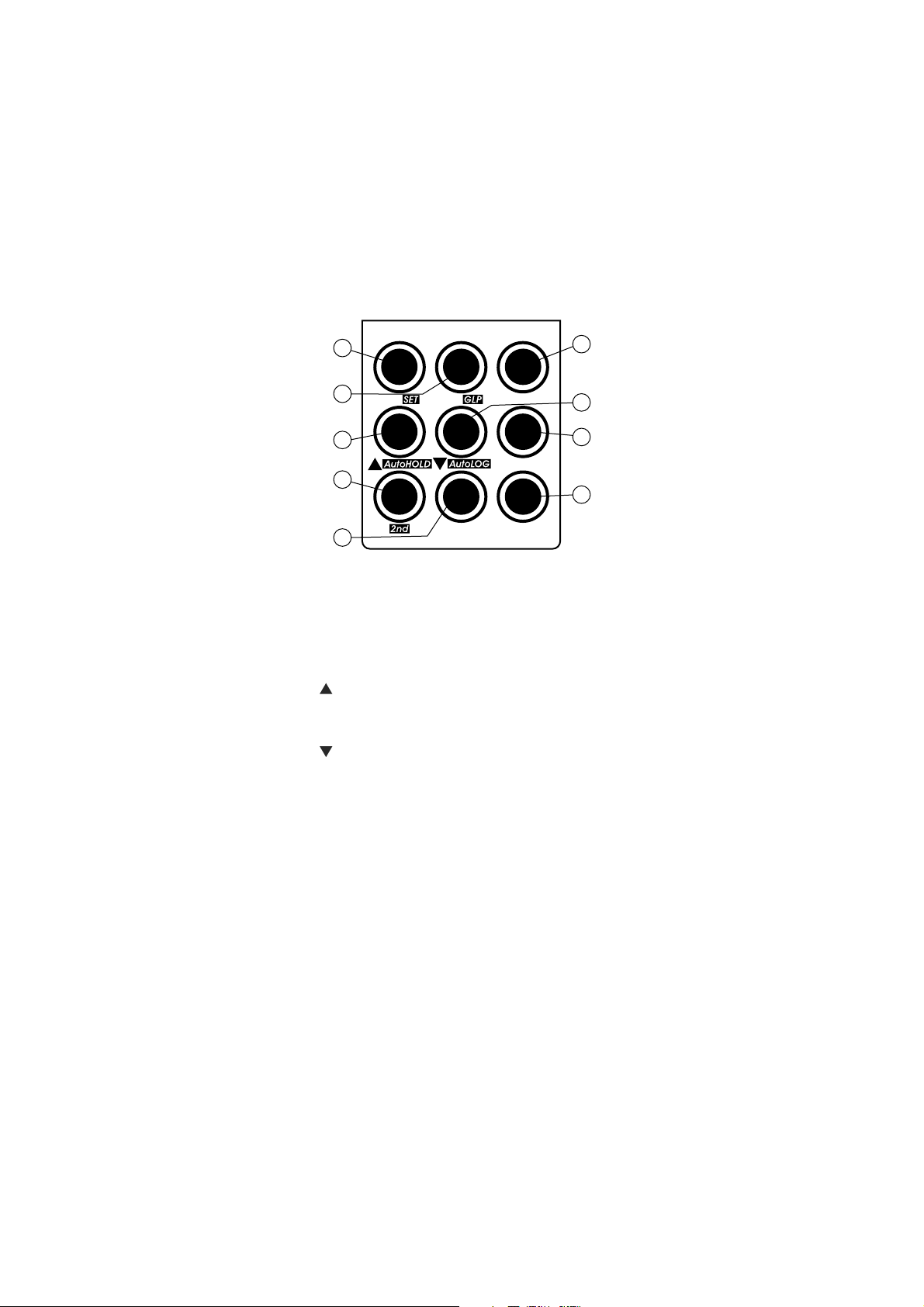
MAIN KEYBOARD ON THE RIGHT
1) CAL key, to enter and exit/escape calibration mode.
SET key (second function), to enter/exit SETUP mode.
2) CFM key, to confirm different values.
GLP key (second function), to display Good Laboratory Practice Information.
3) CLR key, to clear calibration or logged data.
4) key, to manually increase temperature value or other parameters.
AutoHOLD key (second function), to freeze the first stable reading on
the LCD.
5) key, to manually decrease temperature value or other parameters.
AutoLOG key (second function), to start/stop AutoLOG mode.
6) MODE key, to select the measurement unit or to switch focused data.
7) 2nd key, to select second key function.
8) LOG key, to store measured data.
9) RCL key, to enter/exit view logged data mode.
Note: To select second key function, press 2nd and then the desired key.
The “2nd” tag will appear on the LCD until the desired key is
pressed. To leave second key function selection, press 2nd again.
7
Page 8

HI 122
1 2
3
4
5
10 11 12
7
6
9
8
NUMResolution
RelmVmVpH
AutoLOG
PaperPrintAutoHOLD
KEYBOARD ON THE LEFT
Shortcuts to alternate functions
1) AutoHOLD key, to freeze the first stable reading on the LCD.
2) Print key, to obtain a printout or to cancel printing.
3) Paper key, to pull out the paper.
4) key, to toggle between parameters while in RECALL or SETUP
modifying mode (backwards), to toggle between absolute mV and
temperature while in Relative mV mode and between pH buffer and
temperature while in pH calibration mode.
5) AutoLOG key, to start/stop AutoLOG mode.
6)
key, to toggle between parameters while in RECALL or SETUP
modifying mode (forwards), to toggle between absolute mV and
temperature while in Relative mV mode and between pH buffer and
temperature while in pH calibration mode.
7) pH key, to select pH range.
8) mV key, to select mV range.
9) RelmV key, to select Relative mV range.
11) Resolution key, to select pH resolution.
Numerical keys
10) key, to change sign.
12) NUM key, to activate the numerical keys (0 to 9).
8
Page 9
HI 122
9
8
7
6
5
4
3
2
1
Calibration Check
LOG
CLR
CFMCAL
pH / mV Meter
HI 122
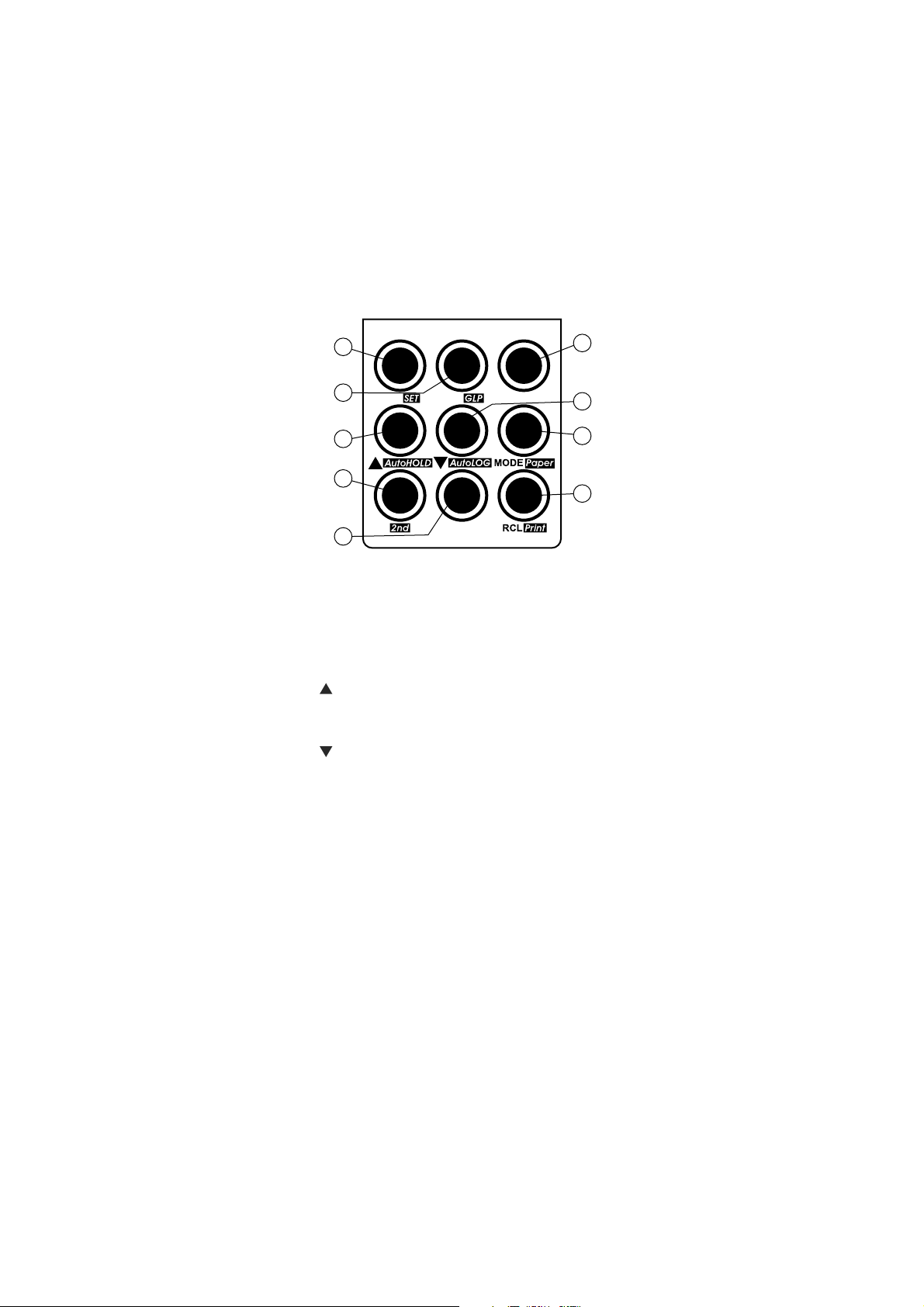
MAIN KEYBOARD ON THE RIGHT
1) CAL key, to enter and exit/escape calibration mode.
SET key (second function), to enter/exit SETUP mode.
2) CFM key, to confirm different values.
GLP key (second function), to display Good Laboratory Practice Information.
3) CLR key, to clear calibration or logged data.
4) key, to manually increase temperature value or other parameters.
AutoHOLD key (second function), to freeze the first stable reading on
the LCD.
5) key, to manually decrease temperature value or other parameters.
AutoLOG key (second function), to start/stop AutoLOG mode.
6) MODE key, to select the measurement unit or to switch focused data.
Paper key (second function), to pull out the paper.
7) 2nd key, to select second key function.
8) LOG key, to store measured data.
9) RCL key, to enter/exit view logged data mode.
Print key (second function), to obtain a printout or to cancel printing.
Note: To select second key function, press 2nd and then the desired key.
The “2nd” tag will appear on the LCD until the desired key is
pressed. To leave second key function selection, press 2nd again.
9
Page 10

EGNAR
– Hp00.61ot00.2
– Hp000.61ot000.2
Vm9.999±
Vm0002±
)Fº0.842ot0.4–(Cº0.021ot0.02–
NOITULOSER
Hp10.0
Hp100.0
Vm1.0
Vm1
)Fº1.0(Cº1.0
YCARUCCA
F°86/C°02@
Hp10.0±
Hp200.0±
)Vm9.996±(Vm2.0±
)Vm9.999±(Vm5.0±
)Vm0002±(Vm1±
)Fº7.0±(Cº4.0±
)rorreeborpgnidulcxe(
egnartesffoVmevitaleR Vm0002±
noitarbilaCHp
,noitarbilactniop-evifotpU
elbaliavasreffubdradnats7
0.7,68.6,10.4,86.1( ,)54.21,10.01,81.9,1
sreffubmotsuc2dna
noitasnepmocerutarepmeT
:morfcitamotuArolaunaM
)Fº0.842ot0.4–(Cº0.021ot0.02–
edortcelEHp P1311IH
eborperutarepmeT 2667IH
lavretnIgniggoL setunim081otsdnoces5
)ylno221IH(retnirP repapediwmm44,xirtamtoD
ecafretniCP 232SRdetalosi-otpo
ecnadepmitupnI 01
21
mho
ylppusrewoP retpadaCDV21
snoisnemiD )”3.3x0.8x0.11(mm48x302x082
thgieW )bl2.4(gK9.1:retnirphtiwtik;)bl1.4(gK8.1
tnemnorivnE
)Fº221–23(Cº05–0
gnisnednoc-nonHR%59.xam
ytnarraW sraey2
HI 120 AND HI 122
SPECIFICATIONS
10
Page 11
OPERATIONAL GUIDE
POWER CONNECTION
Plug the 12 VDC adapter into the power supply socket.
Notes: • These instruments use non volatile memory to retain the pH,
mV, temperature calibrations and all other settings, even
when unplugged.
• Make sure a fuse protects the main line.
ELECTRODE AND PROBE CONNECTIONS
For HANNA P type pH or ORP electrodes (with internal reference) connect the
electrode’s BNC to the socket on the back of the instrument (#6 on page 4
and 5) and the pin to the appropiate socket (#5 on page 4 and 5).
Notes: • Electrode condition and response information is displayed on the
bar graph gauges during the day the calibration is performed
only if HANNA P type (PIN) electrodes are used.
• If the electrode is not recognized as a HANNA P type electrode,
the bar graph gauges will blink (25 seconds OFF, 4 seconds ON,
full bar graph).
For temperature measurements and automatic temperature compensation,
connect the temperature probe to the appropriate socket.
INSTRUMENT START-UP
• Turn the instrument on by pressing the ON switch.
• All LCD tags are displayed and a beep is heard while the instrument
performs a self test.
• The instrument displays then the date on the primary LCD and the
time on the secondary LCD, along with the “Remove protective cap”
and “Unscrew electrode refilling cap” messages alternatively blinking.
These messages alert the user to follow displayed instructions in order
to take proper measurements and to improve electrode response.
• The instrument automatically defaults to pH or mV measurement
mode, if a HANNA P type pH or ORP electrode is detected.
• If no HANNA P type electrode is detected, the instrument starts in the
same range as it was at power off.
11
Page 12
pH MEASUREMENTS
Make sure the instrument has been calibrated before
taking pH measurements.
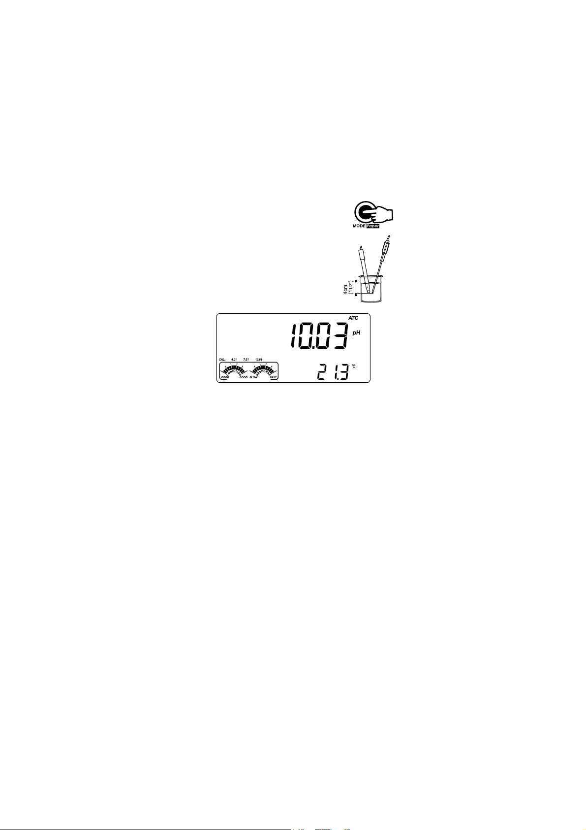
• Press MODE to enter pH mode.
Note: To change pH resolution, press MODE again or
simply Resolution from the left keyboard.
• Submerge the electrode tip and the temperature
probe approximately 4 cm (1½”) into the sample to
be tested. Allow time for the electrode to stabilize.
• The pH is displayed on the primary LCD and the
temperature on the secondary LCD.
OUT CAL RANGE feature warns the user if the current reading is out of the
calibrated area. The calibrated area is that part of the pH range in which
the calibration point assures an accurate reading. If the reading is taken out
of the calibration area, the “OUT CAL RANGE” message will blink. The
calibrated area is calculated in according with the pH resolution used during
the reading. To avoid having this message, the calibration points have to be
well distributed in the desired measurement range.
If measurements are taken successively in different samples, it is recommended
to rinse the electrode thoroughly with deionized water or tap water and then
with some of the next sample to prevent cross-contamination and to condition
the electrode before immersing it into the sample solution.
The pH reading is affected by temperature. In order to measure the pH
accurately, the temperature effect must be compensated for. To use the
Automatic Temperature Compensation feature, connect and submerge
the HI 7662-T temperature probe into the sample as close as possible to the
electrode and wait for a few seconds.
If the temperature of the sample is known, manual temperature
compensation can be performed by disconnecting the temperature probe.
The display will then show the default temperature of 25 ºC (77 ºF) or the
last temperature reading with the “ºC” (or “ºF”) tag blinking. The
temperature can be adjusted with the ARROW keys or the numerical
keypad (from –20.0 ºC to 120.0 ºC or from –4.0 ºF to 248.0 ºF).
12
Page 13
Press NUM to change the temperature value with the numerical keys. The
“2nd” tag will blink. Press CLR if you want to delete digits of the
displayed value. The remaining digits will shift to right. Introduce the
desired value. If the value is out of temperature range, a long beep will
be heard. Press NUM to confirm the new value or CAL to escape without
changing the temperature.
mV/ORP MEASUREMENTS
Oxidation-reduction potential (REDOX) measurements provide the quantification
of the oxidizing or reducing power of the tested sample.
To correctly perform a redox measurement, the surface of the ORP electrode
must be clean and smooth.
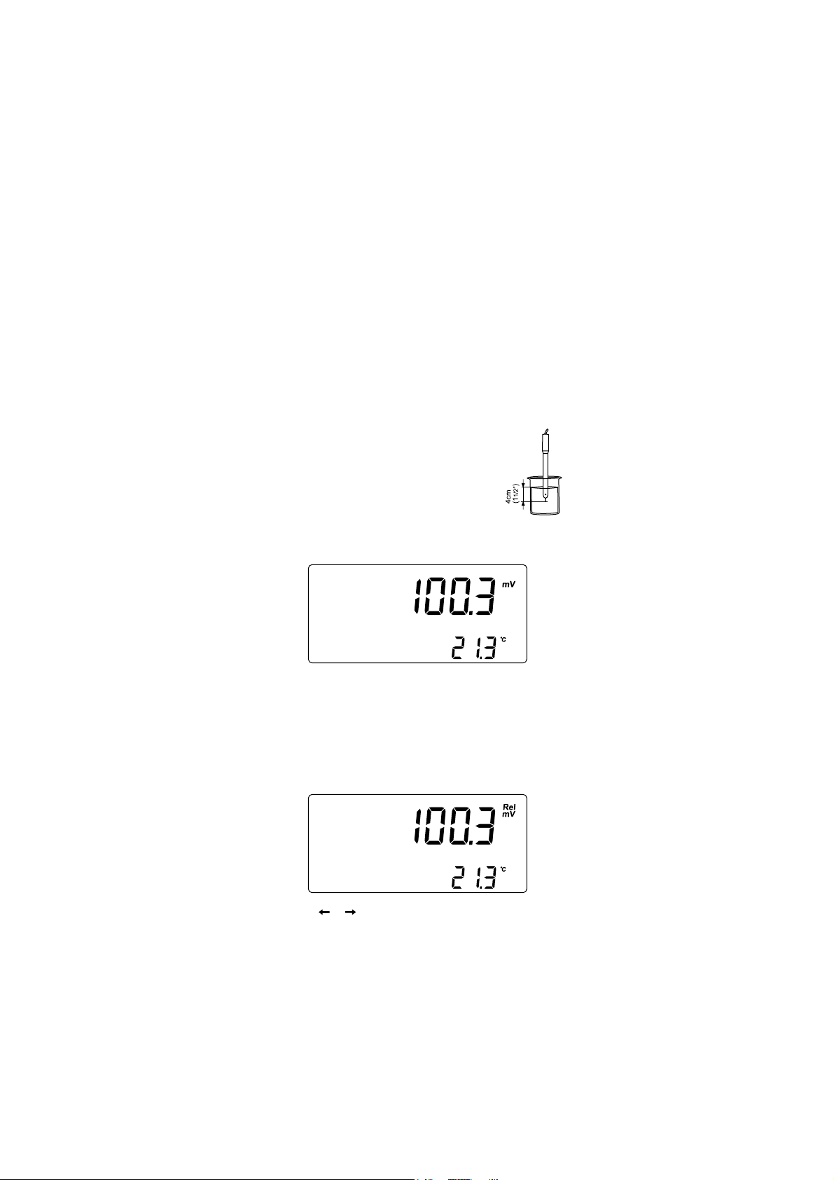
• Press MODE or simply mV from the left keyboard to
enter mV range.
• Submerge the tip of the ORP electrode (4 cm/1½”)
into the sample to be tested and allow a few
seconds for the reading to stabilize.
• The instruments display the mV reading on the primary LCD and the
temperature on the secondary LCD.
• If the reading is out of range, the closest full-scale value will be
displayed blinking on the primary LCD.
RELATIVE mV MEASUREMENTS
To enter Relative mV mode, press MODE or simply RelmV from the left
keyboard. The relative mV reading will be displayed on the primary LCD and
the current temperature value on the secondary LCD.
Note: Press or from the left keypad to toggle between temperature
and absolute mV reading on the secondary LCD.
13
Page 14

The Relative mV reading is equal to the difference between the absolute
mV input value and relative mV offset established in the relative mV
calibration.
TEMPERATURE MEASUREMENTS
Connect the HI 7662-T temperature probe to the appropri-
ate socket. Immerse the temperature probe into the sample
and allow the reading on the secondary LCD to stabilize.
Note: The temperature can be displayed in Celsius degrees (ºC) or in
Fahrenheit degrees (ºF) (see SETUP for details, page 27).
14
Page 15

pH CALIBRATION
Calibrate the instrument often, especially if high accuracy is required.
The instrument should be recalibrated:
• Whenever the pH electrode is replaced.
• At least once a week.
• After testing aggressive chemicals.
• If “CAL DUE” tags are blinking during measurement.
• If “OUT CAL RANGE” message blinks during pH measurement (the
measurement range is not covered by current calibration).
PREPARATION
Pour small quantities of the buffer solutions into clean beakers. If possible,
use plastic or glass beakers to minimize any EMC interferences.
For accurate calibration and to minimize cross-contamination, use two beakers
for each buffer solution. One for rinsing the electrode and one for calibration.
If you are measuring in the acidic range, use pH 7.01 or 6.86 as first buffer
and pH 4.01 or 1.68 as second buffer. If you are measuring in the alkaline range,
use pH 7.01 or 6.86 as first buffer and pH 10.01/9.18 or 12.45 as second buffer.
For extended range measurements (acidic and alkaline), perform a five-point
calibration by selecting five of the available buffers.
PROCEDURE
If 0.001 pH resolution is selected, each selected standard buffer value can
be updated in according with the value on the production lot certificate at
25 ºC (77 ºF). Press 2nd then SET key when a standard pH buffer with
0.001 resolution is selected. The buffer value will start blinking and it can
be changed with the ARROW keys in a ±0.020 pH window.
Calibration has a choice of 7 memorized buffers: pH 1.68, 4.01, 6.86,
7.01, 9.18, 10.01, 12.45 and 2 custom buffers.
The custom buffers are a special option that allows the user to calibrate in
a buffer solution different from a standard one. Up to two custom buffers
can be set in SETUP menu (see page 27). When selected during
calibration, the “CUSTOM C1” or “CUSTOM C2” tags are displayed on the
LCD and the custom buffer value can be changed in a ±1.0 pH window,
around the set value.
For accurate measurements it is recommended to perform a five-point
calibration. However, at least a two-point calibration is suggested.
The instruments will automatically skip the buffers used during calibration
and the buffers which are in a ±0.2 pH window, around one of the
calibrated buffers.
15
Page 16
All new calibrations will override existing stored calibration data, in a ±0.2
CAL
pH window, at these calibration points. The slopes adjacent to the calibration
points will be reevaluated.
If the new calibration point has no correspondence in the existing stored
calibration data, it is added to it if this is not full, or the instrument will
ask which buffer will be replaced by the current buffer.
If at least a two-point calibration has been performed and an offset
correction of the electrode is desired, keeping unchanged the existing
slopes, perform a one-point calibration with “OFFS” option selected in
SETUP menu. If “Pnt” option is selected, the slopes adjacent to the
calibration points will be reevaluated.
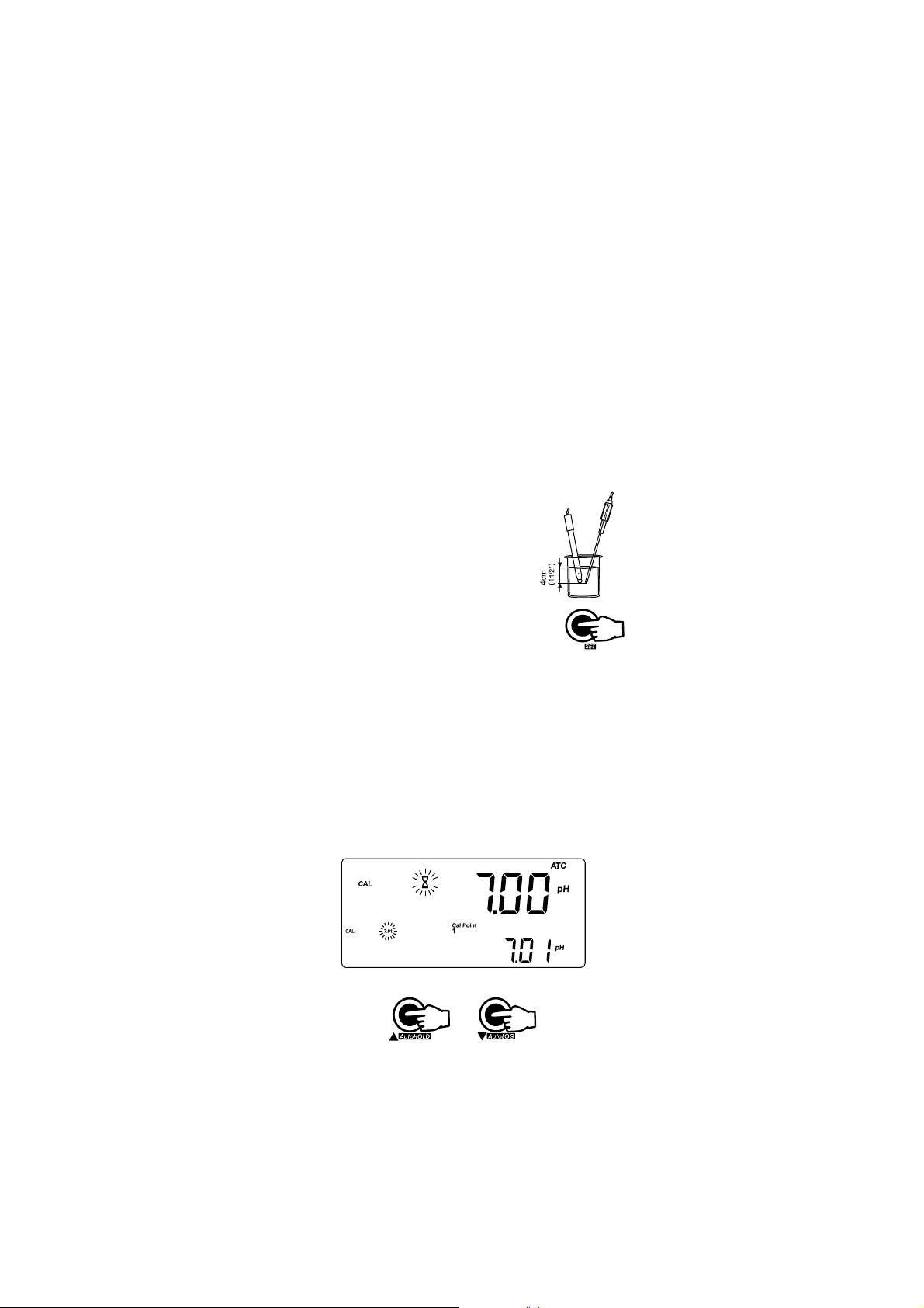
FIVE-POINT CALIBRATION
• Immerse the pH electrode and the temperature
probe approximately 4 cm (1½”) into a buffer
solution of your choice (pH 1.68, 4.01, 6.86, 7.01,
9.18, 10.01, 12.45, custom buffer 1 or 2, if these
were set) and stir gently. The temperature probe
should be close to the pH electrode.
• Press CAL. The “CLEAR CAL IF NEW ELECTRODE”
message will be displayed blinking on the LCD for a
few seconds if the instrument was calibrated before
and calibration was not cleared.
Press CLR if you are using a new electrode or want to clear calibration
history, or wait a few seconds to continue.
Press CAL again or the ARROW keys to skip this message.
Note: It is very important to clear calibration history when a new
electrode is used because most errors and warning messages
that appear during calibration depend on calibration history.
• The instruments will display the measured pH on the primary LCD and
the “7.01” buffer on the secondary LCD, together with “CAL” and “Cal
Point 1” tags and “7.01” tag blinking.
• If necessary, press the ARROW keys to select a different buffer value.
16
Page 17
• The “ ” tag will blink on the LCD until the reading is stable.
CFM
CFM
CFM
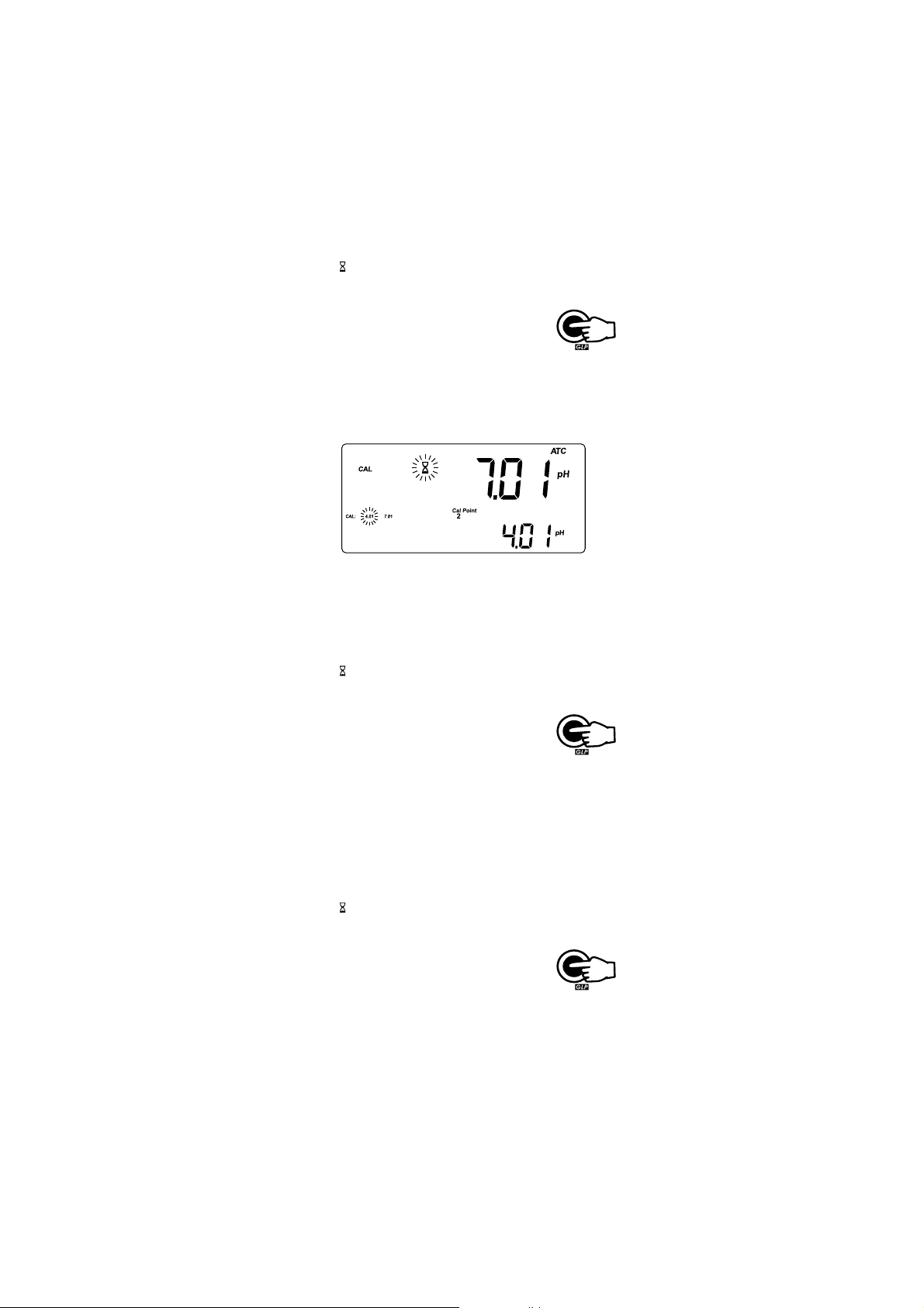
• When the reading is stable and close to the selected
buffer, “CFM” tag blinks.
• Press CFM to confirm calibration.
• The calibrated value is then displayed on the primary
LCD and the secondary LCD will display the second
expected buffer value, together with “CAL”, “Cal
Point 2” and “7.01” tags and the corresponding
buffer tag blinking.
• After the first calibration point is confirmed, immerse the pH electrode and
the temperature probe approximately 4 cm (1½”) into the second buffer
solution and stir gently. The temperature probe should be close to the pH
electrode.
• If necessary, press the ARROW keys to select a different buffer value.
• The “ ” tag will blink on the LCD until the reading is stable.
• When the reading is stable and close to the selected
buffer, “CFM” tag blinks.
• Press CFM to confirm calibration.
• The calibrated value is then displayed on the
primary LCD and the secondary LCD will display the
third expected buffer value.
• After the second calibration point is confirmed, immerse the pH
electrode and the temperature probe approximately 4 cm (1½”) into
the third buffer solution and stir gently. The temperature probe should
be close to the pH electrode.
• If necessary, press the ARROW keys to select a different buffer value.
• The “ ” tag will blink on the LCD until the reading is stable.
• When the reading is stable and close to the selected
buffer, “CFM” tag blinks.
• Press CFM to confirm calibration.
• The calibrated value is then displayed on the
primary LCD and the secondary LCD will display the
fourth expected buffer value.
17
Page 18

CFM
CFM
• After the third calibration point is confirmed, immerse the pH electrode and the
temperature probe approximately 4 cm (1½”) into the fourth buffer solution
and stir gently. The temperature probe should be close to the pH electrode.
• If necessary, press the ARROW keys to select a different buffer value.
• The “ ” tag will blink on the LCD until the reading is stable.
• When the reading is stable and close to the selected
buffer, “CFM” tag blinks.
• Press CFM to confirm calibration.
• The calibrated value is then displayed on the
primary LCD and the secondary LCD will display the
fifth expected buffer value.
• After the fourth calibration point is confirmed, immerse the pH
electrode and the temperature probe approximately 4 cm (1½”) into
the fifth buffer solution and stir gently. The temperature probe should
be close to the pH electrode.
• If necessary, press the ARROW keys to select a different buffer value.
• The “ ” tag will blink on the LCD until the reading is stable.
• When the reading is stable and close to the selected
buffer, “CFM” tag blinks.
• Press CFM to confirm calibration.
• The instruments store the calibration values and
return to normal measurement mode.
FOUR, THREE or TWO-POINT CALIBRATION
• Proceed as described in “FIVE-POINT CALIBRATION” section.
• Press CAL after the appropriate accepted calibration point. The instruments
will return to measurement mode and will memorize the calibration data.
ONE-POINT CALIBRATION
Two SETUP selectable options are available: “Pnt” and “OFFS”.
If the “Pnt” option is selected, the adjacent slopes will be reevaluated.
If the “OFFS” option is selected, an electrode offset correction is performed
keeping unchanged the existing slopes.
• Proceed as described in “FIVE-POINT CALIBRATION” section.
• Press CAL after the first calibration point was confirmed. The instruments
will memorize the one-point calibration data and will return to measurement mode.
Notes: • Press MODE or / from the left keyboard to toggle between
pH buffer and temperature reading during calibration.
• Each time a buffer is confirmed, the new calibration parameters
replace the old calibration parameters of the corresponding buffer.
If current confirmed buffer has no correspondence in the existing
stored calibration and this is not full, the current buffer is added
to the existing stored calibration.
18
Page 19

If the existing stored calibration is full (five calibration points), the
instrument asks which buffer will be replaced by current buffer.
Press the ARROW keys to select another buffer to be replaced.
Press CFM to confirm the buffer that will be replaced.
Press CAL to leave calibration without replacing.
Note: The replaced buffer is not removed from calibration list and it can
be selected for the next calibration points.
WORKING WITH CUSTOM BUFFERS
If at least one custom buffer was set in SETUP menu, it can be selected for
calibration by pressing the ARROW keys. Press 2nd then SET key if you
want to adjust the buffer value. The buffer value, displayed on the
secondary LCD, will start blinking.
Use the ARROW keys to change the buffer value.
After about 5 seconds you performed the last change, the buffer value is
updated. Press 2nd then SET key if you want to change it again.
Note: Custom buffer value can be adjusted in a ±1.00 pH window, around
the set value.
CLEAR CALIBRATION
Press CLR in any moment during calibration. The “CLEAR CAL” tag will
appear and “donE” message will be displayed on the secondary LCD.
All old calibrations, starting with current selected buffer are cleared and
the instrument continues calibration.
If CLR is pressed when “CLEAR CAL IF NEW ELECTRODE” message is
displayed blinking, the calibration history is deleted and the instrument
will display “hiSt” message on the primary LCD and “donE” message on
the secondary LCD, along with “CLEAR CAL” tags. The calibration process
will continue starting with 7.01 pH buffer as first buffer.
Note: If CLR is pressed during the first calibration point, the instrument
returns to measurement mode.
19
Page 20

ENHANCED CALIBRATION MESSAGES
The stored calibration history to used issue error and warning messages
during calibration to help ensure the highest accuracy.
As electrode aging is normally a slow process, substantial changes from
previous calibrations are likely due to a temporary problem with the electrode
or buffers. Calibrating under these conditions will result measurement errors.
ERROR MESSAGES
Error messages appear if one or all of the calibration parameters are out
of accepted windows. When these messages are displayed, calibration
cannot be confirmed.
WRONG BUFFER
This message appears when the difference between the pH reading and
the value of the selected buffer is too big. If this error message is displayed,
check if you have selected the proper calibration buffer.
WRONG BUFFER TEMPERATURE
This message appears if the temperature of the buffer is outside the
defined buffer temperature range.
WRONG & CONTAMINATED BUFFER / CHECK ELECTRODE
This message appears if the buffer used is contaminated or the electrode is
supposed to be either broken or very dirty.
WRONG & CHECK ELECTRODE / CLEAN ELECTRODE
This message appears if the electrode is supposed to be broken or very dirty.
WRONG & OLD / CLEAR CAL & OLD
This message appears as a result of an erroneous slope condition. If the
slope between current calibration point and one of the previous calibration,
that was not overriden in current calibration, exceeds slope window (80%
to 110%), this message will appear. Press CLR to clear old parameters
and continue calibration process or CAL to leave calibration.
WARNING MESSAGES
During calibration, the Calibration Check feature analyzes the electrode
calibration history and warns the user when problems have been detected. It
is possible to override the warning messages and confirm the calibration but
it is not recommended.
CLEAR CAL IF NEW ELECTRODE
This warning is displayed any time you enter calibration and calibration is not
cleared or the new calibration parameters are better than the previous ones.
You can clear calibration history by pressing CLR, or continue by pressing CAL.
20
Page 21

CLEAN ELECTRODE
This warning message appears in order to alert the user that some dirt or
deposits could be on the electrode. Refer to the electrode Cleaning Procedure.
This ensures the removal of film, dirt or deposits on the glass bulb and
reference junction.
CONTAMINATED BUFFER
This warning message appears in order to alert that the buffer could be
contaminated. Refresh your buffer and continue the calibration procedure.
CHECK ELECTRODE / CHECK BUFFER
This warning message appears when the electrode slope exceeds the highest
accepted slope limit (110%). Check your electrode and use fresh buffers.
CLEAN ELECTRODE / CHECK BUFFER
This warning appears in order to alert the user that the electrode can be
dirty or the buffer contaminated. Refer to the electrode Cleaning Procedure
and use fresh buffers.
ELECTRODE CONDITION &
ELECTRODE RESPONSE TIME
When using an appropriate HANNA BNC electrode with pin, the instrument
will assess electrode condition and response time during each calibration and
will display the calibration status for the rest of the day.
The digital gauge for electrode condition is a representation of the offset
and slope performance of the electrode. The response gauge is a function
of the stabilization time between the first and second calibration buffers.
These gauges reflect electrode performance and should be expected to
slowly decrease over the life of the electrode.
The condition and response gauges show the electrode’s condition at the
time of calibration only and are displayed for the rest of the day the
calibration is performed. For a continuous display of electrode condition at
the time of calibration, daily calibration is necessary. The electrode
condition and response time are also visible when viewing GLP data.
If the instrument is not calibrated, it has been calibrated only in one
point, or if calibration history was deleted, the electrode condition and
response gauges will be empty.
21
Page 22

The electrode response is evaluated only when calibration has been
performed using pH 7.01 or pH 6.86, pH 4.01 and pH 10.01 or pH 9.18
buffers. When the instrument cannot evaluate the electrode response or pH
1.68/12.45 buffer was used as calibration buffer, the response gauge will
be empty.
If the electrode is in a very poor condition, the first condition segment will blink.
If the electrode response is very slow, the first response segment will blink.
RELATIVE mV CALIBRATION
• Press CAL when the instrument is in RELATIVE mV measurement mode.
The relative mV value is displayed on the primary LCD and the absolute
mV value on the secondary LCD.
• Use the ARROW keys or the numerical keys if you want to change the
displayed relative mV value.
Notes: • Press MODE to select another resolution if the displayed value
allows it (e.g. if 199.9 is displayed, by pressing MODE the
value will change to 1999; if 19.9 is displayed, nothing will
happen if pressing MODE).
• Pressing CLR the displayed value is set to 0.0 mV.
• Press NUM from the left keyboard if you want to change the
value using the numerical keys. The “2nd” tag will blink.
• Press CLR to delete the last digit.
• Press MODE to select another resolution (see above).
• Press NUM again to leave the numerical keyboard.
• When the reading is stable, in mV range and the Relative mV offset is
inside the offset window (±2000 mV), “CFM” tag blinks.
• Press CFM to confirm relative mV calibration. The instrument will
return to measurement mode.
• If the absolute mV reading is out of range or the Relative mV offset is
out of the offset window, “WRONG” tag will blink. Change the input
value or the Relative mV offset to complete the calibration process.
22
Page 23

GOOD LABORATORY PRACTICE (GLP)
GLP is a set of functions that allows storage and retrival of data regarding
the maintenance and status of the electrode.
All data regarding pH and Rel mV calibration is stored for the user to
review when necessary.
CALIBRATION ALARM TIME OUT
For pH calibration, all the instruments allow the user to set the number of
days before the next required pH calibration. This value can be set from 1
to 7 days. The default setting is OFF (disabled).
The instrument checks if the time-out has expired. If the time elapsed,
“CAL DUE” tags will blink as a reminder.
Note: If the instrument was not calibrated or all calibration parameters
were cleared, “CAL” “DUE” tags will be displayed even if the feature
is disabled in SETUP menu.
LAST pH CALIBRATION DATA
The last pH calibration data is stored automatically after a successful
calibration.
To view the pH calibration data, press 2nd then GLP key or simply GLP from the
left keyboard (HI 120) when the instrument is in pH (mV) measurement mode.
The instrument will display the date (yyyy.mm.dd) of the last calibration.
Press the ARROW keys to view the next calibration parameter (pressing
the key):
• The time (hh:mm) of the last calibration.
23
Page 24

• The pH calibration offset.
• The pH calibration slope (the GLP slope is the average of the calibration
slopes; the percentage is referred to the ideal value of 59.16 mV/pH).
• The calibration buffers in calibrating order, with the corresponding
warnings.
The first pH calibration buffer:
The second pH calibration buffer:
The third pH calibration buffer:
24
Page 25

The fourth pH calibration buffer:
The fifth pH calibration buffer:
Notes: • The “OLd” message displayed beside the pH value means that
this buffer was not used during last calibration. Press 2nd then
SET key if you want to see calibration date (or time, if old
calibration was performed in the same day with current calibration).
• Each calibration buffer is displayed with the resolution from
calibration moment.
• If “no bUF” message appears on the LCD, the instrument informs
you that calibration was performed in less than five points.
• The Calibration Alarm Time Out status.
If disabled,
or the number of days until the calibration alarm will be displayed
(e.g. 5 days), or from the time calibration expired (e.g. –3 days).
• The instrument ID.
25
Page 26

LAST RELATIVE mV CALIBRATION DATA
Last Relative mV calibration data is stored automatically after a successful
calibration.
To view the Relative mV calibration data, press 2nd then GLP key or simply
GLP from the left keyboard (HI 120) while in Relative mV measurement mode.
The instrument will display the Relative mV GLP information.
• The date (yyyy.mm.dd) of the last calibration as in pH GLP mode.
Press the ARROW keys to view the next logged calibration parameter
(pressing the key):
• The Relative mV calibration offset and time (hh:mm) as in pH GLP mode.
• The instrument ID as in pH GLP mode.
Notes: • Press 2nd then GLP key at any moment and the instrument
will return to measurement mode.
• If calibration has not been performed, the instrument displays
“no CAL” message blinking.
26
Page 27

SETUP
Setup mode allows viewing and modifying the following parameters:
• Calibration Alarm Time Out
• One-point calibration behaviour
• Custom Buffer 1
• Custom Buffer 2
• Alarm High Limit
• Alarm Low Limit
• AutoLOG Start Condition
• AutoLOG End Condition
• AutoLOG Interval
• Temperature Unit
• Current Date (yyyy.mm.dd)
• Current Time (hh:mm)
• Printing Language (HI 122 only)
• Printer Status (HI 122 only)
• Beep Status
• Baud Rate (serial communication)
• Command prefix (serial communication)
• Instrument ID
To enter SETUP mode, press 2nd then SET key, or simply SET from the left
keyboard (HI 120 only), while the instrument is in measurement mode.
Select the desired setup parameter using the ARROW keys.
Press CAL if you want to change the item value. The selected item (e.g.
hour, in setting up the correct time) and “CFM” tag will start blinking.
Press the ARROW keys to change the displayed value or simply use the
numerical keys for all numerical parameters.
Note: To use the numerical keys, press NUM from the left keyboard. The “2nd”
tag will blink. Set the desired number digit by digit. The new introduced
digit is always the last one. All the previous digits will shift to left.
To delete digits press CLR. Last introduced digit will be deleted and
the number will shift to right.
27
Page 28

If there is another item to be set (e.g. minutes), press MODE or /
from the left keyboard. The other item will start blinking.
Press the ARROW keys to change the displayed value or simply use the
numerical keys for all numerical parameters.
Press CFM to confirm or CAL to escape.
Press the ARROW keys to select the next/previous parameter.
Press 2nd then SET key, or simply SET from the left keyboard (HI 120 only)
to exit SETUP menu at any time. The instrument asks for printing a Setup
Report (HI 122 only). Press CFM to print the Setup Report or CAL to return
to measurement mode.
The following table lists the SETUP parameters, their valid values range
and the factory settings (default):
Item Description Valid values Default
CAL DUE Alarm Time Out OFF or 1 to 7 days OFF
1Pnt One-point cal. behaviour Pnt or OFFS Pnt
Custom C1 Custom Buffer 1 -2.00 to 16.00 pH no
Custom C2 Custom Buffer 2 -2.00 to 16.00 pH no
AL.HI Alarm High Limit pH/mV/RelmV ranges no
AL.LO Alarm Low Limit pH/mV/RelmV ranges no
Strt AutoLOG Start Condition See Time/Date or “btn” “btn”
End AutoLOG End Condition “dur”, “SAMP”, “rdG” “dur”
Interval AutoLOG Interval 5 s to 180 min 5 s
tEMP Temperature Unit ºC or ºF ºC
Date Date (yyyy.mm.dd) 2000.01.01 to 2099.12.31 2004.01.01
Time Time (hh:mm) 00:00 to 23:59 00:00
LAnG Printing Language EnG, ItA, ESP, FrA English USA
Printer Status ON/OFF OFF
bEEP Beep Status ON/OFF OFF
bAUd Baud Rate 600; 1200; 2400; 4800; 9600 2400
PrEF Command Prefix 0 to 47 16
In Id Instrument ID 0000 to 9999 0000
28
Page 29

Notes: • The custom buffers can be set only with 0.001 pH resolution.
If 0.01 pH resolution is selected during calibration, the
displayed custom buffer value is a rounded one.
• For calibration alarm time out, custom buffers, alarm limits,
start and stop condition items, if pressing CLR while in
changing mode, the selected item will be set to default.
• Printer status and printing language items appear only for
HI 122. The available printing languages are: EnG (English),
ItA (Italiano), ESP (Español) and FrA (Français).
ALARMS SETUP
• Select one of the alarm items. The displayed alarm value will be the
previous set one.
• Press MODE to select the range for alarm. The corresponding range
tag will blink.
• Press CAL to enter in changing mode. Set the new value using the
ARROW or the numerical keys.
Notes: • Press MODE while in changing mode to select another resolution
if the displayed value allows it (e.g. if 199.9 is displayed, by
pressing MODE the value will change to 1999; if 19.9 is
displayed, nothing will happen if pressing MODE).
• Pressing CLR the displayed value will be set to default (“no”).
The first displayed value after “no”, if one of the ARROW keys
is pressed, will be 7.00 pH or 0.0 mV, in according with the
selected range.
• Press NUM from the left keyboard if you want to change the
value using the numerical keys. The “2nd” tag will blink.
• Press CLR to delete the last digit.
• Press MODE to select another resolution (see above).
• Press NUM or CFM to confirm the introduced value from the
numerical keyboard.
When in normal measurement mode:
• If only “AL.LO” item is set, the instrument will beep when the reading
is below alarm low value.
• If only “AL.HI” item is set, the instrument will beep when the reading
is above alarm high value.
• If both alarms are set, the instrument will beep when the reading is above
alarm high value or below alarm low value.
Note: If “AL.HI” item is less than or equal to “AL.LO” item, “WRONG” tag
will blink.
29
Page 30

AutoLOG SETUP
AutoLOG Start Condition
• Select the “Strt” item. The displayed AutoLOG start condition will be the
previous set one. The default value is “btn” – button (start with key).
• Press and keep hold down MODE while in view mode, when time is
displayed, to view the set date.
• If pressing CAL while in view mode, the start time will be displayed.
Notes: • Pressing CLR while in changing mode, the start condition will
be set to default (“btn”).
• The first displayed value after “btn” will be the current time/date.
AutoLOG End Condition
• Select the “End” item. The displayed AutoLOG end condition will be the
previous set one. One of the following options will be available: “dur”
(duration), “SAMP” (samples number), “rdG” (reading limits).
• Pressing MODE while in view mode, the instrument will display one of the
options: “dur”, “SAMP”, “rdG” & “pH”, “rdG” & “mV”, “rdG” & “Rel mV”.
• Pressing CAL, the instrument will enter in changing mode in according
with the selected option and will display one of the following messages:
• “dur” on the secondary LCD and duration (hh:mm) on the primary
LCD, along with “TIME” tag. The default value is 3 hours. The
duration can be set from 1 minute to 199 hours and 59 minutes.
Note: Pressing CLR while in changing mode, the end condition
value will be set to default (3 hours).
• “SAMP” on the secondary LCD and sample number on the primary
LCD. The default value is 1000 samples.
Note: Pressing CLR while in changing mode, the end condition
value will be set to default (1000 samples).
• “rdG” on the secondary LCD and last set limit value on the primary
LCD, with the corresponding range tag blinking. The default value
is 7.00 pH or 0.0 mV, in according with the selected range.
Notes: • Pressing MODE while in view mode, another resolution
is selected.
• Pressing CLR while in changing mode, the end condition
will be set to default (7.00 pH or 0.0 mV).
The AutoLOG will be started in according with “Strt” item, from button
(“btn”) by pressing AutoLOG or when the starting time condition is reached.
The AutoLOG will stop in according with the selected option for “AutoLOG
End Condition” item or when AutoLOG is pressed.
30
Page 31

LOGGING
LOG
This feature allows the user to log pH and Rel mV, together with temperature
automatically. All logged data can be transferred to a PC through the
RS232 port.
The maximum logging space is 1000 record locations (samples). This can be
divided in 1 up to 50 lots (one lot can use all the free space). The lot ID
(number) is between 1 and 99 (after 99 it restarts from 1). Only up to 50
lots can be memorized at one time, even if there is free space available.
Note: When the logged lots are more than one, the total number of
samples can be less than 1000, even with full memory, due to the
fact that logging memory is divided in pages of 20 samples each.
The appropriate logging interval can be set from 5 seconds to 180 minutes (see
SETUP for details, page 27).
Up to 50 record locations are also provided.
LOGGING THE CURRENT DATA (LOG ON DEMAND)
To store the current reading into memory, press LOG
while in measurement mode.
The instrument will display the current date (mm.dd) on the primary LCD,
the record number on the secondary LCD, the “LOG” tag blinking for a few
seconds and then the free locations number.
If there are less than 6 memory locations remaining, the record number
and “Lo” message will blink for a few seconds to alert the user and then
the free locations number is displayed on the LCD.
31
Page 32

If the LOG space is full, “FULL LOC” message will be displayed on the LCD
for a few seconds with “LOG” tag blinking, and then ”FrEE 0” message.
The instrument returns to normal measurement mode.
AutoLOGGING
The setable AutoLOG modes make these instruments very useful in a wide
range of applications:
• Start at button or set time/date; stop after a set duration.
• Start at button or set time/date; stop when a set value is reached.
• Start at button or set time/date; stop when a set sample number is reached.
To start autologging using the keyboard, press 2nd then AutoLOG key or
simply AutoLOG from the left keyboard while the instrument is in
measurement mode.
The instrument will display for a few seconds the lot number on the primary LCD and
the AutoLOG interval on the secondary LCD, together with “AutoLOG” tag.
Notes: • For the other AutoLOG modes, the autologging starts/stops
automatically after the set start/stop condition in SETUP menu
is reached and the stop condition is correct.
• The “AutoLOG” tag will blink if one of these modes is selected
and the start condition is not reached.
After data logging is started, the current value is displayed on the primary
LCD and the temperature on the secondary LCD, along with “AutoLOG” tag.
32
Page 33

To stop autologging, press 2nd then AutoLOG key again, or simply
AutoLOG from the left keyboard.
The instrument will display for a few seconds the lot number on the
primary LCD and the sample number on the secondary LCD, together with
“AutoLOG” tag, and will return to measurement mode.
Notes: • If printer is ON, each logged sample is printed only if the
VIEW LOGGED DATA
Press RCL to retrieve the information stored while in measurement mode.
If no data were logged, the instrument displays:
TEMPERATURE CALIBRATION
(for technical personnel only)
AutoLOG interval is at least 30 s (HI 122 only).
• If the AutoLOG pages are full, the “FULL LOC” message will be
displayed on the LCD, as in Log on demand mode.
Otherwise, the instrument will display the last pH or Rel mV memorized
reading on the primary LCD and the lot number on the secondary LCD.
Note: If LOG mode was invoked while the instrument was in mV/Relative
mV measurement range, the corresponding memorized reading will
be displayed on the primary LCD, along with “RelmV” tag.
Press 2nd then SET key while in RECALL mode and the instrument will
toggle between the lot or record number on the secondary LCD. Use the
ARROW keys to select another lot or record.
33
Page 34

Press MODE or from the left keyboard and the instrument will
display the next logged parameter as shown in the table below:
Parameter Primary LCD Secondary LCD
mV mV reading Temperature
TIME Hour & minutes Seconds
DATE Year Month & day
OFFSET Offset value Lot (or record) number
SLOPE Slope value Lot (or record) number
Notes: • If pressing from the left keyboard, the previous logged
parameter will be displayed.
• If in Rel mV RECALL mode regarding the slope, the instrument
will display “----” message on the primary LCD.
• The record number refers to an identification number inside a lot.
Last displayed parameter is “dEL” message on the primary LCD and the lot
number on the secondary LCD.
Notes: • The “LdM” message on the secondary LCD shows that data
has been stored in Log on demand mode.
• Pressing 2nd then SET key, the instrument toggles between lot
number, record number (Log on demand only) or all lots.
• Press CLR to delete the selected lot/record or all lots.
Note: Positions remain free in the Log on demand lot by deleting the last
logged samples or all the lot.
• If “dEL ALL” option was selected, all logged data is deleted and the
instrument returns to measurement mode.
Press RCL at any time to return to measurement mode.
34
Page 35

AutoHOLD
To freeze the first stable reading on the LCD press 2nd then AutoHOLD
key, or simply AutoHOLD from the left keyboard while the instrument is in
measurement mode. The “Auto” ”HOLD” tags will be displayed blinking on
the LCD until the reading will stabilize.
When the reading is stable, the “Auto” “HOLD” tags stop blinking and
the reading is frozen.
Press 2nd then AutoHOLD key again, or simply AutoHOLD from the left
keyboard to return to normal measurement mode.
Note: Pressing MODE or the specific range keys from the left keyboard, the
instrument will skip to the displayed range, without leaving
AutoHOLD mode. The LOG key also holds AutoHOLD mode.
Pressing 2nd then SET, GLP or RCL key, the instrument leaves
AutoHOLD mode and performs the selected function.
35
Page 36

GLP Rel mV
Instr ID 0002
Date 2004/10/15
Time 14:20:05
Off.RelmV 0.3
Date 2004/10/15
Time 14:24:55
pH 7.00
mV 0.0
°C 25.0
PRINTING (HI 122 only)
GLP pH
Instr ID 0002
Date 2004/10/15
Time 15:30:05
Cal Time Out OFF
Offset 0.6mV
Slope 99.7%
Cal Buffers
pH 7.01
pH 4.01
pH 10.01
A complete set of information based on the measured, set or recorded data
can be printed.
Data can be printed on demand (for current reading in measurement
mode, GLP and SETUP modes) by pressing 2nd then Print key, or simply Print
from the left keyboard, or automatic (for AutoLOG and Log on demand modes).
Automatic data printing is possible in AutoLOG mode only if the printer is
ON and the AutoLOG interval is greater than 30 seconds.
Note: To cancel printing, press 2nd then Print key again or simply Print
from the left keyboard.
When in pH measurement mode, the
printout provides the following information:
Note: For Relative mV measurement mode, the Rel. mV value will be printed.
When in GLP mode, the printout provides the following information:
• For pH range:
• For Rel mV range:
36
Page 37

When in SETUP mode, the following information can be printed:
INSTRUMENT SETUP
Calibration
Alarm Time Out
One-point cal
behaviour
pH Custom Buf.1
pH Custom Buf.2
Beep Alarms:
Alarm high
Alarm low
AutoLOG:
Start condition
End condition
Interval
Current Date
Current Time
Printing
Language
Printer ON/OFF
Beep ON/OFF
Baud rate
Command prefix
Instrument ID
Active Keys:
-next item
-prev. item
CAL-enter in
modifying mode
SET-exit SETUP
MODE-select
parameter
See also items
Help printings
• If 2nd then Print key are the first
keys pressed after entering SETUP
mode, a SETUP table of contents
will be printed:
• When exiting SETUP mode, the instrument asks if a SETUP REPORT
shall be print. The “Prn” message will be displayed on the LCD,
together with “ ” tag and “CFM” tag blinking.
37
Page 38

LOG ON DEMAND
Instr ID 0002
Date 2004/10/15
Time 17:38:25
Sample No 5
pH 7.01
mV 0.0
°C 25.0
Offset 0.9mV
Slope 99.7%
• Press CFM to print the SETUP
SET AUTOLOG
INTERVAL
(5s to 180min)
Active Keys:
-increment
-decrement
CAL-exit,no save
MODE-select
parameter
CFM-save & exit
SETUP REPORT
Instr ID 0002
Cal Time Out OFF
One-Cal Point
Pnt
Custom Buffer
Cb1 3.00
Cb2 Not defined
Date 2004/10/15
Time 16:25:31
Printer ON
Language ENG
Beep OFF
ALARM HIGH LIMIT
pH no
mV no
Rel mV no
ALARM LOW LIMIT
pH no
mV no
Rel mV no
AUTOLOG:
Interval 00:30
START Condition:
Date 2004/10/15
Time 16:20:00
END Condition:
Sample No 20
REPORT or CAL to escape without
printing.
When in SETUP mode, if pressing CAL,
then Print for a chosen parameter, a
help printout will come out, providing
the following information (e.g. AutoLOG
Interval):
When in LOG mode, a printout will automatically come out, providing the
following information:
• For pH/mV Log on demand:
38
Page 39

• For AutoLOG mode:
START AUTOLOG
Instr ID 0002
Lot L03
Date 2004/10/15
Time 18:05:01
Interval 00:30
Slope 99.7%
Sample No 1
pH 7.02
mV -0.5
°C 25.0
Sample No 2
pH 7.01
mV -0.2
°C 25.0
Sample No 3
pH 6.97
mV 1.9
°C 24.9
STOP AUTOLOG
Date 2004/10/15
Time 18:06:51
Offset 0.1mV
Note: If selecting a different printing language, all data will be print in
the selected language.
39
Page 40

TEMPERATURE CALIBRATION
CFM
(for technical personnel only)
All the instruments are factory calibrated for temperature.
Hanna’s temperature probes are interchangeable and no temperature
calibration is needed when they are replaced.
If the temperature measurements are inaccurate, temperature recalibration
should be performed.
For an accurate recalibration, contact your dealer or the nearest Hanna
Customer Service Center, or follow the instructions below.
• Prepare a vessel containing ice and water and another one containing
hot water (at approximately 50 ºC or 122 ºF). Place insulation material
around the vessels to minimize temperature changes.
• Use a calibrated thermometer with a resolution of 0.1 ºC or 0.1 ºF as a
reference thermometer. Connect the HI 7662-T temperature probe to the
appropriate socket.
• With the instrument off, press and hold down the CAL & keys, then
power on the instrument. The “CAL” tag will appear and the secondary
LCD will show 0.0 ºC or 32.0 ºF. The primary LCD will display the
measured temperature or the ”----” message, if the measured temperature is out of range.
• Immerse the temperature probe into the vessel with ice and water as
close as possible to the reference thermometer. Allow a few seconds for
the probe to stabilize.
• Use the ARROW keys to set the reading on the secondary LCD to that of
ice and water, measured by the reference thermometer. When the reading
is stable and close to the selected calibration point, “CFM” tag will blink.
• Press CFM to confirm. The secondary LCD will display
50.0 ºC or 122.0 ºF.
• Immerse the temperature probe into the second vessel
as close as possible to the reference thermometer.
Allow a few seconds for the probe to stabilize.
• Use the ARROW keys to set the reading on the secondary LCD to that
of the hot water.
• When the reading is stable and close to the selected calibration point,
“CFM” tag will blink.
40
Page 41

• Press CFM to confirm. The instrument returns to
CFM
measurement mode.
Note: If the reading is not close to the selected calibration
point, “WRONG” tag will blink. Change the
temperature probe and restart calibration.
mV CALIBRATION
(for technical personnel only)
All the instruments are factory calibrated for mV.
Hanna’s ORP electrodes are interchangeable and no mV calibration is
needed when they are replaced.
If the measurements are inaccurate, mV recalibration should be performed.
For an accurate recalibration, contact your dealer or the nearest Hanna
Customer Service Center, or follow the instructions below.
A two or three-point calibration can be performed at 0.0 mV, 600.0 mV
and 1800.0 mV.
• Attach to the BNC connector (#6 on page 4 and 5) a mV simulator with
an accuracy of ±0.1 mV.
• With the instrument off, press and hold down the CFM & LOG keys,
then power on the instrument. The “CAL” tag will appear and the
secondary LCD will show 0.0 mV.
• Set 0.0 mV on the simulator. When the reading is stable and close
to the selected calibration point, “CFM” tag will blink.
• Press CFM to confirm. The secondary LCD will display 600 mV.
• Set 600.0 mV on the simulator. When the reading is stable and
close to the selected calibration point, “CFM” tag will blink.
• Press CFM to confirm. The secondary LCD will display 1800 mV.
• Set 1800.0 mV on the simulator. When the reading is stable and
close to the selected calibration point, “CFM” tag will blink.
• Press CFM to confirm. The instrument returns to measurement mode.
Notes: • If the reading is not close to the selected calibration point,
“WRONG” tag will blink. Verify calibration condition or contact
your vendor if you can not calibrate.
• Press CAL in any moment of the calibration process. The
instrument will return to measurement mode. If calibration
process is stopped after 600 mV is confirmed, the 600 mV range
is calibrated and calibration parameters are memorized.
41
Page 42

PC INTERFACE
Data transmission from the instrument to the PC can be done with the
HI 92000 Windows® compatible software (optional). HI 92000 also
offers graphing and on-line help feature.
Data can be exported to the most popular spreadsheet programs for further
analysis.
To connect your instrument to a PC, use the optional Hanna HI 920010
cable connector. Make sure that your instrument is switched off and plug
one connector to the instrument RS232C socket and the other to the serial
port of your PC.
Notes: • Other cables than HI 920010 may use a different configuration.
In this case, communication between instrument and PC may
not be possible.
• If you are not using Hanna Instruments HI 92000 software,
please see the following instructions.
SENDING COMMANDS FROM PC
It is also possible to remotely control the instrument with any terminal program.
Use HI 920010 cable to connect the instrument to a PC, start the terminal
program and set the communication options as follows: 8, N, 1, no flow control.
COMMAND TYPES
To send a command to the instrument the scheme is:
<command prefix> <command> <CR>
where: <command prefix> is a selectable ASCII character
between 0 and 47 (default 16).
<command> is the command code.
Note: Either small or capital letters can be used.
SIMPLE COMMANDS
MOD Is equivalent to pressing MODE
CAL Is equivalent to pressing CAL
CFM Is equivalent to pressing CFM
UPC Is equivalent to pressing the UP arrow key
DWC Is equivalent to pressing the DOWN arrow key
LOG Is equivalent to pressing LOG
RCL Is equivalent to pressing RCL
ALG Is equivalent to pressing AutoLOG
SET Is equivalent to pressing SET
PRT Is equivalent to pressing PRINT (HI 122 only)
CLR Is equivalent to pressing CLR
OFF Is equivalent to pressing OFF
AHD Is equivalent to pressing AutoHOLD
42
Page 43

CHR xx Change the instrument range according with the parameter
value (xx):
• xx=00 pH range/0.001 resolution
• xx=01 pH range/0.01 resolution
• xx=03 mV range
• xx=04 Relative mV range
The meter will answer for these commands with:
<STX> <answer> <ETX>
where: <STX> is 02 ASCII code character (start of text)
<ETX> is 03 ASCII code character (end of text)
<answer>:
<ACK> is 06 ASCII code character (recognized command)
<NAK> is 21 ASCII code character (unrecognized command)
<CAN> is 24 ASCII code character (corrupted command)
COMMANDS REQUIRING AN ANSWER
RAS Causes the instrument to send a complete set of readings
in according with the current range:
• pH, mV and temperature reading on pH range.
• mV and temperature reading on mV range.
• Rel mV, absolute mV and temperature reading on
Rel mV range.
Note: The temperature is sent with two decimals and in Celsius degrees,
even if the set temperature unit was Fahrenheit degrees.
DA? Requests the date.
TI? Requests the time.
MDR Requests the instrument model name and firmware code.
GLP Requests the calibration data record.
PAR Requests the setup parameters setting.
NSL Requests the number of logged samples.
?ML Requests the information about AutoLOG.
/MLPxxx Selects the lot.
?DM Downloads the selected AutoLOG.
LODPxxx Requests the xxxth record logged data.
LODPALL Requests all Log on demand.
Notes: • “Err8” is sent if the instrument is not in measurement mode.
• “Err7” is sent if a different range is requested during AutoLOGGING
mode (for CHR xx command only).
• “Err6” is sent if the requested range is not available.
• “Err4” is sent if the requested set parameter is not available.
• “Err3” is sent if the Log on demand is empty.
• Invalid commands will be ignored.
43
Page 44

PMET SREFFUBHp
Cº Fº 976.1 010.4 268.6 010.7 771.9 010.01 454.21
0 23 076.1 700.4 289.6 031.7 954.9 613.01 973.31
5 14 076.1 200.4 949.6 890.7 193.9 542.01 871.31
01 05 176.1 000.4 129.6 070.7 823.9 081.01 589.21
51 95 376.1 100.4 798.6 640.7 372.9 811.01 997.21
02 86 576.1 400.4 878.6 720.7 222.9 260.01 126.21
52 77 976.1 010.4 268.6 010.7 771.9 010.01 054.21
03 68 386.1 710.4 158.6 899.6 731.9 269.9 682.21
53 59 886.1 620.4 248.6 989.6 801.9 919.9 821.21
04 401 396.1 730.4 738.6 389.6 960.9 188.9 879.11
54 311 007.1 940.4 438.6 979.6 040.9 748.9 438.11
05 221 707.1 260.4 438.6 879.6 410.9 718.9 796.11
55 131 517.1 670.4 638.6 979.6 099.8 397.9 665.11
06 041 427.1 190.4 938.6 289.6 969.8 377.9 244.11
56 941 437.1 701.4 448.6 789.6 849.8 757.9 323.11
07 851 447.1 321.4 058.6 399.6 929.8 647.9 112.11
57 761 557.1 931.4 758.6 100.7 019.8 047.9 401.11
08 671 767.1 651.4 568.6 010.7 198.8 837.9 300.11
58 581 087.1 271.4 378.6 910.7 178.8 047.9 809.01
09 491 397.1 781.4 088.6 920.7 158.8 847.9 918.01
59 302 708.1 202.4 888.6 040.7 928.8 957.9 437.01
pH BUFFER TEMPERATURE
DEPENDENCE
Temperature has an effect on pH. The calibration buffer solutions are
affected by temperature changes to a lesser degree than normal solutions.
During calibration the instrument will automatically calibrate to the pH value
corresponding to the measured or set temperature.
During calibration the instrument will display the pH buffer value at 25 ºC (77 ºF).
44
Page 45

ELECTRODE CONDITIONING
& MAINTENANCE
PREPARATION PROCEDURE
Remove the protective cap of the pH electrode.
DO NOT BE ALARMED IF SALT DEPOSITS ARE PRESENT. This is normal with
electrodes. They will disappear when rinsed with water.
During transport, tiny bubbles of air may form inside the glass bulb affecting
proper functioning of the electrode. These bubbles can be removed by
“shaking down” the electrode as you would do with a glass thermometer.
If the bulb and/or junction is dry, soak the electrode in HI 70300 or HI 80300
Storage Solution for at least one hour.
45
Page 46

For refillable electrodes:
If the filling solution (electrolyte) is more than 2½ cm (1”) below the fill hole,
add HI 7082 or HI 8082 3.5M KCl Electrolyte Solution for double junction or
HI 7071 or HI 8071 3.5M KCl+AgCl Electrolyte Solution for single junction
electrodes.
For faster response, unscrew the fill hole screw during measurements.
For AmpHel® electrodes:
If the electrode does not respond to pH changes, the battery run down
and the electrode should be replaced.
MEASUREMENT
Rinse the pH electrode tip with distilled water. Immerse the tip (bottom
4 cm /1½”) in the sample and stir gently for a few seconds.
For a faster response and to avoid cross-contamination of the samples, rinse
the electrode tip with a few drops of the solution to be tested, before
taking measurements.
See that the sleeve holes of the ORP probe are completly submerged. Tap the
probe repeatedly to remove any air bubbles that may be trapped inside the
sleeve.
STORAGE PROCEDURE
To minimize clogging and assure a quick response time, the glass bulb and
the junction of pH electrode should be kept moist and not allowed to dry out.
Replace the solution in the protective cap with a few drops of HI 70300 or
HI 80300 Storage Solution or, in its absence, Filling Solution (HI 7071 or HI
8071 for single junction and HI 7082 or HI 8082 for double junction
electrodes). Follow the Preparation Procedure on page 45 before taking
measurements.
Note: NEVER STORE THE ELECTRODE IN DISTILLED OR DEIONIZED WATER.
PERIODIC MAINTENANCE
Inspect the electrode and the cable. The cable used for connection to the
instrument must be intact and there must be no points of broken
insulation on the cable or cracks on the electrode stem or bulb. Connectors
must be perfectly clean and dry. If any scratches or cracks are present,
replace the electrode. Rinse off any salt deposits with water.
pH Probe Maintenance
For refillable electrodes:
Refill the reference chamber with fresh electrolyte (HI 7071 or HI 8071 for
single junction or HI 7082 or HI 8082 for double junction electrodes). Allow
the electrode to stand upright for 1 hour.
Follow the Storage Procedure above.
46
Page 47

pH CLEANING PROCEDURE
• General Soak in Hanna HI 7061 or HI 8061 General
Cleaning Solution for approximately ½ hour.
• Protein Soak in Hanna HI 7073 or HI 8073 Protein
Cleaning Solution for 15 minutes.
• Inorganic Soak in Hanna HI 7074 Inorganic Cleaning
Solution for 15 minutes.
• Oil/grease Rinse with Hanna HI 7077 or HI 8077 Oil and
Fat Cleaning Solution.
IMPORTANT: After performing any of the cleaning procedures, rinse the
electrode thoroughly with distilled water, refill the reference chamber with
fresh electrolyte (not necessary for gel-filled electrodes) and soak the electrode
in HI 70300 or HI 80300 Storage Solution for at least 1 hour before taking
measurements.
47
Page 48

PRINTER MAINTENANCE
INSERT
TEAR
CUT
(HI 122 only)
HI 122 instrument uses plain paper rolls 44 mm width. To insert a new paper
roll, follow the procedure below:
• For an easier insertion, cut the paper edge as shown in the next figure:
• Put the paper roll on the paper holder attached to the printer.
• Insert the paper edge into the printer slot as shown below:
• Simply press Paper from the left keyboard to feed
the printer. Allow about 5 cm (2”) to exit from
the printer.
• Tear the paper out for its edge to be straight, as shown below:
The paper is now properly inserted and the printer is ready to print.
48
Page 49

TROUBLESHOOTING GUIDE
SMOTPMYS MELBORP NOITULOS
evissecxe/esnopserwolS
.tfird
.edortceleHpytriD nipitedortceleehtkaoS
03rofnoitulos1607IH
naelcnehtdnasetunim
.edortceleeht
puetautculfsgnidaeR
.)esion(nwoddna
.noitcnujytrid/deggolC
leveletylortcelewoL
sedortceleelballifer(
.)ylno
.edortceleehtnaelC
noituloshserfhtiwllifeR
sedortceleelballiferrof(
.)ylno
swohsyalpsidehT
sehsadgniknilb
Hpgnirud
.stnemerusaem
HpehtniegnarfotuO
.elacs
HpehterusekaM
ehtnisielpmas
.egnardeificeps
ehtkcehC.etarbilaceR
ehtdnaleveletylortcele
Hpehtfoetatslareneg
.edortcele
swohsyalpsidehT
gnidaergniknilb
.stnemerusaemgnirud
.egnarfotuognidaeR .detcennoctonedortcelE
ehtniegnarfotuO
.elacsVm
yrD
.noitcnuj/enarbmem
00307IHnikaoS
tarofnoitulosegarotS
.ruohenotsael
tonseodretemehT
ehthtiwkrow
.eborperutarepmet
redrofotuO
.eborperutarepmet
.eborpehtecalpeR
otsliafretemehT
sevigroetarbilac
.sgnidaerytluaf
redrofotuoronekorB
.edortceleHp
.edortceleehtecalpeR
erasgninrawticilpxE
Hpgniruddeyalpsid
.noitarbilac
Hpnekorb/ytriD
detanimatnoc,edortcele
.sreffubroecnerefer
deyalpsidwolloF
.snoitcurtsni
edortceleehT
dnanoitidnoc
eraseguagesnopser
retfadeyalpsidton
.noitarbilac
roniptuohtiwedortcelE
.detcennoctonsinip
HpepytPannaHesU
ehtkcehcdnaedortcele
.noitcennocnip
edortceleehT
dnanoitidnoc
eraseguagesnopser
.ytpme
tonsahretemehT
ehtnodetarbilacneeb
.yadtnerruc
tniop-enoylnO
neebsahnoitarbilac
.demrofrep
tniop-owtamrofreP
.erudecorpnoitarbilac
10.7HpgnisuetarbilaC
.sreffub10.4Hpdna
49
Page 50

SMOTPMYS MELBORP NOITULOS
syalpsidretemehT
edortcelEytpme
.elacsesnopseR
atadhguonetoN
etaulaveotelbaliava
.emitesnopsereht
eromnoitarbilactaepeR
.ylluferac
retemehtputratstA
DCLllasyalpsid
.yltnenamrep
sisyekehtfoenO
.dekcolb
rodraobyekehtkcehC
.rodnevehttcatnoc
draehpeebgnoL
.yekagnisserpnehw
ninoitcnuftuohtiwyeK
.edomtnerruc
dehcaeregnarfodnE
.syekWORRAehthtiw
tuohtiwsyeksserpt'noD
.edomtnerrucninoitcnuf
ebtonnacstigiD
ehthtiwdecudortni
.syekciremun
eulavmumixaM
rofdehcaer
.egnargnidnopserroc
.stigideteleD
egassem"rorEnrP"
.deyalpsid
.rorreretnirP dnaretemehtffonruT
ehtfI.notinrutneht
ehttcatnoc,tsisreprorre
.rodnev
egassemrorre"xxrrE"
.deyalpsid
.rorrelanretnI dnaretemehtffonruT
ehtfI.notinrutneht
ehttcatnoc,tsisreprorre
.rodnev
TROUBLESHOOTING GUIDE (cont.)
50
Page 51

TEMPERATURE CORRELATION
FOR pH SENSITIVE GLASS
The resistance of glass electrodes partially depends on the temperature. The
lower the temperature, the higher the resistance. It takes more time for the
reading to stabilize if the resistance is higher. In addition, the response time
will suffer to a greater degree at temperatures below 25 ºC (77 ºF).
Since the resistance of the pH electrode is in the range of 50 – 200 Mohm,
the current across the membrane is in the pico Ampere range. Large currents
can disturb the calibration of the electrode for many hours.
For these reasons high humidity environments, short circuits and static
discharges are detrimental to a stable pH reading.
The pH electrode’s life also depends on the temperature. If constantly used
at high temperatures, the electrode life is drastically reduced.
Typical Electrode Life
Ambient Temperature 1 – 3 years
90 ºC (194 ºF) Less than 4 months
120 ºC (248 ºF) Less than 1 month
Alkaline Error
High concentrations of sodium ions interfere with readings in alkaline
solutions. The pH at which the interference starts to be significant depends
upon the composition of the glass. This interference is called alkaline error
and causes the pH to be underestimated. Hanna’s glass formulations have
the indicated characteristics.
Sodium Ion Correction for the Glass at 20-25 ºC (68-77 ºF)
Concentration pH Error
0.1 Mol L-1 Na
1.0 Mol L-1 Na
+
+
13.00
13.50
14.00
12.50
13.00
13.50
14.00
0.10
0.14
0.20
0.10
0.18
0.29
0.40
51
Page 52

ACCESSORIES
pH BUFFER SOLUTIONS
HI 70004P pH 4.01 Buffer Sachets, 20 mL, 25 pcs
HI 70007P pH 7.01 Buffer Sachets, 20 mL, 25 pcs
HI 70010P pH 10.01 Buffer Sachets, 20 mL, 25 pcs
HI 7001L pH 1.68 Buffer Solution, 500 mL bottle
HI 7004L pH 4.01 Buffer Solution, 500 mL bottle
HI 7006L pH 6.86 Buffer Solution, 500 mL bottle
HI 7007L pH 7.01 Buffer Solution, 500 mL bottle
HI 7009L pH 9.18 Buffer Solution, 500 mL bottle
HI 7010L pH 10.01 Buffer Solution, 500 mL bottle
HI 7001L pH 1.68 Buffer Solution in FDA approved bottle, 500 mL
HI 8004L pH 4.01 Buffer Solution in FDA approved bottle, 500 mL
HI 8006L pH 6.86 Buffer Solution in FDA approved bottle, 500 mL
HI 8007L pH 7.01 Buffer Solution in FDA approved bottle, 500 mL
HI 8009L pH 9.18 Buffer Solution in FDA approved bottle, 500 mL
HI 8010L pH 10.01 Buffer Solution in FDA approved bottle, 500 mL
ELECTRODE STORAGE SOLUTIONS
HI 70300L Storage Solution, 460 mL bottle
HI 80300L Storage Solution in FDA approved bottle, 460 mL
ELECTRODE CLEANING SOLUTIONS
HI 70000P Electrode Rinse Sachets, 20 mL, 25 pcs
HI 7073L Protein Cleaning Solution, 460 mL bottle
HI 7074L Inorganic Cleaning Solution, 460 mL bottle
HI 7077L Oil & Fat Cleaning Solution, 460 mL bottle
HI 8073L Protein Cleaning Solution in FDA approved bottle, 460 mL
HI 8077L Oil & Fat Cleaning Solution in FDA approved bottle, 460 mL
ELECTRODE REFILL ELECTROLYTE SOLUTIONS
HI 7071 3.5M KCl + AgCl Electrolyte, 4x30 mL, for single junction
electrodes
HI 7072 1M KNO3 Electrolyte, 4x30 mL
HI 7082 3.5M KCl Electrolyte, 4x30 mL, for double junction electrodes
HI 8071 3.5M KCl + AgCl Electrolyte in FDA approved bottle, 4x30 mL,
for single junction electrodes
HI 8072 1M KNO3 Electrolyte in FDA approved bottle, 4x30 mL
HI 8082 3.5M KCl Electrolyte in FDA approved bottle, 4x30 mL, for
double junction electrodes
52
Page 53

ORP PRETREATMENT SOLUTIONS
HI 7091L Reducing Pretreatment Solution, 460 mL bottle
HI 7092L Oxidizing Pretreatment Solution, 460 mL bottle
pH ELECTRODES
All electrodes with code ending with P are supplied with BNC & pin
connectors and 1 m (3.3') cable, as shown below:
HI 1043P
Glass-body, double junction, refillable, combination pH electrode.
Use: strong acid/alkali.
HI 1053P
Glass-body, triple ceramic, conic shape, refillable, combination pH electrode.
Use: emulsions.
HI 1131P
Glass-body, single junction, refillable, combination pH electrode.
Use: general purpose.
HI 1083P
Glass-body, micro, Viscolene, non-refillable, combination pH electrode.
Use: biotechnology, micro titration.
53
Page 54

HI 1330P
Glass-body, semimicro, single junction, refillable, combination pH electrode.
Use: laboratory, vials.
HI 1332P
Plastic-body (Ultem®), double junction, refillable, combination pH
electrode.
Use: general purpose.
ORP ELECTRODES
HI 3131P
Glass-body, refillable, combination platinum ORP electrode.
Use: titration.
Consult the Hanna General Catalog for more electrodes with BNC and
pin connectors.
OTHER ACCESSORIES
HI 710005 Voltage adapter from 115 VAC to 12 VDC (USA plug)
HI 710006 Voltage adapter from 230 VAC to 12 VDC (European plug)
HI 710012 Voltage adapter from 240 VAC to 12 VDC (UK plug)
HI 710013 Voltage adapter from 230 VAC to 12 VDC (South African plug)
HI 710014 Voltage adapter from 230 VAC to 12 VDC (Australian plug)
HI 8427 pH and ORP electrode simulator with 1 m (3.3')
coaxial cable ending in female BNC connectors
HI 931001 pH and ORP electrode simulator with LCD and 1 m
(3.3') coaxial cable ending in female BNC connectors
HI 7662-T Temperature probe with 1 m (3.3') cable
HI 710032 Pack of 10 plain paper spare rolls (HI 122)
HI 710033 Replacement ink cartridge (HI 122)
HI 740157 Plastic electrode refilling pipet (20 pcs)
HI 92000 Windows® compatible software
HI 920010 9 to 9-pin RS232 cable
54
Page 55

RECOMMENDATIONS FOR USERS
Before using these products, make sure they are entirely suitable for the
environment in which they are used.
Operation of these instruments in residential areas could cause unacceptable
interferences to radio and TV equipment, requiring the operator to follow all
necessary steps to correct interferences.
The glass bulb at the end of the pH electrode is sensitive to electrostatic
discharges. Avoid touching this glass bulb at all times.
During operation, ESD wrist straps should be worn to avoid possible
damage to the electrode by electrostatic discharges.
Any variation introduced by the user to the supplied equipment may
degrade the instruments’ EMC performance.
To avoid electrical shock, do not use these instruments when voltages at
the measurement surface exceed 24 VAC or 60 VDC.
To avoid damage or burns, do not perform any measurements in microwave
ovens.
Hanna Instruments reserves the right to modify the design,
construction and appearance of its products without advance notice.
55
Page 56

SALES AND TECHNICAL SERVICE CONTACTS
Australia:
Tel. (03) 9769.0666 • Fax (03) 9769.0699
China:
Tel. (10) 88570068 • Fax (10) 88570060
Egypt:
Tel. & Fax (02) 2758.683
Germany:
Tel. (07851) 9129-0 • Fax (07851) 9129-99
Greece:
Tel. (210) 823.5192 • Fax (210) 884.0210
Indonesia:
Tel. (21) 4584.2941 • Fax (21) 4584.2942
Japan:
Tel. (03) 3258.9565 • Fax (03) 3258.9567
Korea:
Tel. (02) 2278.5147 • Fax (02) 2264.1729
Malaysia:
Tel. (603) 5638.9940 • Fax (603) 5638.9829
Singapore:
Tel. 6296.7118 • Fax 6291.6906
South Africa:
Tel. (011) 615.6076 • Fax (011) 615.8582
Taiwan:
Tel. 886.2.2739.3014 • Fax 886.2.2739.2983
Thailand:
Tel. (662) 619.0708.11 • Fax (662) 619.0061
03/05R1
United Kingdom:
Tel. (01525) 850.855 • Fax (01525) 853.668
USA:
Tel. (401) 765.7500 • Fax (401) 765.7575
For e-mail contacts and a complete list of Sales and
Technical offices, please see www.hannainst.com.
56
MAN122
 Loading...