

Page 1

Instruction Manual
BL932700-0
BL932700-1
Panel-Mounted
ORP Indicators &
Controllers
WARRANTY
These instruments are guaranteed for two years against defects in
workmanship and materials when used for their intended purpose and
maintained according to instructions. Electrodes and probes are guaranteed
for six months. This warranty is limited to repair or replacement free
of charge.
Damages due to accidents, misuse, tampering or lack of prescribed
maintenance are not covered.
If service is required, contact your local Hanna Instruments Office. If under
warranty, report the model number, date of purchase, serial number and
the nature of the problem. If the repair is not covered by the warranty,
you will be notified of the charges incurred. If the instrument is to be
returned to Hanna Instruments, first obtain a Returned Goods Authorization number from the Technical Service department and then send it with
shipping costs prepaid. When shipping any instrument, make sure it is
properly packaged for complete protection.
Recommendations for Users
Before using these products, make sure that they are entirely suitable for the environment in
which they are used. Operation of these instruments in residential areas could cause unacceptable interferences to radio and TV equipment. Avoid touching the electrode sensor at all times.
During operation, ESD wrist straps should be worn to avoid possible damage to the electrode
by electrostatic discharges. Any variation introduced by the user to the supplied equipment
may degrade the instrument’s EMC performance. To avoid electrical shock, do not use these
instruments when voltages at the measurement surface exceed 24 Vac or 60 Vdc. To avoid
damages or burns, do not perform any measurement in microwave ovens.
Dear Customer,
Thank you for choosing a Hanna Instruments product.
Please read this instruction manual carefully before using these
instruments. This manual will provide you with the necessary
information for correct use of these instruments.
If you need additional technical information, do not hesitate
to e-mail us at [email protected] or view our worldwide
contact list at www.hannainst.com.
PRELIMINARY EXAMINATION
Remove the instrument from the packing material and examine
it carefully to make sure that no damage has occurred during
shipping. If there is any damage, please contact your local
Hanna Instruments Office.
Each meter is supplied with:
• Mounting brackets
• Instruction manual
Note: Save all packing material until you are sure that the
instrument functions correctly. All defective items must
be returned in the original packing with the supplied
accessories.
GENERAL DESCRIPTION
BL932700-0 and BL932700-1 are panel-mounted ORP
indicators and controllers designed for simplicity of use in a
wide range of industrial applications.
Connections and wiring to electrode, power supply, contacts and
external recorders are made via the terminal blocks on the rear
panel. The meters are equipped with a BNC socket and accept
input from conventional ORP electrodes.
Other features include: 4-20 mA output, overtime control
system, selection of dosing direction (Rdx/Oxd), contact for
external control and disabling of dosing action, multi-colour
LED for indicating if the meter is in measurement/dosing/
alarm condition, possibility to set (Off-Auto-On switch) dosing
action mode.
Two models are available:
• BL932700-0 powered at 12 Vdc
• BL932700-1 powered at 115 or 230 Vac
All rights are reserved. Reproduction in whole or in part is prohibited
without the written consent of the copyright owner, Hanna Instruments Inc.,
Woonsocket, Rhode Island, 02895 , USA.
SPECIFICATIONS ACCESSORIES
Range ±1000 mV
Resolution 1 mV
Accuracy
(@25 °C / 77 °F)
Calibration Manual, through CAL trimmer
Dosing Contact
Dosing Selection
Setpoint Adjustable, from -1000 to 1000 mV
Overtime
Recorder Output
Power Consumption 10 VA
Installation
Category
Power Supply:
BL932700-0
BL932700-1
Dimensions 83 x 53 x 99 mm (3.3 x 2.1 x 3.9”)
±5 mV
Maximum 2A (fuse protected),
250 Vac, 30 Vdc
Rdx or Oxd, selectable on the back panel
Contact Open=Reductant dosage=Relay
ON if Measure>Setpoint
Contact Close=Oxidant dosage=Relay
ON if Measure<Setpoint
Adjustable, typically from 5 to approx.
30 minutes
4 to 20 mA, accuracy ±0.20 mA,
500 Ω maximum load
II
External (fuse protected)
12 Vdc
115/230 Vac; 50/60 Hz
ASSEMBLING VIEW
ORP Solutions
HI7021M/L ORP test solution (240 mV), 230/500 mL
HI7022M/L ORP test solution (470 mV), 230/500 mL
HI7091M/L Pretreatment Reducing Solution, 230/500 mL
HI7092M/L Pretreatment Oxidizing Solution, 230/500 mL
Other Solutions
HI70300M/L Electrode storage solution, 230/500 mL bottle
HI7061M/L
ORP Electrodes
HI3214P/2
HI2003/5
HI2012/5
Extension Cables for Screw-Type Electrodes, Screw to BNC
Connector
HI7855/5 Extension cable 5 m (16.5’) long
HI7855/10 Extension cable 10 m (33’) long
Other Accessories
BLPUMPS Dosing Pumps with flow rate from 1.5 to 20 LPH
HI6050 Submersible electrode holder, 60 cm (24”)
HI6051 Submersible electrode holder, 110 cm (43”)
HI6054B Electrode holder for in-line applications
HI6054T Electrode holder for in-line applications
HI710005 12 Vdc power adapter, US plug
HI710006 12 Vdc power adapter, European plug
HI710012 12 Vdc power adapter, Australian plug
HI710013 12 Vdc power adapter, South-African plug
HI710014 12 Vdc power adapter, UK plug
HI731326 Calibration screwdriver (20 pcs.)
HI740146 Mounting brackets
HI7871 Level Controller (min and max)
HI7873 Level Controller (min, max and overflow)
Electrode cleaning solution for general purposes,
230/500 mL bottle
BNC-type, platinum, double-junction, plasticbody with 2m (6.6’) cable
Heavy-duty, BNC-type, platinum, double junction,
plastic-body with 5m (16.5’) cable
Heavy-duty, BNC-type, platinum, double junction,
plastic-body with 5m (16.5’) cable
Page 2
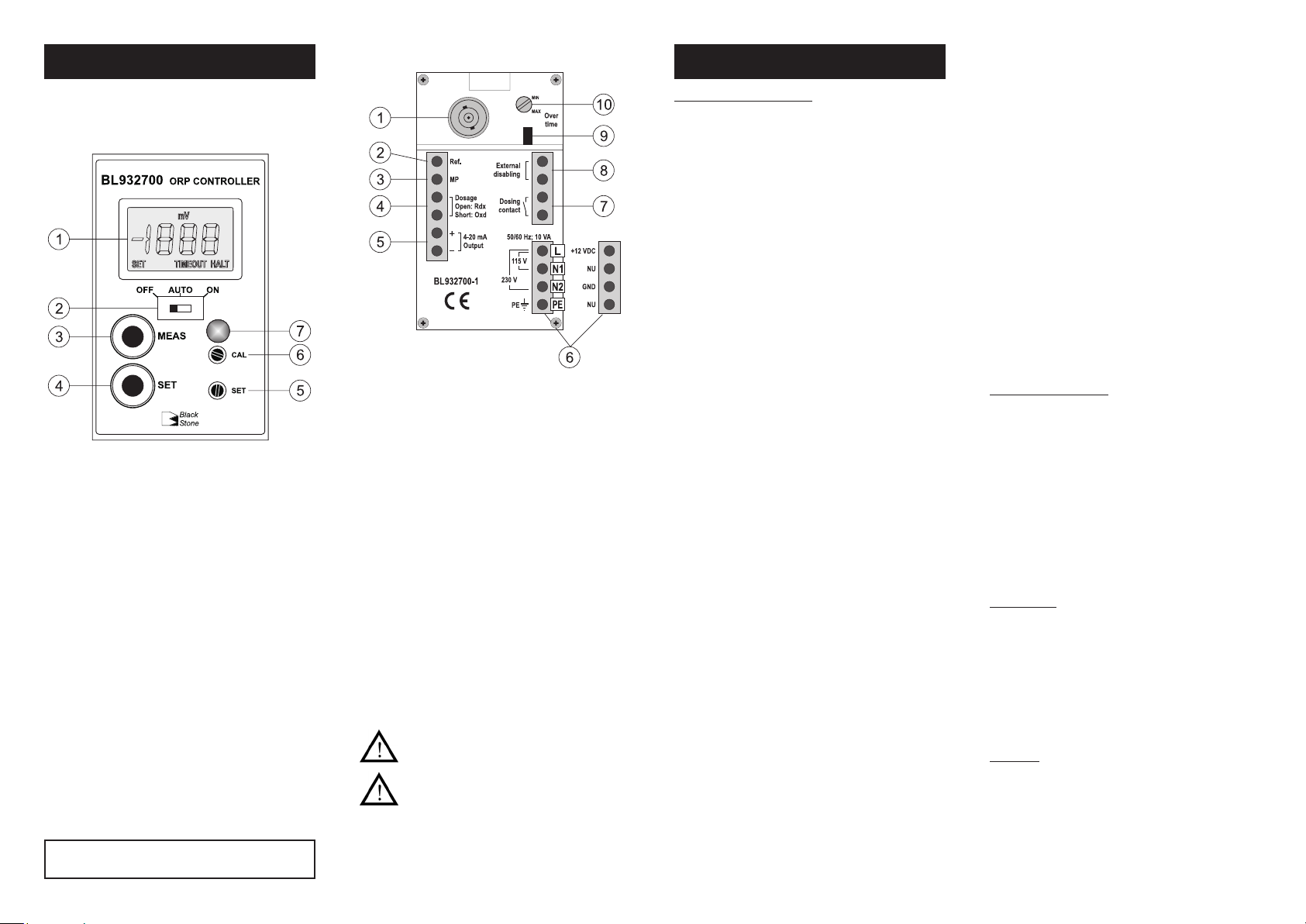
FUNCTIONAL DESCRIPTION
Front panel
1. Liquid Crystal Display
2. Switch for selecting dosing mode:
• OFF = dosing disabled
• Auto = automatic dosage, depending on setpoint value
and dosing selection
• ON = dosing always active
3. MEAS key to set the instrument to measurement mode
4. SET key to display and set the setpoint value
5. SET trimmer to adjust the setpoint value (within
±1000mV)
6. CAL trimmer
7. 3-colour LED indicator:
• Green = meter in measurement mode
• Orange/Yellow = dosing in progress
• Red, blinking = indicates an alarm condition
Hanna Instruments reserves the right to modify the design,
construction or appearance of its products without advance notice.
Rear panel
1. BNC plug for ORP electrode
2. Connection for electrode reference
3. Connection for potential Matching Pin
4. Rdx/Oxd dosage selection terminal:
• contact open = reductant selection
• contact closed = oxidant selection
5. 4-20 mA output terminal for recorder connection
6. Power supply terminal:
• for BL932700-0 model: 12 Vdc adapter
• for BL932700-1 model: 115 Vac or 230 Vac option
7. This contact acts as a switch for driving the dosing system
(e.g. dosing pump)
8. External control and disabling of dosing system
9. Jumper for enabling (jumper in) or disabling (jumper
removed) the overtime control
10. Trimmer for overtime setting (typically from 5 to 30
minutes)
All external cables connected to the rear panel
should end with cable lugs.
A circuit breaker (rated 6A max.) must be
connected in close proximity to the equipment,
and in a position easy to reach by the operator,
for disconnection of the instrument and of all
the devices connected to the relays.
OPERATIONS
REAR PANEL CONNECTIONS
Terminals #1, #2 and #3: Electrode
• Connect an ORP electrode to the meter’s BNC plug (#1).
• To benefit from the differential input, connect the proper
electrode wire (if available) or a cable with a potential
matching pin (grounding bar) to the relevant terminal (#3)
on the rear panel.
Note: When the Matching Pin can not be immersed together
with the electrode in the solution, disable the differential
input by shorting terminals #3 (Matching Pin) and #2
(Electrode Reference) with a jumper wire.
Terminals #4: Dosing selection
• For Rdx dosage, leave the circuit open.
• For Oxd dosage, short the terminals with a jumper wire.
Terminals #5: 4-20 mA Output
• These output terminals are used for connecting a recorder.
The output is from 4 to 20 mA and is proportional to the
measured ORP value.
Terminals #6: Power Supply
• Model BL932700-0: connect the 2 wires of a 12 Vdc power
adapter to the terminals +12 Vdc and GND.
• Model BL932700-1: connect a 3-wire power cable to
the terminals while paying attention to the correct earth
(PE), line (L) and neutral (N1 for 115 V or N2 for 230 V)
contacts.
Terminals #7: Dosing Contact
• This contact drives the dosing system according to the
selected setpoint and dosing direction:
• if “Rdx” dosage is set, the relay is ON and dosing
activated if measured value is higher than setpoint;
• if “Oxd” dosage is set, the relay is ON and dosing
activated if measured value is lower than setpoint.
Note: The setpoint has a typical hysteresis value comparable
to the meter’s accuracy.
Terminals #8: External Disabling Contact
• This is a normally open contact and can be used for example
for connecting a level controller.
• When the contact is closed, any dosing action stops, the
LED indicator on the front panel will blink Red and the LCD
will show the “HALT” warning message.
Note: If the OFF/Auto/ON switch is in ON position, the dos-
ing action will not stop, even if the external disabling
contact is closed. Dosage will proceed, the LED indicator
will light up Orange/Yellow and the LCD will show the
“HALT” warning message.
Overtime system: jumper (#9) and trimmer (#10)
• This system allows the user to set a maximum dosing period,
by adjusting the rear trimmer from 5 (min) to approx. 30
(max) minutes.
• When the set time is exceeded, any dosing action stops, the
LED indicator on the front panel will blink Red and the LCD
will show the “TIMEOUT” warning message. To exit the
overtime condition, set the OFF/Auto/ON switch to OFF
position, and then to Auto again.
• For disabling the overtime feature, simply remove the jumper
from the rear panel.
Note: The overtime system works only if the OFF/Auto/ON
switch is in Auto position.
OPERATING THE METER
Before proceeding make sure that:
• the setpoint value has been properly adjusted;
• all rear panel wiring and selections are correct;
• the OFF/Auto/ON switch is in the desired position.
Install or immerse the electrode in the solution to be monitored, then press the MEAS key (if necessary).
The LCD will show the ORP (mV) value. The LED indicator
will light up Green when the meter is in measurement mode
and dosing is not active, while it will light up Orange/Yellow
signaling that a dosing action is in progress.
CALIBRATION
This meter is factory calibrated. Anyway, it is possible to check
the calibration as follows:
• ensure the meter is in measurement mode;
• immerse electrode and Matching Pin (if used) in one of the
available ORP test solutions (see “Accessories”);
• shake briefly and wait for reading to stabilize;
• if necessary, adjust reading through the CAL trimmer.
SETPOINT
Press the SET key: the display will show the default or previously adjusted value, together with the ”SET“ indication. Using
a small screwdriver adjust the SET trimmer until the desired
setpoint value is displayed. After 1 minute the meter automatically returns to the normal mode; if not, press the MEAS key.
ISTBL2700 09/17
 Loading...