

Page 1
Instruction Manual
BL 7916 - BL 7917
pH and ORP
Controller &
Dosing Pump
http://www.hannainst.com
These Instruments are in
Compliance with the CE Directives
Page 2

Dear Customer,
Thank you for choosing a Hanna product.
Please read this instruction manual carefully before using the pump.
This manual will provide you with the necessary information for a
correct use of the pump, as well as a precise idea of its versatility. If
you need additional technical information, do not hesitate to e-mail
us at tech@hannainst.com.
These instruments are in compliance with the
EN 50081-1 and EN 50082-1.
TABLE OF CONTENTSTABLE OF CONTENTS
TABLE OF CONTENTS
TABLE OF CONTENTSTABLE OF CONTENTS
PRELIMINARY EXAMINATION........................................................ 3
GENERAL DESCRIPTION ................................................................4
FLOW RATE CHART.......................................................................5
FUNCTIONAL DESCRIPTION BL 7916 ............................................6
FUNCTIONAL DESCRIPTION BL 7917 ............................................7
SPECIFICATIONS...........................................................................8
VALVE / HOSE ASSEMBLY DIAGRAM .............................................9
MECHANICAL DIMENSIONS ........................................................10
INSTALLATION........................................................................... 11
OPERATIONAL GUIDE ................................................................. 18
pH CALIBRATION ....................................................................... 22
TROUBLESHOOTING GUIDE ........................................................23
MAINTENANCE ........................................................................... 24
ELECTRODE CONDITIONING AND MAINTENANCE...........................26
TAKING REDOX MEASUREMENTS.................................................30
CHEMICAL COMPATIBILITY GUIDE ................................................ 32
ACCESSORIES.............................................................................34
WARRANTY ................................................................................ 41
OTHER PRODUCTS FROM HANNA ............................................... 42
CE DECLARATION OF CONFORMITY .............................................. 43
directives
ISO 9000 Certified
Company since 1992
Page 3

PRELIMINARY EXAMINATIONPRELIMINARY EXAMINATION
PRELIMINARY EXAMINATION
PRELIMINARY EXAMINATIONPRELIMINARY EXAMINATION
Remove the pump from the packing material and examine it carefully
to make sure that no damage has occurred during shipping. If there
is any noticeable damage, notify your Dealer.
Each pump is supplied complete with:
• 7 m (23') LPDE suction and discharge tubing
• Power cord
• Instruction manual
Note: Save all packing material until you are sure that the pump
functions correctly. Any defective item must be returned in the
original packaging together with the supplied accessories.
READ THE INSTRUCTIONS ATTENTIVELY
BEFORE INSTALLING OR OPERATING YOUR PUMP
The BL electronic dosing pumps are easy to use. We recommend,
however, that you read the entire manual before using the pump.
Familiarity with the features and controls of the unit will give you a
better idea of the dosing potential and help reduce operator errors.
Please operate the pump only as directed in the instruction manual.
Follow all general safety guidelines during operation.
Remember: electrical devices are potentially hazardous. Check that the
voltage of the installation matches the voltage indicated on the
specification label on the back of the pump.
Note: It is the responsibility of the user to install and ground the
pump properly; it is highly recommended to install an external
switch.
Each pump is protected by a 250V fuse that is located together with
1 spare in a drawer on the power socket under the pump.
Always store chemicals in safe, out of reach places. Follow the
directions for use with each chemical. Do not assume chemicals are the
same because they look alike. Hanna Instruments cannot be held
responsible for the misuse of chemicals or the pump.
Always wear protective clothing (gloves and safety glasses) when
working near chemical dosing pumps. When pumping chemicals,
make sure all tubes are securely attached to the fittings. It is
recommended that tubing is shielded to prevent possible injury in
case of rupture or accidental damage.
Avoid using a pipe wrench or pliers on plastic parts and connectors.
These are best tightened with an open end or crescent wrench. Avoid
3
Page 4

overtightening these parts as this could cause damage to the seats
and threads.
If a hose is used, it should be securely fastened to columns, walls,
braces, etc. This will ensure that the hose connection will remain tight
and leak free. Shield the hose from direct sunlight. Sunlight can
cause an autocatalytic reaction with some chemicals and weaken the
hose walls.
The arrow on the pump head indicates the direction of chemical flow
and should always point upwards (vertically). Never position the
pump horizontally with suction and discharge valves horizontal.
Locate the pump in an area out of the reach of children and pets.
All pumps undergo stringent tests to ensure that they comply with
their stated specifications and are calibrated at the maximum rated
pressure.
Unplug the instrument from the power supply before
replacing the fuse or making any electrical connections.
GENERAL DESCRIPTIONGENERAL DESCRIPTION
GENERAL DESCRIPTION
GENERAL DESCRIPTIONGENERAL DESCRIPTION
The BL 7916 and BL 7917 Control/Pump System offer respectively a
pH and ORP monitoring system with proportional control of a
diaphragm pump and an LCD readout.
Features include:
• Two advanced instruments in one compact unit
• Proportional control for precisely maintained set-points
• Rugged construction with a one-piece casing and a transparent cover to protect controls and terminals
• Chemically resistant non-clogging pump head and superior
materials for all components in contact with the chemicals
being dosed (see page 32 for details)
• Convenient installation with all controls on front panel
• A solenoid-driven pump
• Automatic overheat protection and a built-in LCD display
• Alarm output: the alarm of the BL 7916 will be activated if
the measured pH value is 2 pH units higher or lower than the
setpoint. BL7917's alarm will activate if the mV value is
200mV higher or lower than the setpoint.
• Auxiliary dosing contacts. This will drive other equipment such
as mixers, priming pumps, etc.
4
Page 5
FLOW RATE CHARTFLOW RATE CHART
FLOW RATE CHART
FLOW RATE CHARTFLOW RATE CHART
The following chart shows the inverse relationship between flow rate
and pressure.
The table below shows typical reduction of the flow rate with an
increase of pressure. The pump supplied with the system has a
capacity of 13.3 LPH (3.5 GPH) at 0.5 BAR (7.4 PSI).
BL 7916 / BL 7917
FLOW / PRESSURE
BAR (PSI) LPH (GPH)
0.5 (7.4)
1.0 (14.7)
2.0 (29.4)
3.0 (44.1)
4.0 (58.8)
13.3 (3.46)
11.7 (3.04)
10.1 (2.63)
9.0 (2.33)
7.8 (2.03)
5
Page 6
FUNCTIONAL DESCRIPTION BL 7916FUNCTIONAL DESCRIPTION BL 7916
FUNCTIONAL DESCRIPTION BL 7916
FUNCTIONAL DESCRIPTION BL 7916FUNCTIONAL DESCRIPTION BL 7916
1. Discharge Valve Assembly
2. Pump head
3. Suction Valve Assembly
4. Hose
5. Liquid Crystal Display
6. Offset Calibration Trimmer
7. Setpoint Adjustment Trimmers (FINE and COARSE)
8. Slope Calibration Trimmer
9. Acid/Base Selection Switch
10. Display Mode Selection Switch (SET or MEASURE)
11. Terminal Connections
12. BNC Connector for pH electrode
13. Overheating LED
14. Power Socket and Fuse Holder
15. Cable Glands
Unplug the instrument from the power supply before
replacing the fuse or making any electrical connections.
6
Page 7

FUNCTIONAL DESCRIPTION BL 7917FUNCTIONAL DESCRIPTION BL 7917
FUNCTIONAL DESCRIPTION BL 7917
FUNCTIONAL DESCRIPTION BL 7917FUNCTIONAL DESCRIPTION BL 7917
1. Discharge Valve Assembly
2. Pump head
3. Suction Valve Assembly
4. Hose
5. Liquid Crystal Display
6. Setpoint Adjustment Trimmers (FINE and COARSE)
7. Reduction/Oxidation Selection Switch
8. Operating Mode Selection Switch (SET or MEASURE)
9. Terminal Connections
10. BNC Connector for ORP electrode
11. Overheating LED
12. Power Socket and Fuse Holder
13. Cable Glands
Unplug the instrument from the power supply before
replacing the fuse or making any electrical connections.
7
Page 8
SPECIFICATIONSSPECIFICATIONS
SPECIFICATIONS
SPECIFICATIONSSPECIFICATIONS
BL7916D BL7916U
Range 0.00 to 14.00 pH
Resolution 0.01 pH
Accuracy (@20°C/68°F) ±0.01 pH
Typical EMC Deviation ±0.1 pH
Input High Impedance 10¹² Ohm
Dosage Proportional: acid or basic. User selectable
Dosing Contact Isolated, 2A, Max. 240V, resistive load, 1,000,000 strokes
Alarm Contact Isolated, 2A, Max. 240V, resistive load, 1,000,000 strokes
Calibration Offset: ±1 pH by offset trimmer
Slope: 85 to 115% by slope trimmer
Recorder Output 4 to 20 mA
Power Supply 230V ±15% 115V ±15%
50/60Hz (40W) 50/60Hz (40W)
Environment 0 to 50°C (32 to 122°F);
max 85% RH non-condensing
Dimensions W x D x H: 221 x 142 x 181 mm (8.7 x 5.6 x 7.1)
Weight Approximately 5 Kg (11 lb.)
BL7917D BL7917U
Range -999 to +999 mV
Resolution 1 mV
Accuracy (@20°C/68°F) ±5 mV
Typical EMC Deviation ±6 mV
Input High Impedance 10¹² Ohm
Dosage Proportional: oxidizing or reducing. User selectable
Dosing Contact Isolated, 2A, Max. 240V, resistive load, 1,000,000 strokes
Alarm Contact Isolated, 2A, Max. 240V, resistive load, 1,000,000 strokes
Recorder Output 4 to 20 mA
Power Supply 230V ±15% 115V ±15%
50/60Hz (40W) 50/60Hz (40W)
Environment 0 to 50°C (32 to 122°F);
max 85% RH non-condensing
Dimensions W x D x H: 221 x 142 x 181 mm (8.7 x 5.6 x 7.1)
Weight Approximately 5 Kg (11 lb.)
8
Page 9
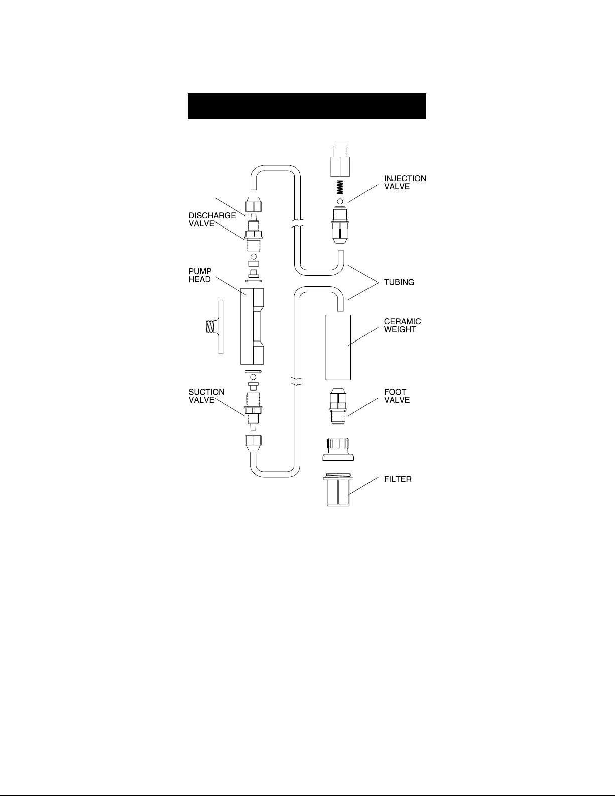
VALVE / HOSE ASSEMBLY DIAGRAMVALVE / HOSE ASSEMBLY DIAGRAM
VALVE / HOSE ASSEMBLY DIAGRAM
VALVE / HOSE ASSEMBLY DIAGRAMVALVE / HOSE ASSEMBLY DIAGRAM
NECK
9
Page 10
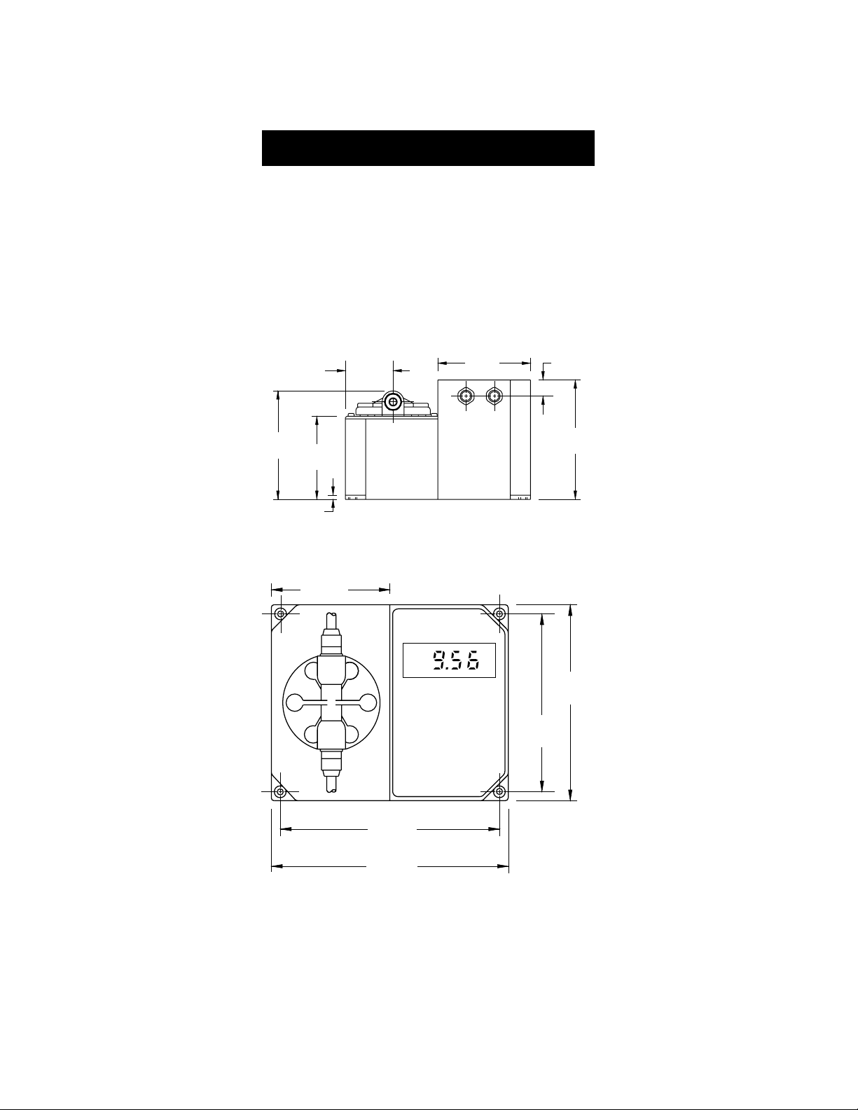
MECHANICAL DIMENSIONSMECHANICAL DIMENSIONS
MECHANICAL DIMENSIONS
MECHANICAL DIMENSIONSMECHANICAL DIMENSIONS
The Controller/Pump series of instruments are enclosed in a modular
housing for maximum protection. The dimensioned illustrations show
the layout of the Controller/Pumps and how they utilize the one-piece
polypropylene, injection-molded housing. Since there are no joints or
screws holding different sections of the housing together, the case is
extremely rugged and sturdy.
BOTTOM VIEW
55mm
2.16"
110mm
4.33"
17mm
.67"
129mm
5.08"
99mm
3.90"
5mm
0.19"
110mm
4.33"
142mm
5.60"
FRONT VIEW
pH
181mm
7.13"
164mm
6.45"
204mm
8.03"
221mm
8.70"
10
Page 11
INSTALLATIONINSTALLATION
INSTALLATION
INSTALLATIONINSTALLATION
Materials Needed
• LDPE hose (7 meter/22 feet) (included) or other type of tubing
(Teflon® for example) more suitable for a specific application
(optional)
• Power cord (included)
Optional Accessories
• 4 each, ceramic weights (HI721008)
• 1 each, foot valve assembly (HI721005)
• 1 each, injection valve assembly (HI721004)
Location
A suitable location should:
• be near to a power source
• be conveniently close to the injection point
• allow easy access to the flow rate control and pipe or hose
connections
• be no more than 1.5 meters (5 feet) above the operating
position of the suction valve assembly.
Dimensions for Installation
BlackStone Pumps are designed for permanent installation.
The pump can be mounted directly on a wall or tank (see page 10 for
the specific mounting dimensions).
Power Requirements
BlackStone pumps are designed to operate to specifications within the
following voltage ranges:
100 - 130 Volts for 115V models
200 - 250 Volts for 230V models
Teflon® is a registered Trademark of "du Pont de Nemours & Co."
11
Page 12

To ensure maximum performance, check the voltage at the point of
supply to verify that it is sufficient. It is recommended that you install a
1 Amp circuit breaker between the pump and the power supply. This
will give additional protection to the internal circuit and provide a
convenient way to disconnect the power supply prior to servicing the
pump, if needed.
Injection Point
• Choose an injection point that allows you to mount the injection
valve assembly vertically.
• The spring in the injection valve assembly (HI721004) adds
approximately 1.5 bar of back pressure. If pumping into a
high back pressure, the spring should be removed.
Other Considerations
• If you are mounting the system to a wall, column, etc., be sure
it is strong enough to support the weight of the entire system.
• The ambient temperature of the pump, when in operation,
should be between 0 and 50°C (32 to 122°F) and should be
protected from direct exposure to outdoor elements (direct sunlight, rain, extreme temperatures, high humidity, etc.).
• Generally speaking, the shorter the suction distance, the more
efficient the pump operates.
• The pump should be placed in a conventional location that will
allow easy access to the control and connections. It should be
placed so that regular visual inspections of the connections and
hoses are facilitated.
Vertical Surface Mounting
Once you have selected the best installation site, simply screw or bolt
the unit into a wall or mounting panel above the chemical feed tank.
The 4 mounting screw holes on the pump will accommodate up to a 5
mm (3/16") screw or bolt (remember to use heavy screws or bolts to
secure the system). Be sure you do not over tighten and cause excessive
stress on the mounting holes.
Make sure to leave a slight overhang in front to allow for the
connection cable.
Power Supply
Connect the power cord to the female socket of the pump and by doing
so also grounding it. The power socket contains a 250V fuse. Since
there is no on/off switch, it is suggested to install an outside switch.
12
Page 13
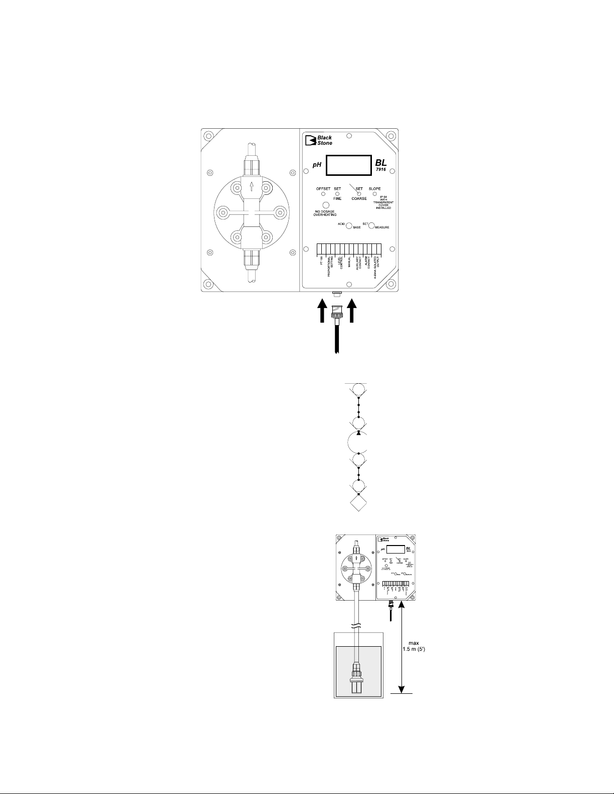
Probe connections
Connect the pH/ORP electrode to the BNC socket of the pump.
Permanent Connection using 3/8" PVC pipe
All piping for the pump feed and discharge should be plumbed to the location
of the pump.
The threads on both valve assemblies
allow the use of standard 3/8" (European) pipe fittings for permanent pipe
connections.
Diagram for Rigid Pipe Hose
UNION CONNECTION
ADAPTER
DISCHARGE VALVE
PUMP
SUCTION VALVE
ADAPTER
FOOT VALVE
-
FILTER
The foot valve assembly (HI721005)
should always hang vertically and not
lay horizontal on the bottom of the tank
or drum.
A vertical assembly will ensure that the
valve is positioned properly and prevent
loss of prime.
For the U.S. standard installations, use
PVC adapters to connect the suction and
discharge valves to the PVC pipe.
13
Page 14
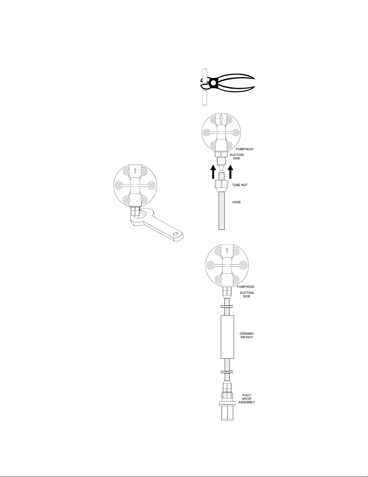
Hose Connections
• Cut a long enough section of the
hose to reach the suction valve of
the pump head from the feed tank.
Allow some slack in the hose and be
sure it is not kinked or twisted.
• Slip a hose connector onto the hose
over the head valve and up to the
bottom of the threads ensuring it is
fully seated.
• Slide the connector up to the threads
and tighten to form a seal.
• Slip the ceramic weight (HI721008)
and a connector over the other end of
the hose.
• Attach the foot valve assembly
(HI721005) to the hose and slide the
connector up to the threads and tighten
to form a seal.
14
Page 15

• Repeat the same installation procedure for the hose connections
on the discharge end with the injection assembly (HI721004).
• Secure the hose so that its movement is minimized when the
pump is operating. Excessive hose movement could cause the
connectors to loosen and result in leakage.
Assembling the Hose to the Valve
The end of the valve is specially tapered to
form a leak free seal when the hose is
properly installed.
Be sure to seat the hose completely so that
there is no gap. Push the hose until it covers
the end of the valve completely.
Suction and Discharge Valves
The suction and discharge valves located
on the pump head should not be interchanged as they are different internally.
The discharge valve is fitted with a valve
guide and will not function properly if
used on the suction side.
15
Page 16

LEGEND
HOSE PIPE
CONNECTION
RESEVOIR
MANUAL
SHUTOFF
VALVE
PUMP
FILTER /
FOOT VALVE
CHECK VALVE
EXAMPLE OF TYPICAL INSTALLATIONS
Flooded Suction Installation
Suggested Installation for consistent output when using a low
stroke rate. Also suggested for
highly viscous chemicals.
A slight suction pressure avoids
self-priming problems, especially
with high viscosity liquids.
Suction Lift Installation
Suggested installation for most in-line applications with nominal output and
pressures.
The maximum self-priming height is
1.5 m (5 ft.). It is advisable to install a
level controller in order to stop the pump
when feed tank (reservoir) liquid level is
low.
Uphill Installation
Suggested installation whenever the supply is located higher than the
discharge point; typically a waste water application.
It is important to install the Injection valve to prevent siphoning.
16
Page 17

Downhill Installation
Suggested installation when pumping from one container to another,
each at different levels and with only nominal pressure.
START-UP
At start-up, purge all chemical gases and air from the suction tubing,
valves and pump head. Start the pump.
When all the air or gas is vented, the solution being metered will
appear in the output line.
Note: only when operating under pressure, the pump must be started
unloaded.
17
Page 18

OPERATIONAL GUIDEOPERATIONAL GUIDE
OPERATIONAL GUIDE
OPERATIONAL GUIDEOPERATIONAL GUIDE
• Unscrew and remove the transparent front panel cover and
gasket seal for access to the terminals.
• Remove the protective plastic plate covering the terminals by
removing the 2 screws on both sides of the plate.
TERMINAL CONNECTIONS BL 7916
18
Page 19

TERMINAL CONNECTIONS BL 7917
Pt100 (for BL 7916 only)
A 2-wire Pt100 can be connected to provide automatic temperature
compensation of the pH measurements. The pump is supplied with a
100 ohm resistor connected to the 2 Pt100 terminals. This delivers a
fixed temperature compensation of 25°C (77°F). The Pt100 is recommended only in special instances where very high accuracy is
absolutely necessary since the error is only 0.03 pH for a temperature
difference of 10°C in the pH 6 to 8 range. The error will consequently
be less than 0.09 pH at readings from pH 4 to 10 when the
temperature is in the 15°C (59°F) to 35°C (95°F) range.
PROPORTIONAL SETTING
The pump is supplied with a 10K resistor connected to these
terminals. With this value the pump works at 100% of the rating
when the difference between measure and setpoint is more than
150 mV (BL 7917) or 1.5 pH (BL 7916). It goes into proportional
dosing for values less than the above.
You can vary this hysteresis band by simply changing the resistor as
follows:
BL 7916 BL 7917
0.50 pH 4.7K 50 mV 4.7K
1.00 pH 5.6K 100 mV 5.6K
1.50 pH 10.0K 150 mV 10.0K
2.00 pH 18.0K 200 mV 18.0K
LEVEL CONTROL
The pump is supplied with these two terminals short-circuited. A
contact coming from a level controller (e.g. HI 7871, HI 7873) can be
connected to these terminals. If this contact is closed, the pump works
normally. If it opens, the unit will not pump even if the controller
commands it.
19
Page 20

For example, a level controller can be placed in the tank of the liquid
being dosed so that the pump is stopped when the chemicals are
exhausted.
MANUAL
An auxiliary switch can be connected to these terminals to force the
unit to pump whatever value is measured by the controller. This
might be needed for example when the pump needs to be primed.
AUXILIARY CONTACT
The controller can drive a relay when the measure overtakes the
setpoint. The contact available on the terminals can be normally open
or closed. It can be used as a switch to drive an external mixer when
the pump is dosing, or can activate an auxiliary pump or any other
device. With BL 7916, the contact can be selected to remain open
when the pH value is within the set limits (the pump is not dosing)
and closed when the pump is dosing or viceversa.
By shorting the Common (middle) terminal with the NO or NC
terminal on the driving circuit inside the controller section, a normally
open or a normally closed state can be achieved, as shown below:
ALARM CONTACT
If the reading drifts from the setpoint by more than ±2.00 pH in
BL 7916 and ±200 mV in BL7917, an external alarm can be
activated. The contact is rated at 2 amps at 220VAC. No power is
supplied through the system and it is an open/closed contact only.
With BL 7916, the contact can be selected to be closed when the
alarm is activated and open when the alarm is off or viceversa. Short
the middle terminal located on the driving circuit inside the controller
section with the NO or NC terminal (see above).
4-20 mA ISOLATED OUTPUT
A 4-20 mA proportional output is available in these connections:
4 mA=0 pH; 20mA=14 pH (BL 7916)
and
4 mA=-999 mV; 20mA=+999 mV (BL 7917).
The output is optically isolated.
20
Page 21

SETPOINT ADJUSTMENTS
• Move the display selector switch to SET.
• With a small screwdriver adjust the SET COARSE trimmer to
display a value close to the desired setpoint e.g. 7.00.
• Adjust the SET FINE trimmer to display the exact setpoint value.
• Once the desired setpoint is achieved, move the display selector
switch back to MEASURE.
ACID OR BASE SELECTION (BL 7916 only)
If an acid chemical is to be dosed, move the
ACID/BASE switch to ACID. This means that
the pump will dose when pH measurements
are higher than the setpoint.
If an alkaline chemical is to be dosed, move
the ACID/BASE switch to BASE. This means
that the pump will dose when pH measurements are lower than the setpoint.
REDUCING OR OXIDIZING SELECTION (BL 7917 only)
If a reducing chemical is to be dosed, move
the RED./OXID. switch to RED. This means
that the pump will dose when redox measurements are higher than the setpoint.
If an oxidizing chemical is to be dosed, move
the RED./OXID. switch to OXID. This means
that the pump will dose when the redox
measurements are lower than the setpoint.
The wires and cables needed for all connections can be fed through
the two cable fittings located below the terminals. It is important to
attach these cables properly because pump vibrations could loosen
them. Replace the transparent cover and fasten the screws.
21
Page 22

pp
H CALIBRATIONH CALIBRATION
p
H CALIBRATION
pp
H CALIBRATIONH CALIBRATION
BL 7916 only:
• Ensure that the display selector switch is set to MEASURE and dip
the electrode tip in a neutral buffer solution (pH 7.01).
• Adjust the OFFSET trimmer to display 7.01 on the LCD.
• Rinse the electrode with clean water and
dip the electrode tip in pH 4.01 (acidic)
or pH 10.01 (alkaline) buffer solution.
• Adjust the slope trimmer to read 4.01 or 10.01 on the LCD.
The slope calibration with pH 4.01 buffer is suggested if the controller
will be used for acid measurements or pH values below 7, pH 10.01
is in turn recommended for alkaline measurements or pH values
above 7.
22
Page 23

TROUBLESHOOTING GUIDETROUBLESHOOTING GUIDE
TROUBLESHOOTING GUIDE
TROUBLESHOOTING GUIDETROUBLESHOOTING GUIDE
ELECTRICAL
The pump does not operate when turned ON:
• Check the power supply and connections. Voltage should be
between 100 - 130 VAC for 115 V models and between 200
- 250VAC for 230 V models.
• See Installation section on page 11 or call your dealer or the
nearest Hanna Customer Service Center for technical assistance.
OPERATING
Display does not indicate:
• Check that the pump is properly plugged in
• Check the fuse.
Display shows 1 on the far left hand side:
• Check electrode and/or electrode cable.
"No Dosage" LED is lit:
• Check the tank where the level controller is working or verify
the connection on the terminals (they must be short for the
pump to dose).
LIQUID
The pump operates but does not prime:
• Check for a clogged or loose filter on the suction valve
assembly. Retighten if necessary.
• Check to see if the pump is too high above the foot valve
assembly (HI721005) in the feed tank. This vertical distance
should not exceed 1.5 meters (5 feet). Either lower the pump
or raise the feed tank.
• Check the pump head, suction and discharge valves for
blockage.
Pump flow rate is reduced:
• Check the pump head, discharge and injection valve assembly
for any clogging. Clean and reassemble.
• Check for any additional back pressure created since the last
flow rate was conducted.
• Check for any changes in the viscosity of the chemical being
used.
• Be sure that valves have been properly installed in the pump
head.
23
Page 24

Leakage at the connections:
• Be sure that the hose is fully seated and hose connectors are
tight.
• Be sure that valves are tight and O-rings are in place.
Leakage around the pump head:
• Be sure that the valves are tight and O-rings are in place and
the head screws (hex bolts) are tight.
MAINTENANCEMAINTENANCE
MAINTENANCE
MAINTENANCEMAINTENANCE
Your BlackStone Pump is designed to give you years of trouble-free
service. Maintenance should be the preventative type, that is, periodic
cleaning and inspecting for any damage or leakage.
CLEANING THE SUCTION, DISCHARGE AND INJECTION
VALVES
Remove the valves from the pump head, the injection fitting and the
feed.
Keep the suction and discharge valves separated as they are not
interchangeable.
Disassemble each valve and clean it with a neutral liquid. Inspect the
Kynar® springs.
After cleaning the glass balls, inspect them for any excessive wear due
to abrasion from the chemical. Replace if necessary with parts from
HI721102, HI721103, HI721004 and HI721005 (see page 34
for listing).
When reinstalling the valves into the pump head, tighten by hand
first and then with a wrench ¼ to ½ turn.
INSPECTING THE HOSE (if used as supplied with the pump)
Inspect to see if the hose has worn out or weakened due to the
chemicals. Pay particular attention for any signs of abrasion or discoloration. Also check the connectors to ensure they are tight.
Replace if necessary with parts from HI720032.
CLEANING THE PUMP HEAD
The pump head should be cleaned at regular intervals and at
least once a year. Remove the deposits that form in the cavities with
a solution that is neutral to the chemical the pump has been dosing.
Inspect the head for any cracks or worn areas.
Replace if necessary with parts from HI721106 (pump head).
Kynar® is registered Trademark of "Pennwalt Co."
24
Page 25

SCHEDULED MAINTENANCE
After 50 hours
Tight the pump head screws with a torque force of 2.5 Nm (22"
lbf).
After 12 months
It is recommended to replace HI721102, HI721103 (suction and
discharge valves assemblies) as well as the O-rings. The LDPE hose can
also deteriorate over time and, for safety reasons, should also be
changed with HI720032.
After 24 months
It is recommended to replace HI721102, HI721103, HI720032
and HI721106.
25
Page 26

ELECTRODE CONDITIONINGELECTRODE CONDITIONING
ELECTRODE CONDITIONING
ELECTRODE CONDITIONINGELECTRODE CONDITIONING
AND MAINTENANCEAND MAINTENANCE
AND MAINTENANCE
AND MAINTENANCEAND MAINTENANCE
* Only available with refillable electrodes. For industrial applications, gel-filled
electrodes are preferable due to lesser maintenance requirements.
PREPARATION
Remove the protective cap.
DO NOT BE ALARMED IF ANY SALT DEPOSITS ARE PRESENT.
This is normal with electrodes and they will disappear when rinsed
with water.
During transport tiny bubbles of air may have formed inside the glass
bulb. The electrode cannot function properly under these conditions.
26
Page 27

These bubbles can be removed by "shaking down" the electrode as
you would do with a glass thermometer.
If the bulb and/or junction are dry, soak the electrode in HI 70300
Storage Solution for at least one hour.
For refillable electrodes**:
If the refill solution (electrolyte) is more than 2½ cm (1") below the fill
hole, add HI7082 3.5M KCl Electrolyte Solution for double junction or
HI7071 3.5M KCl+AgCl Electrolyte Solution for single junction electrodes.
For AmpHel® electrodes:
If the electrode does not respond to pH changes, the battery is run
down and the electrode should be replaced.
TEST MEASUREMENT
Rinse the electrode tip with distilled water.
Immerse the tip (bottom 4 cm / 1½") in the sample and stir gently
for approx. 30 seconds.
For a faster response and to avoid cross contamination of the samples,
rinse the electrode tip with the solution to be tested, before taking
your measurements.
STORAGE
To minimize clogging and assure a quick response time, the glass
bulb and the junction should be kept moist and not allowed to dry
out. This can be achieved by installing the electrode in such a way
that it is constantly in a well filled with the sample (stream or tank).
When not in use, replace the solution in the protective cap with a few
drops of HI70300 Storage Solution or, in its absence, HI7007
pH 7.01 Buffer Solution.
Follow the Preparation Procedure above before taking measurements.
Note: NEVER STORE THE ELECTRODE IN DISTILLED OR DEIONIZED
WATER.
PERIODIC MAINTENANCE
Inspect the electrode and the cable. The cable used for the connection
to the controller must be intact and there must be no points of broken
insulation on the cable or cracks on the electrode stem or bulb.
Connectors must be perfectly clean and dry. If any scratches or cracks
are present, replace the electrode. Rinse off any salt deposits with
water.
**For industrial applications, gel-filled electrodes are preferable due to lesser maintenance requirements.
AmpHel® is a registered Trademark of "Hanna Instruments"
27
Page 28

For refillable electrodes**:
Refill the electrode with fresh electrolyte (HI7071 for single junction or
HI7082 for double junction electrodes). Allow the electrode to stand
upright for 1 hour. Follow the Storage Procedure above.
CLEANING PROCEDURE
General Soak in Hanna HI7061 General Cleaning Solu-
tion for approximately ½ hour.
Removal of films, dirt or deposits on the membrane/junction:
Protein Soak in Hanna HI7073 Protein Cleaning Solu-
tion for 15 minutes.
Inorganic Soak in Hanna HI7074 Inorganic Cleaning Solu-
tion for 15 minutes.
Oil/grease Rinse with Hanna HI7077 Oil and Fat Cleaning
Solution.
IMPORTANT: After performing any of the cleaning procedures rinse
the electrode thoroughly with distilled water, drain and refill the
reference chamber with fresh electrolyte, (not necessary for gel-filled
electrodes) and soak the electrode in HI70300 Storage Solution for at
least 1 hour before reinstalling it.
TROUBLESHOOTING
Evaluate your electrode performance based on the following.
• Noise (Readings fluctuate up and down) could be due to:
- Clogged/Dirty Junction: Refer to the Cleaning Procedure
above.
- Loss of shielding due to low electrolyte level (in refillable
electrodes only): refill with HI7071 for single junction or
HI7082 for double junction electrodes.
• Dry Membrane/Junction: Soak in Storage Solution HI70300
for at least 1 hour. Check to make sure the installation is such as
to create a well for the electrode bulb to constantly remain moist.
• Drifting: Soak the electrode tip in warm Hanna Solution
HI7082 for one hour and rinse tip with distilled water (refill with
fresh HI7071 for single junction electrodes and HI7082 for double
junction electrodes if necessary).
• Low Slope: Refer to the cleaning procedure above.
• No Slope: - Check the electrode for cracks in glass stem or
bulb (replace the electrode if cracks are found).
- Make sure cable and connections are not damaged nor lying in a pool of water or solution.
**For industrial applications, gel-filled electrodes are preferable due to lesser maintenance requirements.
28
Page 29

• Slow Response/Excessive Drift: Soak the tip in Hanna Solution HI7061 for 30 minutes, rinse thoroughly in distilled water
and then follow the Cleaning Procedure above.
• For ORP Electrodes: polish the metal tip with a lightly
abrasive paper (paying attention not to scratch the surface) and
wash thoroughly with water.
Note: with industrial applications, it is always recommended to keep
at least one spare electrode handy. When anomalies are not
resolved with a simple maintenance, change the electrode
(and recalibrate the controller) to see if the problem is
alleviated.
29
Page 30

TAKING REDOX MEASUREMENTSTAKING REDOX MEASUREMENTS
TAKING REDOX MEASUREMENTS
TAKING REDOX MEASUREMENTSTAKING REDOX MEASUREMENTS
Redox measurements allow the quantification of the oxidizing or
reducing power of a solution, and are commonly expressed in mV.
Oxidation may be defined as the process during which a molecule (or
an ion) loses electrons and reduction as the process by which electrons
are gained.
Oxidation is always coupled together with reduction so that as one
element gets oxidized, the other is automatically reduced, therefore
the term oxidation-reduction is frequently used.
Redox potentials are measured by an electrode capable of absorbing
or releasing electrons without causing a chemical reaction with the
elements with which it comes into contact.
The electrodes most usually available for this purpose have gold or
platinum surfaces; gold possesses a higher resistance than platinum
in conditions of strong oxidation such as cyanide, while platinum is
preferred for the measurements of oxidizing solutions containing
halides and for general use.
When a platinum electrode is immersed in an oxidizing solution a
monomolecular layer of oxygen is developed on its surface. This layer
does not prevent the electrode from functioning, but it increases the
response time. The opposite effect is obtained when the platinum
surface absorbs hydrogen in the presence of reducing mediums. This
phenomenon is rough on the electrode.
To make correct redox measurements the following conditions must
prevail:
– The surface of the electrode must be cleaned and smooth.
– The surface of the electrode must undergo a pretreatment in
order to respond quickly.
Because the Pt/PtO system depends on the pH, the pretreatment of
the electrode may be determined by the pH and the redox potential
values of the solution to be measured.
As a general rule, if the ORP mV reading corresponding to the pH
value of the solution is higher than the values in the table below, an
oxidizing pretreatment is necessary; otherwise a reducing pretreatment is necessary:
pH mV pH mV pH mV pH mV pH mV
0 990 1 920 2 860 3 800 4 740
5 680 6 640 7 580 8 520 9 460
10 400 11 340 12 280 13 220 14 160
30
Page 31

Reducing pretreatment: immerse the electrode for a few minutes in
HI 7091.
Oxidizing pretreatment: immerse the electrode for a few minutes in
HI 7092.
If the pretreatment is not performed, the electrode will take significantly longer to respond.
As with pH electrodes, gel-filled redox electrodes are more suitable for
industrial applications due to lesser maintenance requirements. However, if working with refillable electrodes, the electrolyte level should
not fall more than 2½ cm (1") below the fill hole and topped up if
necessary. Use HI 7071 Refill Solution for single junction and HI 7082
for double junction electrodes.
In the event that measurements are performed with solutions containing sulfides or proteins, the cleaning of the diaphragm of the
reference electrode must be performed more often.
In order to have a correct functioning of the ORP electrode, immerse
it into HI 7020 and measure the response; the obtained value should
be within 200 and 275 mV.
After this functional test, it is suggested to wash the electrode
thoroughly with water and proceed to the oxidizing or reducing
pretreatment before taking measurements.
When not in use, the electrode tip should be kept moist and far from
any type of mechanical stress which might cause damage. This can be
achieved by installing the electrode in such a way that it is constantly
in a well filled with the sample (stream or tank). The protective cap
can also be filled with HI70300 Storage Solution if the electrode is
not being used at all.
Note: with industrial applications, it is always recommended to keep
at least one spare electrode handy. When anomalies are not
resolved with a simple maintenance, change the electrode to
see if the problem is alleviated.
31
Page 32

CHEMICAL COMPATIBILITY GUIDECHEMICAL COMPATIBILITY GUIDE
CHEMICAL COMPATIBILITY GUIDE
CHEMICAL COMPATIBILITY GUIDECHEMICAL COMPATIBILITY GUIDE
PARTIAL LISTING OF CHEMICALS THAT CAN BE USED
WITH BLACKSTONE PUMPS
(Rated for 45°C. For higher temperatures consult your dealer or
nearest Hanna Customer Service Center)
Adipic Acid
Alcohol Amyl
Alcohol, Diacetone
Alcohol, Isoproyl
Alcohol, Methyl
Aluminium, Ammonium Sulfate
Aluminium Chloride
Aluminium Sulfate
Alums
Ammonium Carbonate
Ammonium Chloride
Ammonium Fluoride
Ammonium Hydroxide
Ammonium Nitrate
Ammonium Phosphate
Ammonium Sulfate
Aqua Ammonia
Arsenic Acid
Barium Carbonate
Barium Chloride
Barium Hydroxide
Barium Sulfate
Beer
Beet Sugar Liquors
Bismuth Carbonate
Back Liquor
Bleach
Borax
Boric Acid
Bromic Acid
Butyric Acid
Calcium Bisulfite
Calcium Carbonate
Calcium Chlorate
Calcium Chloride
Calcium Hydroxide
Calcium
Hypochlorite
Calcium Nitrate
Calcium Sulfate
Carbonic Acid
Castor Oil
Caustic Soda
Chloral Hydrate
Chromic Acid 50%
Citric Acid
Copper Chloride
Copper Cyanide
Copper Nitrate
Copper Sulfate
Corn Oil
Cottonseed Oil
Cresylic Acid
Crude Oil
Dextrose
Detergents (general)
Diesel Fuel
Dictyl Phthalate
Disodium Phosphate
Ethanol (1-95%)
Ethylene Dichloride
Ethylene Glycol
Fatty Acids
Ferric Chloride
Ferric Nitrate
Ferric Sulfate
Ferrous Chloride
Ferrous Sulfate
Fluoboric Acid
Fluosilicic Acid
Formaldehyde
Fruit Juice Pulp
Fuel Oil
Gallic Acid
Gasoline, Refined
Glucose
Glycerine or Glycerol
Glycolic Acid 30%
Hexane
Hydrazine
Hydrobromic Acid 20%
Hydrochloric Acid (Concentrated)
Hydrochloric Acid (Diluted)
Hydrofluoric Acid 60%
32
Page 33

Hydrogen Sulfide Aqueous
Solution
Hypochlorous Acid
Kerosene
Lactic Acid
Lard Oil
Lauric Acid
Lead Acetate
Linoleic Acid
Linseed Oil
Lithium Salts
Magnesium Carbonate
Magnesium Chloride
Magnesium Hydroxide
Magnesium Nitrate
Magnesium Oxide
Magnesium Sulfate
Maleic Acid
Malic Acid
Mercuric Chloride
Methanol
Methyl Sulfate
Milk
Mineral Oils
Noptha Petroleum
Nickel Chloride
Nickel Sulfate
Nitric Acid 50%
Oils and Fats
Oleic Acid
Olive Oil
Oxalic Acid
Palmitric Acid
Perchloric Acid 70%
Perchloroethylene
Petroleum Oils (sour)
Phenol
Phosphoric Acid
Photographic Solutions
Plating Solutions
Potassium Carbonate
Potassium Bromide
Potassium Chlorate
Potassium Chloride
Potassium Cyanide
Potassium Ferrocyanide
Potassium Hydroxide
Potassium Nitrate
Potassium Permanganate 10%
Potassium Phosphate
Potassium Sulfate
Propyl Alcohol
Propylene Dichloride
Sea Water
Silver Nitrate
Silver Plating Solutions
Soaps
Sodium Acetate
Sodium Bicarbonate
Sodium Bisulfate
Sodium Bisulfite
Sodium Borate
Sodium Chlorate
Sodium Chloride
Sodium Cyanide
Sodium Fluoride
Sodium Hexametaphosphate
Sodium Hydroxide 50%
Sodium Hypochlorite 18%
Sodium Metaphosphate
Sodium Nitrate
Sodium Peroxide
Sodium Phosphate
Sodium Silicate
Sodium Sulfate
Sodium Sulfide
Sodium Sulfite
Sodium Thiosulfate
Sour Crude Oil
Stannic Chloride
Stannous Chloride
Stearic Acid
Sulfur
Sulfuric Acid Concentration
Sulfurous Acid
Tannic Acid
Tanning Liquors
Tartaric Acid
Tetrachlorethane
Tetraethyl Lead
Tetralin
Tin Salts
Vegetable Oils
Vinegar
Water Acid, Mine
Water, Fresh
Water, Distilled
Water, Salt
Whiskey
Wines
Zinc Chloride
Zinc Sulfate
33
Page 34

ACCESSORIESACCESSORIES
ACCESSORIES
ACCESSORIESACCESSORIES
SPARE PARTS
HI 721102 Discharge Valve (Glass Ball, Valve O-Ring, Hose Con-
nector)
TUBE NUT HEAD NIPPLE SPACER
CHECK
BALL
VALVE
SEAT
VITON®
O-RING
HI 721103 Suction Valve (Glass Ball, Valve O-Ring, Hose Connec-
tor)
CHECK
VITON®
O-RING
BALL
VALVE
SEAT
HEAD NIPPLE TUBE NUT
HI 721003 10 x Glass Balls and 10 x Valve O-Rings
HI 721004 Injection Valve Assembly
SPRING
CHECK
BALL
VALVE ASSEMBLYINJECTION NIPPLE KYNAR®
HI 721005 Foot Valve Assembly
HI 721006 4 x Kynar® Springs
HI 720032 LPDE Hose - 100 m (330')
HI 721008 4 x Ceramic Weights
Kynar® is registered Trademark of "Pennwalt Co."
34
VALVE ASSEMBLYFILTER FILTER HOLDER
Page 35

HI 721101 Pump head, O-Ring, 6 screws and washers
®
HI 721106 Pump head, Large Teflon
Diaphragm, Aluminum
Piston and Aluminum Disk
PUMP HEAD DIAPHRAGM
pH CALIBRATION SOLUTIONS
HI7004M pH 4.01 Buffer Solution, 230 mL
HI7004L pH 4.01 Buffer Solution, 460 mL
HI7006M pH 6.86 Buffer Solution, 230 mL
HI7006L pH 6.86 Buffer Solution, 460 mL
HI7007M pH 7.01 Buffer Solution, 230 mL
HI7007L pH 7.01 Buffer Solution, 460 mL
HI7009M pH 9.18 Buffer Solution, 230 mL
HI7009L pH 9.18 Buffer Solution, 460 mL
HI7010M pH 10.01 Buffer Solution, 230 mL
HI7010L pH 10.01 Buffer Solution, 460 mL
ORP SOLUTIONS
HI7020M 200-275mV Buffer Solution, 230 mL
HI7020L 200-275mV Buffer Solution, 460 mL
HI7091M Pretreatment Reducing Solution, 230 mL
HI7091L Pretreatment Reducing Solution, 460 mL
HI7092M Pretreatment Oxidizing Solution, 230 mL
HI7092L Pretreatment Oxidizing Solution, 460 mL
ELECTRODE STORAGE SOLUTIONS
HI70300M Storage Solution, 230 mL
HI70300L Storage Solution, 460 mL
ELECTRODE CLEANING SOLUTIONS
HI7061M General Cleaning Sol., 230 mL
HI7061L General Cleaning Sol., 460 mL
HI7073M Protein Cleaning Sol., 230 mL
Teflon® is registered Trademark of "du Pont de Nemours & Co."
35
Page 36

HI7073L Protein Cleaning Sol., 460 mL
HI7074M Inorganic Cleaning Sol., 230 mL
HI7074L Inorganic Cleaning Sol., 460 mL
HI7077M Oil & Fat Cleaning Sol., 230 mL
HI7077L Oil & Fat Cleaning Sol., 460 mL
REFILL ELECTROLYTE SOLUTIONS
HI7071 3.5M KCl+AgCl Electrolyte, 4x50 mL, for single junc-
tion electrodes
HI7072 1M KNO3 Electrolyte, 4x50 mL
HI7082 3.5M KCl Electrolyte, 4x50 mL, for double junction
electrodes
RECOMMENDED pH ELECTRODES
All electrodes are gel-filled and with ceramic junction unless otherwise
indicated.
HI 1090T Screw connector, external PG13.5 thread, double junc-
tion, glass-body
PG13.5 THREAD
φ 12mm φ9.5mm
110mm30mm
HI 1110S Screw connector, single junction, glass-body
HI 1130B/3 BNC connector, 3 m (9.9') cable, single junction, glass-
body with external thread
DIA 9.5mm
DIA 12mm
110mm
DIA
mm
16
3/4 x 16 UNF
DIA 20.5mm
38.5mm
M13 x 1.5
25
7
mm
mm
HI 1110S HI1130B/3
HI 1110T Screw connector, external PG13.5 thread, double junc-
tion, glass-body with ground glass junction
PG13.5 THREAD
φ 12mm φ9.5mm
110mm30mm
36
Page 37

HI 1114S Screw connector, double junction plastic-body
HI 1134B/3 BNC connector, 3 m (9.9') cable, double junction
Ultem®-body with external thread
DIA
mm
16
3/4 x 16 UNF
DIA 20.5mm
38.5mm
M13 x 1.5
25
7
mm
mm
HI 1114S HI 1134B/3
DIA 12mm
110mm
HI 1115S Screw connector, single junction, refillable with side-
arm, glass-body
HI 1135B/3 BNC connector, 3 m (9.9') cable, single junction, refill-
able with side-arm, glass-body
M13 x 1.5
DIA
16
mm
25
7
mm
mm
HI 1115S HI 1135B/3
HI 1210T Screw connector, external PG13.5 thread, double junc-
tion, Ultem®-body, cloth junction
PG13.5 THREAD
φ 12mm
110mm30mm
HI 1910B BNC connector, 1 m (3.3') cable, double junction,
plastic-body with built-in amplifier and external thread
3/4 x 16 UNF
DIA 20.5mm
38.5mm
DIA 12mm
110mm
HI 1912B BNC connector, 1 m (3.3') cable, double junction,
plastic-body with built-in amplifier and external thread
HI 1912B/5 BNC connector, 5 m (16.5') cable, double junction,
plastic-body with built-in amplifier and external thread
Ultem® is a registered Trademark of "General Electrics Company"
37
Page 38

HI 2114B/5 BNC connector, 5 m (16.5') cable, double junction,
Ultem®-body with external thread and cloth junction
3/4 x 16 UNF
DIA 20.5mm
DIA 12mm
38.5mm
110mm
HI 2910B/5 BNC connector, 5 m (16.5') cable, double junction,
Ultem®-body with built-in amplifier and cloth junction
3/4 x 16 UNF
DIA 20.5mm
38.5mm
DIA 12mm
110mm
PLATINUM ORP ELECTRODES
HI 2930B/5 BNC connector, 5 m (16.5') cable, double junction, Pt,
Ultem®-body with built-in amplifier, external thread
and cloth junction
3/4 x 16 UNF
DIA 20.5mm
38.5mm
HI 3110S Screw connector, single junction, Pt, glass-body
HI 3130B/3 BNC connector, 3 m (9.9') cable, Pt, glass-body with
external thread
DIA
16
mm
3/4 x 16 UNF
DIA 20.5mm
38.5mm
M13 x 1.5
25
7
mm
mm
HI 3110S HI 3130B/3
HI 3110T Screw connector, external PG13.5 thread, double
junction, Pt, glass-body
PG13.5 THREAD
DIA 12mm
110mm
DIA 12mm
110mm
φ 12mm φ 1mm
110mm30mm
Ultem® is a registered Trademark of "General Electrics Company"
38
Page 39

HI 3115S Screw connector, single junction, Pt, refillable with
side-arm, glass-body
HI 3135B/3 BNC connector, 3 m (9.9') cable, single junction, Pt,
refillable with side-arm, glass-body
M13 x 1.5
DIA
16
mm
25
7
mm
mm
HI 3115S HI3135B/3
HI 3210T Screw connector, external PG13.5 thread, double junc-
tion, Pt, Ultem
PG13.5 THREAD
®
-body
φ 12mm
110mm30mm
HI 3410S Screw connector, double junction, Pt, Ultem®-body
HI 3430B/3 BNC connector, 3 m (9.9') cable, double junction, Pt,
Ultem®-body with external thread
DIA
16
mm
3/4 x 16 UNF
DIA 20.5mm
38.5mm
M13 x 1.5
25
7
mm
mm
HI 3410S HI3430B/3
DIA 12mm
110mm
HI 3932B/5 BNC connector, 5 m (16.5') cable, double junction, Pt,
Ultem®-body with built-in amplifier and external thread
3/4 x 16 UNF
DIA 20.5mm
38.5mm
DIA 12mm
110mm
GOLD ORP ELECTRODES
HI 4110S Screw connector, single junction, Au, glass-body
HI 4130B/3 BNC connector, 3 m (9.9') cable, single junction, Au,
glass-body with external thread
DIA
mm
16
3/4 x 16 UNF
DIA 20.5mm
M13 x 1.5
25
7
mm
mm
HI 4110S HI4130B/3
DIA 12mm
38.5mm
Ultem® is a registered Trademark of "General Electrics Company"
110mm
39
Page 40

HI 4932B/5 BNC connector, 5 m (16.5') cable, double junction,
Au, Ultem®-body with built-in amplifier and external
thread
3/4 x 16 UNF
DIA 20.5mm
DIA 12mm
38.5mm
110mm
OTHER ACCESSORIES
ChecktempC Stick Thermometer (range -50.0 to 150.0°C)
ChecktempF Stick Thermometer (range -58.0 to 302°F)
HI 8614 pH Transmitter
HI 8614L pH Transmitter with LCD
HI 8615 ORP Transmitter
HI 8615L ORP Transmitter with LCD
BL PUMPS Dosing Pumps with Flow Rate from 1.5 to 20 LPH
HI 7871 & Level Controllers
HI 7873
HI 6050 & Submersible Electrode Holders
HI 6051
HI 6054 & Electrode Holders for In-Line Applications
HI 6057
HI 778P Screened Coaxial Cable and Screw Connectors
HI 8427 pH / ORP Electrode Simulator
HI 931001 pH / ORP Electrode Simulator with LCD Display
MAN7916R1 Instruction Manual
Ultem® is a registered Trademark of "General Electrics Company"
40
Page 41

WARRANTYWARRANTY
WARRANTY
WARRANTYWARRANTY
All Hanna Instruments pumps are warranted for one year against
defects in workmanship and materials when used for their intended
purpose and maintained according to instructions.
This warranty is limited to repair or replacement free of charge.
Damages due to accident, misuse, tampering or lack of prescribed
maintenance are not covered.
If service is required, contact the dealer from whom you purchased the
instrument. If under warranty, report the model number, date of
purchase, serial number and the nature of the failure. If the repair
is not covered by the warranty, you will be notified of the charges
incurred. If the instrument is to be returned to Hanna Instruments,
first obtain a Returned Goods Authorization Number from the Customer Service department and then send it with shipment costs
prepaid. When shipping any instrument, make sure it is properly
packaged for complete protection.
To validate your warranty, fill out and return the enclosed warranty
card within 14 days from the date of purchase.
All rights are reserved. Reproduction in whole or in part is prohibited
without the written consent of the copyright owner,
Hanna Instruments Inc., Woonsocket, Rhode Island, 02895 , USA.
Hanna Instruments reserves the right to modify the design,
construction and appearance of its products without advance
notice.
41
Page 42

OTHER PRODUCTS FROM HANNAOTHER PRODUCTS FROM HANNA
OTHER PRODUCTS FROM HANNA
OTHER PRODUCTS FROM HANNAOTHER PRODUCTS FROM HANNA
• CABLES AND CONNECTORS
• CALIBRATION AND MAINTENANCE SOLUTIONS
• CHEMICAL TEST KITS
• CHLORINE METERS
• CONDUCTIVITY/TDS METERS
• DISSOLVED OXYGEN METERS
• HYGROMETERS
• ION SPECIFIC METERS (Colorimeters)
• MAGNETIC STIRRERS
• Na/NaCl METERS
• pH/ORP/Na ELECTRODES
• pH METERS
• PROBES (DO, µS/cm, RH, T, TDS)
• PUMPS
• REAGENTS
• SOFTWARE
• THERMOMETERS
• TITRATORS
• TRANSMITTERS
• TURBIDITY METERS
• Wide Range of Accessories
Most Hanna meters are available in the following formats:
• BENCH-TOP METERS
• POCKET-SIZED METERS
• PORTABLE METERS
• PRINTING/LOGGING METERS
• PROCESS METERS (Panel and Wall-mounted)
• WATERPROOF METERS
• METERS FOR FOOD INDUSTRY
For additional information, contact your dealer or the nearest Hanna
Customer Service Center.
You can also e-mail us at tech@hannainst.com.
42
Page 43

CE DECLARATION OF CONFORMITYCE DECLARATION OF CONFORMITY
CE DECLARATION OF CONFORMITY
CE DECLARATION OF CONFORMITYCE DECLARATION OF CONFORMITY
Recommendations for Users
Before using these products, make sure that they are entirely suitable for the environment in which they are used.
Operation of these instruments in residential areas could cause unacceptable interference to radio and TV equipment.
Any variation introduced by the user to the supplied equipment may degrade the
instruments' EMC performance.
Unplug the instruments from power supply before replacing the fuse or making any
electrical connections.
43
Page 44

HANNA LITERATUREHANNA LITERATURE
HANNA LITERATURE
HANNA LITERATUREHANNA LITERATURE
POOLS & SPAS WATER ANALYSIS HANDBOOK
ENVIROCARE GENERAL CATALOG
These and many others catalogs, handbooks and leaflets are available from Hanna. To receive your free copy, contact your dealer or the
nearest Hanna Customer Service Center.
http://www.hannainst.com
PRINTED IN PORTUGAL
MAN7916R1
02/97
 Loading...