

Page 1
Instruction Manual
BL1.5 • BL3 • BL5
BL7 • BL10
BL15 • BL20
Dosing Pumps
www.hannainst.com
1
Page 2

Dear Customer,
Thank you for choosing a Hanna product.
Please read this instruction manual carefully before using the pump.
If you need additional technical information, do not hesitate to
e-mail us at [email protected].
These instruments are in compliance with the directives.
WARRANTY
All Hanna Instruments
against defects in workmanship and materials when used for their
intended purpose and maintained according to instructions.
This warranty is limited to repair or replacement free of charge.
Damages due to accident, misuse, tampering or lack of prescribed
maintenance are not covered. If service is required, contact the
dealer from whom you purchased the instrument. If under warranty,
report the model number, date of purchase, serial number and the
nature of the failure. If the repair is not covered by the warranty,
you will be notified of the charges incurred. If the instrument is to
be returned to Hanna Instruments, first obtain a Returned Goods
Authorization Number from the Customer Service department and
then send it with shipment costs prepaid. When shipping any
instrument, make sure it is properly packaged for complete
protection.
pumps are warranted for one year
TABLE OF CONTENTS
Preliminary Examination ..................................................... 3
General Description ............................................................. 5
Flow Rate Chart .................................................................. 7
Functional Description ......................................................... 9
Specifications................................................................... 10
Valve / Hose Assembly Diagram......................................... 11
Installation ...................................................................... 12
Operational Guide ............................................................ 21
Troubleshooting Guide ...................................................... 23
Maintenance .................................................................... 25
Chemical Compatibility Guide ............................................ 27
Accessories ...................................................................... 29
CE Declaration of Conformity.............................................. 31
2
Page 3

PRELIMINARY EXAMINATION
Remove the pump from the packing material and examine it
carefully to make sure that no damage has occurred during
shipping. If there is any noticeable damage, notify your Dealer.
Each pump is supplied complete with:
• 7 m (23') LDPE suction and discharge tubing
• Instruction manual
Note: Save all packing material until you are sure that the pump
functions correctly. Any defective item must be returned in
the original packaging together with the supplied accessories.
READ ATTENTIVELY THE INSTRUCTIONS
BEFORE INSTALLING OR
OPERATING YOUR PUMP
The BL electronic dosing pumps are easy to use. We recommend,
however, that you read the entire manual before using the pump.
Familiarity with the features and controls of the unit will give you
a better idea of the dosing potential and help reduce operator
errors. Please operate the pump only as directed in the instruction
manual. Follow all general safety guidelines during operation.
Remember: electrical devices are potentially hazardous. Check that
the voltage of the installation matches the voltage indicated on
the specification label on the back of the pump. Always be sure
the pump is grounded.
Note: It is the responsibility of the user to install and ground the
pump properly; it is highly recommended to install an
external switch.
3
Page 4

Always store chemicals in safe, out of reach places. Follow the
directions for use with each chemical. Do not assume chemicals
are the same because they look alike. Hanna Instruments cannot
be held responsible for the misuse of chemicals or the pump.
Always wear protective clothing (gloves and safety glasses) when
working near chemical dosing pumps. When pumping chemicals,
make sure all tubes are securely attached to the fittings. It is recommended that tubing is shielded to prevent possible injury in
case of rupture or accidental damage.
Avoid using a pipe wrench or pliers on plastic parts and connectors. These are best tightened with an open end or crescent wrench.
Avoid overtightening these parts as this could cause damage to
the seats and threads.
If a hose is used, it should be securely fastened to columns, walls,
braces, etc. This will ensure that the hose connection will remain
tight and leak free. Shield the hose from direct sunlight. Sunlight
can cause an autocatalytic reaction with some chemicals and
weaken the hose walls.
The arrow on the pump head indicates the direction of chemical
flow and should always point upwards (vertically). Never position
the pump horizontally with suction and discharge valves horizontal.
Locate the pump in an area out of the reach of children and pets.
All pumps undergo stringent tests to ensure that they comply with
their stated specifications and are calibrated at the maximum rated
pressure.
4
Page 5
GENERAL DESCRIPTION
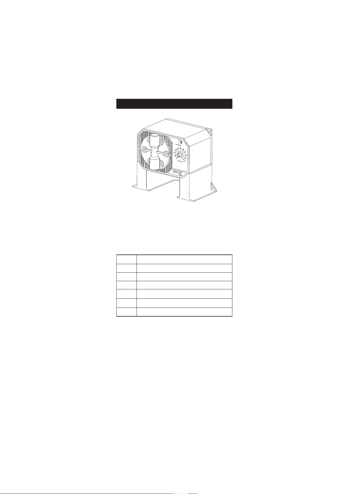
BlackStone pumps are equipped with a single control for pump
output.
Flow range is continuously adjustable from 0 to 100% of the
maximum capacity through a graded dial on the front of the pumps.
Seven models are available, each with a different dosing capacity:
BL 20 18.3 lph (4.8 gph) @ 0.5 bar (7.4 psi)
BL 15 15.2 lph (4.0 gph) @ 1 bar (14.5 psi)
BL 10 10.8 lph (2.9 gph) @ 3 bar (43.5 psi)
BL 7 7.6 lph (2.0 gph) @ 3 bar (43.5 psi)
BL 5 5.0 lph (1.3 gph) @ 7 bar (101.5 psi)
BL 3 2.9 lph (0.8 gph) @ 8 bar (116 psi)
BL 1.5 1.5 lph (0.4 gph) @13 bar (188.5 psi)
HIGH QUALITY MATERIALS
To provide the maximum protection for parts that are in contact
with aggressive chemicals, diaphragms, hose connectors and
pump heads are produced using materials as PVDF and PTFE.
The ball valves are constructed in glass. The body is made of fiberreinforced polypropylene for strength and durability.
5
Page 6

RELIABILITY THROUGH SIMPLICITY
All BlackStone pumps use the positive displacement solenoid
method of pumping. This method has fewer moving parts than a
standard motor-driven pump, and does not have the mechanical
failures associated with conventional pumps.
BlackStone's Positive Displacement design has several distinct
advantages over other types of mechanical designs:
• It is more accurate. Each stroke of the piston is precisely the
same as the stroke before it ... and the stroke after it.
• Positive displacement allows for easier self-priming.
• Pumping pressure is as high as 12 bar (176 psi). This allows
you to install your pump in the widest variety of tank-totank and tank-to-in-line applications.
• High accuracy and repeatability. A wire-wound potentiometer
and solid state electronics are combined to achieve greater
precision and control.
EASY INSTALLATION
Designed with mounting holes in the base as well as rear panel,
BlackStone pumps can be installed on a wall as well as directly on
top of tanks and drums.
There is no need for additional hardware.
All the controls and pump assemblies are conveniently located on
the front of the unit.
If the operator must access the pump head or control panel for any
reason, there is no need to dismount the unit.
6
Page 7

FLOW RATE CHART
The following charts show the relationship between their flow rate
and pressure.
An increase of pressure in the system decreases the flow rate.
BL1.5
bar (psi) lph (gph)
0.5 (7.4) 8.3 (2.20)
1 (14.7) 6.8 (1.80)
2 (29.4) 5.4 (1.43)
3 (44.1) 5.2 (1.38)
4 (58.8) 4.8 (1.27)
5 (73.5) 4.5 (1.19)
6 (88.2) 4.1 (1.08)
7 (102.9) 3.2 (0.85)
8 (117.6) 2.9 (0.77)
9 (132.3) 2.1 (0.56)
10 (147) 1.8 (0.48)
11 (161.7) 1.7 (0.45)
12 (176.4) 1.6 (0.42)
Pump output with 120 strokes/minut e
18,0
16,0
14,0
12,0
L
P
10,0
H
8,0
6,0
4,0
2,0
0,0
0,5123456789101112
9,0
8,0
7,0
6,0
L
P
5,0
H
4,0
3,0
2,0
1,0
0,0
0,512345 6789101112
BL3
BAR
BL1.5
Pump output with 120 strokes/minute
BAR
bar (psi) lph (gph)
0.5 (7.4) 15.8 (4.18)
1 (14.7) 12.2 (3.23)
2 (29.4) 9.3 (2.46)
3 (44.1) 7.9 (2.09)
4 (58.8) 6.5 (1.71)
5 (73.5) 5.0 (1.32)
6 (88.2) 4.0 (1.06)
7 (102.9) 3.3 (0.87)
8 (117.6) 2.9 (0.77)
9 (132.3) 2.5 (0.66)
10 (147) 2.2 (0.58)
11 (161.7) 1.9 (0.50)
12 (176.4) 1.5 (0.40)
BL3
BL5
bar (psi) lph (gph)
0.5 (7.4) 15.8 (4.18)
1 (14.7) 12.2 (3.23)
2 (29.4) 10.8 (2.86)
3 (44.1) 9.3 (2.46)
4 (58.8) 7.9 (2.09)
5 (73.5) 6.5 (1.72)
6 (88.2) 5.8 (1.53)
7 (102.9) 5.0 (1.32)
8 (117.6) 4.3 (1.14)
9 (132.3) 4.0 (1.06)
10 (147) 3.6 (0.95)
BL5
Pump output with 120 strokes/minut e
18,0
16,0
14,0
12,0
L
P
10,0
H
8,0
6,0
4,0
2,0
0,0
0,512345678910
BAR
7
Page 8

BL7
Pump output with 120 strokes/minu te
20,0
18,0
16,0
14,0
L
12,0
P
10,0
H
8,0
6,0
4,0
2,0
0,0
0,512345678
BAR
BL7
bar (psi) lph (gph)
0.5 (7.4) 17.2 (4.55)
1 (14.7) 13.6 (3.60)
2 (29.4) 10.8 (2.86)
3 (44.1) 7.6 (2.01)
4 (58.8) 6.0 (1.59)
5 (73.5) 5.7 (1.51)
6 (88.2) 5.4 (1.43)
7 (102.9) 4.4 (1.16)
8 (117.6) 3.6 (0.95)
BL10
bar (psi) lph (gph)
0.5 (7.4) 18.3 (4.84)
1 (14.7) 15.2 (4.02)
2 (29.4) 13.6 (3.60)
3 (44.1) 10.8 (2.86)
4 (58.8) 9.4 (2.49)
Pump output with 120 strokes/minu te
20,0
18,0
16,0
14,0
L
12,0
P
10,0
H
8,0
6,0
4,0
2,0
0,0
0,5 1 2 3
20,0
18,0
16,0
14,0
L
12,0
P
10,0
H
8,0
6,0
4,0
2,0
0,0
0,5 1 2 3 4
BL15
BAR
BL20
bar (psi) lph (gph)
0.5 (7.4) 18.3 (4.84)
1 (14.7) 15.2 (4.02)
2 (29.4) 13.6 (3.60)
20,0
18,0
16,0
14,0
L
12,0
P
10,0
H
8,0
6,0
4,0
2,0
0,0
0,5 1 2
BL10
Pump output with 120 strokes/minu te
BAR
bar (psi) lph (gph)
0.5 (7.4) 18.3 (4.84)
1 (14.7) 15.2 (4.02)
2 (29.4) 13.6 (3.60)
3 (44.1) 10.8 (2.86)
BL20
Pump output with 120 s trokes /minute
BAR
BL15
8
Page 9
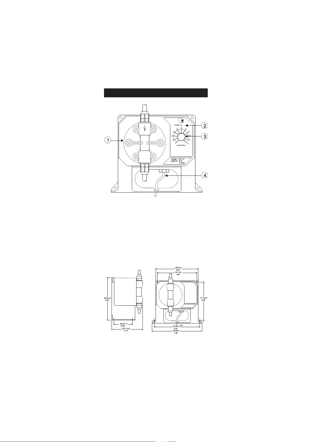
FUNCTIONAL DESCRIPTION
1. Pumphead
2. Stroke LED
3. Flow Rate % Knob
4. Power Cord
MECHANICAL DIMENSIONS
9
Page 10

SPECIFICATIONS
MAX FLOW RATE
BL1.5 1.5 lph (0.4 gph) @13 bar (188.5 psi)
BL3 2.9 lph (0.8 gph) @ 8 bar (116 psi)
BL 5 5.0 lph (1.3 gph) @ 7 bar (101.5 psi)
BL7 7.6 lph (2.0 gph) @ 3 bar (43.5 psi)
BL10 10.8 lph (2.9 gph) @ 3 bar (43.5 psi)
BL15 15.2 lph (4.0 gph) @ 1 bar (14.5 psi)
BL20 18.3 lph (4.8 gph) @ 0.5 bar (7.4 psi)
Adjustable from 0 to 100% of
maximum pump capacity
MATERIAL
PUMP CASING fiber-reinforced polypropylene
VALVES glass balls + O-rings in FPM/FKM
PUMPHEAD PVDF
DIAPHRAGM PTFE
TUBING polyethylene
SELF PRIMING Max. height: 1.5 m (5')
POWER SUPPLY
BL...-1 100/115 Vac; 50/60 Hz
BL...-2 220/240 Vac; 50/60 Hz
MAX POWER CONSUMPTION 200 W
PROTECTION IP65
ENVIRONMENT 0 to 50°C (32 to 122°F)
95% RH max
DIMENSIONS 194 x 165 x 121 mm (WxHxD)
(7.6 x 6.5 x 4.8")
WEIGHT 3 kg (6.6 lb.)
10
Page 11
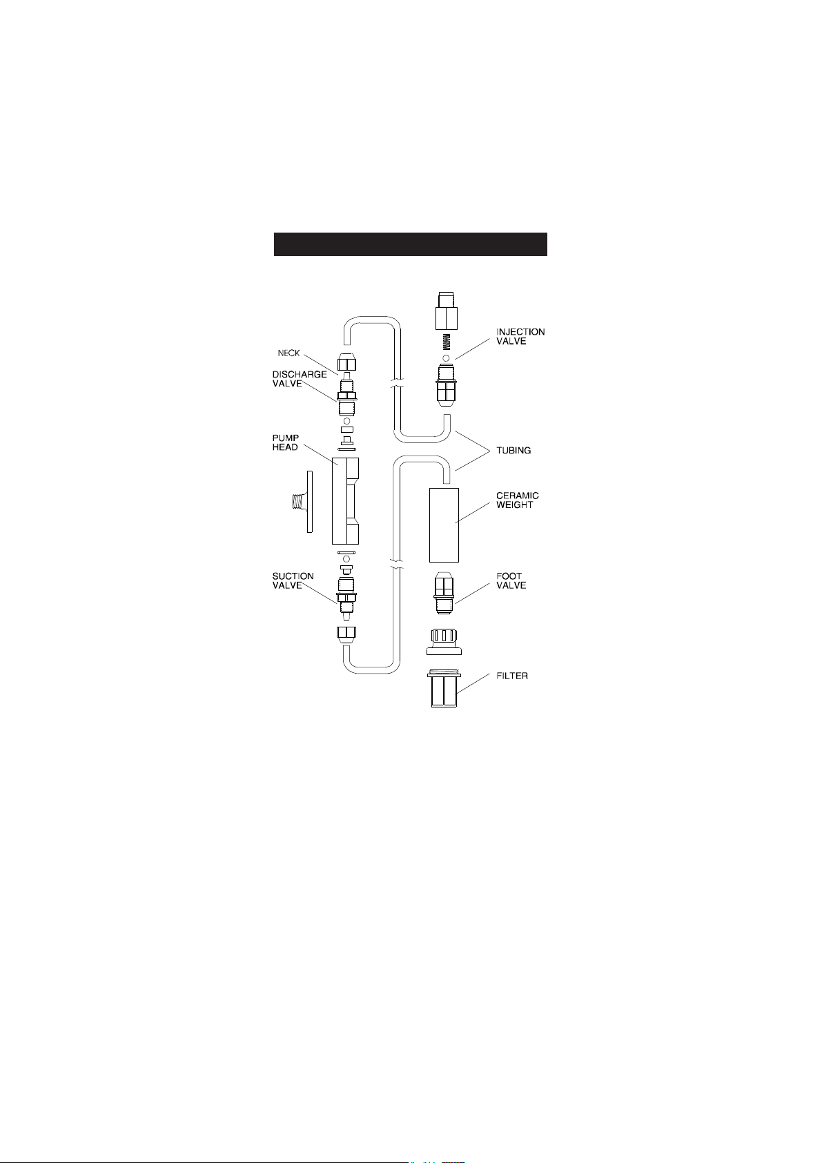
VALVE / HOSE ASSEMBLY DIAGRAM
11
Page 12
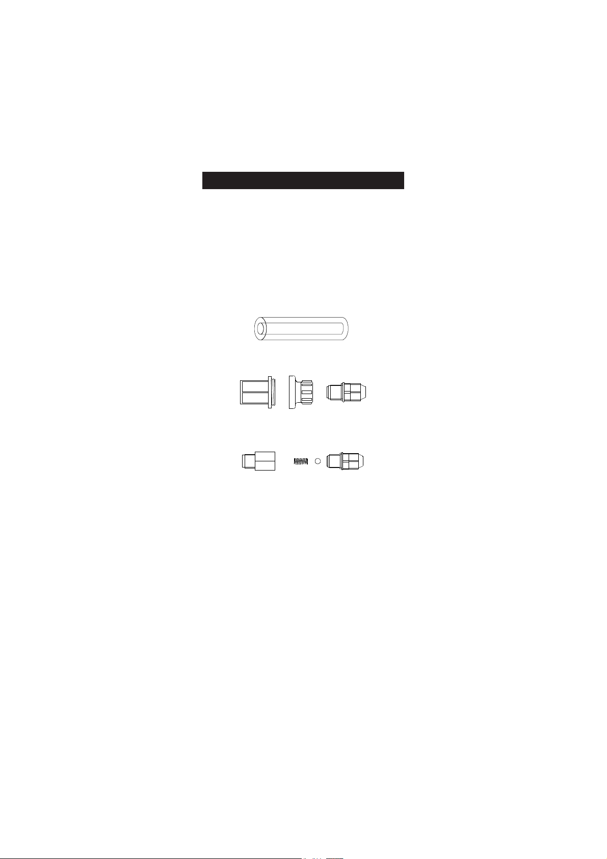
INSTALLATION
MATERIALS NEEDED
• LDPE hose (7 meter / 22 feet) (included) or other type of
tubing (PTFE, for example) more suitable for a specific
application (optional)
OPTIONAL ACCESSORIES
• 4 each, ceramic weights (HI 721008)
• 1 each, foot valve assembly (HI 721005)
• 1 each, injection valve assembly (HI 721004)
LOCATION
A suitable location should:
• be near to a power source
• be conveniently close to the injection point
• allow easy access to the flow rate control and pipe or hose
connections
• be no more than 1.5 meters (5 feet) above the operating
position of the suction valve assembly.
DIMENSIONS FOR INSTALLATION
BlackStone pumps are designed for permanent installation.
The pump can be mounted directly on a wall or tank.
12
Page 13

POWER REQUIREMENTS
BlackStone pumps are designed to operate to specifications within
the following voltage ranges:
100 - 130 Volts for -1 models
200 - 240 Volts for -2 models
To ensure maximum performance, check the voltage at the point
of supply to verify that it is sufficient. It is recommended that you
install a 1 Amp circuit breaker between the pump and the power
supply. This will give additional protection to the internal circuit
and provide a convenient way to disconnect the power supply prior
to servicing the pump, if needed.
INJECTION POINT
• Choose an injection point that allows you to mount the
injection valve assembly vertically.
• The spring in the injection valve assembly (HI 721004) adds
approximately 1.5 bar of back pressure. If pumping into a
high back pressure, the spring should be removed.
OTHER CONSIDERATIONS
• If you are mounting the system to a wall, column, etc., be sure
it is strong enough to support the weight of the entire system.
• The ambient temperature of the pump, when in operation,
should be between 0 and 50°C (32 to 122°F) and should be
protected from direct exposure to outdoor elements (direct
sunlight, rain, extreme temperatures, high humidity, etc.).
• Generally speaking, the shorter the suction distance, the more
efficient the pump operates.
• The pump should be placed in a conventional location that
will allow easy access to the control and connections. It should
be placed so that regular visual inspections of the connections
and hoses are facilitated.
13
Page 14
VERTICAL SURFACE MOUNTING
Once you have selected the best installation site, simply screw or
bolt the unit into a wall or mounting panel above the chemical
feed tank.
The 4 mounting screw holes on the pump will accommodate up to
a 5 mm (3/16") screw or bolt (remember to use heavy screws or
bolts to secure the system).
Be sure you do not over tighten and cause excessive stress on the
mounting holes.
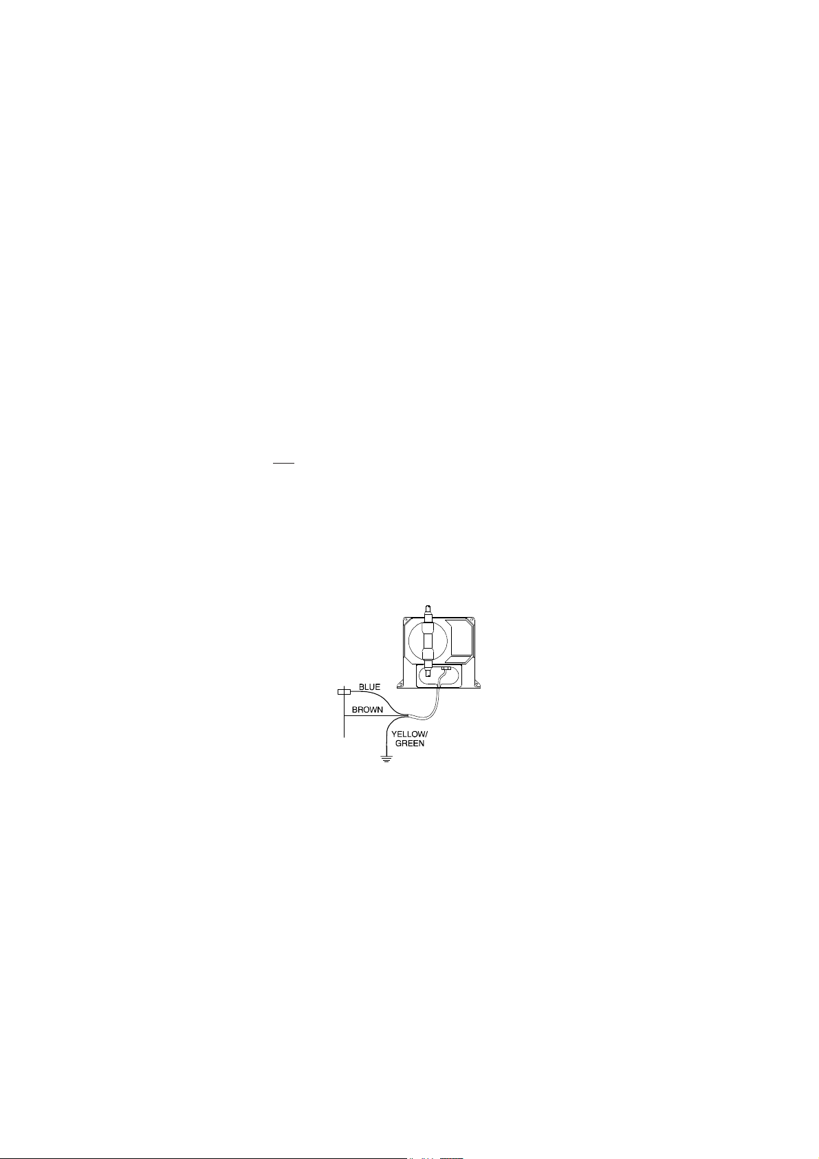
ELECTRICAL CONNECTIONS
Note: All cables must be according to local electrical codes.
For safety of the users, the pump has to be grounded.
The pump should be connected to a single phase power source.
Color coding for wires:
Blue - Live
Brown - Neutral
Yellow/Green - Ground (earth)
It is recommended that the system be connected to a power line/
leg equipped with a circuit breaker of 1 Amp.
14
Page 15
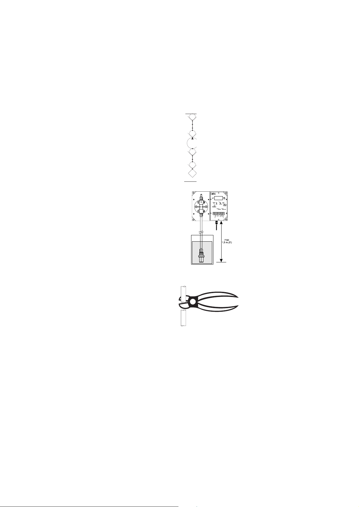
PERMANENT CONNECTION USING 3/8"PVC PIPE
-
All piping for the pump feed and
discharge should be plumbed to
the location of the pump.
The threads on both valve assemblies
allow the use of standard 3/8"
(European) pipe fittings for
permanent pipe connections.
The foot valve assembly
UNION CONNECTION
ADAPTER
DISCHARGE VALVE
PUMP
SUCTION VALVE
ADAPTER
FOOT VALVE
FILTER
(HI 721005) should always hang
vertically and not lay horizontal
Diagram for Rigid Pipe Hose
on the bottom of the tank or
drum.
A vertical assembly will ensure
that the valve is positioned properly
and prevent loss of prime.
For the U.S. standard installations,
use PVC adapters to connect the
suction and discharge valves to
the PVC pipe.
HOSE CONNECTIONS
• Cut a long enough section
of the hose to reach the
suction valve of the
pumphead from the feed
tank. Allow some slack in
the hose and be sure it is
not kinked or twisted.
15
Page 16
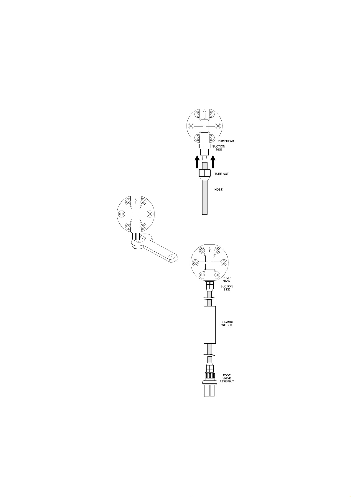
• Slip a hose connector onto
the hose over the head
valve and up to the bottom
of the threads ensuring it
is fully seated.
• Slide the connector up to
the threads and tighten to
form a seal.
• Slip the ceramic weight
(HI 721008) and a
connector over the other
end of the hose.
• Attach the foot valve
assembly (HI 721005) to
the hose and slide the
connector up to the
threads and tighten to
form a seal.
16
Page 17
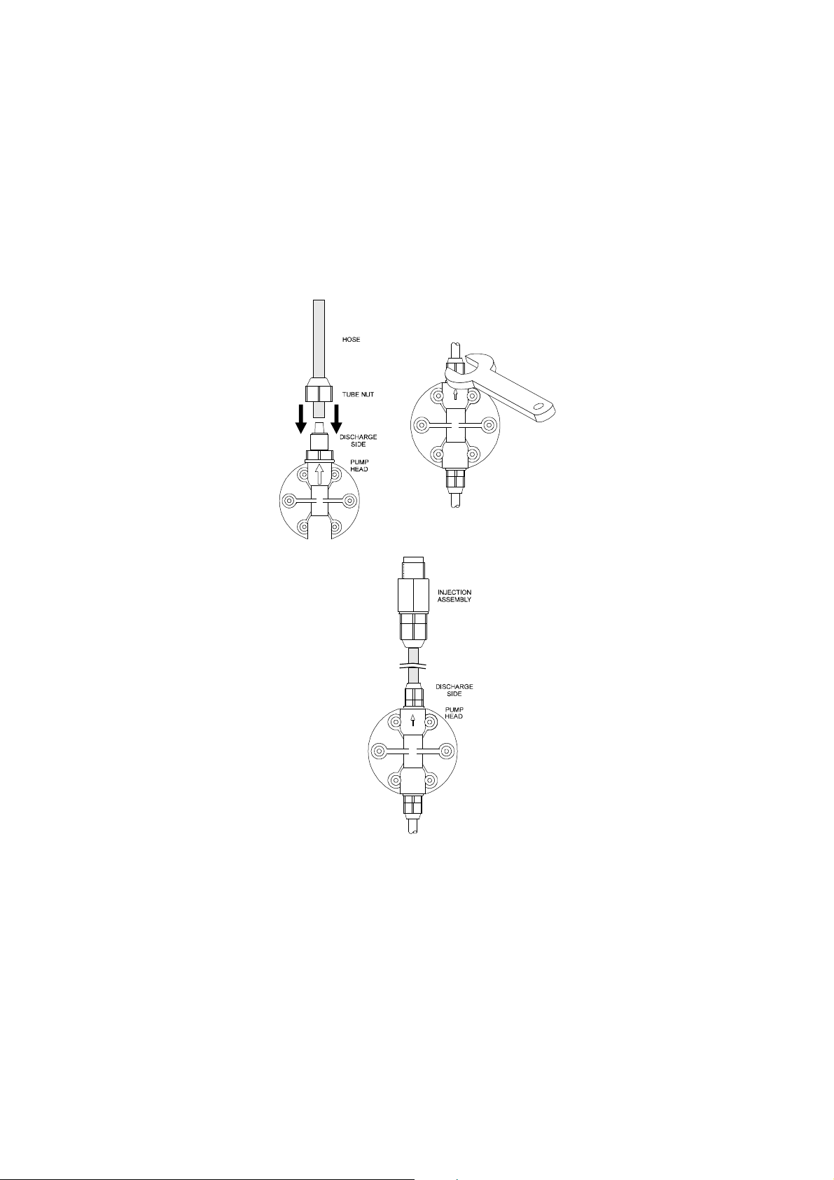
• Repeat the same installation procedure for the hose
connections on the discharge end with the injection
assembly (HI 721004).
• Secure the hose so that its movement is minimized when the
pump is operating. Excessive hose movement could cause the
connectors to loosen and result in leakage.
17
Page 18
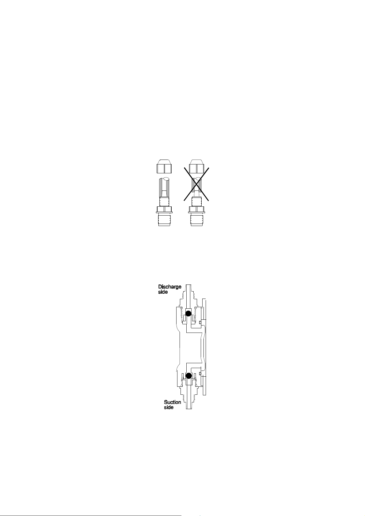
ASSEMBLING THE HOSE TO THE VALVE
The end of the valve is specially tapered to form a leak free seal
when the hose is properly installed.
Be sure to seat the hose completely so that there is no gap. Push
the hose until it covers the end of the valve completely.
SUCTION AND DISCHARGE VALVES
The suction and discharge valves located on the pumphead
should not be interchanged as they are different internally. The
discharge valve is fitted with a valve guide and will not function
properly if used on the suction side.
18
Page 19
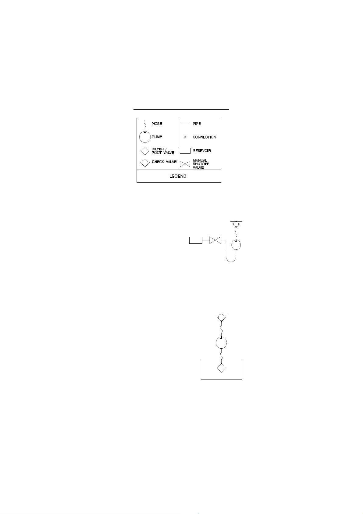
EXAMPLE OF TYPICAL INSTALLATIONS
FLOODED SUCTION INSTALLATION
Suggested Installation for consistent
output when using a low stroke rate.
Also suggested for highly viscous
chemicals.
A slight suction pressure avoids
self-priming problems, especially
with high viscosity liquids.
SUCTION LIFT INSTALLATION
Suggested installation for most
in-line applications with nominal
output and pressures.
The maximum self-priming height
is 1.5 m (5 ft.). It is advisable to
install a level controller in order to
stop the pump when feed tank
liquid level is low.
19
Page 20
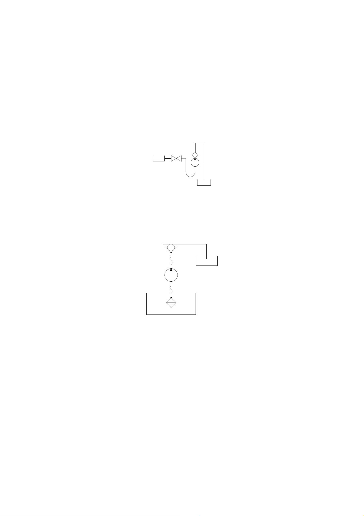
UPHILL INSTALLATION
Suggested installation whenever the supply is located higher than
the discharge point; typically a waste water application.
It is important to install the Injection valve to prevent siphoning.
DOWNHILL INSTALLATION
Suggested installation when pumping from one container to
another, each at different levels and with only nominal pressure.
20
Page 21
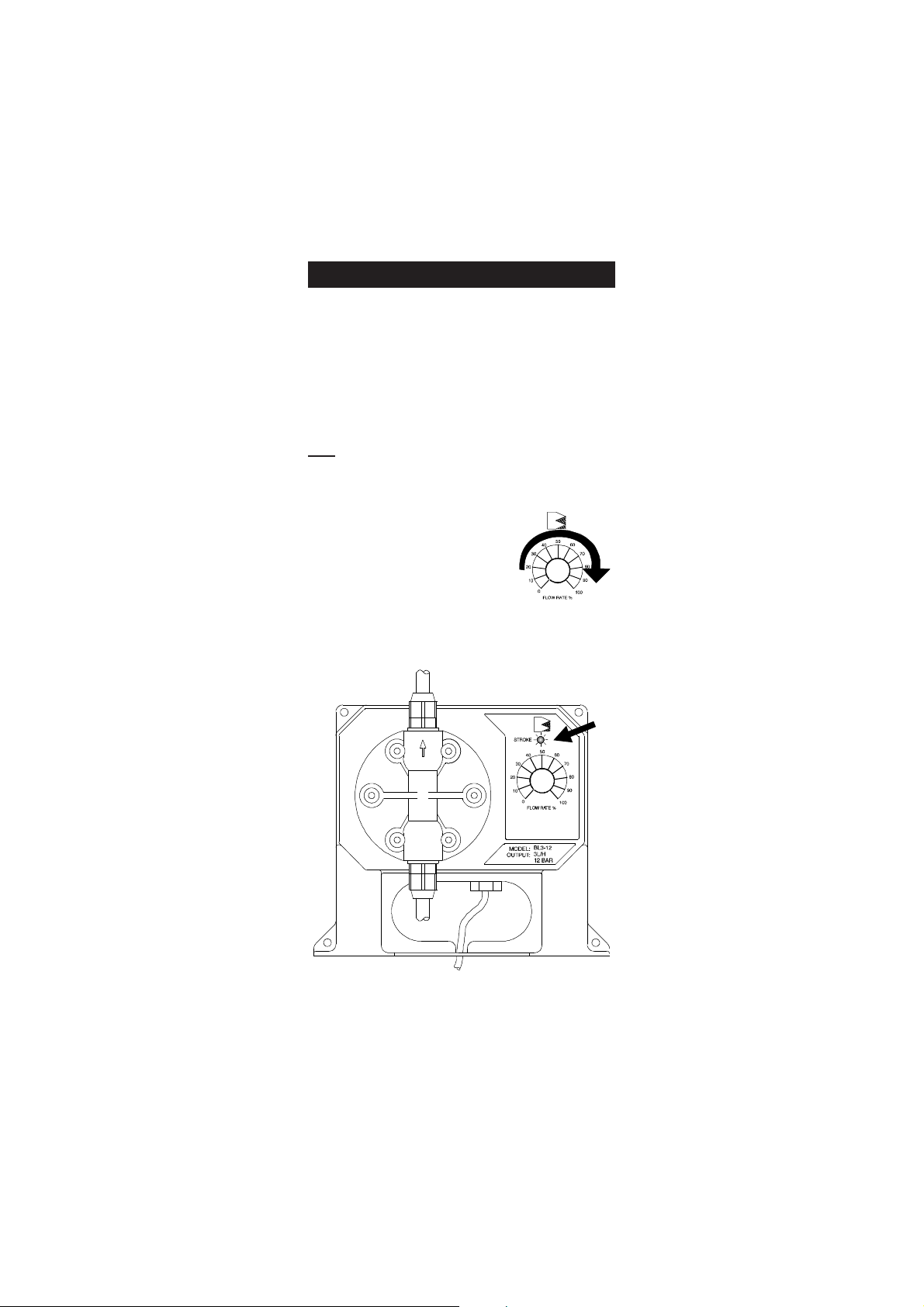
OPERATIONAL GUIDE
START-UP
At start-up, purge all chemical gases and air from the suction
tubing, valves and pump head. Start the pump.
When all the air or gas is vented, the solution being metered will
appear in the output line.
Note:Only when operating under pressure, the pump must
be started unloaded.
An external Flow Rate Control
(potentiometer) on the face of the
pump allows to adjust the flow
up to 100% of the pump's rated
capacity.
A LED indicator will light up each
time a stroke begins.
21
Page 22
OPERATING PRESSURE AND BACK PRESSURE
Operating pressure is a combination of back pressure plus all of
the other resistances to flow present in your system.
BlackStone Pumps are designed to dose their rated output at the
operating (
Therefore,
rated
) pressure.
rated
pressure of the pump you install should be close
to operating pressure present in the system.
Too little back pressure can cause the pump to overdose.
To prevent this from happening on a low back pressure installation,
a spring has been added to the discharge/anti-siphon valve
assembly (HI 721004).
When pumping into a high back pressure, the spring should be
removed.
ACTUAL FLOW RATE
The actual flow rate depends upon the operating pressure which
includes resistance at the injection fittings, hose and piping, the
chemical viscosity and suction lift. The Flow Rate Control adjusts
rated
the flow up to 100% of the
output. Less back pressure will
increase the output, more will decrease it. To determine the correct
setting for your application, use the following procedure.
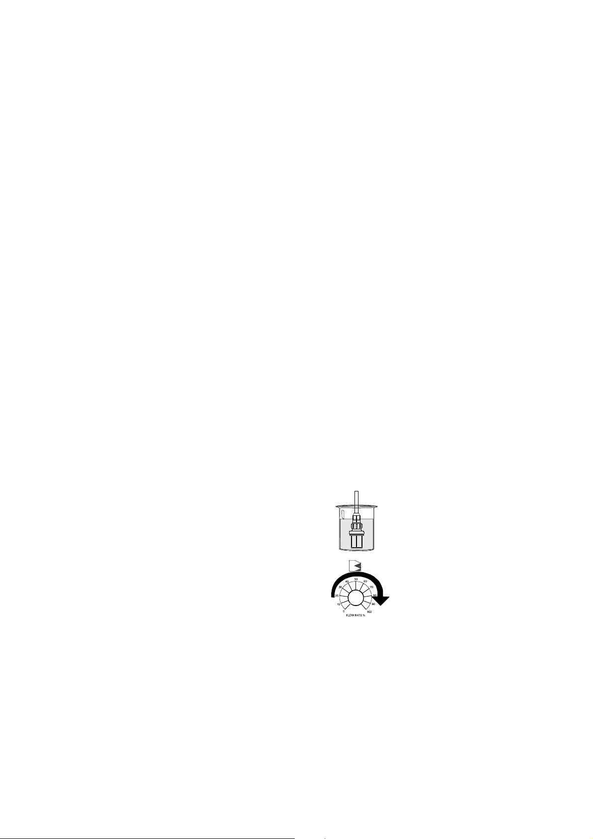
1. Be sure that the pump is primed and that the output connections
are completed at the injection point.
2. Place the foot valve assembly
(HI 721005) in a graduated
container with 500 mL of the
solution to be dosed.
3. Switch the pump from OFF to the
100% setting and run until the
system has been fully reprimed.
Switch OFF and refill the
container to the 500 mL level.
22
Page 23

4. Switch the pump ON to the estimated
setting and run for a specific amount
of time (e.g. 1 minute). Count the
number of strokes, length of time, and
volume pumped.
Note: It is suggested that you run the test for as long as possible
to maximize the accuracy.
For example, if at the maximum setting of 100% you find you
pumped 200 mL in one minute, your hourly output would be
12 liters/hour (200 mL x 60 min. = 12000 mL/hr). If your
application called for 9 liters/hour, turn the Flow Rate Control
to 7 (9/12). Run the test again to verify the results.
TROUBLESHOOTING GUIDE
ELECTRICAL
The pump does not operate when turned ON:
• Check the power supply and connections. Voltage should be
between 100 - 130 Vac for -1 models and between 200 240 Vac for -2 models.
• Check wiring color scheme. See Installation section or call for
technical assistance.
LIQUID
The pump operates but does not prime:
• Check for a clogged or loose filter on the suction valve
assembly. Retighten if necessary.
• Check to see if the pump is too high above the foot valve
assembly (HI 721005) in the feed tank. This vertical
distance should not exceed 1.5 meters (5 feet). Either
lower the pump or raise the feed tank.
• Check the pumphead, suction and discharge valves for
blockage.
23
Page 24

Pump flow rate is reduced:
• Check the pumphead, discharge and injection valve assembly
for any clogging. Clean and reassemble.
• Check for any additional back pressure created since the last
flow rate was conducted.
• Check for any changes in the viscosity of the chemicals being
used. Increase the % flow by adjusting the Flow Rate control
to a higher setting and run a Flow Rate test.
• Be sure that valves have been properly installed in the
pumphead.
Leakage at the connections:
• Be sure that the hose is fully seated and hose connectors are
tight.
• Be sure that valves are tight and O-rings are in place.
Leakage around the pumphead:
• Be sure that the valves are tight and O-rings are in place and
the head screws (hex bolts) are tight.
24
Page 25

MAINTENANCE
Your BlackStone Pump is designed to give you years of trouble-free
service. Maintenance should be the preventative type, that is,
periodic cleaning and inspecting for any damage or leakage.
CLEANING THE SUCTION, DISCHARGE AND INJECTION
VALVES
Remove the valves from the pumphead, the injection fitting and
the feed.
Keep the suction and discharge valves separated as they are
interchangeable.
Disassemble each valve and clean it with a neutral liquid. Inspect
the PVDF springs.
After cleaning the glass balls, inspect them for any excessive wear
due to abrasion from the chemical. Replace if necessary with parts
from HI 721102, HI 721103, HI 721104 and HI 721105.
When reinstalling the valves into the pumphead, tighten by hand
first and then with a wrench ¼ to ½ turn.
INSPECTING THE HOSE (if used as supplied with the pump)
Inspect to see if the hose has worn out or weakened due to the
chemicals. Pay particular attention for any signs of abrasion or
discoloration. Also check the connectors to ensure they are tight.
Replace if necessary with parts from HI 720032.
not
25
Page 26

CLEANING THE PUMPHEAD
The pumphead should be cleaned at regular intervals and at least
once a year. Remove the deposits that form in the cavities with a
solution that is neutral to the chemical the pump has been dosing.
Inspect the head for any cracks or worn areas.
Replace if necessary with parts from the pumphead spare part
HI 721106 (for BL7, BL10, BL15 and BL20) or HI 721107 (for
BL1.5, BL3 and BL5).
SCHEDULED MAINTENANCE
After 50 hours
Tight the pumphead screws with a torque force of 2.5 Nm (22" lbf).
After 12 months
It is recommended to replace HI 721102, HI 721103 (suction
and discharge valves assemblies) as well as the O-rings. The LDPE
hose can also deteriorate over time and, for safety reasons, should
also be changed with HI 720032.
After 24 months
It is recommended to replace HI 721102, HI 721103, HI 720032
and HI 721106 (for BL7, BL10, BL15 and BL20) or HI 721107
(for BL1.5, BL3 and BL5).
26
Page 27

CHEMICAL COMPATIBILITY GUIDE
Partial Listing of Chemicals that can be used with BlackStone
Pumps
(Rated for 45°C. For higher temperatures consult your dealer or
nearest Hanna Service Center.)
Adipic Acid
Alcohol Amyl
Alcohol, Diacetone
Alcohol, Isopropyl
Alcohol, Methyl
Aluminium, Ammonium Sulfate
Aluminium Chloride
Aluminium Sulfate
Alums
Ammonium Carbonate
Ammonium Chloride
Ammonium Fluoride
Ammonium Hydroxide
Ammonium Nitrate
Ammonium Phosphate
Ammonium Sulfate
Aqua Ammonia
Arsenic Acid
Barium Carbonate
Barium Chloride
Barium Hydroxide
Barium Sulfate
Beer
Beet Sugar Liquors
Bismuth Carbonate
Back Liquor
Bleach
Borax
Boric Acid
Bromic Acid
Butyric Acid
Calcium Bisulfite
Calcium Carbonate
Calcium Chlorate
Calcium Chloride
Calcium Hydroxide
Calcium
Hypochlorite
Calcium Nitrate
Calcium Sulfate
Carbonic Acid
Castor Oil
Caustic Soda
Chloral Hydrate
Chromic Acid 50%
Citric Acid
Copper Chloride
Copper Cyanide
Copper Nitrate
Copper Sulfate
Corn Oil
Cottonseed Oil
Cresylic Acid
Crude Oil
Dextrose
Detergents (general)
Diesel Fuel
Dictyl Phthalate
Disodium Phosphate
Ethanol (1-95%)
Ethylene Dichloride
Ethylene Glycol
Fatty Acids
Ferric Chloride
Ferric Nitrate
Ferric Sulfate
Ferrous Chloride
Ferrous Sulfate
Fluoboric Acid
Fluosilicic Acid
Formaldehyde
Fruit Juice Pulp
Fuel Oil
Gallic Acid
Gasoline, Refined
Glucose
Glycerine or Glycerol
Glycolic Acid 30%
Hexane
Hydrazine
Hydrobromic Acid 20%
Hydrochloric Acid (Concentrated)
Hydrochloric Acid (Diluted)
Hydrogen Sulfide Aqueous Solution
27
Page 28

Hypochlorous Acid
Kerosene
Lactic Acid
Lard Oil
Lauric Acid
Lead Acetate
Linoleic Acid
Linseed Oil
Lithium Salts
Magnesium Carbonate
Magnesium Chloride
Magnesium Hydroxide
Magnesium Nitrate
Magnesium Oxide
Magnesium Sulfate
Maleic Acid
Malic Acid
Mercuric Chloride
Methanol
Methyl Sulfate
Milk
Mineral Oils
Naptha Petroleum
Nickel Chloride
Nickel Sulfate
Nitric Acid 50%
Oils and Fats
Oleic Acid
Olive Oil
Oxalic Acid
Palmitric Acid
Perchloric Acid 70%
Perchloroethylene
Petroleum Oils (sour)
Phenol
Phosphoric Acid
Photographic Solutions
Plating Solutions
Potassium Carbonate
Potassium Bromide
Potassium Chlorate
Potassium Chloride
Potassium Cyanide
Potassium Ferrocyanide
Potassium Hydroxide
Potassium Nitrate
Potassium Permanganate 10%
Potassium Phosphate
Potassium Sulfate
Propyl Alcohol
Propylene Dichloride
Sea Water
Silver Nitrate
Silver Plating Solutions
Soaps
Sodium Acetate
Sodium Bicarbonate
Sodium Bisulfate
Sodium Bisulfite
Sodium Borate
Sodium Chlorate
Sodium Chloride
Sodium Cyanide
Sodium Fluoride
Sodium
Hexametaphosphate
Sodium Hydroxide 50%
Sodium Hypochlorite 18%
Sodium Metaphosphate
Sodium Nitrate
Sodium Peroxide
Sodium Phosphate
Sodium Silicate
Sodium Sulfate
Sodium Sulfide
Sodium Sulfite
Sodium Thiosulfate
Sour Crude Oil
Stannic Chloride
Stannous Chloride
Stearic Acid
Sulfur
Sulfuric Acid Concentration
Sulfurous Acid
Tannic Acid
Tanning Liquors
Tartaric Acid
Tetrachlorethane
Tetraethyl Lead
Tetralin
Tin Salts
Vegetable Oils
Vinegar
Water Acid, Mine
Water, Fresh
Water, Distilled
Water, Salt
Whiskey
Wines
Zinc Chloride
Zinc Sulfate
28
Page 29
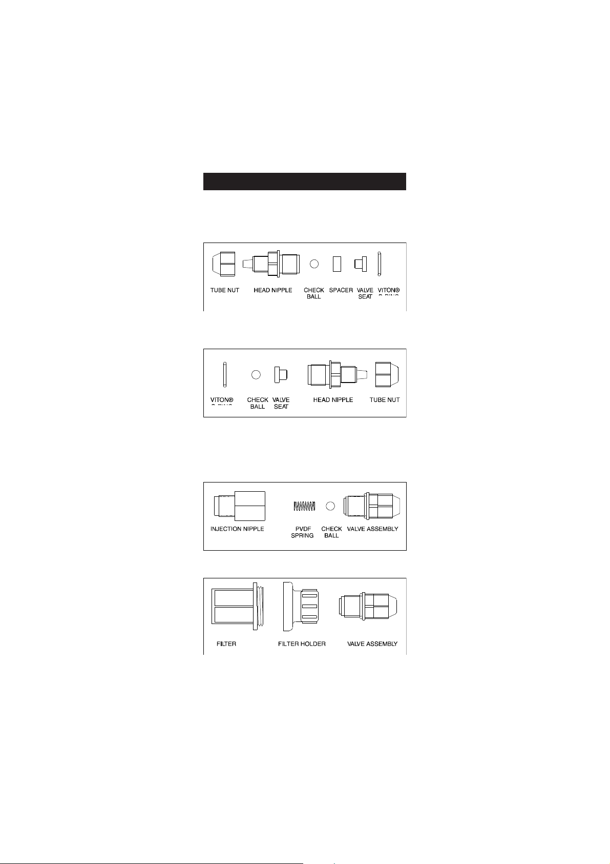
ACCESSORIES
SPARE PARTS
HI 721102 Discharge Valve
(Glass Ball, Valve O-Ring, Hose Connector)
HI 721103 Suction Valve (Glass Ball, Valve O-Ring, Hose
Connector)
HI 721003 10 x Glass Balls
10 x Valve O-Rings
HI 721004 Injection Valve Assembly
HI 721005 Foot Valve Assembly
HI 721006 PVDF Springs, 4 pcs
HI 720032 LDPE Hose - 100 m (330')
29
Page 30
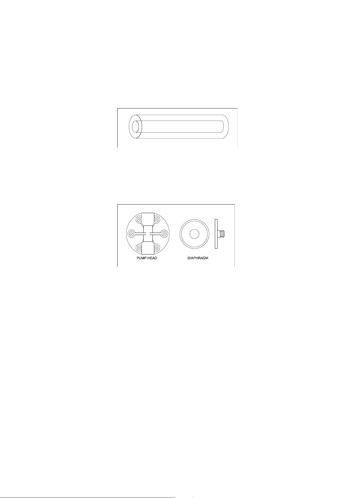
HI 721008 Ceramic Weights, 4 pcs
HI 721101 Pumphead, O-Ring, 6 screws and washers
HI 721106 (for BL7, BL10, BL15 and BL20)
Pumphead
Large PTFE Diaphragm
Aluminum Piston
Aluminum Disk
HI 721107 (for BL1.5, BL3 and BL5)
Pump-head
Small PTFE Diaphragm
Aluminum Piston
OTHER ACCESSORIES
HI 731326 Calibration screwdriver (20 pcs)
30
Page 31
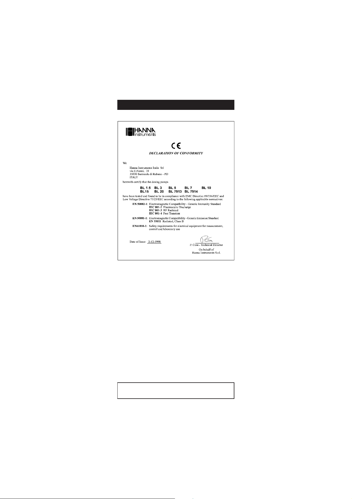
CE DECLARATION OF CONFORMITY
RECOMMENDATIONS FOR USERS
Before using these products, make sure that they are entirely suitable for
the environment in which they are used.
Operation of these instruments in residential area could cause unacceptable
interferences to radio and TV equipments, requiring the operator to take
all necessary steps to correct interferences.
Any variation introduced by the user to the supplied equipment may
degrade the instruments' EMC performance.
Hanna Instruments reserves the right to modify the design,
construction and appearance of its products without advance notice.
31
Page 32

Hanna Instruments Inc.
Highland Industrial Park
584 Park East Drive
Woonsocket, RI 02895 USA
Technical Support for Customers
Tel. (800) 426 6287
Fax (401) 765 7575
E-mail [email protected]
www.hannainst.com
Local Sales and Customer Service Office
Printed in EUROPE
(ROMANIA) MANBL 02/10
32
 Loading...